A kind of high-building construction hydraulic climbing scaffold
Technical field
The utility model relates to a kind of construction implement, and particularly a kind of hydraulic pressure that utilizes is the highrise building lifting means of driving force.
Background technology
Along with the develop rapidly of Building Trade in China, highrise building and super highrise building are more and more, and lifting means is highrise building and super highrise building external wall construction auxiliary equipment commonly used, and its selection also is a major issue in the Design of Construction Organization.At present external wall construction lifting means commonly used is outside the building to enclose with steel pipe to build, until bind with building, this structure needs a large amount of material and artificial, in highrise building, the drawback that seems is large especially, do not possess elevating function such as self, poor safety performance, and build, remove very difficult.
In recent years, for overcoming the shortcoming of traditional scaffold, some new improvement have appearred.For example application number is that 200720035043.9 Chinese patent discloses a kind of " skyscraper platform ", and this climbing frame comprises hitch frame, runner frame, wall fixed bracket and lifting false work 4 parts; This climbing frame is equipped with some laterally "T"-shaped wall fixed bracket, the wall fixed bracket front end on wall, be fixedly connected with vertical runner frame, the chute of runner frame and slideway rail are slidingly installed, a side of slideway rail, and the lifting false work with the rectangle frame is fixedly connected with respectively; Hitch frame is fixed on the top that is higher than wall fixed bracket, and it is fixedly connected with lifting false work by the steel wire traction rope, by the traction of pull rope, impels lifting false work to move up and down, thereby carrying people and thing carry out constructions work.The shortcoming of top of building although this climbing frame has overcome that traditional scaffold begins to build from ground has been saved some materials and artificial, is steel wire as the mechanism of traction lifting, and existence and stability is not good and be difficult to the problem of balance.
Summary of the invention
For overcoming time-consuming, the uneasy congruent problem of existing scaffold expense material, the utility model provides a kind of constantly climbs lifting means take hydraulic pressure as driving force repeatedly, and lifting hydraulic lifting device freely, and this device materials consumption is few, use cost is low, good stability.
High-building construction hydraulic climbing scaffold described in the utility model comprises bracing frame and lifting means, and the bracing frame height is that 4~4.5 times individual layer building is high;
Described lifting means is by hydraulic pump 4, hydraulic cylinder 5, moving slider 6, cassette guide rail 7, fixedly slide block 8, piston rod 9, hydraulic pressure strut 10, lock pin 11 consists of, the parallel cassette guide rail 7 with two in the bottom of bracing frame is fixedly connected with, be provided with the fixedly slide block 8 that is equally spaced two closed slide 7 bottoms, fixedly slide block 8 mid portions are provided with two grooves that coincide with guide rail 7 cross sections, two closed slides 7 respectively in the embedded groove with fixing slide block 8 vertical being fixedly connected with, simultaneously, fixedly the two side portions of slide block 8 respectively is provided with 1-5 bolt hole, lifting means is fastenedly connected with through-wall bolt and body of wall by this bolt hole, per two fixedly the distance between the slide block 8 greater than the effective travel of hydraulic cylinder;
Epimere between two guide rails 7 is equipped with hydraulic cylinder 5, and the ear arm on the upper end of hydraulic cylinder 5 and guide rail 7 tops is by lock pin 11 releasable connections, and the lower end is fixedly connected with guide rail 7; The upper end of piston rod 9 is placed in the hydraulic cylinder 5; The other end of piston rod 9 and hydraulic pressure strut 10 are by lock pin 11 releasable connections, equidistantly be fixedly connected with 3~6 moving sliders 6 on the hydraulic pressure strut 10, there is the chute that matches with guide rail 7 shape of cross sections in the cross section of moving slider 6, moving slider 6 vertically is installed on the guide rail 7 by the chute that arranges on it, and the chute on the moving slider 6 can move up and down along guide rail 7.
Connector lock pin between piston rod 9 and the hydraulic pressure strut 10 is the crossed joint connecting rod.
Described moving slider 6 or fixedly the both sides of slide block 8 1-3 bolt hole arranged respectively.
Described cassette guide rail 7 is stung a kind of in tooth card, round steel anchor ear card, bolt card, shaped steel, square steel clamping plate card, roller clip integrated circuit board, channel-section steel subtend cover card, the boots shell type for indent.
Recessed sting tooth card, round steel anchor ear card, bolt card, shaped steel, square steel clamping plate card, roller clip integrated circuit board, channel-section steel subtend cover card, the boots shell type of chute on the moving slider 6 for cooperating with guide rail 7.
Be to improve the repeat usage of boring, reduce and install and use labour intensity, the distance between can any two moving sliders 6 be set to any two fixedly the distance between the slide block 8 equate, can guarantee that the two can repeat also replaceable use and hole.
Described high-building construction is divided into initial stationary state and climb mode in use with hydraulic climbing scaffold, when initial stationary state, fixedly slide block 8 is fixed on elevating mechanism on the body of wall with through-wall bolt by the bolt hole of both sides, locks simultaneously the bolt on the moving slider 6; Enter climb mode when needing to rise, at first unclamp bolt on the moving slider 6, the primer fluid press pump, oil enters hydraulic cylinder 5 by oil pipe, under the effect of oil pressure, piston rod 9 is drawn high, moving up enters in the hydraulic cylinder 5, and band hydrodynamic pressure strut 10 makes moving slider 6 move up along guide rail 7, moves on the moving slider 6 in the effective travel of hydraulic cylinder 5, fixedly moving slider 6, fixedly slide block 8 unclamps again, under the effect of oil pressure, moves on the hydraulic cylinder 5, drive guide rail 7 and fixedly slide block 8 rise overally, the whole climbing frame corresponding distance that just moves up can repeat above-mentioned action, until rise to desired height, then fixing fixedly slide block 8 can use at metope.
The difference of rising and descending is to operate by opposite method to get final product, and carries out repeatedly the motion of repetition by above process, can realize lifting.
The utlity model has following beneficial effect:1. because hydraulic climbing scaffold directly is fastenedly connected with the body of wall of building, so fundamentally avoided the danger caving in, topple over, be welded with bracing frame on the guide rail, bracing frame has the function of support, steady job platform.
2. hydraulic climbing scaffold volume described in the utility model is little, simple in structure, and installation saves time, the saving of labor, material-saving, easy disassembly.
3. hydraulic climbing scaffold described in the utility model is take hydraulic pressure as promoting power, and reliability is high, safety and stability, and hoisting velocity is fast.
4. lift rail and working platform fulcrum each other promotes mutually, need not artificial turnover, saves artificial.
5. the utility model hydraulic climbing scaffold can be with the multiaspect wall form to climb together simultaneously, only needs tower crane to carry out once lifting and the dismounting of template in the total work progress, has greatly saved tower crane and has hung inferior.
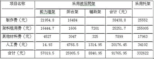
6. the product economy Efficiency Comparison is analyzed
With high-rise 25 layers of residence floor engineering, adopt the utility model hydraulic climbing scaffold since the 8th layer, can greatly save cost.
Description of drawings
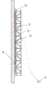
Fig. 1 is the utility model hydraulic climbing scaffold structural representation.
Fig. 2 is Figure 1B-B sectional view.
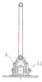
Fig. 3 is that the utility model hydraulic climbing scaffold and metope installation concern schematic diagram.
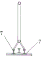
Fig. 4 is Figure 1A-A sectional view.
Fig. 5 is Fig. 1 top view.
Among the figure, hydraulic pump-4, hydraulic cylinder-5, moving slider-6, guide rail-7, fixedly slide block-8, piston rod-9, hydraulic pressure strut-10, lock pin-11.
The specific embodiment
Below in conjunction with accompanying drawing the utility model is described further, but be not limited to embodiment.
Embodiment 1
A kind of high-building construction hydraulic climbing scaffold comprises bracing frame and lifting means, and the bracing frame height is that 4 times individual layer building is high;
Lifting means is by hydraulic pump 4, hydraulic cylinder 5, moving slider 6, cassette guide rail 7 is stung tooth for indent, fixedly slide block 8, piston rod 9, hydraulic pressure strut 10, lock pin 11 consists of, the parallel cassette guide rail 7 with two in the bottom of bracing frame is fixedly connected with, be provided with the fixedly slide block 8 that is equally spaced two closed slide 7 bottoms, and per two fixing 2 meters effective travels greater than hydraulic cylinder of the distance between the slide block 8, fixedly slide block 8 mid portions are provided with two grooves that coincide with guide rail 7 cross sections, two closed slides 7 respectively in the embedded groove with fixing slide block 8 vertical being fixedly connected with, simultaneously, fixedly the two side portions of slide block 8 respectively is provided with 2 bolts hole, and lifting means is fastenedly connected with through-wall bolt and body of wall by this bolt hole;
Epimere between two guide rails 7 is equipped with hydraulic cylinder 5, and the ear arm on the upper end of hydraulic cylinder 5 and guide rail 7 tops is by lock pin 11 releasable connections, and the lower end is fixedly connected with guide rail 7; The upper end of piston rod 9 is placed in the hydraulic cylinder 5; The other end of piston rod 9 and hydraulic pressure strut 10 are by lock pin 11 releasable connections, equidistantly be fixedly connected with 3 moving sliders 6 on the hydraulic pressure strut 10, there is the chute that matches with guide rail 7 shape of cross sections in the cross section of moving slider 6, moving slider 6 vertically is installed on the guide rail 7 by the chute that arranges on it, and the chute on the moving slider 6 can move up and down along guide rail 7.
Embodiment 2
The high-building construction hydraulic climbing scaffold comprises bracing frame and lifting means, and the bracing frame height is that 4.5 times individual layer building is high;
Lifting means is by hydraulic pump 4, hydraulic cylinder 5, moving slider 6, card guide rail 7 is the roller clip integrated circuit board, fixedly slide block 8, piston rod 9, hydraulic pressure strut 10, lock pin 11 consists of, the parallel cassette guide rail 7 with two in the bottom of bracing frame is fixedly connected with, be provided with the fixedly slide block 8 that is equally spaced two closed slide 7 bottoms, and per two fixedly the distance between the slide block 8 greater than the effective travel of hydraulic cylinder, fixedly slide block 8 mid portions are provided with two grooves that coincide with guide rail 7 cross sections, two closed slides 7 respectively in the embedded groove with fixing slide block 8 vertical being fixedly connected with, fixedly the two side portions of slide block 8 respectively is provided with 5 bolts hole, and lifting means is fastenedly connected with through-wall bolt and body of wall by this bolt hole;
Epimere between two roller clip card guide rails 7 is equipped with hydraulic cylinder 5, and the ear arm on the upper end of hydraulic cylinder 5 and guide rail 7 tops is by lock pin 11 releasable connections, and the lower end is fixedly connected with guide rail 7; The upper end of piston rod 9 is placed in the hydraulic cylinder 5; The other end of piston rod 9 and hydraulic pressure strut 10 are by 11 releasable connections of crossed joint connecting rod lock pin, equidistantly be fixedly connected with 6 moving sliders 6 on the hydraulic pressure strut 10, there is the chute that matches with guide rail 7 shape of cross sections in the cross section of moving slider 6, moving slider 6 vertically is installed on the guide rail 7 by the chute that arranges on it, and the chute on the moving slider 6 can move up and down along guide rail 7.
Embodiment 3
The high-building construction hydraulic climbing scaffold comprises bracing frame and lifting means, and the bracing frame height is that 4 times individual layer building is high;
Lifting means is by hydraulic pump 4, hydraulic cylinder 5, moving slider 6, guide rail 7 is the boots shell type, fixedly slide block 8, piston rod 9, hydraulic pressure strut 10, lock pin 11 consists of, the parallel boots shell type guide rail 7 with two in the bottom of bracing frame is fixedly connected with, be provided with the fixedly slide block 8 that is equally spaced two closed slide 7 bottoms, and per two fixedly the distance between the slide block 8 greater than the effective travel of hydraulic cylinder, fixedly slide block 8 mid portions are provided with two grooves that coincide with guide rail 7 cross sections, two closed slides 7 respectively in the embedded groove with fixing slide block 8 vertical being fixedly connected with, fixedly the two side portions of slide block 8 respectively is provided with 3 bolts hole, and lifting means is fastenedly connected with through-wall bolt and body of wall by this bolt hole.
Epimere between two guide rails 7 is equipped with hydraulic cylinder 5, and the ear arm on the upper end of hydraulic cylinder 5 and guide rail 7 tops is by lock pin 11 releasable connections, and the lower end is fixedly connected with guide rail 7; The upper end of piston rod 9 is placed in the hydraulic cylinder 5; The other end of piston rod 9 and hydraulic pressure strut 10 are by lock pin 11 releasable connections, equidistantly be fixedly connected with 4 moving sliders 6 on the hydraulic pressure strut 10, there is the chute that matches with boots shell type guide rail 7 shape of cross sections in the cross section of moving slider 6, moving slider 6 vertically is installed on the guide rail 7 by the chute that arranges on it, and the chute on the moving slider 6 can move up and down along guide rail 7.
Connector lock pin between piston rod 9 and the hydraulic pressure strut 10 is the crossed joint connecting rod.