CN202716139U - Multifunctional molding grinding machine tool - Google Patents
Multifunctional molding grinding machine tool Download PDFInfo
- Publication number
- CN202716139U CN202716139U CN 201220355708 CN201220355708U CN202716139U CN 202716139 U CN202716139 U CN 202716139U CN 201220355708 CN201220355708 CN 201220355708 CN 201220355708 U CN201220355708 U CN 201220355708U CN 202716139 U CN202716139 U CN 202716139U
- Authority
- CN
- China
- Prior art keywords
- guide rail
- pivot
- horizontal guide
- servomotor
- axis
- Prior art date
- Legal status (The legal status is an assumption and is not a legal conclusion. Google has not performed a legal analysis and makes no representation as to the accuracy of the status listed.)
- Expired - Fee Related
Links
Images


Abstract
The utility model discloses a multifunctional molding grinding machine tool. A workpiece clamping device and a first horizontal guide rail are sequentially arranged in a Y direction of a top surface of a tool body, and axes of the workpiece clamping device and the first horizontal guide rail are parallel to an X direction; a servo driving device which drives a clamped workpiece to rotate is arranged on the workpiece clamping device; a sliding table which can linearly move in the X direction along the first horizontal guide rail is arranged on the first horizontal guide rail; a second horizontal guide rail which is parallel to the Y direction is arranged on the sliding table; a base which can linearly move in the Y direction along the second horizontal guide rail is arranged on the second horizontal guide rail; a pivot B which can rotate around self axis is arranged on the base, and the axis of the pivot B is parallel to the Y direction; a tool spindle box is arranged on the end face of one end of the pivot B on the workpiece clamping device; the tool spindle box is arranged on the end face of the pivot B through a third guide rail which is arranged in the diameter direction of the end face of the pivot B, and can linearly move in the diameter direction of the pivot B along the third guide rail; and a tool spindle C which can rotate around self axis is arranged on the tool spindle box, and the axis of the tool spindle C is perpendicular to that of the pivot B. The multifunctional molding grinding machine tool is reasonable in structure, convenient to operate and high in machining accuracy, a grinding tool is convenient to assemble and disassemble, and various types of surface machining can be realized.
Description
Technical field
The utility model belongs to the numerical control machine tool technique field, is specifically related to a kind of Multifunctional molding grinding machine
Background technology
In line with the continuous lifting of equipment manufacture level, market constantly promotes the q﹠r of product, market to the demand of customed product also in continuous increase.At present for gear, worm screw, spend strong and screw thread etc. that special-purpose grinding machine tool is arranged, such as gear gear grinder is arranged, worm screw has special worm grinder, spline has special spline grinding machine, screw thread that special screw grinder etc. is arranged, each lathe can be exclusively used in the fixing product of a certain class of processing all in specific structure.This type of lathe has common characteristics, utilizes exactly the burring machine of lathe, and grinding tool is repaired, and makes grinding tool reach a specific shape, and the numerical control axle of recycling lathe carries out interpolation or interlock, processes needed curve surface of workpiece.But the curved surface that does not often only have a kind of form on the part to be processed needs processing, this just needs to prepare multiple different special purpose machine tool, carry out different types of Machining of Curved Surface at different lathes, so not only many requirements have been proposed quantitatively process equipment, simultaneously because converted products carries out repeatedly install at different lathes more, can affect to the Accuracy of finish of product.
For the processing of the product of single and mini-batch production, above-mentioned process is obviously unfavorable, does not have a kind of product can carry out the disposable processing of multiple curved surface on the axle on the existing market, and this utility model just in time solves the technique of single and mini-batch production and concentrates machining functions.
The utility model content
The purpose of this utility model is to overcome the deficiency of prior art and provides a kind of rational in infrastructure, easy to operate, and grinding tool is easy to loading and unloading, and machining accuracy is high, can realize the Multifunctional molding grinding machine of multiple Machining of Curved Surface.
A kind of Multifunctional molding grinding machine tool of the utility model, lathe has the lathe bed of a level, in the Y-direction of lathe bed end face, work holder and one group of first horizontal guide rail that axis is parallel to directions X is installed successively; Be provided with the servo drive that driving is held workpiece rotating at described work holder; Be equipped with and make the straight-line slide unit of directions X along described the first horizontal guide rail at described the first horizontal guide rail, described slide unit is provided with the second horizontal guide rail that is parallel to Y-direction, be equipped with and make the straight-line support of Y-direction along the second horizontal guide rail at described the second horizontal guide rail, support is provided with the pivot B that axis is parallel to Y-direction and can rotates around self axis, described pivot B is on the end face of described work holder one end the tool spindle case is installed, three guide rails assembling of described tool spindle case by being located at pivot B end face diameter direction be at pivot B end face, and can be along the diametric(al) moving linearly of the 3rd guide rail at pivot B; Be provided with an axis at described tool spindle case vertical with described pivot B axis and can be around the tool spindle C of self axis rotation.
In a kind of Multifunctional molding grinding machine tool of the utility model, described work holder is comprised of the 5th servomotor, main shaft, anchor clamps, tailstock center; Described main shaft one end is fixedly installed on the interior rotor of the 5th servomotor, and the other end is equipped with described anchor clamps, and the axis of described tailstock center and described main shaft coaxial line are installed.
In a kind of Multifunctional molding grinding machine tool of the utility model, also be provided with the first angular encoder on the described work holder, described the first angular encoder is electrically connected with described the 5th servo control system, the signal of the first angular encoder output is controlled the 5th servomotor rotation amplitude by the 5th servo control system, and then control is held the anglec of rotation of workpiece.
In a kind of Multifunctional molding grinding machine tool of the utility model, described work holder is provided with one and is used for the grinding tool that is installed on the tool spindle C is carried out the grinding tool trimming device that moulding is repaired.
In a kind of Multifunctional molding grinding machine tool of the utility model, described slide unit is made the directions X rectilinear motion by the first servo drive driving of being located on the lathe bed along the first horizontal guide rail; Described the first servo drive is comprised of the first servomotor, the first ball wire bar pair; Described the first driven by servomotor the first ball wire bar pair, and then drive described slide unit and make the directions X rectilinear motion along the first horizontal guide rail by being packed in the first feed screw nut on the slide unit.
In a kind of Multifunctional molding grinding machine tool of the utility model, described support is made the Y-direction rectilinear motion by the second servo drive driving of being located on the described slide unit along the second horizontal guide rail; Described the second servo drive is comprised of the second servomotor, the second ball wire bar pair; Described the second driven by servomotor the second ball wire bar pair, and then drive described support and make the Y-direction rectilinear motion along the second horizontal guide rail by being packed in the second feed screw nut on the support.
In a kind of Multifunctional molding grinding machine tool of the utility model, described tool spindle case drives by the 3rd servo drive of being located at pivot B end face and makes the diametric rectilinear motion of pivot B along the 3rd guide rail; Described the 3rd servo drive is comprised of the 3rd servomotor, the 3rd ball wire bar pair; Described the 3rd driven by servomotor the 3rd ball wire bar pair, and then drive described tool spindle case and make the diametric rectilinear motion of pivot B along the 3rd guide rail by being packed in the 3rd screw on the tool spindle case.
In a kind of Multifunctional molding grinding machine tool of the utility model, described pivot B adopts at least three retaining mechanisms that are comprised of piston and disk spring to be fixed on the support, and pivot B makes 180 degree scopes around its axis and freely swings by being located at the 4th servo drive driving in the support; Described servo drive is comprised of the 4th servomotor, speed change gear; Described the 4th driven by servomotor speed change gear, and then drive pivot B and make 180 degree scopes around its axis and freely swing.
In a kind of Multifunctional molding grinding machine tool of the utility model, also be provided with the second angular encoder in described the 4th servo drive, described the second angular encoder is electrically connected with described the 4th servo control system, the signal of the second angular encoder output is controlled the 4th servomotor rotation amplitude by the 4th servo control system, and then control pivot B is around the angle of its axis oscillating.
In a kind of Multifunctional molding grinding machine tool of the utility model, described grinding tool is dish type vitrified abrasive, dish type skive or dish type cubic boron emery wheel.
The utility model is owing to adopting said structure, a kind of Multifunctional molding grinding machine that provides, lathe has six numerical control axes of coordinates, be respectively X, Y, W, A, B, C axle, grinding tool has five frees degree, three movements (X, Y, W) of rectilinear direction and two rotations (B, C), workpiece only has one degree of freedom, is exactly the rotation around the A axle.This structure can consist of the Multifunctional molding grinding machine, realizes various grooves and periphery processing on gear, worm screw, spline, screw thread and the axial workpiece, solves different types of Machining of Curved Surface problem in the part process.
The advantage that the utility model compared with prior art has and effect:
The utility model adopts 6 axles (X, Y, W, A, B, C) structure, X-axis, Y-axis, three numerical control axes of coordinates of A axle carry out moving interpolation, W axle, B axle are realized the adjustment of machining tool position and angle, realize helicoid, straight flute and the periphery processing of rotation class workpiece.
The utility model grinding tool main shaft (C) can swing (Fig. 2) at-45 degree to 135 degree scopes, the tool spindle center of gravity is low, and the lathe rigidity is good, and the loading and unloading of grinding tool are very convenient.
Gyroaxis B of the present utility model and A axle have increased angular encoder, the precision of the machining curved surface of raising.
The clamping device that the utility model gyroaxis B adopts has increased rigidity, can bear larger grinding force, increases grinding efficiency.
The utility model has increased the kinematic axis of grinding tool axle (C) in the W direction, makes the processing adjustment process more convenient and quick
In sum, the utility model has taken into full account form and the processing method of axial workpiece top-surface camber, the processing characteristic of combination gear, worm screw, spline, screw thread and outer round surface, a kind of lathe of functional diversities is proposed, have rational in infrastructure, easy to operate, grinding tool is easy to loading and unloading, and machining accuracy is high, can realize the advantage of multiple Machining of Curved Surface.With present lathe contrast, not only increased the machine tooling function, machine tool structure is also more reasonable, and lathe rigidity and stability increase, and is easy to operate, and grinding tool can be realized changing manually or automatically by technological requirement.
Description of drawings
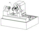
Accompanying drawing 1 is the utility model structural representation.
Accompanying drawing 2-1, Fig. 2-2, Fig. 2-3 are grinding tool different station schematic diagram.
Accompanying drawing 3 is the rotary index device structural representation.
Accompanying drawing 4 is pivot B structural representation.
Accompanying drawing 5 is processing helical gear schematic diagram.
Accompanying drawing 6 is the machining worm schematic diagram.
Accompanying drawing 7 is the keyway schematic diagram on the processing parts.
Accompanying drawing 8 is the periphery schematic diagram on the processing parts.
Accompanying drawing 9 is the gear schematic diagram on the processing parts.
The specific embodiment
Below in conjunction with accompanying drawing, the utility model is described in further detail:
Referring to accompanying drawing 1,2,3,4,5, the utility model Multifunctional molding grinding machine tool, lathe has the lathe bed (8) of a level, in the Y-direction of lathe bed end face, work holder (1) and one group of first horizontal guide rail (73) that axis is parallel to directions X is installed successively; Be provided with the servo drive that driving is held workpiece rotating at described work holder (1); Be equipped with and make the straight-line slide unit of directions X (7) along described the first horizontal guide rail (73) at described the first horizontal guide rail (73), described slide unit (7) is provided with the second horizontal guide rail (63) that is parallel to Y-direction, be equipped with and make the straight-line support of Y-direction (6) along the second horizontal guide rail (63) at described the second horizontal guide rail (63), support (6) is provided with the pivot B(4 that axis is parallel to Y-direction and can rotates around self axis), described pivot B(4) is on the end face of described work holder (1) one end tool spindle case (5) is installed, described tool spindle case (5) is by being located at pivot B(4) the 3rd guide rail (41) of end face diameter direction is installed in pivot B(4) end face, and can be along the 3rd guide rail (41) at pivot B(4) the diametric(al) moving linearly; Be provided with an axis and described pivot B(4 at described tool spindle case (5)) axis vertical and can be around the tool spindle C(51 of self axis rotation);
Described work holder (1) is comprised of the 5th servomotor (12), main shaft (13), anchor clamps (14), tailstock center (15); Described main shaft (13) one ends are installed with the rotor in the 5th servomotor (12), and the other end is equipped with described anchor clamps (14), and the axis of described tailstock center (15) and described main shaft (13) coaxial line are installed;
Also be provided with the first angular encoder (11) on the described work holder (1), described the first angular encoder (11) is electrically connected with described the 5th servomotor (12) control system, the signal of the first angular encoder (11) output is controlled the 5th servomotor (12) rotation amplitude by the 5th servomotor (12) control system, and then control is held the anglec of rotation of workpiece;
Described work holder (1) is provided with one and is used for being installed in tool spindle C(51) on the grinding tool grinding tool trimming device (3) that carries out the moulding finishing;
Behind the described work holder (1), bed piece (8) is provided with a grinding tool storehouse (2), can carry out for lathe the automatic replacing of grinding tool by grinding tool storehouse (2);
Described slide unit (7) is made the directions X rectilinear motion by the first servo drive driving of being located on the lathe bed (8) along the first horizontal guide rail (73); Described the first servo drive is comprised of the first servomotor (72), the first ball wire bar pair (71); Described the first servomotor (72) drives the first ball wire bar pair (71), and then drives described slide unit (7) and make the directions X rectilinear motion along the first horizontal guide rail (73) by being packed in the first feed screw nut on the slide unit (7);
Described support (6) is made the Y-direction rectilinear motion by the second servo drive driving of being located on the described slide unit (7) along the second horizontal guide rail (63); Described the second servo drive is comprised of the second servomotor (62), the second ball wire bar pair (61); Described the second servomotor (62) drives the second ball wire bar pair (61), and then drives described support (6) and make the Y-direction rectilinear motion along the second horizontal guide rail (63) by being packed in the second feed screw nut on the support (6);
Described tool spindle case (5) is by being located at pivot B(4) the 3rd servo drive of end face drives and makes pivot B(4 along the 3rd guide rail (41)) diametric rectilinear motion; Described the 3rd servo drive is comprised of the 3rd servomotor (43), the 3rd ball wire bar pair (42); Described the 3rd servomotor (43) drives the 3rd ball wire bar pair (42), and then drives described tool spindle case (5) and make the diametric rectilinear motion of pivot B along the 3rd guide rail (41) by being packed in the 3rd screw on the tool spindle case (5);
Described pivot B(4) adopt four retaining mechanisms that formed by piston and disk spring to be fixed on the support pivot B(4) freely swing around its axis work at least 180 degree scopes by the 4th servo drive driving of being located in the support (6); Described servo drive is comprised of the 4th servomotor (44), speed change gear (46); Described the 4th servomotor (44) driven wheel speed change gear (46), and then drive pivot B(4) freely swing around its axis work at least 180 degree scopes.
Also be provided with the second angular encoder (45) in described the 4th servo drive, described the second angular encoder (45) is electrically connected with described the 4th servomotor (44) control system, the signal of the second angular encoder (45) output is controlled the 4th servomotor (44) rotation amplitude by the 4th servomotor (44) control system, and then controls pivot B(4) around the angle of its axis oscillating.
Six numerical control axes of coordinates that the utility model has lathe, be defined as respectively X, Y, W, A, B, C axle, adopt the mode layout of 1+5, wherein X, Y, W axle represent grinding tool along directions X, Y-direction and along diametric three rectilinear motions of pivot B, and B, C axle represent the rotation of grinding tool along the swing of pivot B and self along tool spindle C; Therefore, grinding tool has five frees degree.The A axle represents workpiece along the axis of tailstock center (15) or the rotating shaft of described main shaft (13) axis, and workpiece only has one degree of freedom, is exactly the rotation around the A axle.
Accompanying drawing 5, the state of lathe when the demonstration cutter spindle has been installed plunge grinding cutter grinding helical gear.Cylindric spiral gear (101) is installed on work holder (1), and the axis that makes roller gear is positioned on the axis of tailstock center (15), adjust pivot B angle, make plunge grinding instrument angle consistent with the helical angle of cylindric spiral gear, add X, Y, the A axle interlock of man-hour by lathe, grinding tool processes required flank profil profile, process a tooth after, drive device of index turns over certain angle, and grinding tool continues the new flank of tooth of processing.
Accompanying drawing 6 shows the state of lathe when cutter spindle has been installed plunge grinding cutter grinding worm screw.Worm screw (101) is installed on work holder (1), and the axis that makes worm screw is positioned on the axis of tailstock center (15), adjust the B axle, make plunge grinding instrument angle consistent with the helical angle of worm screw, add man-hour by X, Y, the interlock of A axle of lathe, grinding tool processes required flank profil profile.
Accompanying drawing 7-9 shows lathe by after changing different grinding tools (102), the machining state of lathe when the gear on the same part of lathe grinding, spline and periphery.A part by one-step that has gear, spline and periphery to process is installed on work holder (1), and the axis that makes part is positioned on the axis of tailstock center (15), change the angle of grinding tool (102) and adjustment pivot B by lathe, the X that lathe passes through during processing, Y, the interlock of A axle, part by one-step clamping, lathe can process three kinds of different curves on the part.
Claims (10)
1. Multifunctional molding grinding machine tool, it is characterized in that: lathe has the lathe bed of a level, in the Y-direction of lathe bed end face, work holder and one group of first horizontal guide rail that axis is parallel to directions X is installed successively; Be provided with the servo drive that driving is held workpiece rotating at described work holder; Be equipped with and make the straight-line slide unit of directions X along described the first horizontal guide rail at described the first horizontal guide rail, described slide unit is provided with the second horizontal guide rail that is parallel to Y-direction, be equipped with and make the straight-line support of Y-direction along the second horizontal guide rail at described the second horizontal guide rail, support is provided with the pivot B that axis is parallel to Y-direction and can rotates around self axis, described pivot B is on the end face of described work holder one end the tool spindle case is installed, three guide rails assembling of described tool spindle case by being located at pivot B end face diameter direction be at pivot B end face, and can be along the diametric(al) moving linearly of the 3rd guide rail at pivot B; Be provided with an axis at described tool spindle case vertical with described pivot B axis and can be around the tool spindle C of self axis rotation.
2. a kind of Multifunctional molding grinding machine tool according to claim 1, it is characterized in that: described work holder is comprised of the 5th servomotor, main shaft, anchor clamps, tailstock center; Described main shaft one end is fixedly installed on the interior rotor of the 5th servomotor, and the other end is equipped with described anchor clamps, and the axis of described tailstock center and described main shaft coaxial line are installed.
3. a kind of Multifunctional molding grinding machine tool according to claim 2, it is characterized in that: described work holder is provided with the first angular encoder, described the first angular encoder is electrically connected with described the 5th servo control system, the signal of the first angular encoder output is controlled the 5th servomotor rotation amplitude by control system, and then control is held the anglec of rotation of workpiece.
4. a kind of Multifunctional molding grinding machine tool according to claim 3 is characterized in that: described work holder is provided with one and is used for grinding tool trimming device that the grinding tool that is installed on the tool spindle C is carried out the moulding finishing.
5. a kind of Multifunctional molding grinding machine tool according to claim 4 is characterized in that: described slide unit drives and makes the directions X rectilinear motion along the first horizontal guide rail by being located at the first servo drive on the lathe bed; Described the first servo drive is comprised of the first servomotor, the first ball wire bar pair; Described the first driven by servomotor the first ball wire bar pair drives described slide unit and makes the directions X rectilinear motion along the first horizontal guide rail by being packed in the first feed screw nut on the slide unit.
6. a kind of Multifunctional molding grinding machine tool according to claim 5 is characterized in that: described support drives and makes the Y-direction rectilinear motion along the second horizontal guide rail by being located at the second servo drive on the described slide unit; Described the second servo drive is comprised of the second servomotor, the second ball wire bar pair; Described the second driven by servomotor the second ball wire bar pair, and then drive described support and make the Y-direction rectilinear motion along the second horizontal guide rail by being packed in the second feed screw nut on the support.
7. a kind of Multifunctional molding grinding machine tool according to claim 6 is characterized in that: described tool spindle case drives by the 3rd servo drive of being located at pivot B end face and makes the diametric rectilinear motion of pivot B along the 3rd guide rail; Described the 3rd servo drive is comprised of the 3rd servomotor, the 3rd ball wire bar pair; Described the 3rd driven by servomotor the 3rd ball wire bar pair, and then drive described tool spindle case and make the diametric rectilinear motion of pivot B along the 3rd guide rail by being packed in the 3rd screw on the tool spindle case.
8. a kind of Multifunctional molding grinding machine tool according to claim 7, it is characterized in that: described pivot B adopts at least three retaining mechanisms that are comprised of piston and disk spring to be fixed on the support, and pivot B makes 180 degree scopes around its axis and freely swings by being located at the 4th servo drive driving in the support; Described servo drive is comprised of the 4th servomotor, speed change gear; Described the 4th driven by servomotor speed change gear, and then drive pivot B and make 180 degree scopes around its axis and freely swing.
9. a kind of Multifunctional molding grinding machine tool according to claim 8, it is characterized in that: also be provided with the second angular encoder in described the 4th servo drive, described the second angular encoder is electrically connected with described the 4th servo control system, the signal of the second angular encoder output is controlled the 4th servomotor rotation amplitude by the 4th servo control system, and then control pivot B is around the angle of its axis oscillating.
10. the described a kind of Multifunctional molding grinding machine tool of any one according to claim 1-9, it is characterized in that: described grinding tool is dish type vitrified abrasive, dish type skive or dish type cubic boron emery wheel.
Priority Applications (1)
| Application Number | Priority Date | Filing Date | Title |
|---|---|---|---|
| CN 201220355708 CN202716139U (en) | 2012-07-20 | 2012-07-20 | Multifunctional molding grinding machine tool |
Applications Claiming Priority (1)
| Application Number | Priority Date | Filing Date | Title |
|---|---|---|---|
| CN 201220355708 CN202716139U (en) | 2012-07-20 | 2012-07-20 | Multifunctional molding grinding machine tool |
Publications (1)
| Publication Number | Publication Date |
|---|---|
| CN202716139U true CN202716139U (en) | 2013-02-06 |
Family
ID=47617977
Family Applications (1)
| Application Number | Title | Priority Date | Filing Date |
|---|---|---|---|
| CN 201220355708 Expired - Fee Related CN202716139U (en) | 2012-07-20 | 2012-07-20 | Multifunctional molding grinding machine tool |
Country Status (1)
| Country | Link |
|---|---|
| CN (1) | CN202716139U (en) |
Cited By (7)
| Publication number | Priority date | Publication date | Assignee | Title |
|---|---|---|---|---|
| CN102729126A (en) * | 2012-07-20 | 2012-10-17 | 湖南金能达机电科技有限公司 | Multifunctional forming grinding machine tool |
| CN104440426A (en) * | 2014-12-19 | 2015-03-25 | 无锡大龙马数控机床制造有限责任公司 | Headstock device of high-speed internal grinding machine |
| CN104493701A (en) * | 2014-12-19 | 2015-04-08 | 无锡大龙马数控机床制造有限责任公司 | Planar rotary worktable of headstock device |
| CN106312704A (en) * | 2016-08-29 | 2017-01-11 | 广州市昊志机电股份有限公司 | Inner hole machining device |
| CN106563986A (en) * | 2016-10-18 | 2017-04-19 | 江南大学 | Coping and swing and pitching-up control method of multi-deformation casting |
| CN108746873A (en) * | 2018-08-06 | 2018-11-06 | 合肥银泉铸造有限责任公司 | A kind of gear grinding device |
| CN114619345A (en) * | 2022-03-25 | 2022-06-14 | 湖南宇环精密制造有限公司 | Composite grinding machine |
-
2012
- 2012-07-20 CN CN 201220355708 patent/CN202716139U/en not_active Expired - Fee Related
Cited By (8)
| Publication number | Priority date | Publication date | Assignee | Title |
|---|---|---|---|---|
| CN102729126A (en) * | 2012-07-20 | 2012-10-17 | 湖南金能达机电科技有限公司 | Multifunctional forming grinding machine tool |
| CN104440426A (en) * | 2014-12-19 | 2015-03-25 | 无锡大龙马数控机床制造有限责任公司 | Headstock device of high-speed internal grinding machine |
| CN104493701A (en) * | 2014-12-19 | 2015-04-08 | 无锡大龙马数控机床制造有限责任公司 | Planar rotary worktable of headstock device |
| CN106312704A (en) * | 2016-08-29 | 2017-01-11 | 广州市昊志机电股份有限公司 | Inner hole machining device |
| CN106563986A (en) * | 2016-10-18 | 2017-04-19 | 江南大学 | Coping and swing and pitching-up control method of multi-deformation casting |
| CN106563986B (en) * | 2016-10-18 | 2018-11-30 | 江南大学 | A kind of multiform becomes casting reconditioning pendulum and faces upward control method |
| CN108746873A (en) * | 2018-08-06 | 2018-11-06 | 合肥银泉铸造有限责任公司 | A kind of gear grinding device |
| CN114619345A (en) * | 2022-03-25 | 2022-06-14 | 湖南宇环精密制造有限公司 | Composite grinding machine |
Similar Documents
| Publication | Publication Date | Title |
|---|---|---|
| CN202716139U (en) | Multifunctional molding grinding machine tool | |
| CN102198625B (en) | Numerical control universal worm grinder | |
| CN203092346U (en) | Ultra-hard abrasive wheel numerical-control accurate finishing grinder | |
| CN202037476U (en) | Large-scale numerical control gear cutting machine | |
| CN110064799B (en) | Numerical control gear grinding machine for wire gears and wire gear grinding processing method | |
| CN201685166U (en) | Numerically-controlled composite grinding center | |
| CN202264128U (en) | 6-axis linkage numerical-control belt grinding machine for grinding curved surfaces | |
| CN203109692U (en) | Vertical-type numerically-controlled machine tool main shaft swinging device | |
| CN102151909A (en) | Large-scale numerical control gear machining machine tool | |
| CN201711839U (en) | Four-axis-linkage CNC tool grinder | |
| CN103111646B (en) | Combined numerically controlled lathe and power cutter tower thereof | |
| CN206748089U (en) | Bloom carves milling compounding machine bed | |
| CN102310347A (en) | Seven-axis numerical control grinding and shaping equipment for dual conical surface and double enveloping worm | |
| CN102407389A (en) | Face-gear numerical-control gear-grinding machine tool | |
| CN201913522U (en) | Double-cone enveloping worm numerical control grinder | |
| CN103203677A (en) | Numerically controlled grinder special for slewing bearing processing | |
| CN202224774U (en) | Double-cone double-enveloping toroidal worm seven-axis numerical control grinding modification equipment | |
| CN103418852A (en) | Novel efficient numerical control gear grinding machine | |
| CN203228113U (en) | Profile trimming device for grinding wheels of grinder | |
| CN203449103U (en) | Full-automatic numerical control external cylindrical grinding machine | |
| CN201592384U (en) | Ball bearing inner ring raceway grinding device | |
| CN102729126A (en) | Multifunctional forming grinding machine tool | |
| CN202804376U (en) | Precise forming numerical control four-axis linkage inner cyclone milling machine | |
| CN202344053U (en) | Throw-away worm grinding wheel numerical control gear grinding machine | |
| CN205147499U (en) | High -efficient accurate rack grinding machine of numerical control |
Legal Events
| Date | Code | Title | Description |
|---|---|---|---|
| C14 | Grant of patent or utility model | ||
| GR01 | Patent grant | ||
| CF01 | Termination of patent right due to non-payment of annual fee |
Granted publication date: 20130206 Termination date: 20200720 |
|
| CF01 | Termination of patent right due to non-payment of annual fee |