CN203449103U - Full-automatic numerical control external cylindrical grinding machine - Google Patents
Full-automatic numerical control external cylindrical grinding machine Download PDFInfo
- Publication number
- CN203449103U CN203449103U CN201320583419.5U CN201320583419U CN203449103U CN 203449103 U CN203449103 U CN 203449103U CN 201320583419 U CN201320583419 U CN 201320583419U CN 203449103 U CN203449103 U CN 203449103U
- Authority
- CN
- China
- Prior art keywords
- workbench
- lathe bed
- full
- numerical control
- automatic
- Prior art date
- Legal status (The legal status is an assumption and is not a legal conclusion. Google has not performed a legal analysis and makes no representation as to the accuracy of the status listed.)
- Expired - Lifetime
Links
Images
Abstract
The utility model provides a full-automatic numerical control external cylindrical grinding machine, which belongs to the technical field of machines, and solves the problems of an external cylindrical grinding machine in the prior art that the machining range is narrow and the automation degree is low. The full-automatic numerical control external cylindrical grinding machine comprises a lathe bed, a grinding head unit and a worktable, wherein the grinding head unit is arranged on the lathe bed and is provided with a grinding wheel; the worktable is arranged on the lathe bed; two crossed linear guide rails and a cross-shaped sliding platform on the linear guide rails are arranged between the worktable and the lathe bed; the worktable is further provided with a servo motor for driving the worktable to move crosswise and lengthwise along the linear guide rails; the worktable is provided with a clamping structure for clamping a workpiece; the clamping structure and the grinding wheel correspond to each other; the lathe bed is further provided with an automatic feeding unit corresponding to the clamping structure. The full-automatic numerical control external cylindrical grinding machine has the advantages of high automation degree, wide applicable range and the like.
Description
Technical field
The utility model belongs to field of mechanical technique, relates to a kind of cylindrical grinder, particularly a kind of full-automatic numerical control cylindrical grinder.
Background technology
Cylindricalo grinding is an important technique in conventional machining process, not merely can improve the dimensional accuracy of Cylinder Parts, improve the fineness of piece surface, as grinding process, can also serve as the processing of some special material Cylinder Parts of processing, as the Excircle machining of high hardness material, often hardness is high for these parts, fragility is large, be not suitable for processing by techniques such as turning, and cylindricalo grinding can be by changing the material of emery wheel, the parameters such as linear velocity, process it.Although peripheral milling is of many uses, but he has relatively high expectations to operating personnel's, operating personnel's technical merit directly affects precision and the production efficiency of workpiece, and a qualified peripheral milling operator often needs the time of several years to cultivate, Zhe Dui manufacturing enterprise is a problem of relatively having a headache.
Summary of the invention
The purpose of this utility model is to have the problems referred to above for existing technology, has proposed the full-automatic numerical control cylindrical grinder that a kind of flexibility is high, precision is high.
The purpose of this utility model can realize by following technical proposal:
This full-automatic numerical control cylindrical grinder, comprise lathe bed, be fixed at and on its on lathe bed, there is the bistrique unit of emery wheel and be located at the workbench on lathe bed, between described workbench and lathe bed, be provided with the line slideway of two right-angled intersections and be located at the cross slid platform on line slideway, on described workbench, be also provided with for driving workbench along the servomotor of the horizontal and vertical movement of line slideway, it is characterized in that, on described workbench, there is the clamp structure for holding workpiece, the setting corresponding with emery wheel of described clamp structure, on described lathe bed, also there is the automatic charging unit with the corresponding setting of this clamp structure.
During work, automatic charging unit is delivered to clamp structure place by workpiece, and by clamp structure, by piece-holder, emery wheel is processed processing to workpiece.Workbench can, along the horizontal and vertical movement of lathe bed, be realized workpiece in feeding axial and radially; Workbench can rotate in horizontal plane, meets the needs of circular cone class part grinding.Nitrogen damping unit is all housed in movable workbench direction, increases table feed stability and reduce resetting error.
In above-mentioned full-automatic numerical control cylindrical grinder, described workbench is provided with gathering sill, above-mentioned clamp structure comprises by T shape screw is located at the headstock and the tailstock on workbench, on the described headstock, there is thimble one, on described tailstock, there is the thimble two being oppositely arranged with thimble one, on described tailstock, be also provided with and drive the flexible cylinder of thimble two.
In above-mentioned full-automatic numerical control cylindrical grinder, on described tailstock, be also provided with grinding wheel dressing pen and by the automatic measuring unit of hydraulic oil cylinder driving, described automatic measuring unit is controlled by PLC.
Tailstock is arranged on workbench, by T shape screw, is connected with workbench, can on workbench, move along gathering sill direction, can realize the function of thimble two automatic telescopics by cylinder.Automatic measuring unit has been installed at tailstock top, automatically measuring unit, under the driving of oil cylinder, can stretch, and during work, measuring unit reaches measuring position and carries out on-line measurement, after grinding, automatically retract to home, automatic charging unit carries out material loading operation.Finishing pen is installed on tailstock, by movable workbench, realizes the object of trimming wheel.
The headstock is arranged on the workbench other end, by T shape screw, be connected with workbench, can on workbench, move along gathering sill direction, the headstock adopts thimble one fixed to improve rigidity, reduce the workpiece machining error that headstock rotation precision error causes, headstock top is provided with stirs head, and this is stirred head and is connected with servomotor by Timing Belt, can realize stepless time adjustment and optional position is accurately located.
In above-mentioned full-automatic numerical control cylindrical grinder, the below of described automatic charging unit is provided with automatic blanking unit.
Compared with prior art, this full-automatic numerical control cylindrical grinder has the following advantages:
Bistrique unit is directly fixed on lathe bed, improves form accuracy and the surface smoothness of workpiece; Workbench can horizontal and vertical movement in horizontal plane, realize workpiece in feeding axial and radially, damping unit has all been installed in table feed direction, more stable while making table feed, and effectively reduced due to the long-term problem of using the repetitive positioning accuracy error of bringing of ball-screw; Automatically the size at the automatic measuring workpieces grinding of measuring unit position to digital control system feedback signal, stops procedure and falls back on home after workpiece size arrives within the scope of specified tolerances, prepares the grinding of next part workpiece; By automatic charging unit material loading, improved work efficiency rate, reduce workman's labour intensity, reduction labour cost.
Accompanying drawing explanation
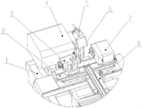
Fig. 1 is the structural representation of a kind of preferred embodiment of providing of the utility model.
In figure, 1, lathe bed; 2, workbench; 3, tailstock; 4, bistrique unit; 5, grinding wheel dressing pen; 6, automatic measuring unit; 7, the headstock; 8, automatic charging unit.
The specific embodiment
Be below specific embodiment of the utility model by reference to the accompanying drawings, the technical solution of the utility model is further described, but the utility model be not limited to these embodiment.
Full-automatic numerical control cylindrical grinder as shown in Figure 1, comprise lathe bed 1, be fixed at and on its on lathe bed 1, there is the bistrique unit 4 of emery wheel and be located at the workbench 2 on lathe bed 1, between workbench 2 and lathe bed 1, be provided with the line slideway of two right-angled intersections and be located at the cross slid platform on line slideway, on workbench 2, be also provided with for driving workbench 2 along the servomotor of the horizontal and vertical movement of line slideway, as shown in Figure 1, on workbench 2, there is the clamp structure for holding workpiece, clamp structure setting corresponding with emery wheel, on lathe bed 1, also there is the automatic charging unit 8 with the corresponding setting of this clamp structure.
During work, automatic charging unit 8 is delivered to clamp structure place by workpiece, and by clamp structure, by piece-holder, emery wheel is processed processing to workpiece.Workbench 2 can, along the horizontal and vertical movement of lathe bed 1, be realized workpiece in feeding axial and radially; Workbench 2 can rotate in horizontal plane, meets the needs of circular cone class part grinding.On workbench 2 moving directions, nitrogen damping unit is all housed, increases workbench 2 feeding stability and reduce resetting error.
Concrete, as shown in Figure 1, on workbench 2, be provided with gathering sill, clamp structure comprises by T shape screw is located at the headstock 7 and the tailstock 3 on workbench 2, on the headstock 7, there is thimble one, on tailstock 3, there is the thimble two being oppositely arranged with thimble one, on tailstock 3, be also provided with and drive the flexible cylinder of thimble two.As shown in Figure 1, on tailstock 3, be also provided with grinding wheel dressing pen 5 and by the automatic measuring unit 6 of hydraulic oil cylinder driving, measuring unit 6 is controlled by PLC automatically.
Tailstock 3 is arranged on workbench 2, by T shape screw, is connected with workbench 2, can on workbench 2, move along gathering sill direction, can realize the function of thimble two automatic telescopics by cylinder.Automatic measuring unit 6 has been installed at tailstock 3 tops, automatically measuring unit 6, under the driving of oil cylinder, can stretch, and during work, measuring unit reaches measuring position and carries out on-line measurement, after grinding, automatically retract to home, automatic charging unit 8 carries out material loading operation.Finishing pen is installed on tailstock 3, by workbench 2, moves, realize the object of trimming wheel.
The headstock 7 is arranged on workbench 2 other ends, by T shape screw, be connected with workbench 2, can on workbench 2, move along gathering sill direction, the headstock 7 adopts thimble one fixed to improve rigidity, reduce the workpiece machining error that the headstock 7 rotation precision errors cause, the headstock 7 tops are provided with stirs head, and this is stirred head and is connected with servomotor by Timing Belt, can realize stepless time adjustment and optional position is accurately located.
In the present embodiment, below automatic charging unit 8, be provided with automatic blanking unit.
Specific embodiment described herein is only to the explanation for example of the utility model spirit.The utility model person of ordinary skill in the field can make various modifications or supplements or adopt similar mode to substitute described specific embodiment, but can't depart from spirit of the present utility model or surmount the defined scope of appended claims.
Claims (4)
1. a full-automatic numerical control cylindrical grinder, comprise lathe bed (1), be fixed on its on lathe bed (1) and there is the bistrique unit (4) of emery wheel and be located at the workbench (2) on lathe bed (1), between described workbench (2) and lathe bed (1), be provided with the line slideway of two right-angled intersections and be located at the cross slid platform on line slideway, on described workbench (2), be also provided with for driving workbench (2) along the servomotor of the horizontal and vertical movement of line slideway, it is characterized in that, described workbench has the clamp structure for holding workpiece on (2), the setting corresponding with emery wheel of described clamp structure, on described lathe bed (1), also there is the automatic charging unit (8) with the corresponding setting of this clamp structure.
2. full-automatic numerical control cylindrical grinder according to claim 1, it is characterized in that, described workbench (2) is provided with gathering sill, above-mentioned clamp structure comprises by T shape screw is located at the headstock (7) and the tailstock (3) on workbench (2), the described headstock has thimble one on (7), on described tailstock (3), there is the thimble two being oppositely arranged with thimble one, on described tailstock (3), be also provided with and drive the flexible cylinder of thimble two.
3. full-automatic numerical control cylindrical grinder according to claim 2, is characterized in that, is also provided with grinding wheel dressing pen (5) and by the automatic measuring unit (6) of hydraulic oil cylinder driving on described tailstock (3).
4. according to the full-automatic numerical control cylindrical grinder described in claim 1 or 2 or 3, it is characterized in that, the below of described automatic charging unit (8) is provided with automatic blanking unit.
Priority Applications (1)
| Application Number | Priority Date | Filing Date | Title |
|---|---|---|---|
| CN201320583419.5U CN203449103U (en) | 2013-09-22 | 2013-09-22 | Full-automatic numerical control external cylindrical grinding machine |
Applications Claiming Priority (1)
| Application Number | Priority Date | Filing Date | Title |
|---|---|---|---|
| CN201320583419.5U CN203449103U (en) | 2013-09-22 | 2013-09-22 | Full-automatic numerical control external cylindrical grinding machine |
Publications (1)
| Publication Number | Publication Date |
|---|---|
| CN203449103U true CN203449103U (en) | 2014-02-26 |
Family
ID=50129006
Family Applications (1)
| Application Number | Title | Priority Date | Filing Date |
|---|---|---|---|
| CN201320583419.5U Expired - Lifetime CN203449103U (en) | 2013-09-22 | 2013-09-22 | Full-automatic numerical control external cylindrical grinding machine |
Country Status (1)
| Country | Link |
|---|---|
| CN (1) | CN203449103U (en) |
Cited By (5)
| Publication number | Priority date | Publication date | Assignee | Title |
|---|---|---|---|---|
| CN104057370A (en) * | 2014-06-11 | 2014-09-24 | 洛阳高精机械制造有限公司 | High-precision numerical control cylindrical roller fine grinding and ultra-fine grinding integral machine tool |
| CN104440427A (en) * | 2014-12-10 | 2015-03-25 | 苏州市诚品精密机械有限公司 | Multiple-degree-of-freedom cylindrical grinding device |
| CN106736918A (en) * | 2017-02-06 | 2017-05-31 | 江苏三叶环保机械制造有限公司 | A kind of semi-automatic disk class polishing emery wheel machine equipment |
| CN108217188A (en) * | 2018-02-08 | 2018-06-29 | 东莞市德威精密机械有限公司 | Feeder is detected outside full-automatic line |
| CN113547455A (en) * | 2021-07-30 | 2021-10-26 | 东莞市浩源智能机械有限公司 | Offline measuring mechanism for grinding machine |
-
2013
- 2013-09-22 CN CN201320583419.5U patent/CN203449103U/en not_active Expired - Lifetime
Cited By (8)
| Publication number | Priority date | Publication date | Assignee | Title |
|---|---|---|---|---|
| CN104057370A (en) * | 2014-06-11 | 2014-09-24 | 洛阳高精机械制造有限公司 | High-precision numerical control cylindrical roller fine grinding and ultra-fine grinding integral machine tool |
| CN104057370B (en) * | 2014-06-11 | 2016-05-18 | 洛阳高精机械制造有限公司 | A kind of high precision numerical control cylindrical roller fine grinding superfinishing integrated machine tool |
| CN104440427A (en) * | 2014-12-10 | 2015-03-25 | 苏州市诚品精密机械有限公司 | Multiple-degree-of-freedom cylindrical grinding device |
| CN106736918A (en) * | 2017-02-06 | 2017-05-31 | 江苏三叶环保机械制造有限公司 | A kind of semi-automatic disk class polishing emery wheel machine equipment |
| CN106736918B (en) * | 2017-02-06 | 2018-08-07 | 江苏三叶环保机械制造有限公司 | A kind of semi-automatic disk class polishing grinding wheel machine equipment |
| CN108217188A (en) * | 2018-02-08 | 2018-06-29 | 东莞市德威精密机械有限公司 | Feeder is detected outside full-automatic line |
| CN113547455A (en) * | 2021-07-30 | 2021-10-26 | 东莞市浩源智能机械有限公司 | Offline measuring mechanism for grinding machine |
| CN113547455B (en) * | 2021-07-30 | 2022-11-18 | 东莞市浩源智能机械有限公司 | Offline measuring mechanism for grinding machine |
Similar Documents
| Publication | Publication Date | Title |
|---|---|---|
| CN201685166U (en) | Numerically-controlled composite grinding center | |
| CN105437032A (en) | Ultrahigh-precision numerically-controlled non-circular curved surface composite grinder | |
| CN203449103U (en) | Full-automatic numerical control external cylindrical grinding machine | |
| CN105563246A (en) | Numerical-control deep hole grinder | |
| CN101983839A (en) | Numerically controlled grinder | |
| CN108788959A (en) | A kind of vertical grinder for the conical surface and taper hole grinding | |
| CN106001619B (en) | Device for machining spherical surface | |
| CN101811277A (en) | Grinding device and using method thereof for ball bearing inner ring raceway | |
| CN202716139U (en) | Multifunctional molding grinding machine tool | |
| CN101829942A (en) | Machining center for polishing and grinding square rod | |
| CN104002208A (en) | Vertical type cylindrical grinding machine | |
| CN103252689A (en) | High-precision numerical control internal grinding machine tool | |
| CN203228113U (en) | Profile trimming device for grinding wheels of grinder | |
| CN110539221A (en) | Grinding synchronous deburring mechanism and method suitable for high-precision servo valve core | |
| CN202185813U (en) | Double-end grinding shaft five-axle grinding center | |
| CN113814814A (en) | Multifunctional numerical control cylindrical grinding machine | |
| CN202804880U (en) | Four-axis vertical numerical-control grinding center | |
| CN201960433U (en) | Numerically controlled grinder | |
| CN201592384U (en) | Ball bearing inner ring raceway grinding device | |
| CN203843614U (en) | Numerical control moving planer type double grinding head circle platform surface grinding machine | |
| CN204770998U (en) | Numerical control internal thread grinding center | |
| CN104625885A (en) | Master-slave gantry lathe bed structure with double Z axes | |
| CN201922256U (en) | Numerical control engraving machine for special cutting die | |
| CN104044216A (en) | Cylindrical stone profiling machine | |
| CN110919468A (en) | Novel wriggling grinding machine |
Legal Events
| Date | Code | Title | Description |
|---|---|---|---|
| C14 | Grant of patent or utility model | ||
| GR01 | Patent grant | ||
| CP01 | Change in the name or title of a patent holder |
Address after: 317502 Tangxia Industrial Zone, Xinhe Town, Wenling City, Taizhou City, Zhejiang Province Patentee after: Beiping machine tool (Zhejiang) Co.,Ltd. Address before: 317502 Tangxia Industrial Zone, Xinhe Town, Wenling City, Taizhou City, Zhejiang Province Patentee before: TAIZHOU BEIPING MACHINE TOOL Co.,Ltd. |
|
| CP01 | Change in the name or title of a patent holder | ||
| CX01 | Expiry of patent term |
Granted publication date: 20140226 |
|
| CX01 | Expiry of patent term |