CN202185813U - Double-end grinding shaft five-axle grinding center - Google Patents
Double-end grinding shaft five-axle grinding center Download PDFInfo
- Publication number
- CN202185813U CN202185813U CN2011201801901U CN201120180190U CN202185813U CN 202185813 U CN202185813 U CN 202185813U CN 2011201801901 U CN2011201801901 U CN 2011201801901U CN 201120180190 U CN201120180190 U CN 201120180190U CN 202185813 U CN202185813 U CN 202185813U
- Authority
- CN
- China
- Prior art keywords
- grinding
- main shaft
- grinding wheel
- workpiece
- sliding plate
- Prior art date
- Legal status (The legal status is an assumption and is not a legal conclusion. Google has not performed a legal analysis and makes no representation as to the accuracy of the status listed.)
- Expired - Fee Related
Links
Images

Abstract
A double-end grinding shaft five-axle grinding center comprises a lathe body which is provided with an X-direction sliding plate, an X-direction sliding plate driving device, a vertical post capable of sliding along a Y axis and a vertical post driving device, a workpiece main shaft box is installed on the X-direction sliding plate, and internally provided with a workpiece main shaft and a main shaft driving device, the vertical post is provided with a Z-direction sliding plate capable of sliding along the Z-axis direction, and a Z-direction sliding plate driving device, the Z-direction sliding plate is provided with a rotatable grinding wheel main shaft box which is internally provided with a grinding wheel main shaft and a grinding wheel main shaft driving device, the grinding wheel main shaft is a double-end main shaft, and grinding wheels are installed at two ends of the grinding wheel main shaft. In the utility model, the two grinding wheels are installed at two ends of the main shaft, and in one-time clamping, two-time grinding can be completed by only adjusting the grinding wheel shaft, so that the clamping time of the workpiece can be shortened, and the processing efficiency is improved on the one hand, and the processing precision of the workpiece can be improved on the other hand.
Description
Technical field
The utility model relates to a kind of five grinding centers.
Background technology
Grinding is used comparatively extensive, is one of precision machined main method of machine parts.And the high precision numerical control equipment for grinding is the high-precision processing equipment that precision optical machinery industry such as military project, space flight, cutter, measurer, lathe manufacturing are badly in need of, and is the important assurance means of the manufacturing industry accuracy of manufacture, is called as " machine tool in the processing machine tool ".Wherein, the five-shaft numerical control grinding center that has three rectilinear coordinates and two revolution coordinates is the grinding lathe of a kind of high accuracy, high automation, is applied in the grinding production by increasing.But when known up to now five-shaft numerical control grinding center carried out grinding to workpiece, correct grinding and corase grind operation were all separately carried out, and so just need repeatedly carry out clamping, and efficient is lower on the one hand, has also influenced machining accuracy on the other hand.
The utility model content
In view of the above-mentioned shortcoming of prior art, the technical problem that the utility model will solve provides the grinding center that a kind of working (machining) efficiency is high, machining accuracy is high.
The utility model solves the technical scheme that its technical problem adopted:
Five grinding centers of a kind of both-end mill axle; Comprise lathe bed, be equipped with on the said lathe bed X to slide plate, X to slide board drive device, the column and the column drive unit that can slide along the Y axle, said X is equipped with workpiece spindle box on slide plate; Work spindle and main shaft driving device are installed in the said workpiece spindle box; Said column be provided with the Z that can slide along Z-direction to slide plate and Z to slide board drive device, said Z is equipped with rotatable grinding wheel spindle case on slide plate, grinding wheel spindle and grinding wheel spindle drive unit are installed in the said grinding wheel spindle case; Said grinding wheel spindle is the both-end main shaft, and its two ends all are equipped with emery wheel.
The technical scheme of the utility model also can be done following improvement:
As the improvement of technique scheme, said grinding wheel spindle is electric main shaft.
Further improvement as technique scheme also comprises a dresser, and it is installed on by the workpiece spindle box.
Further improvement as technique scheme also comprises a tailstock, and it is slidingly mounted on X on slide plate.
As the further improvement of technique scheme, said work spindle is electric main shaft.
With respect to prior art; The beneficial effect of the utility model is: the utility model is installed two emery wheels through the two ends at a main shaft; Only need turn grinding wheel spindle can accomplish twice grinding in a clamping; Reduce the clamping time of workpiece on the one hand, improved working (machining) efficiency, can improve the machining accuracy of workpiece on the other hand.
Below will combine accompanying drawing that the technique effect of design, concrete structure and the generation of the utility model is described further, with purpose, characteristic and the effect of understanding the utility model fully.
Description of drawings
Fig. 1 is the perspective view of an embodiment of the utility model grinding center;
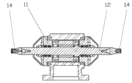
Fig. 2 is the grinding wheel spindle box structure sketch map of grinding center among Fig. 1.
The specific embodiment
The basic design of the utility model method is: the two ends at grinding wheel spindle all are provided with emery wheel; Like this, only need turn grinding wheel spindle can accomplish twice grinding in a clamping, for example accomplishes once corase grind respectively and once finish grindes; Like this; Reduce the clamping time of workpiece on the one hand, improved working (machining) efficiency, can improve the machining accuracy of workpiece on the other hand.
Fig. 1 and Fig. 2 show the structure of the utility model grinding center and grinding wheel spindle case respectively; This grinding center comprises lathe bed 1; Be equipped with on the said lathe bed 1 X to slide plate 2, X to slide board drive device 3, the column 4 and the column drive unit 5 that can slide along the Y axle; Said X 2 is equipped with workpiece spindle box 6 on slide plate, in the said workpiece spindle box 6 work spindle 7 and main shaft driving device are installed, said column 4 be provided with the Z that can slide along Z-direction to slide plate 9 and Z to slide board drive device 10; Said Z is equipped with rotatable grinding wheel spindle case 11 on slide plate 9; Grinding wheel spindle 12 and grinding wheel spindle drive unit are installed in the said grinding wheel spindle case 11, and said grinding wheel spindle is the both-end main shaft, and its two ends all are equipped with emery wheel 14.
In the present embodiment, said grinding wheel spindle 12 is all preferably selected electric main shaft for use with work spindle 7.
In the present embodiment, also preferably include a dresser 15, it is other that it is installed on workpiece spindle box 6, can be conveniently the emery wheel 14 of needs correction be carried out the back work that size, shape, geometric angle etc. are repaired.
In order to cooperate 6 pairs of workpiece of workpiece spindle box to position and support, also preferably include a tailstock 16 in the present embodiment, it is slidingly mounted on X on slide plate 2.
In addition, said X to slide board drive device 3 comprise be arranged on before on the lathe bed 1 X to servomotor and with X to slide plate 2 transmissions cooperate X to ball screw; Said column drive unit 5 comprise the Y that is arranged on the lathe bed 1 to servomotor and the Y that cooperates with column 4 transmissions to ball screw; Said Z comprises that to slide board drive device 10 Z that the Z that is arranged on the column 4 cooperates to slide plate 9 transmissions to servomotor with Z is to ball screw.This ball wire rod-type kind of drive is known, is used always by those skilled in that art; And grinding wheel spindle case 11 is also known by those skilled in that art around the embodiment of C axle rotation; And; Those skilled in the art also can make the various distortion that are equal to these drive units, gives unnecessary details no longer one by one at this.
Claims (5)
1. both-end grinds five grinding centers of axle; Comprise lathe bed, be equipped with on the said lathe bed X to slide plate, X to slide board drive device, the column and the column drive unit that can slide along the Y axle, said X is equipped with workpiece spindle box on slide plate; Work spindle and main shaft driving device are installed in the said workpiece spindle box; Said column be provided with the Z that can slide along Z-direction to slide plate and Z to slide board drive device, said Z is equipped with rotatable grinding wheel spindle case on slide plate, grinding wheel spindle and grinding wheel spindle drive unit are installed in the said grinding wheel spindle case; It is characterized in that: said grinding wheel spindle is the both-end main shaft, and its two ends all are equipped with emery wheel.
2. five grinding centers of both-end mill axle according to claim 1, it is characterized in that: said grinding wheel spindle is electric main shaft.
3. five grinding centers of both-end mill axle according to claim 1 and 2, it is characterized in that: also comprise a dresser, it is installed on by the workpiece spindle box.
4. five grinding centers of both-end mill axle according to claim 1 and 2, it is characterized in that: also comprise a tailstock, it is slidingly mounted on X on slide plate.
5. five grinding centers of both-end mill axle according to claim 4, it is characterized in that: said work spindle is electric main shaft.
Priority Applications (1)
| Application Number | Priority Date | Filing Date | Title |
|---|---|---|---|
| CN2011201801901U CN202185813U (en) | 2011-05-31 | 2011-05-31 | Double-end grinding shaft five-axle grinding center |
Applications Claiming Priority (1)
| Application Number | Priority Date | Filing Date | Title |
|---|---|---|---|
| CN2011201801901U CN202185813U (en) | 2011-05-31 | 2011-05-31 | Double-end grinding shaft five-axle grinding center |
Publications (1)
| Publication Number | Publication Date |
|---|---|
| CN202185813U true CN202185813U (en) | 2012-04-11 |
Family
ID=45917283
Family Applications (1)
| Application Number | Title | Priority Date | Filing Date |
|---|---|---|---|
| CN2011201801901U Expired - Fee Related CN202185813U (en) | 2011-05-31 | 2011-05-31 | Double-end grinding shaft five-axle grinding center |
Country Status (1)
| Country | Link |
|---|---|
| CN (1) | CN202185813U (en) |
Cited By (6)
| Publication number | Priority date | Publication date | Assignee | Title |
|---|---|---|---|---|
| CN104942707A (en) * | 2014-03-25 | 2015-09-30 | 昆山艾思迪机械科技有限公司 | Six-axis five-linkage tool grinding machine with automatic feeding and discharging functions |
| CN104942705A (en) * | 2014-03-25 | 2015-09-30 | 昆山艾思迪机械科技有限公司 | Material mounting assembly and grinding machine comprising the same |
| CN104942686A (en) * | 2014-03-25 | 2015-09-30 | 昆山艾思迪机械科技有限公司 | Six-axis five-linkage tool grinding machine |
| CN104942713A (en) * | 2014-03-25 | 2015-09-30 | 昆山艾思迪机械科技有限公司 | Transmission mechanism for six-axis five-linkage tool grinding machine |
| CN108214125A (en) * | 2016-12-22 | 2018-06-29 | 湖南中大创远数控装备有限公司 | Cutterhead grinding attachment |
| CN108247149A (en) * | 2018-03-21 | 2018-07-06 | 温岭市宇弘机械设备有限公司 | Numerical control rotation divides milling machine |
-
2011
- 2011-05-31 CN CN2011201801901U patent/CN202185813U/en not_active Expired - Fee Related
Cited By (6)
| Publication number | Priority date | Publication date | Assignee | Title |
|---|---|---|---|---|
| CN104942707A (en) * | 2014-03-25 | 2015-09-30 | 昆山艾思迪机械科技有限公司 | Six-axis five-linkage tool grinding machine with automatic feeding and discharging functions |
| CN104942705A (en) * | 2014-03-25 | 2015-09-30 | 昆山艾思迪机械科技有限公司 | Material mounting assembly and grinding machine comprising the same |
| CN104942686A (en) * | 2014-03-25 | 2015-09-30 | 昆山艾思迪机械科技有限公司 | Six-axis five-linkage tool grinding machine |
| CN104942713A (en) * | 2014-03-25 | 2015-09-30 | 昆山艾思迪机械科技有限公司 | Transmission mechanism for six-axis five-linkage tool grinding machine |
| CN108214125A (en) * | 2016-12-22 | 2018-06-29 | 湖南中大创远数控装备有限公司 | Cutterhead grinding attachment |
| CN108247149A (en) * | 2018-03-21 | 2018-07-06 | 温岭市宇弘机械设备有限公司 | Numerical control rotation divides milling machine |
Similar Documents
| Publication | Publication Date | Title |
|---|---|---|
| CN201711819U (en) | Five-shaft linkage double-end grinding shaft numerical control tool grinding machine | |
| CN201685166U (en) | Numerically-controlled composite grinding center | |
| CN202185813U (en) | Double-end grinding shaft five-axle grinding center | |
| CN105437032A (en) | Ultrahigh-precision numerically-controlled non-circular curved surface composite grinder | |
| CN201998021U (en) | Numerical control grinder | |
| CN202716139U (en) | Multifunctional molding grinding machine tool | |
| CN105751044A (en) | Double-cutter grinding machine tool | |
| CN204893598U (en) | Processing grinding machine of taper hole | |
| CN101829942A (en) | Machining center for polishing and grinding square rod | |
| CN203900648U (en) | Internal thread grinding machine for ball screw nut | |
| CN201907050U (en) | Multi-spindle grinding device for grinding machining center | |
| CN205600473U (en) | Numerical control hole external tooth grinding machine | |
| CN203449103U (en) | Full-automatic numerical control external cylindrical grinding machine | |
| CN202804880U (en) | Four-axis vertical numerical-control grinding center | |
| CN204725327U (en) | A kind of multi-thread emery wheel compound automatic trimming device | |
| CN203680061U (en) | Numerical control grinding wheel dresser | |
| CN203611078U (en) | Belt sander | |
| CN102756335B (en) | High-precision efficient stepped grinding wheel dresser | |
| CN104625885A (en) | Master-slave gantry lathe bed structure with double Z axes | |
| CN204471113U (en) | The two portal lathe bed structure of Z axis of master-slave mode | |
| CN101579812A (en) | Method and processing center for external thread rotary milling and grinding | |
| CN207402222U (en) | Digital control vertical gear milling machine | |
| CN203509844U (en) | Synchronous efficient grinding machine tool with off-axis curve-surface double abrasion wheels | |
| CN203471513U (en) | Blisk polishing machining and measuring integrated device | |
| CN203197714U (en) | Numerical control grinding machine special for machining slewing bearing |
Legal Events
| Date | Code | Title | Description |
|---|---|---|---|
| C14 | Grant of patent or utility model | ||
| GR01 | Patent grant | ||
| CF01 | Termination of patent right due to non-payment of annual fee | ||
| CF01 | Termination of patent right due to non-payment of annual fee |
Granted publication date: 20120411 Termination date: 20200531 |