CN202534923U - Butt socket welding module of cable connector automatic processing and welding assembly machine - Google Patents
Butt socket welding module of cable connector automatic processing and welding assembly machine Download PDFInfo
- Publication number
- CN202534923U CN202534923U CN2012201394261U CN201220139426U CN202534923U CN 202534923 U CN202534923 U CN 202534923U CN 2012201394261 U CN2012201394261 U CN 2012201394261U CN 201220139426 U CN201220139426 U CN 201220139426U CN 202534923 U CN202534923 U CN 202534923U
- Authority
- CN
- China
- Prior art keywords
- welding
- connector
- material road
- defeated material
- jaw
- Prior art date
- Legal status (The legal status is an assumption and is not a legal conclusion. Google has not performed a legal analysis and makes no representation as to the accuracy of the status listed.)
- Expired - Fee Related
Links
Images


Abstract
The utility model discloses a butt socket welding module of a cable connector automatic processing and welding assembly machine. The butt socket welding module of the cable connector automatic processing and welding assembly machine comprises a butt socket device, a welding device, a clamping jaw blanking device and a tin paste injecting device which is used for carrying out tin paste injecting on a connector. A conveying device for conveying a jig is arranged between the clamping jaw blanking device and a clamping jaw feeding device. The butt socket device and the welding device are successively arranged along the feeding direction of the conveying device. According to the utility model, by cooperatively using the tin paste injecting device, the butt socket device, the welding device and the clamping jaw blanking device, the welding assembly process of a cable and the connector is automatically completed, thus the traditional way of manual welding assembly is replaced; the core wire of the cable always keeps straight in an assembly welding process; the quality problems of dry welding, welding negligence and short circuit are eliminated, wherein the quality problems appear when the cable is connected with the connector; unmanned automatic welding assembly is realized; the production efficiency of products is effectively improved; and enterprises are provided with economic benefits.
Description
Technical field
The utility model relates to electric connector welding assembly apparatus field technology, refer in particular to a kind of wire and cable connector process automatically the soldering group installation to inserting the welding module.
Background technology
The existing data cable that is applied to connect electronic installations such as notebook, digital camera, mobile phone all is made up of the number of metal heart yearn; When cable connects other electronic installation through terminal; At first need remove the peel the insulated hull of cable, then to heart yearn carry out zinc-plated, utilize manual welding or pulse welding equipment that the cable heart yearn is welded on the connector after technology such as cutting.
Along with the IT industry product develops towards " frivolous, short and small " day by day; Simultaneously from strength to strength to functional requirement; All parts also must be done ultra-fine and small processing thus; The used cable of data wire also becomes thinner 34AWG, 36AWG, 40AWG and 42 AWG by 28AWG (U.S.'s wire gauge), 30AWG, is removing the peel, cuts, causing terminal rosin joint to occur, leaks bad qualities such as weldering and short circuit, obviously because of heart yearn bending and distortion easily during zinc-plated, welding; The traditional hand processing technology can't satisfy the processing assembling and the welding of present tiny cable, and production efficiency, product quality are low.
The utility model content
In view of this; The utility model is to the disappearance of prior art existence; Its main purpose provide a kind of wire and cable connector process automatically soldering group installation to inserting the welding module, it can effectively solve the welding assembly that existing employings craft carries out wire and cable connector and have low, the ropy problem of production efficiency.
For realizing above-mentioned purpose, the utility model adopts following technical scheme:
A kind of wire and cable connector process automatically soldering group installation to inserting the welding module; It is arranged at wire and cable connector and processes automatically on the frame of soldering group installation, includes plug device, welder, jaw blanking device and is used for connector is carried out the some tin device of a tin; Be provided with the conveyer that is used to transmit tool between this jaw blanking device and the jaw pay-off, this sets gradually plug device and the welder direction along the feeding of conveyer.
As a kind of preferred version; Further include the tool apparatus for shaping; This tool apparatus for shaping is positioned at the input of conveyer; The tool apparatus for shaping includes and can be arranged at the adjustable shelf on the frame versatilely and can be arranged at the last dressing stick and following dressing stick on this adjustable shelf up and downly in front and back, is provided with first to this adjustable shelf, last dressing stick and following dressing stick and drives cylinder body.
As a kind of preferred version, further include vibrating disc feeding device, the first defeated material road and the second defeated material road, this first defeated material road is communicated with the output of vibrating disc feeding device, and this second defeated material road and the first defeated material road laterally arrange; This tin device includes connector positioning seat and some tin head, and this connector positioning seat can be arranged between the first defeated material road and the second defeated material road front and back versatilely, is provided with the rotary cylinder of drive connector positioning seat upset to this connector positioning seat; This tin head can laterally reach the top that vertically is provided with and is positioned at the connector positioning seat versatilely.
As a kind of preferred version, the other branch spacing mechanism that is provided with of the side in the said second defeated material road, this minute spacing mechanism include and can be arranged side by side the resilient fingers on this movable block along movable back and forth movable block and at least two lateral separations of bearing of trend, the second defeated material road; This includes at least two pairs of first jaws that are used to clamp connector to plug device, is arranged at the top in the second defeated material road before and after this first jaw can reach up and down versatilely.
As a kind of preferred version; Said welder includes fixed mount and can be arranged at the last heat welded assembly and following heat welded assembly on this fixed mount up and downly; Should go up the heat welded assembly and all have the head of heating with following heat welded assembly, and should go up be provided with between heat welded assembly and the following heat welded assembly can before and after activity be used for a brush that cleans of heating.
As a kind of preferred version, said this jaw blanking device includes horizontal slide rail, transverse slider and at least two pairs second jaws; This horizontal sliding rail frame is located on the frame; This transverse slider can laterally be arranged on the horizontal slide rail versatilely, is provided with to this transverse slider and drives this transverse slider along walking crosswise the second driving cylinder body that guide rail moves around; This two couple second jaw all is installed on the transverse slider through a vertical slide block at interval side by side, and this vertical slide block can be installed on the transverse slider up and downly.
The utility model compared with prior art has tangible advantage and beneficial effect, particularly, can be known by technique scheme:
One, through cooperate to utilize a some tin device, to plug device, welder and jaw blanking device; Accomplish automatic welding assembly operation to cable and connector; Replace the mode of the manual welding assembling of tradition with this; Help making the heart yearn of cable in the process of assembling welding, to remain rosin joint straight, that occur when elimination is connected with connector, leak quality problem such as weldering and short circuit; And realize unmanned automation welding assembly, effectively improved production efficiency of products, for enterprise brings more economic benefit.
Two, through between last heat welded assembly and following heat welded assembly, be provided with can before and after movable brush; Being beneficial to this brush cleans the head of heating; Timely and effectively waste materials such as scruff are cleared up away; Avoid waste materials such as scruff that welding is impacted, thereby improved the welding quality between cable and the connector.
Three, its jaw blanking device is through being provided with at least two pairs second jaws; Make and tool to be picked up when putting into welder and welding when a pair of second jaw wherein; This another can carry out blanking to the tool of accomplishing welding to second jaw, thereby can further improve operating efficiency.
Be architectural feature and the effect of more clearly setting forth the utility model, come the utility model is elaborated below in conjunction with accompanying drawing and specific embodiment.
Description of drawings
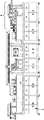
Fig. 1 is the front schematic view of critical piece in the preferred embodiment of the utility model;
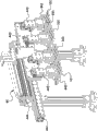
Fig. 2 is to inserting the enlarged diagram of welding module in the preferred embodiment of the utility model;
Fig. 3 is the enlarged diagram of tool apparatus for shaping in the preferred embodiment of the utility model;
Fig. 4 is to inserting the local enlarged diagram of welding module in the preferred embodiment of the utility model;
Fig. 5 is another view of Fig. 4;
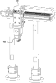
Fig. 6 is the local enlarged diagram of the preferred embodiment mid point tin device of the utility model;
Fig. 7 is the enlarged diagram that divides spacing mechanism in the preferred embodiment of the utility model;
Fig. 8 is to the enlarged diagram of plug device in the preferred embodiment of the utility model;
Fig. 9 is the enlarged diagram of welder in the preferred embodiment of the utility model;
Figure 10 is another view of Fig. 9;
Figure 11 is the view again of Fig. 9;
Figure 12 is the enlarged diagram of jaw blanking device in the preferred embodiment of the utility model;
Figure 13 is another view of Figure 12.
The accompanying drawing identifier declaration:
1, frame 101, tool
4, to inserting welding module 41, some tin device
411, connector positioning seat 412, Dian Xitou
413, rotary cylinder 42, to plug device
421, first jaw 43, welder
431, fixed mount 432, last heat welded assembly
433, following heat welded assembly 44, jaw blanking device
441, horizontal slide rail 442, transverse slider
443, second jaw 444, second drives cylinder body
445, vertical slide block 45, conveyer
46, tool apparatus for shaping 461, adjustable shelf
462, go up dressing stick 463, following dressing stick
464, first drive cylinder body 47, vibrating disc feeding device
48,49, the second defeated material road, the first defeated material road
401, divide spacing mechanism 4011, movable block
4012, resilient fingers 402, the head of heating
403, radiator fan 404, brush.
Embodiment
Please referring to figs. 1 through shown in Figure 13, the concrete structure that it has demonstrated the preferred embodiment of the utility model, include frame 1 and be provided with on this frame 1 to inserting welding module 4.
As shown in Figure 2, this to insert welding module 4 comprise a tin device 41 is arranged, to plug device 42, welder 43 and jaw blanking device 44; This tin device 41 is used for connector is carried out a tin; Be provided with the conveyer 45 that is used to transmit tool 101 between this jaw blanking device 44 and the aforementioned jaw pay-off 31; Lay cable on this tool 101; Manufacturing procedures such as the heart yearn on this cable accomplished peeling, sticking tin, cut; This sets gradually plug device 42 and the direction of welder 43 along the feeding of conveyer 45; This is used for the connector of accomplishing some tin is touched grafting with the lead of heart yearn to plug device 42, this welder 43 be used for to insert together connector and wire bonds together, this jaw blanking device 44 is used for tool 101 blankings that tool 101 is delivered to welding on the welder 43 and completion is welded.
And; In the present embodiment; Further include tool apparatus for shaping 46 to inserting welding module 4; This tool apparatus for shaping 46 is positioned at the input of conveyer 45; As shown in Figure 3, this tool apparatus for shaping 46 includes and can be arranged at the adjustable shelf 461 on the frame 1 versatilely and can be arranged at the last dressing stick 462 and following dressing stick 463 on this adjustable shelf 461 up and downly in front and back, is provided with first to this adjustable shelf 461, last dressing stick 462 and following dressing stick 463 and drives cylinder body 464; This first drives cylinder body 464 and drives adjustable shelfs 461, goes up dressing stick 462 and following dressing stick 463 is made corresponding movable, when last dressing stick 462 and following dressing stick 463 relatively the closure completion lead on the tool 101 is carried out shaping.
In addition, in the present embodiment, this further includes vibrating disc feeding device 47, the first defeated material road 48 and the second defeated material road 49 to inserting welding module 4; Can accomplish automatic charging through this vibrating disk feeding device 47, also can adopt artificial material loading certainly, not to exceed connector; This first defeated material road 48 is communicated with the output of vibrating disc feeding device 47, and to shown in Figure 6, this second defeated material road 49 and the first defeated material road 48 laterally arrange like Fig. 4; And; In the present embodiment, this tin device 41 includes connector positioning seat 411 and some tin head 412, and this connector positioning seat 411 can be arranged between the first defeated material road 48 and the second defeated material road 49 front and back versatilely; Be provided with the rotary cylinder 413 that drives 411 upsets of connector positioning seat to this connector positioning seat 411; When the one side of connector was accomplished some tin, the another side of 411 pairs of connectors of rotary connector positioning seat carried out a tin, realizes two-sided some tin function with this; This tin head 412 can laterally reach the top that vertically is provided with and is positioned at connector positioning seat 411 versatilely; Can realize the connector on the connector positioning seat 411 is carried out a tin operation with this; After accomplishing the operation of some tin, the connector on this connector positioning seat 411 is pushed out and gets in the second defeated material road 49; And; As shown in Figure 7; The other branch spacing mechanism 401 that is provided with of side in this second defeated material road 49; Spacing mechanism 401 included and can be arranged side by side the resilient fingers 4012 on this movable block 4011 along movable back and forth movable block 4011 and at least two lateral separations of 49 bearing of trends, the second defeated material road this minute, and is accordingly, as shown in Figure 8; This includes at least two pairs of first jaws 421 that are used to clamp connector to plug device 42, is arranged at the top in the second defeated material road 49 before and after this first jaw 421 can reach up and down versatilely.
Specifically say; Extremely shown in Figure 11 like Fig. 9; In the present embodiment, this welder 43 includes fixed mount 431 and can be arranged at the last heat welded assembly 432 and following heat welded assembly 433 on this fixed mount 431 up and downly, and heat welded assembly 432 and following heat welded assembly 433 all have and heat 402 on this; And this heat of 402 generations of heating, lead and connector are welded together; And, be provided with radiator fan 403 on heat welded assembly 432 and the following heat welded assembly 433 on this, utilize the radiator fan 403 can be with the outspoken fast cooled and solidified of the welding of lead and connector; In addition; And should go up be provided with between heat welded assembly 432 and the following heat welded assembly 433 can before and after activity be used for 402 brushes 404 that clean of heating; This brush 404 is the copper cash brush; When heating 402 when speckling with waste materials such as scruff, brush 404 is stretched out 402 clear up heating.
In addition, like Figure 12 and shown in Figure 13, this jaw blanking device 44 includes horizontal slide rail 441, transverse slider 442 and at least two pairs second jaws 443; This horizontal slide rail 441 is set up on the frame 1; This transverse slider 442 can laterally be arranged on the horizontal slide rail 441 versatilely, is provided with to this transverse slider 441 and drives this transverse slider 442 along walking crosswise the second driving cylinder body 444 that guide rail 441 moves around, and this second driving cylinder body 444 is no rodless cylinder; In the present embodiment, this jaw blanking device 44 has four pairs second jaws 443 and all is installed on side by side on the transverse slider 442 at interval through a vertical slide block 445, and this vertical slide block 445 can be installed on the transverse slider 442 up and downly; When work; This jaw blanking device 44 can be accomplished two actions simultaneously; That is: when this two couples, second jaw 443 that is positioned at left end picks up the tool on the conveyer 45 101; This two couples, second jaw 443 that is positioned at right-hand member is delivered to the tool on it 101 on the welder 43, and two couples, second jaw 443 that this is positioned at left end is sent the tool on it 101 into 43 last times of welder, and this two couples, second jaw 443 that is positioned at right-hand member is accomplished blanking action with the tool on it 101.
The course of work that present embodiment is detailed is following:
After the cable on the tool 101 is accomplished peeling, sticking tin, manufacturing procedure such as cut, at first, tool 101 is moved into tool apparatus for shaping 46 by this conveyer 45; Utilize tool apparatus for shaping 46 that the lead on the tool 101 is put neatly, then, tool 101 is moved to the front side to plug device 42; Meanwhile, this vibrating disc feeding device 47 is with the connector material loading, and connector is input on the connector positioning seat 411 through the first defeated material road 48 according to the order of sequence; And move after making connector positioning seat 411, after move on to the position after, utilize 412 pairs of connectors of some tin head to carry out a tin; After the one side of connector is accomplished some tin; Drive connector positioning seat 411 through rotary cylinder 413 and turn over turnback, and use the another side of 412 pairs of connectors of some tin head to carry out a tin, after two faces of connector are all accomplished a tin; Make 411 reaches of connector positioning seat; After reach puts in place, another batch connector is input on the connector positioning seat 411, being taken advantage of a situation with this connector of having accomplished a tin simultaneously on this connector positioning seat 411 is pushed in the second defeated material road 49; After connector gets in the second defeated material road 49; Utilize two resilient fingers 4012 of dividing spacing mechanism 401 that adjacent adjacent two connectors are together separated; After distance between adjacent two connectors is drawn back; Utilize first jaw 421 that connector is picked up, and 101 pairs of connector reach and tools are inserted, thereby make the lead of heart yearn of connector and cable touch grafting; Then, by jaw blanking device 44 tool 101 is picked up and to deliver on the welder 43, utilize welder 43 to make the wire bonds of connector with heart yearn; After welding is accomplished; Utilize jaw blanking device 44 with tool 101 blankings, so far, accomplished the welding assembly of a wire and cable connector; Then, just can get in the next cycle operation.
The design focal point of the utility model is: at first; Through a cooperation utilization point tin device, to plug device, welder and jaw blanking device; Accomplish automatic welding assembly operation to cable and connector; With this mode that replaces the manual welding assembling of tradition, help making the heart yearn of cable in the process of assembling welding, to remain rosin joint straight, that occur when elimination is connected with connector, leak quality problem such as weldering and short circuit, and realize unmanned automation welding assembly; Effectively improved production efficiency of products, for enterprise brings more economic benefit.Secondly; By between last heat welded assembly and following heat welded assembly, be provided with can before and after movable brush; Being beneficial to this brush cleans the head of heating; Timely and effectively waste materials such as scruff are cleared up away; Avoid waste materials such as scruff that welding is impacted, thereby improved the welding quality between cable and the connector.Moreover; Its jaw blanking device is through being provided with at least two pairs second jaws; Make tool to be picked up when putting into welder and welding when a pair of second jaw wherein, this another can carry out blanking to the tool of accomplishing welding to second jaw, thereby can further improve operating efficiency.
The above; It only is the preferred embodiment of the utility model; Be not that the technical scope of the utility model is done any restriction; So every technical spirit according to the utility model all still belongs in the scope of the utility model technical scheme any trickle modification, equivalent variations and modification that above embodiment did.
Claims (6)
- A wire and cable connector process automatically the soldering group installation to inserting the welding module; It is characterized in that: it is arranged at wire and cable connector and processes automatically on the frame of soldering group installation, includes plug device, welder, jaw blanking device and is used for connector is carried out the some tin device of a tin; Be provided with the conveyer that is used to transmit tool between this jaw blanking device and the jaw pay-off, this sets gradually plug device and the welder direction along the feeding of conveyer.
- 2. wire and cable connector according to claim 1 process automatically soldering group installation to inserting the welding module; It is characterized in that: further include the tool apparatus for shaping; This tool apparatus for shaping is positioned at the input of conveyer; The tool apparatus for shaping includes and can be arranged at the adjustable shelf on the frame versatilely and can be arranged at the last dressing stick and following dressing stick on this adjustable shelf up and downly in front and back, is provided with first to this adjustable shelf, last dressing stick and following dressing stick and drives cylinder body.
- 3. wire and cable connector according to claim 1 process automatically soldering group installation to inserting the welding module; It is characterized in that: further include vibrating disc feeding device, the first defeated material road and the second defeated material road; This first defeated material road is communicated with the output of vibrating disc feeding device, and this second defeated material road and the first defeated material road laterally arrange; This tin device includes connector positioning seat and some tin head, and this connector positioning seat can be arranged between the first defeated material road and the second defeated material road front and back versatilely, is provided with the rotary cylinder of drive connector positioning seat upset to this connector positioning seat; This tin head can laterally reach the top that vertically is provided with and is positioned at the connector positioning seat versatilely.
- 4. wire and cable connector according to claim 3 process automatically soldering group installation to inserting the welding module; It is characterized in that: the other branch spacing mechanism that is provided with of the side in the said second defeated material road, this minute spacing mechanism include and can be arranged side by side the resilient fingers on this movable block along movable back and forth movable block and at least two lateral separations of bearing of trend, the second defeated material road; This includes at least two pairs of first jaws that are used to clamp connector to plug device, is arranged at the top in the second defeated material road before and after this first jaw can reach up and down versatilely.
- 5. wire and cable connector according to claim 1 process automatically soldering group installation to inserting the welding module; It is characterized in that: said welder includes fixed mount and can be arranged at the last heat welded assembly and following heat welded assembly on this fixed mount up and downly; Should go up the heat welded assembly and all have the head of heating with following heat welded assembly, and should go up be provided with between heat welded assembly and the following heat welded assembly can before and after activity be used for a brush that cleans of heating.
- 6. wire and cable connector according to claim 1 process automatically soldering group installation to inserting the welding module, it is characterized in that: said this jaw blanking device includes horizontal slide rail, transverse slider and at least two pairs second jaws; This horizontal sliding rail frame is located on the frame; This transverse slider can laterally be arranged on the horizontal slide rail versatilely, is provided with to this transverse slider and drives this transverse slider along walking crosswise the second driving cylinder body that guide rail moves around; This two couple second jaw all is installed on the transverse slider through a vertical slide block at interval side by side, and this vertical slide block can be installed on the transverse slider up and downly.
Priority Applications (1)
| Application Number | Priority Date | Filing Date | Title |
|---|---|---|---|
| CN2012201394261U CN202534923U (en) | 2012-04-05 | 2012-04-05 | Butt socket welding module of cable connector automatic processing and welding assembly machine |
Applications Claiming Priority (1)
| Application Number | Priority Date | Filing Date | Title |
|---|---|---|---|
| CN2012201394261U CN202534923U (en) | 2012-04-05 | 2012-04-05 | Butt socket welding module of cable connector automatic processing and welding assembly machine |
Publications (1)
| Publication Number | Publication Date |
|---|---|
| CN202534923U true CN202534923U (en) | 2012-11-14 |
Family
ID=47136081
Family Applications (1)
| Application Number | Title | Priority Date | Filing Date |
|---|---|---|---|
| CN2012201394261U Expired - Fee Related CN202534923U (en) | 2012-04-05 | 2012-04-05 | Butt socket welding module of cable connector automatic processing and welding assembly machine |
Country Status (1)
| Country | Link |
|---|---|
| CN (1) | CN202534923U (en) |
Cited By (4)
| Publication number | Priority date | Publication date | Assignee | Title |
|---|---|---|---|---|
| CN103166087A (en) * | 2013-03-21 | 2013-06-19 | 协讯电子(吉安)有限公司 | Automatic tin soldering device platform applicable to cable and connector |
| CN103166085A (en) * | 2013-03-21 | 2013-06-19 | 协讯电子(吉安)有限公司 | Automatic tin feeding device applicable to power connector |
| CN110600960A (en) * | 2019-08-22 | 2019-12-20 | 宁波市鄞州特尔斐电子有限公司 | Coaxial cable harness end connector assembling equipment and assembling method |
| CN113182736A (en) * | 2021-04-30 | 2021-07-30 | 苏州瀚川智能科技股份有限公司 | Full-automatic welding device for connector |
-
2012
- 2012-04-05 CN CN2012201394261U patent/CN202534923U/en not_active Expired - Fee Related
Cited By (4)
| Publication number | Priority date | Publication date | Assignee | Title |
|---|---|---|---|---|
| CN103166087A (en) * | 2013-03-21 | 2013-06-19 | 协讯电子(吉安)有限公司 | Automatic tin soldering device platform applicable to cable and connector |
| CN103166085A (en) * | 2013-03-21 | 2013-06-19 | 协讯电子(吉安)有限公司 | Automatic tin feeding device applicable to power connector |
| CN110600960A (en) * | 2019-08-22 | 2019-12-20 | 宁波市鄞州特尔斐电子有限公司 | Coaxial cable harness end connector assembling equipment and assembling method |
| CN113182736A (en) * | 2021-04-30 | 2021-07-30 | 苏州瀚川智能科技股份有限公司 | Full-automatic welding device for connector |
Similar Documents
| Publication | Publication Date | Title |
|---|---|---|
| CN102637988B (en) | Automatic cable and connector processing, welding and assembling machine | |
| CN102931565B (en) | Fully-automatic cable processing equipment | |
| CN202534921U (en) | Cable connector automatic processing and welding assembly machine | |
| CN102157877B (en) | Welding machine with automatic wire stripping function | |
| CN202534923U (en) | Butt socket welding module of cable connector automatic processing and welding assembly machine | |
| CN102593685B (en) | Automatic welding machine for DC (direct-current) power supply connector | |
| CN204689109U (en) | Carve characters the feed mechanism of polishing all-in-one in a kind of compressor casing two wires | |
| CN205029255U (en) | Laser wire stripping machine | |
| CN103094812A (en) | Universal serial bus (USB) connector intelligent high frequency automatic welding machine | |
| CN202888597U (en) | Automatic cable processing device | |
| CN108406030B (en) | Automatic welding method for USB wire | |
| CN202534932U (en) | Laser peeling module of cable connector automatic processing and welding assembly machine | |
| CN103414088A (en) | Automatic cable stripping device | |
| CN202534922U (en) | Tin adhering and cutting module of cable connector automatic processing and welding assembly machine | |
| CN202308746U (en) | Automatic crimping equipment for cable terminals | |
| CN104167654B (en) | A kind of two-sided core wire peeling machine with automatic cleaning function | |
| CN219610114U (en) | Device is used in processing of new energy automobile pencil | |
| CN108406031B (en) | USB wire rod automatic weld equipment | |
| CN207508169U (en) | A kind of wire docking facilities | |
| CN203589428U (en) | USB soldering machine | |
| CN205752955U (en) | A kind of automatic peeling device | |
| CN205600300U (en) | Data line automated processing all -in -one | |
| CN210640471U (en) | Reverse-brushing weaving module for wire pretreatment | |
| CN110649442B (en) | Signal cable joint welding device | |
| CN203660234U (en) | Power plug wire synchronization conveying device |
Legal Events
| Date | Code | Title | Description |
|---|---|---|---|
| C14 | Grant of patent or utility model | ||
| GR01 | Patent grant | ||
| CF01 | Termination of patent right due to non-payment of annual fee | ||
| CF01 | Termination of patent right due to non-payment of annual fee |
Granted publication date: 20121114 Termination date: 20200405 |