CN202494491U - Float type inclined shaft water level observation platform - Google Patents
Float type inclined shaft water level observation platform Download PDFInfo
- Publication number
- CN202494491U CN202494491U CN2012201588568U CN201220158856U CN202494491U CN 202494491 U CN202494491 U CN 202494491U CN 2012201588568 U CN2012201588568 U CN 2012201588568U CN 201220158856 U CN201220158856 U CN 201220158856U CN 202494491 U CN202494491 U CN 202494491U
- Authority
- CN
- China
- Prior art keywords
- inclined shaft
- water level
- driving
- float
- track
- Prior art date
- Legal status (The legal status is an assumption and is not a legal conclusion. Google has not performed a legal analysis and makes no representation as to the accuracy of the status listed.)
- Expired - Fee Related
Links
- XLYOFNOQVPJJNP-UHFFFAOYSA-N water Substances O XLYOFNOQVPJJNP-UHFFFAOYSA-N 0.000 title claims abstract description 96
- 239000008239 natural water Substances 0.000 claims abstract description 13
- 238000010276 construction Methods 0.000 claims description 7
- 230000006698 induction Effects 0.000 claims description 4
- 239000002349 well water Substances 0.000 claims description 4
- 235000020681 well water Nutrition 0.000 claims description 4
- 230000005540 biological transmission Effects 0.000 claims description 3
- 238000006073 displacement reaction Methods 0.000 claims description 3
- 229910000831 Steel Inorganic materials 0.000 abstract description 30
- 239000010959 steel Substances 0.000 abstract description 30
- 238000000034 method Methods 0.000 abstract description 6
- 230000008859 change Effects 0.000 abstract description 5
- 230000008569 process Effects 0.000 abstract description 5
- 238000011161 development Methods 0.000 abstract description 3
- 239000000463 material Substances 0.000 description 17
- 239000011150 reinforced concrete Substances 0.000 description 14
- 229910001220 stainless steel Inorganic materials 0.000 description 8
- 210000003205 muscle Anatomy 0.000 description 7
- 239000004576 sand Substances 0.000 description 7
- 230000000694 effects Effects 0.000 description 6
- 239000010935 stainless steel Substances 0.000 description 6
- 239000011449 brick Substances 0.000 description 5
- 239000004567 concrete Substances 0.000 description 5
- 241001465754 Metazoa Species 0.000 description 3
- 230000007797 corrosion Effects 0.000 description 3
- 238000005260 corrosion Methods 0.000 description 3
- 230000008878 coupling Effects 0.000 description 3
- 238000010168 coupling process Methods 0.000 description 3
- 238000005859 coupling reaction Methods 0.000 description 3
- 238000013461 design Methods 0.000 description 3
- 229920006351 engineering plastic Polymers 0.000 description 3
- 238000005516 engineering process Methods 0.000 description 3
- 238000004519 manufacturing process Methods 0.000 description 3
- 238000012545 processing Methods 0.000 description 3
- 238000005096 rolling process Methods 0.000 description 3
- 239000004575 stone Substances 0.000 description 3
- 238000003466 welding Methods 0.000 description 3
- 238000006424 Flood reaction Methods 0.000 description 2
- XEEYBQQBJWHFJM-UHFFFAOYSA-N Iron Chemical compound [Fe] XEEYBQQBJWHFJM-UHFFFAOYSA-N 0.000 description 2
- 241000610761 Psathyrotes Species 0.000 description 2
- 230000008901 benefit Effects 0.000 description 2
- 210000000476 body water Anatomy 0.000 description 2
- 238000005266 casting Methods 0.000 description 2
- JEGUKCSWCFPDGT-UHFFFAOYSA-N h2o hydrate Chemical compound O.O JEGUKCSWCFPDGT-UHFFFAOYSA-N 0.000 description 2
- 238000009434 installation Methods 0.000 description 2
- 238000012423 maintenance Methods 0.000 description 2
- 229910052751 metal Inorganic materials 0.000 description 2
- 239000002184 metal Substances 0.000 description 2
- 239000007769 metal material Substances 0.000 description 2
- 238000000465 moulding Methods 0.000 description 2
- 229920003023 plastic Polymers 0.000 description 2
- 239000004033 plastic Substances 0.000 description 2
- 230000003014 reinforcing effect Effects 0.000 description 2
- 230000008439 repair process Effects 0.000 description 2
- 239000012465 retentate Substances 0.000 description 2
- 230000035945 sensitivity Effects 0.000 description 2
- 239000011343 solid material Substances 0.000 description 2
- 230000003068 static effect Effects 0.000 description 2
- 238000012360 testing method Methods 0.000 description 2
- 239000003643 water by type Substances 0.000 description 2
- 241000238586 Cirripedia Species 0.000 description 1
- 241000196324 Embryophyta Species 0.000 description 1
- 229910001374 Invar Inorganic materials 0.000 description 1
- 239000004677 Nylon Substances 0.000 description 1
- 230000009471 action Effects 0.000 description 1
- 230000003712 anti-aging effect Effects 0.000 description 1
- 230000000712 assembly Effects 0.000 description 1
- 238000000429 assembly Methods 0.000 description 1
- 238000009412 basement excavation Methods 0.000 description 1
- 230000009286 beneficial effect Effects 0.000 description 1
- 235000014121 butter Nutrition 0.000 description 1
- 239000011248 coating agent Substances 0.000 description 1
- 238000000576 coating method Methods 0.000 description 1
- 239000011162 core material Substances 0.000 description 1
- 230000001955 cumulated effect Effects 0.000 description 1
- 238000013480 data collection Methods 0.000 description 1
- 230000007423 decrease Effects 0.000 description 1
- 230000007812 deficiency Effects 0.000 description 1
- 238000001914 filtration Methods 0.000 description 1
- 239000012467 final product Substances 0.000 description 1
- 238000007667 floating Methods 0.000 description 1
- 230000005484 gravity Effects 0.000 description 1
- 239000011796 hollow space material Substances 0.000 description 1
- 229910052742 iron Inorganic materials 0.000 description 1
- 229910001095 light aluminium alloy Inorganic materials 0.000 description 1
- 230000007774 longterm Effects 0.000 description 1
- 238000005259 measurement Methods 0.000 description 1
- 229920001778 nylon Polymers 0.000 description 1
- 230000003071 parasitic effect Effects 0.000 description 1
- 230000024241 parasitism Effects 0.000 description 1
- 239000000575 pesticide Substances 0.000 description 1
- 239000006223 plastic coating Substances 0.000 description 1
- 230000000630 rising effect Effects 0.000 description 1
- 238000007789 sealing Methods 0.000 description 1
- 238000004062 sedimentation Methods 0.000 description 1
- 235000015170 shellfish Nutrition 0.000 description 1
- 238000005476 soldering Methods 0.000 description 1
- 239000000725 suspension Substances 0.000 description 1
- 230000000007 visual effect Effects 0.000 description 1
- 239000002023 wood Substances 0.000 description 1
Images


Landscapes
- Level Indicators Using A Float (AREA)
Abstract
The utility model relates to a float type inclined shaft water level observation platform, which can stably, reliably, accurately and automatically sense and transmit a water level change process under natural water body environments such as rivers, lakes, reservoirs and sea and is named as an inclined shaft water level table for short. According to the float type inclined shaft water level observation platform, an inclined shaft is constructed on a bank slope of a natural water body; a rigid track is laid in the inclined shaft; a traveling crane is arranged on the track, is connected with a float through a connecting rod and is also connected with an end head of a steel rope; the steel rope passes through a guide wheel, a driving wheel and a pulley block and then the other end head is connected to an indoor supporting point of an ashore instrument; a balance weight is suspended below a movable pulley bracket of the pulley block; and a sensing, transmitting and recording system for water level change of the natural water body is constituted by the float, the connecting rod, the traveling crane, the steel rope, the guide wheel, the driving wheel, the pulley block, the balance weight and a matched water level gauge. The float type inclined shaft water level observation platform has great significance to the aspects such as hydrologic data acquisition, national flood control and drought control, water resource development and utilization and development of international communication and cooperation.
Description
Affiliated technical field
The utility model relates to the automatic observation platform of water level under a kind of passive, tilting state, is floater type inclined well water position observation platform, is called for short inclined shaft water level platform.Outstanding feature is the problem of automatic observed stage difficulty when having solved under passive, tilting state little gradient and Large Water luffing situation.
Background technology
In the hydraulic engineering technical applications, the platform that present China is used for passive robotization water-level observation mainly contains two kinds of forms such as erect type well logging float-type water level platform, diclinic cast water level platform.Erect type well logging water level platform be use at most, structure is simple, reliable operation, water level test equipment that the test precision is very high, mainly is to be that prerequisite could install and use to build the erect type logging platform.This water level platform advantage is outstanding, but shortcoming is also arranged, and as in the big river course of range of stage, multistage many modes of normal in the past employing are built, and when a big peb process comes, need remove instrument and change platform, and labour intensity is big, and work is inconvenient, and is very dangerous.Usually being built into the well logging of one-level erect type now, has relatively high expectations in the basis, and investment is big; Be independent of in the middle of the river course after many erect type well logging water level platforms build up, trestle is long, and bridge pier is many; The well body is far away apart from the riverbank, and it receives ectocine big, and influence is also big to external world; Play resistance effect, manually-operated and maintenance tool are inconvenient, and be safe inadequately etc.Some place is built the straight well difficulty and maybe can't be built.
The utility model is skillfully constructed, and structure is unique, novel, and has and safeguard conveniently, repairs the characteristics of being easy to.
The utility model is in the hydrologic data collection, national able to resisting flood and drought, and water resources development and utilization, it is all significant to carry out aspects such as international exchange and cooperation.
Summary of the invention
Need build the erect type well logging in order to overcome existing float-type water level platform, engineering-built is complicated, safeguards inconvenience; Repair the deficiency of difficulty; The utility model provides a kind of floater type inclined well water position platform, and its engineering-built cost is lower, can suit measures to local conditions; Simple and easy to do, and be adapted at building in the various natural waters.
The technical scheme of the utility model is: on natural water bank slopes such as river, river, lake, storehouse, sea, lay a tilting pipeline and constitute inclined shaft, natural water guides through water inlet pipe, and sand basin filters the back and gets in the inclined shaft body.The xsect of well body can be circular, oval, square, many rhombus, also can be their array configuration.Inclined shaft is upper and lower two-layer unitized construction.The stereoscopic situation of well can be laid on littoral slope, builds the reinforced concrete knoll in case of necessity and supports.Lay a rigid track in the inclined shaft.Driving is installed on the rigid track, and the float that floats on the interior water surface of inclined shaft is connected with driving through connecting link.Build one group of pulley blocks on the bank in the instrument room, balance bob of support below suspension of travelling block, balance bob and travelling block operate in the straight well in the instrument room.One of a cable wire is connected on the rank steel of driving, and the other end is connected to behind angle sheave, driving wheel, pulley blocks on the fixture fulcrum of terrace in the instrument room.Like this; Position in the rigid track valid interval and natural water water level have just been set up relation one to one, have been made up of induction, the transmission system of natural water SEA LEVEL VARIATION jointly assemblies such as float, connecting link, driving, cable wire, angle sheave, driving wheel, pulley blocks, balance bobs.
The beneficial effect of the utility model is in the natural water of various gradient bank slopes and range of stage, to build the rational inclined shaft water level of gradient platform.This water level platform does not need driven by energy, and the water level induction sensitivity is high, precision is good, ability long-term stable operation, reliability height.So this water level platform can be applicable to the rivers water body, also can be applicable to natural waters such as reservoir, lake even ocean, realize the water-level observation robotization.
Description of drawings
Below in conjunction with accompanying drawing and embodiment the utility model is further specified.
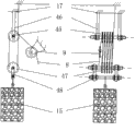
Fig. 1 is the structural map of first embodiment of the utility model.
Fig. 2 is the I-I cut-open view of Fig. 1.
Fig. 3 is the front elevation of Fig. 1 middle rolling car A when on the inverted T-shaped track, having connected connecting link, float.
Fig. 4 is the II--II cut-open view of Fig. 3.
Fig. 5 is the zoomed-in view of driving A on the inverted T-shaped track.
Fig. 6 is the connecting link structural map.
Fig. 7 is the structural map of pulley blocks.
Fig. 8 is the structural map of second embodiment of the utility model.
Fig. 9 is the III-III cut-open view of Fig. 8.
Figure 10 is the front elevation of Fig. 8 middle rolling car B on the umbrella shape track.
Figure 11 is the IV-IV cut-open view of Figure 10.
1. inclined shafts among the figure, 2. inverted T-shaped track, 3. rib, 4. diagonal rib muscle, 5. driving A, 6. connecting link, 7. float, 8. cable wire; 9. angle sheave, 10. driving wheel, 11. chains, 12. water level gauges, 13. platforms, 14. pulley blockss, 15. balance bobs, 16. straight wells; 17. fixture, 18. filter screens, 19. sand basins, 20. water inlet pipes, 21. filter screens, 22. pier bases, 23. instrument rooms, 24. inclined shaft lower floors; 25. the inclined shaft upper strata, 26. bolts, 27. bolts, 28. bolts, 29. guardrails, 30. clamping plate, 31. upper rollers, 32.; 33. nut, 34. base plates, 35. bottom rollers, 36., 37. knots that can be undone by a pull, 38. screw rods, 39. bolts, 40. rank steel; 41. bolt, 42. rank steel, 43. bolts, 44. bolts, 45. fixed pulleys, 46. supports, 47. travelling block, 48. supports; 49. inclined shaft, 50. umbrella shape tracks, 51. driving B, 52. connecting links, 53. floats, 54. inclined shaft lower floors, 55. inclined shaft upper stratas; 56. bolt, 57. bolts, 58. guardrails, 59. clamping plate, 60.V type sheave, 61.; 62. nut, 63. split pins, 64. rollers, 65., 66. bolts, 67. rank steel
Embodiment
The oblique shape of the utility model is laid a pipeline and is constituted inclined shaft, and the xsect of well body can be circular, oval, square, many rhombus, also can be their array configuration.The interior cross-sectional area of well body is got greatly as far as possible, and enough space mounting floats arranged, when making float float in the water and the minimum distance of inclined shaft inwall be not less than 75mm.Inclined shaft is upper and lower two-layer unitized construction, and material can be the reinforced concrete moulding by casting, also can process with sheet steel.The stereoscopic situation of well can be laid on littoral slope, builds the reinforced concrete knoll in case of necessity and supports.When lower floor's well body was the formed by integrally casting reinforced concrete moulding, dual-side was along pre-embedded bolt, and bottom interior wall polishes smooth as far as possible.Also should make inwall smooth as far as possible when making with sheet steel.The upper strata is a watt shape, is made up of the prefabricated component that polylith is movable, and reinforced concrete structure or sheet steel manufacturing all can.Connect with bolt between the levels.The slit is eliminated by the interface portion that combines between the higher and lower levels between the prefabricated component of upper strata.The material of rigid track can be used metal material in the well body, also can use nonmetallic materials; Can use solid material, also can use core material, but should select physical strength high, pliability is good; Water-fast, wear-resisting, corrosion-resistant, hot coefficient of dilatation is little, and is anti-aging, light weight; Economy obtains easily, and material processed considers that as far as possible selection on the market can available section bar easily.The exercise group part is formed in float, connecting link, driving jointly, selects economy, durable material respectively for use.Movable and fixed pulley in the pulley assembly is made with hard plastics sheet material or light aluminum alloy sheet material edge ball bearing.Balance bob is processed the concrete counterweight with reinforced concrete, can be made into polylith, makes things convenient for counterweight, and shape of cross section can be circular, square or polygon, matches with straight well shape of cross section in the instrument room.Straight well can be poured into a mould with reinforced concrete in the instrument room, and is also available brick, and also available tubing edge is built, and it is principle that the size of straight well cross-sectional area is not collided the borehole wall up and down with travelling block, support, the balance bob that satisfies pulley blocks.The group number of moving fixed pulley group is relevant in the gradient of the range of stage of the degree of depth of straight well and survey water body, inclined shaft design, the pulley blocks, and after the inclined shaft gradient was set, the degree of depth of straight well was directly proportional with range of stage, is inversely proportional to the group number of pulley blocks.The degree of depth of straight well should satisfy the requirement of the water body range of stage of surveying.Angle sheave is the metal balls bearing arrangement, driving wheel edge axle, and axle two ends cover ball bearing also is fixed in the bearing seat.Cable wire adopts the bloated little stainless steel wire rope of coefficient of hot line.
In the embodiment shown in fig. 1, inclined shaft (1): be ellipse, get minor axis greater than more than the 800mm.Be upper and lower double-layer structure, pour into a mould with reinforced concrete.The smooth bottom of inclined shaft lower floor (24), dual-side is along each pre-buried two row bolt, and wherein inboard bolt (26) is used to install rib (3) and diagonal rib muscle (4); Outside bolt (27) is used to install inclined shaft upper strata (25).Inclined shaft upper strata (25) is thin than inclined shaft lower floor (24), gets 1/3~1/2 of inclined shaft lower floor (24) thickness.The length of the every block of prefabricated component in inclined shaft upper strata (25) is advisable about with 1.0m, convenient carrying and mounting or dismounting.
The physical strength of inclined shaft (1) will reach the requirement of industry standard and standard.
Rib (3), diagonal rib muscle (4): make with corrosion resistant metal material, add square tube or pipe produced with combination like the band steel of stainless steel material, physical strength is big, lighter weight.Rib (3), diagonal rib muscle (4), bolt (26), (28) are laid along the well body and are wanted evenly, have enough load-bearing capacitys to guarantee that inverted T-shaped track (2) is firm.Mounted rib (3), diagonal rib muscle (4) can not brush up against the inwall of inclined shaft upper strata (25).
Inverted T-shaped track (2): adopt the processing of stainless steel square pipe profile, can find the section bar of same shape best, end face soldering stainless steel bolt (28).
When bolt (28) just has been fixed on the below of rib (3), diagonal rib muscle (4) with inverted T-shaped track (2) after rib (3), diagonal rib muscle (4) are connected.
One face down bonding of inverted T-shaped track (2) connects guardrail (29).Guardrail (29) is made up of stud and diagonal bar; With the stainless reinforcing bar welding about diameter 3.0mm; Stud is evenly laid about 0.5m at interval perpendicular to inverted T-shaped track (2) and the lateral surface that carries over track, and its effect is to make cable wire (8) all the time in the constant inclined surface of inverted T-shaped track (2).Stud leans nearly track one side, and to be parallel to reinforcing bar of inverted T-shaped track (2) welding be exactly diagonal bar.The opposite side of inverted T-shaped track (2) does not weld guardrail, and is shown in Figure 2.
Driving A (5): by clamping plate (30), upper roller (31), axle (32), nut (33), base plate (34), bottom roller (35), axle (36), knot that can be undone by a pull (37), screw rod (38), bolt (39), rank steel (40), bolt (41), rank steel (42), bolt (43) is formed.
Its middle clamp plate (30), base plate (34) are concave shape with stainless sheet steel processing with the fixing back of bolt (39) cross sectional shape.Clamping plate (30) interior plate face boring makes things convenient for nut (33) that axle (32) is fixing, also is convenient to bolt (41), bolt (43) and will hold in the mouth steel (40) respectively, hold in the mouth steel (42) and be connected with the interior plate face.Rank steel (40), rank steel (42) can not contact with inverted T-shaped track (2), can not collide with guardrail (29), and rank steel (40), rank steel (42) and inverted T-shaped track (2) get on the right track and will leave the spacing about 2mm between the face.The effect of rank steel (40) is the retentate of removing on the track; Rank steel (42) is used for fixing a termination of cable wire (8).Only with on one side, another side is empty.
The boring of clamping plate (30) outer panel face, through bolt (39) that base plate (34) and clamping plate (30) is fixing, through bolt (44) clamping plate (30) lateral surface is connected with connecting link (6) medial surface.Base plate (34) is gone out mounting hole, reserves the space of installation for roller (35); The loose joint termination that mounting hole one side is riveted over knot that can be undone by a pull (37); Opposite side boring is also opened thread; With screw rod (38) knot that can be undone by a pull (37) other end is fixed on base plate (34) below; The bottom surface of knot that can be undone by a pull (37) and base plate (34) is fixed on axle (36) bottom of base plate (34) jointly, so just bottom roller (35) has been fixed.
Spacing between a pair of axle (32) two ends on the same axis is greater than the thickness 2~3mm of the middle upright beam of inverted T-shaped track (2), guarantees that driving A (5) can go up even running at inverted T-shaped track (2).See Fig. 4.
Upper roller (31), bottom roller (35) are ball bearing structure.
Bolt (41), (43), axle (32), (36), nut (33), knot that can be undone by a pull (37), screw rod (38) are all selected the stainless steel material manufacturing for use.
Connecting link (6): shown in Figure 6, the stainless steel material manufacturing.Shape is the Y type, and following joint is vertical rod, is I shape, is connected to float (7) center upper portion bottom, and last joint is the U type, and clamping plate (30) outside with driving A (5) connecting link (6) U type is inboard with bolt (44) is fixing.Driving A (5) every limit clamping plate (30) have 2 bolts (44), the oblique angle of locking driving A (5).
Float (7): make with engineering plastics or stainless sheet steel, the middle part is a right cylinder, the bottom Rotary-table, and bottommost is spheroidal, the little turtleback shape that is in top, center upper portion is the lower end of extension bar (6) in succession.Present embodiment is got cylinder diameter more than or equal to 400mm.
When being placed in the water separately after float (7) counterweight, water surface curve floods to the right cylinder upper edge.When all objects install, connect cable wire (8), hang up the counterweight of balance bob (15) and adjustment balance bob (14), the water surface is flooded to the cylindrical centre of float (7), this moment, the vertical water surface was wanted in the vertical rod of connecting link (6) I shape part.
Cable wire (8): select stainless steel wire rope (1Cr18Ni9Ti) for use, diameter of phi 1.0 ± 0.04mm, 19 of sub-threads.
Angle sheave (9): guiding cable wire (8) operation pulley, ball bearing structure.
Driving wheel (10): be the output block of water level information, driving wheel edge axle, axle two ends cover ball bearing also is fixed in the bearing seat.Can make chain drive as required, a kind of form in sheave, gear, the axle coupling etc. is transmitted water level information to water level gauge.
Chain (11): with driving wheel and water level gauge coupling.Can select chain, belt, need not during with gear, axle connection.
Water level gauge (12): can select the wheel of arbitrary form, the water level instrument that axle rotates coupling for use.
Platform (13): the platform that reinforced concrete or iron plate are done, enough physical strengths arranged, can long-time bearing the stable operation of this water level platform, and make things convenient for the installation and the operation of instrument and equipment.
Pulley blocks (14): ball bearing pulley.Be made up of coaxial 5 fixed pulleys (45) and 5 travelling block (47) and fixed pulley support (46), moving pulley bracket (47), its stroke should satisfy omnidistance range of stage requirement.Here, the stroke of pulley blocks (14) is that cable wire (8) is at 1/10 of rail stroke.The group number of fixed pulley (45) and 5 travelling block (47) can select the pool flexibly according to actual conditions.
Balance bob (15): balance bob is processed the concrete counterweight with reinforced concrete; Process the polylith thin slice, make things convenient for counterweight, shape of cross section can be circular, square or polygon; Match with the straight well shape of cross section in the instrument room, carry out counterweight according to the situation of float (7).
Straight well (16): but the hand excavation, lay bricks stone or deposit concrete construction etc., it is the passage of travelling block (47) and balance bob (15) operation.The visual concrete condition of construction form of xsect is selected.
Filter screen (18), (21): nylon mesh, effect are to prevent that big floating thing, aquatic animal from getting in water inlet pipe (20), sand basin (19) and the inclined shaft (1).
Sand basin (19): the pond of filtering water body sedimentation silt.Can select rectangle, it is circular also can selecting, available reinforced concrete cast, and materials such as also available brick, stone are built by laying bricks or stones.Chi Shen is advisable to be no more than 2m, and Chi Ding adds movable lid sealing, and existing certain degree of depth stores silt, is convenient to the removing of mud again.Rocky water body can be built multistage sand basin.The sand basin of building (19) should meet the requirement of relevant technologies standard or standard.
Water inlet pipe (20): play the direct water effect.The optional circle of horizontal water inlet pipe xsect or square.Cross-sectional area should meet the requirement of relevant technologies standard or standard.Can adopt materials such as steel pipe, concrete pipe, engineering plastics pipe, also available brick, barnacle become forms such as closed conduit.When water inlet pipe (20) is long, sectional construction multi-section water-inlet pipe (20) and multistage sand basin (19).
Pier base (22): block of wood of reinforced concrete cast, the littoral slope of inclined shaft (1) is laid when physical features is difficult to support and is built.
Instrument room (23): driving wheel (10) can be installed, lay water level gauge (12), satisfy the staff and conveniently instrument and equipment is carried out operation and maintenance, satisfy the house of demand of technical standard.It is then better that condition when permission is installed to office with instrument.
Comparison embodiment illustrated in fig. 8 and embodiment illustrated in fig. 1; Because of rigid track form difference; The position of laying has different, caused the structure of inclined shaft, driving, and the connected mode of float and connecting link has difference; Inclined shaft embodiment illustrated in fig. 1 (1) mouth is outside the instrument room, and inclined shaft embodiment illustrated in fig. 8 (49) mouth then directly leads in the instrument room.In addition each member all is the same.So to embodiment illustrated in fig. 8 narration and discrepant part embodiment illustrated in fig. 1, identical part is no longer told about.
In the embodiment shown in fig. 8, inclined shaft (49): be ellipse, get minor axis greater than more than the 800mm.The levels structure is poured into a mould with reinforced concrete.Inclined shaft lower floor (54) is pre-buried two row bolts along the bottom, are used to install umbrella shape track (50).Each pre-buried row bolt (56) of dual-side is used to install inclined shaft upper strata (55).Inclined shaft upper strata (55) is thin than inclined shaft lower floor (54), gets 1/3~1/2 of inclined shaft lower floor (54) thickness.
The physical strength of inclined shaft (49) will reach industry standard and standard-required.
Umbrella shape track (50): adopt physical strength high, pliability is good, and is water-fast, wear-resisting, corrosion-resistant, and hot coefficient of dilatation and reinforced concrete are approaching, and economy obtains easily, and the metal of processing or nonmetallic materials are made easily.Solid material can be used, also hollow material can be adopted.The wide about 10mm of horizontal rail level on the umbrella avris.
Use with umbrella shape track (50) homogeneity, diameter 5mm about wire rod, make guardrail (58) with the method for making guardrail embodiment illustrated in fig. 1 (29), and with its welding or paste on the lateral surface of umbrella shape track (50).See shown in Figure 9.
Driving B (51): by clamping plate (59), V-type sheave (60), axle (61), nut (62), split pin (63), roller (64), axle (65), bolt (66), rank steel (67) is formed.
Because of driving B (51) moves in water, V-type sheave (60) wherein, roller (64) all adopt engineering plastics to make.Other parts are made with stainless steel material.To hold in the mouth steel (67) with bolt (66) and be fixed on the clamping plate (59), rank steel (67) end, leave the right or normal track about face 2mm, can not run into guardrail (58).See shown in Figure 11.
Connecting link (52): material, structure are just turned usefulness around with embodiment illustrated in fig. 1 identical, promptly are the shape of falling Y, and it is inverted U-shaped that the lower end is, and its medial surface is connected with clamping plate (59) lateral surface of driving B (51); The upper end is I shape, and the top is connected with the bottom central of float (53).
Float (53): material, structure be with embodiment illustrated in fig. 1 identical, and just the position and the mode of itself and connecting link (52) are different.Also use material to make as plastics or stainless sheet steel, the middle part is a right cylinder, the bottom Rotary-table, and bottommost is spheroidal, the little turtleback shape that is in top.The central authorities of bottommost spheroidal are the rod end of extension bar (52) in succession.
When all objects install, connect cable wire (8), hang up the counterweight of balance bob (15) and adjustment balance bob (15), the water surface is flooded to the cylindrical centre of float (53), this moment, the vertical water surface was wanted in the vertical rod of connecting link (52) I shape part.
Miscellaneous part is with embodiment illustrated in fig. 1 identical.
Narrate the principle that the utility model is realized the water-level observation robotization with first embodiment shown in Figure 1 below:
When the natural water water level rose, the interior water body water level of inclined shaft (1) also rose, and float (7) buoyancy increases, and float (7) moves upward and promotes driving A (5) operation through connecting link (6); Because the orientation of inverted T-shaped track (2); Limit driving (5) upwards operation, cause float (7) also can only move upward, simultaneously with this along the distinctive gradient of inverted T-shaped track (2) along inverted T-shaped track (2) inclined-plane; Cable wire (8) is lax; But under pulley blocks (14) and balance bob (15) combination action of gravity, again cable wire (8) has been tightened up, thereby promoted driving wheel (10) running, driven water level gauge (12) record water level.Float (7) was in static relatively state when the dynamic stress that makes up both when float (7) and pulley blocks (14) and balance bob (15) reached balance; Driving A (5) has stopped the operation that making progress; Driving wheel (10) also stops to the direction running of rising; Water level reaches peak value, and water level gauge (12) records relative peak level.
When the natural water decline of water table; The interior water body water level of inclined shaft (1) also descends; Float (7) loses part buoyancy, and float (7) moves downward after overcoming pulley blocks (14) and balance bob (15) combination broach under the effect of self gravitation, again because the orientation of inverted T-shaped track (2); Limiting driving A (5) moves downwards along inverted T-shaped track (2) inclined-plane; Thereby force float (7) to move downward, thereby pull line (8) promotes driving wheel (10) running, drive water level gauge (12) record water level along the distinctive gradient of inverted T-shaped track (2).Float (7) was in static relatively state when the dynamic stress that makes up both when float (7) and pulley blocks (14) and balance bob (15) reached balance; Driving A (5) has stopped downward operation; Driving wheel (10) also stops the direction running to water-break; Water level arrives the lowest point, and water level gauge (12) records relative lowest water level.
Go round and begin again, move in circles, realize the overall process of record water body SEA LEVEL VARIATION automatically.
The item that should be noted that is:
1, rigid track is the vitals of the utility model, requires whole piece track high conformity, and is neatly well-balanced, keeps straight, and rigid track both sides inclined shaft is wanted symmetry after installing, and guarantees that rigid track is positioned at the vertical centering control top-stitching of inclined shaft.
2, after all parts installed, float (7), (53) should be able to float on the interior water surface of inclined shaft, and the water surface floods to float (7), (53) cylindrical centre.The vertical rod of connecting link (6), (52) should be perpendicular to the water surface.
3, the wheel shaft (32) among Fig. 1 embodiment, the wheel shaft (65) among Fig. 8 embodiment are that coaxial cable uses in pairs; Two axle low coverage shaft pertainings to the big 2~3mm of the vertical vertical beam thickness of its corresponding rigid track of gap ratio; And 4 roller shafts (32) of each limit clamping plate, (65) termination height unanimity in driving (5), (51); A pair of roller shaft only allows the termination contact track vertical beam wall of an axle when guaranteeing the driving operation, reduces frictional resistance.The amplitude of teeter in the time of can limiting simultaneously the driving operation guarantees the driving even running.
4, among Fig. 1 embodiment among 2 rollers (31) of II--II cut-open view (Fig. 4) and 2 rollers (35), Fig. 8 embodiment 1 V-type sheave (60) of IV-IV cut-open view (Figure 11) and 2 rollers (64) be called one group of wheel; Driving A (5) and driving B (51) have installed 4 groups of wheels, and benefit is that the driving operation is unaffected when micro-cracks appears in track.When rigid track is intact when straight, driving A (5) and driving B (51) can only use 2 groups of wheels to get final product, and have both reduced the frictional resistance of driving a vehicle, and have reduced cost again.
5, after all parts install, check the mated condition of each parts, then total system is debugged, guarantee system's operate as normal.Inclined shaft upper strata (25), (55) are installed at last.
6, inclined shaft (1), (49), the well head of straight well (16) must be installed the doorway and protect.
7, biological parasitic for preventing, inclined shaft (1), (49) inwall adopt special plastic coating, prevent that the shellfish aquatic animal from adhering to parasitism, prevent that hydrophyte from adhering to spread.Inverted T-shaped track (2), umbrella shape track (50) coating butter and special pesticide prevent that aquatic animals and plants from adhering to.
8, for guaranteed water level director phase stable operation, need make regular check on, safeguard.
The structural form of two embodiment of cumulated volume utility model learns that this inclined shaft water level platform has following distinguishing feature:
1, inclined shaft is littoral the laying, does not have work high above the ground, and the basis requires low, and construction costs is low, good economy performance.
2, the gradient of inclined shaft can be selected comparatively ideal design load in certain limit as the case may be.
3, inclined shaft is 2 layers up and down, and the upper strata is a watt shape structure, and easy accessibility is safeguarded simple.
4, float is the power of this inclined shaft water level platform operation with the buoyancy change that SEA LEVEL VARIATION produces.Here adopt the bigger float of diameter, the buoyancy change rate is big, the power foot.
5, the suffered resistance of this water level platform system mainly be driving at the resistance and the force of sliding friction of cable wire on orbital plane of orbital motion, the driving running resistance mainly be between roller and the rail level force of rolling friction and roller and spool friction force.First embodiment (shown in Figure 1) roller adopts ball bearing structure, and driving runs on more than the water surface, and volume own is less, and roller is littler, and resistance coefficient is little, so suffered resistance is very little.Second embodiment (shown in Figure 8) roller adopts entity roller bearing structure, and driving runs under water, and resistance coefficient is slightly larger, but because the driving volume is little, roller is very little, so suffered resistance is also very little.The quality of the force of sliding friction invar rope of cable wire and track is less, and the friction factor of cable wire and rail level is also less, so sliding-frictional resistance is also little.So, can guarantee that this water level platform water level induction, transmission under various gradients and range of stage condition all have higher sensitivity.
6, driving side cable wire is layered on the orbital plane along track in the inclined shaft.Rigid track is the orbit of driving, also is the track of rope slip simultaneously.Cable wire slides on straight orbital plane; When having eliminated straight long cable wire and existing horizontal range unsettled because of sole mass produces the water level error of measurement that sag causes, thereby guaranteed that this water level platform water level under various gradients and range of stage condition transmits degree of accuracy is preferably all arranged.
7, in the instrument room, build straight well, use pulley blocks and balance bob to form the cable wire displacement controller, use just that cable wire is collected and broadcasted to pulley blocks, balance bob makes system keep equilibrium state, with the displacement restriction of cable wire in the scope of setting.Like this, the stroke of balance bob side cable wire is compared with the stroke of driving side cable wire and is significantly reduced.Example: certain natural water range of stage 20m; 30 ° of gradients of design, but knowing and doing car side cable wire range be from lowest water level to the peak level position, be 40m; Get that pulley blocks is fixed, the group number of travelling block is 5 groups; So, be fixed, the movable spacing range of travelling block with the corresponding balance bob side cable wire stroke of driving side cable wire stroke, be 4m.Suppose the high 3.5m of instrument room's terrace; Decide travelling block diameter 200mm, balance bob accounts for high 0.5m, when water level is minimum; Fixed, moving sliding spacing is the shortest; Be definite value: supposition is fixed at this moment, the travelling block wheelbase is 250mm, is installed in the place of instrument room's terrace, and balance bob bottom surface and terrace distance is controlled in the 1m.When water level was the highest, the balance bob bottom surface just can meet the demands as long as on ground below instrument room's inner equilibrium hammer, build the straight well of the above degree of depth of 1.5m apart from terrace 5m.If increase fixed, running block number, the straight well degree of depth can also reduce, and does not even build straight well.
8, using pulley blocks collects and broadcasts cable wire and eliminated the water level error (erect type well logging water level platform rises or the about half that drops to gamut can produce this error at water level) that goes out, goes into water generates because of balance bob.
9, in the driving rank steel is installed.The rank steel is the parts of fixing tightwire termination, also is the parts of removing the retentate on the rigid track, makes driving have certain block removing function, has improved the reliability of water level platform system.
Claims (4)
1. floater type inclined well water position observation platform; Be called for short inclined shaft water level platform; It is characterized in that: on natural water bank slopes such as river, river, lake, storehouse, sea, lay a tilting pipeline and constitute inclined shaft; Lay a rigid track in the inclined shaft, driving is installed on the rigid track, driving links to each other with float through connecting link; Driving is simultaneously also joined with a termination of a cable wire; This cable wire is along rigid track, be connected on the fulcrum in the instrument room on the bank through another termination behind the angle sheave, driving wheel, pulley assembly, and a balance bob hangs on the support below of pulley blocks travelling block, has been made up of induction, the transmission system of natural water SEA LEVEL VARIATION jointly float, connecting link, driving, cable wire, angle sheave, driving wheel, pulley blocks, balance bob.
2. according to claim 1 inclined shaft water level platform, it is characterized in that: inclined shaft is 2 layers of unitized construction up and down, and the upper strata is a watt shape.
3. according to claim 1 inclined shaft water level platform, it is characterized in that: driving side cable wire is layered on the orbital plane along track in the inclined shaft.
4. according to claim 1 inclined shaft water level platform, it is characterized in that: in the instrument room, build straight well, use pulley blocks and balance bob to form the cable wire displacement controller.
Priority Applications (1)
| Application Number | Priority Date | Filing Date | Title |
|---|---|---|---|
| CN2012201588568U CN202494491U (en) | 2012-04-03 | 2012-04-03 | Float type inclined shaft water level observation platform |
Applications Claiming Priority (1)
| Application Number | Priority Date | Filing Date | Title |
|---|---|---|---|
| CN2012201588568U CN202494491U (en) | 2012-04-03 | 2012-04-03 | Float type inclined shaft water level observation platform |
Publications (1)
| Publication Number | Publication Date |
|---|---|
| CN202494491U true CN202494491U (en) | 2012-10-17 |
Family
ID=47000716
Family Applications (1)
| Application Number | Title | Priority Date | Filing Date |
|---|---|---|---|
| CN2012201588568U Expired - Fee Related CN202494491U (en) | 2012-04-03 | 2012-04-03 | Float type inclined shaft water level observation platform |
Country Status (1)
| Country | Link |
|---|---|
| CN (1) | CN202494491U (en) |
Cited By (4)
| Publication number | Priority date | Publication date | Assignee | Title |
|---|---|---|---|---|
| CN103185626A (en) * | 2013-03-11 | 2013-07-03 | 合肥工业大学 | Reservoir level tester for pumped storage power plant and installation method of reservoir level tester |
| CN103552902A (en) * | 2013-11-02 | 2014-02-05 | 广东安元矿业技术服务有限公司 | Energy-saving double-hook inclined shaft hoisting method for mine |
| CN109342674A (en) * | 2018-08-31 | 2019-02-15 | 河海大学 | Lake water quality online monitoring and analysis system |
| CN117309102A (en) * | 2022-06-23 | 2023-12-29 | 厦门瀛寰海洋仪器有限公司 | Water level and water surface fluctuation monitoring device based on cable-stayed installation mode |
-
2012
- 2012-04-03 CN CN2012201588568U patent/CN202494491U/en not_active Expired - Fee Related
Cited By (6)
| Publication number | Priority date | Publication date | Assignee | Title |
|---|---|---|---|---|
| CN103185626A (en) * | 2013-03-11 | 2013-07-03 | 合肥工业大学 | Reservoir level tester for pumped storage power plant and installation method of reservoir level tester |
| CN103185626B (en) * | 2013-03-11 | 2015-04-22 | 合肥工业大学 | Reservoir level tester for pumped storage power plant and installation method of reservoir level tester |
| CN103552902A (en) * | 2013-11-02 | 2014-02-05 | 广东安元矿业技术服务有限公司 | Energy-saving double-hook inclined shaft hoisting method for mine |
| CN109342674A (en) * | 2018-08-31 | 2019-02-15 | 河海大学 | Lake water quality online monitoring and analysis system |
| CN109342674B (en) * | 2018-08-31 | 2021-07-27 | 河海大学 | Lake water quality online monitoring and analysis system |
| CN117309102A (en) * | 2022-06-23 | 2023-12-29 | 厦门瀛寰海洋仪器有限公司 | Water level and water surface fluctuation monitoring device based on cable-stayed installation mode |
Similar Documents
| Publication | Publication Date | Title |
|---|---|---|
| CN202494491U (en) | Float type inclined shaft water level observation platform | |
| CN101078211A (en) | Underwater anchorage system auxiliary wooden stool structure platform and construction method thereof | |
| CN102535529A (en) | Construction method of self-balancing method pile foundation bearing capacity test device | |
| EA014336B1 (en) | Fixed structure platform on water | |
| CN110656890B (en) | Deepwater geological drilling casing, casing hoisting system and casing hoisting method | |
| CN1472400A (en) | Pre-tensioning positioning of anchor pier with steel hanging box as a whole floating anchor pier, double as drilling platform scheme | |
| CN101813508A (en) | Floater type inclined tube (wall) water level observation platform | |
| CN202066560U (en) | Float type water level observation platform | |
| CN105178347B (en) | A kind of offshore anemometer tower foundation, marine survey wind platform and its application method | |
| CN1861982B (en) | Gravity cable winding float-type water gage | |
| CN211773879U (en) | Anti-floating pipe gallery with adjustable balance weight | |
| CN114202894A (en) | Multi-target joint monitoring and early warning device for bridge pier, method and pile foundation | |
| CN206117567U (en) | Floating photovoltaic anchor on water suitable for high water level is poor | |
| CN207580112U (en) | Tension leg type high stability point type floats platform | |
| CN212605667U (en) | Self-balancing floating hydrological monitoring device | |
| CN207063007U (en) | A kind of walling crib ruggedized construction | |
| CN201288324Y (en) | Wooden stool platform structure for deep water foundation construction | |
| CN103352598A (en) | Positioning tower used for mounting multilayer cubic blocks in deep water | |
| CN201672958U (en) | Float type float ball inclined tube water level platform | |
| CN212452649U (en) | Basalt stratum underwater concrete pouring system | |
| CN211478364U (en) | Flow measuring device for hydraulic engineering | |
| CN210507175U (en) | Support template device for reinforcing bridge | |
| CN202492846U (en) | Drop hammer pile-sinking device | |
| CN201981808U (en) | Deep-water floating type safety swimming pool | |
| RU189266U1 (en) | INTERMEDIATE PUMP AND TUMPER SUPPORT OF UNDERWATER AUTOMOBILE TRAIL BRIDGE (PARM) |
Legal Events
| Date | Code | Title | Description |
|---|---|---|---|
| C14 | Grant of patent or utility model | ||
| GR01 | Patent grant | ||
| C17 | Cessation of patent right | ||
| CF01 | Termination of patent right due to non-payment of annual fee |
Granted publication date: 20121017 Termination date: 20140403 |