CN202493395U - Potential-utilization-type free-piston organic-rankine-cycle natural gas compressor - Google Patents
Potential-utilization-type free-piston organic-rankine-cycle natural gas compressor Download PDFInfo
- Publication number
- CN202493395U CN202493395U CN2012200055231U CN201220005523U CN202493395U CN 202493395 U CN202493395 U CN 202493395U CN 2012200055231 U CN2012200055231 U CN 2012200055231U CN 201220005523 U CN201220005523 U CN 201220005523U CN 202493395 U CN202493395 U CN 202493395U
- Authority
- CN
- China
- Prior art keywords
- working
- valve
- cylinder
- working medium
- compression
- Prior art date
- Legal status (The legal status is an assumption and is not a legal conclusion. Google has not performed a legal analysis and makes no representation as to the accuracy of the status listed.)
- Expired - Fee Related
Links
- VNWKTOKETHGBQD-UHFFFAOYSA-N methane Chemical compound C VNWKTOKETHGBQD-UHFFFAOYSA-N 0.000 title claims abstract description 198
- 239000003345 natural gas Substances 0.000 title claims abstract description 99
- 230000006835 compression Effects 0.000 claims abstract description 101
- 238000007906 compression Methods 0.000 claims abstract description 101
- 239000012530 fluid Substances 0.000 claims abstract description 99
- 239000007788 liquid Substances 0.000 claims abstract description 37
- 238000010438 heat treatment Methods 0.000 claims description 39
- 239000007789 gas Substances 0.000 claims description 9
- 238000007789 sealing Methods 0.000 claims 2
- 238000000926 separation method Methods 0.000 claims 1
- 238000009834 vaporization Methods 0.000 abstract description 9
- 230000008016 vaporization Effects 0.000 abstract description 9
- 238000002156 mixing Methods 0.000 abstract description 2
- 239000002918 waste heat Substances 0.000 abstract description 2
- 238000000034 method Methods 0.000 description 15
- 239000000446 fuel Substances 0.000 description 5
- 238000002485 combustion reaction Methods 0.000 description 3
- 238000009835 boiling Methods 0.000 description 2
- 238000005265 energy consumption Methods 0.000 description 2
- 101000623895 Bos taurus Mucin-15 Proteins 0.000 description 1
- 238000009833 condensation Methods 0.000 description 1
- 230000005494 condensation Effects 0.000 description 1
- 238000001816 cooling Methods 0.000 description 1
- 230000007423 decrease Effects 0.000 description 1
- 238000010586 diagram Methods 0.000 description 1
- 238000004134 energy conservation Methods 0.000 description 1
- 239000003208 petroleum Substances 0.000 description 1
- 239000007921 spray Substances 0.000 description 1
- 238000005507 spraying Methods 0.000 description 1
- 239000000126 substance Substances 0.000 description 1
- 239000013589 supplement Substances 0.000 description 1
Images
Landscapes
- Engine Equipment That Uses Special Cycles (AREA)
Abstract
潜能利用式自由活塞有机郎肯循环天然气压缩装置属有机朗肯循环热能利用技术领域,本实用新型中动力活塞在工作缸内作线性往复运动,通过连杆带动压缩活塞压缩低压天然气,形成高压天然气;同时向完成做功循环的汽态工质中喷入低温液态工质,使做功后的工质放热成为液态,低温液态工质吸收做功后工质的热量,温度升高,成为不饱和工质;本实用新型通过改变动力活塞与压缩活塞的面积比,实现改变压缩天然气的压缩比;通过控制单元控制比例阀的开度,可以改变低温工质与高温工质在工质混合器中的混合比例;本实用新型可充分利用做功后工质的余热和工质的汽化潜热,提高有机朗肯循环的热效率,实现节约能源和保护环境的目的。
The potential utilization type free piston organic Rankine cycle natural gas compression device belongs to the technical field of organic Rankine cycle heat energy utilization. In the utility model, the power piston performs linear reciprocating motion in the working cylinder, and the compression piston is driven by the connecting rod to compress low-pressure natural gas to form high-pressure natural gas. ; At the same time, inject low-temperature liquid working medium into the gaseous working medium that has completed the work cycle, so that the working medium after doing work will release heat and become liquid. quality; the utility model realizes changing the compression ratio of compressed natural gas by changing the area ratio of the power piston and the compression piston; by controlling the opening degree of the proportional valve through the control unit, the ratio of the low-temperature working medium and the high-temperature working medium in the working medium mixer can be changed. Mixing ratio; the utility model can make full use of the waste heat of the working fluid and the latent heat of vaporization of the working fluid, improve the thermal efficiency of the organic Rankine cycle, and realize the purpose of saving energy and protecting the environment.
Description
技术领域 technical field
本实用新型属有机朗肯循环热能利用技术领域,具体涉及一种潜能利用式自由活塞有机郎肯循环天然气压缩装置。The utility model belongs to the technical field of organic Rankine cycle heat energy utilization, in particular to a potential utilization type free piston organic Rankine cycle natural gas compression device.
背景技术 Background technique
随着世界经济飞速发展,能源消耗量急剧增加,节能已成为各国普遍关注的焦点。由于石油具有不可再生的特性,因此节约能源,减少能源消耗,成为各国争相研究的课题。With the rapid development of the world economy and the sharp increase in energy consumption, energy conservation has become the focus of widespread attention in all countries. Due to the non-renewable nature of petroleum, saving energy and reducing energy consumption has become a subject of research by various countries.
由于传统有机朗肯循环中工质的汽化潜热没有被有效利用,工质的汽化潜热完全被浪费了。因此,采用低温热式燃气型天然气压缩机,可以将工质吸收的大部分热量利用并且能利用工质的汽化潜热,提高有机朗肯循环的热效率,同时降低燃料消耗和CO2排放。Since the latent heat of vaporization of the working fluid in the traditional organic Rankine cycle is not effectively utilized, the latent heat of vaporization of the working fluid is completely wasted. Therefore, the use of a low-temperature thermal gas-type natural gas compressor can utilize most of the heat absorbed by the working fluid and the latent heat of vaporization of the working fluid to improve the thermal efficiency of the organic Rankine cycle while reducing fuel consumption and CO2 emissions.
发明内容 Contents of the invention
本实用新型目的是提供一种潜能利用式自由活塞有机郎肯循环天然气压缩装置,该装置以有机朗肯循环为依据,充分利用工质吸收的热量和工质的汽化潜热,将热能转化为机械能,压缩低压天然气,形成所需的高压天然气,实现节约能源的目的。The purpose of the utility model is to provide a potential utilization type free piston organic Rankine cycle natural gas compression device, which is based on the organic Rankine cycle, fully utilizes the heat absorbed by the working medium and the latent heat of vaporization of the working medium, and converts heat energy into mechanical energy , Compress low-pressure natural gas to form the required high-pressure natural gas to achieve the purpose of saving energy.
本实用新型由低压天然气管路进气口1、低压天然气管路2、高压天然气管路出气口3、高压天然气管路4、出气恒压阀I 5、进气单向阀I 6、缸盖组件I 7、压缩缸I 8、压缩活塞I 9、活塞位置传感器I 10、环形连接体I 11、密封垫I 12、弹性限位器I 13、工作缸14、动力活塞15、 连杆16、弹性限位器II 17、密封垫II 18、环形连接体II 19、活塞位置传感器II 20、压缩活塞II 21、压缩缸II 22、缸盖组件II 23、进气单向阀II 24、出气恒压阀II 25、溢流平衡罐26、回流阀27、工质储存罐28、工质泵I 29、电磁阀I 30、工质收集槽I 31、工质泵II 32、电磁阀II 33、电磁阀III 34、冷凝器35、限压阀36、电磁阀IV 37、电磁阀V 38、电磁阀VI 39、工质泵III 40、工质收集槽II 41、定压汽液分离器I 42、工质混合器I 43、比例阀I 44、电磁阀VII 45、电磁阀VIII 46、比例阀II 47、工质混合器II 48、定压汽液分离器II 49、单向阀50、加热锅炉51、控制单元52组成,其特征在于低压天然气管路2上设有低压天然气管路进气口1,低压天然气管路2的两端分别与进气单向阀I 6和进气单向阀II 24连接;高压天然气管路4上设有高压天然气管路出气口3,高压天然气管路4的两端分别与出气恒压阀I 5和出气恒压阀II 25连接;进气单向阀I 6和出气恒压阀I 5都安装在缸盖组件I 7上;进气单向阀II 24和出气恒压阀II 25都安装在缸盖组件II 23上;缸盖组件I 7与压缩缸I 8连接;缸盖组件II 23与压缩缸II 22连接;压缩缸I 8通过环形连接体I 11和密封垫I 12与工作缸14内的工作腔连通;环形连接体I 11与工作缸14之间加装密封垫I 12;压缩缸II 22通过环形连接体II 19和密封垫II 18与工作缸14内的工作腔连通;环形连接体II 19与工作缸14之间加装密封垫II 18;压缩活塞I 9置于压缩缸I 8内部;压缩活塞II 21置于压缩缸II 22内部;压缩活塞I 9与连杆16通过球形铰链连接;压缩活塞II 21与连杆16通过球形铰链连接;动力活塞15与连杆16通过销钉连接;动力活塞15置于工作缸14内部;弹性限位器I 13置于工作缸14内部,弹性限位器I 13的外边缘与工作缸14的外边缘齐平;弹性限位器II 17置于工作缸14内部,弹性限位器II 17外边缘与工作缸14外边缘齐平;活塞位置传感器I 10通过环形连接体I 11和密封垫I 12与工作缸14内部空间连通;活塞位置传感器II 20通过环形连接体II 19和密封垫II 18与工作缸14内部空间连通;低压天然气管路2通过单向阀50与加热锅炉51连接;定压汽液分离器II 49安装在工作缸14的靠近环形连接体I 11的一侧;工作缸14内部靠近环形连接体I 11的工作腔通过定压汽液分离器II 49与加热锅炉51连接;定压汽液分离器I 42安装在工作缸14的靠近环形连接体II 19的一侧;工作缸14内部靠近环形连接体II 19的工作腔通过定压汽液分离器I 42与加热锅炉51连接;工质储存罐28与工质泵I 29连接;工质泵I 29分别与电磁阀I 30、电磁阀IV 37连接;电磁阀I 30、工质收集槽I31、工质泵II 32串联连接;工质泵II 32与比例阀II 47、工质混合器II 48串联连接;工质泵II 32还与电磁阀II 33、加热锅炉51串联连接;工质泵II 32还与电磁阀III 34、冷凝器35串联连接;冷凝器35和限压阀36连接;限压阀36与工质储存罐28连接;限压阀36还与溢流平衡罐26连接;溢流平衡罐26、回流阀27和工质储存罐28串联连接;电磁阀IV 37、工质收集槽II 41、工质泵III 40串联连接;工质泵III 40与比例阀I 44、工质混合器I 43串联连接;工质泵III 40还与电磁阀VI 39、加热锅炉51串联连接;工质泵III 40还与电磁阀V 38、冷凝器35串联连接;加热锅炉51与电磁阀VII 45、工质混合器I 43串联连接;加热锅炉51还与电磁阀VIII 46、工质混合器II 48串联连接;活塞位置传感器I 10和活塞位置传感器II 20采集的信号向控制单元52传输,工质泵I 29、电磁阀I 30、工质泵II 32、电磁阀II 33、电磁阀III 34、电磁阀IV 37、电磁阀V 38、电磁阀VI 39、工质泵III 40、比例阀I 44、电磁阀VII 45、电磁阀VIII 46和比例阀II 47均由控制单元52控制。The utility model is composed of a low-pressure natural gas pipeline inlet 1, a low-pressure natural gas pipeline 2, a high-pressure natural gas
本实用新型的压缩比由下列公式计算:The compression ratio of the present utility model is calculated by following formula:
ε=p2/p0 (1)ε=p 2 /p 0 (1)
A1/A2=α(p2/p1) (2)A 1 /A 2 =α(p 2 /p 1 ) (2)
其中:ε为压缩比,α为大于1.5的常数,p0为压缩缸I(8)或压缩缸II(22)压缩初期的压力,p1为工作缸(14)内部压力,p2为压缩缸I(8)或压缩缸II(22)压缩终了的压力,A1为动力活塞(15)的面积,A2为压缩活塞I(9)或压缩活塞II(21)的面积。Among them: ε is the compression ratio, α is a constant greater than 1.5, p 0 is the initial compression pressure of compression cylinder I (8) or compression cylinder II (22), p 1 is the internal pressure of the working cylinder (14), and p 2 is the compression Cylinder I (8) or compression cylinder II (22) compression end pressure, A 1 is the area of power piston (15), A 2 is the area of compression piston I (9) or compression piston II (21).
本实用新型的原理是:低压天然气管路2向压缩缸I 8提供需要压缩的低压天然气,并向加热锅炉51提供燃烧用天然气。工质泵I 29和工质泵III 40将工质从工质储存罐28中输送到加热锅炉51中,工质吸热后,形成高温高压的过热蒸汽。过热蒸汽通过工质混合器I 43直接喷入工作缸14内部靠近环形连接体II 19一侧的工作腔中,或者与工质收集槽II 41中的工质按一定的比例在工质混合器I 43中混合后喷入靠近环形连接体II 19一侧的工作腔中,工质膨胀做功,推动动力活塞15向另一侧移动。动动力活塞15通过连杆16带动压缩活塞I 9压缩低压天然气,形成高压天然气,输送至高压天然气管路4中。控制单元52通过活塞位置传感器I 10和活塞位置传感器II 20采集的信号,判断动力活塞15在工作缸14内的位置。当动力活塞15移动至控制单元52内部设定的极限位置时,控制单元52根据喷入工作缸14内部靠近环形连接体II 19一侧工作腔内工质的量,判断出工作后工质的所携带的热量,计算将工作缸14内部工作后的工质变成液态所需要喷入的低温液态工质的量。控制单元52控制相应的电磁阀(电磁阀VI 39关闭)开启或者闭合以及比例阀I 44的开度,只向工作缸14内部的靠近环形连接体II 19一侧工作腔喷入经过控制单元52计算的低温工质的量,使做功后的工质降低温度,变成液态;低温工质吸收热量形成不饱和工质,流向工质收集槽II 41,为下一个工作循环提供工作用的工质,减少在加热锅炉51中燃料的消耗量。同时低压天然气管路2向压缩缸II 22提供需要压缩的低压天然气,控制单元52并向加热锅炉51提供燃烧用天然气。工质泵I 29和工质泵II 32将工质从工质储存罐28中输送到加热锅炉51中,工质吸热后,形成高温高压的过热蒸汽。过热蒸汽通过工质混合器II 48直接喷入工作缸14靠近环形连接体I 11一侧的工作腔中,或者与工质收集槽I 31中的工质按一定的比例在工质混合器I 43中混合后喷入工作缸14内靠近环形连接体I 11一侧的工作腔中,工质膨胀作功,推动动力活塞15向另一侧移动,通过连杆16带动压缩活塞II 21压缩低压天然气,形成高压天然气,输送到高压天然气管路4中。The principle of the utility model is: the low-pressure natural gas pipeline 2 provides the low-pressure natural gas that needs to be compressed to the compression cylinder 18, and provides the natural gas for combustion to the heating boiler 51. The working medium pump I 29 and the working medium pump III 40 transport the working medium from the working medium storage tank 28 to the heating boiler 51, and after the working medium absorbs heat, it forms high-temperature and high-pressure superheated steam. The superheated steam is directly sprayed into the working chamber of the working cylinder 14 near the side of the annular connecting body II 19 through the working medium mixer I 43, or is mixed with the working medium in the working medium collection tank II 41 in a certain proportion in the working medium mixer After being mixed in I 43, it is sprayed into the working chamber on one side of the annular connecting body II 19, and the working medium expands to do work, pushing the power piston 15 to move to the other side. Dynamic power piston 15 drives compression piston 19 to compress low-pressure natural gas by connecting rod 16 to form high-pressure natural gas, which is delivered to high-pressure natural gas pipeline 4. The control unit 52 judges the position of the power piston 15 in the working cylinder 14 through the signals collected by the piston position sensor I 10 and the piston position sensor II 20. When the power piston 15 moved to the limit position set inside the control unit 52, the control unit 52 judged the working fluid according to the amount of the working fluid sprayed into the working chamber on the side of the annular connecting body II 19 inside the working cylinder 14. The amount of heat carried is to calculate the amount of low-temperature liquid working medium that needs to be injected to turn the working medium inside the working cylinder 14 into a liquid state. The control unit 52 controls the opening or closing of the corresponding solenoid valve (the solenoid valve VI 39 is closed) and the opening degree of the proportional valve I 44, and only sprays into the working chamber on the side of the annular connecting body II 19 inside the working cylinder 14 through the control unit 52 The amount of the calculated low-temperature working fluid reduces the temperature of the working medium and becomes liquid; the low-temperature working medium absorbs heat to form an unsaturated working medium, which flows to the working medium collection tank II 41 to provide working working fluid for the next working cycle. quality, reducing the consumption of fuel in the heating boiler 51. Simultaneously, the low-pressure natural gas pipeline 2 provides the low-pressure natural gas that needs to be compressed to the compression cylinder II 22, and the control unit 52 also provides the natural gas for combustion to the heating boiler 51. The working medium pump I 29 and the working medium pump II 32 transport the working medium from the working medium storage tank 28 to the heating boiler 51, and after the working medium absorbs heat, it forms high-temperature and high-pressure superheated steam. The superheated steam is directly sprayed into the working chamber of the working cylinder 14 near the side of the annular connecting body I 11 through the working medium mixer II 48, or is mixed with the working medium in the working medium collection tank I 31 in a certain proportion in the working medium mixer I 43 is mixed and sprayed into the working chamber of the working cylinder 14 near the side of the annular connecting body I 11, the working medium expands and does work, pushing the power piston 15 to move to the other side, and the compression piston II 21 is driven by the connecting rod 16 to compress the low pressure Natural gas, forming high-pressure natural gas, is delivered to the high-pressure natural gas pipeline 4 .
本实用新型以有机朗肯循环基本原理为依据,通过改进其基本结构,解决传统朗肯循环过程中工质热量利用率低以及工质的汽化潜热无法利用的难题,能充分利用做功工质的余热和汽化潜热,提高有机朗肯循环的热效率,实现节约能源和保护环境的目的。The utility model is based on the basic principle of the organic Rankine cycle, and by improving its basic structure, it solves the problems of the low heat utilization rate of the working medium and the inability to utilize the latent heat of vaporization of the working medium in the traditional Rankine cycle process, and can make full use of the power of the working medium. Waste heat and latent heat of vaporization can improve the thermal efficiency of the organic Rankine cycle and achieve the purpose of saving energy and protecting the environment.
附图说明 Description of drawings
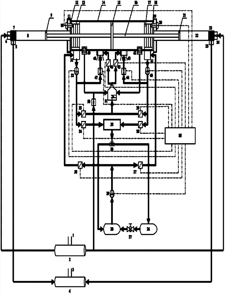
图1为低温热式燃气型天然气压缩机的结构示意图Figure 1 is a schematic diagram of the structure of a low-temperature thermal gas-type natural gas compressor
其中:1.低压天然气管路进气口、2.低压天然气管路、3.高压天然气管路出气口、4.高压天然气管路、5.出气恒压阀I、6.进气单向阀I、7.缸盖组件I、8.压缩缸I、9.压缩活塞I、10.活塞位置传感器I、11.环形连接体I、12.密封垫I、13.弹性限位器I、14.工作缸、15.动力活塞、16.连杆、17.弹性限位器II、18.密封垫II、19.环形连接体II、20.活塞位置传感器II、21.压缩活塞II、22.压缩缸II、23.缸盖组件II、24.进气单向阀II、25.出气恒压阀II、26.溢流平衡罐、27.回流阀、28.工质储存罐、29.工质泵I、30.电磁阀I、31.工质收集槽I、32.工质泵II、33.电磁阀II、34.电磁阀III、35.冷凝器、36.限压阀、37.电磁阀IV、38.电磁阀V、39.电磁阀VI、40.工质泵III、41.工质收集槽II、42.定压汽液分离器I、43.工质混合器I、44.比例阀I、45.电磁阀VII、46.电磁阀VIII、47.比例阀II、48.工质混合器II、49.定压汽液分离器II、50.单向阀、51.加热锅炉、52.控制单元Among them: 1. Low-pressure natural gas pipeline inlet, 2. Low-pressure natural gas pipeline, 3. High-pressure natural gas pipeline gas outlet, 4. High-pressure natural gas pipeline, 5. Gas outlet constant pressure valve I, 6. Intake check valve I, 7. Cylinder head assembly I, 8. Compression cylinder I, 9. Compression piston I, 10. Piston position sensor I, 11. Ring connector I, 12. Gasket I, 13. Elastic limiter I, 14 .Working cylinder, 15. Power piston, 16. Connecting rod, 17. Elastic limiter II, 18. Gasket II, 19. Ring connector II, 20. Piston position sensor II, 21. Compression piston II, 22. Compression cylinder II, 23. Cylinder head assembly II, 24. Intake check valve II, 25. Outlet constant pressure valve II, 26. Overflow balance tank, 27. Return valve, 28. Working medium storage tank, 29. Worker Mass pump I, 30. Solenoid valve I, 31. Working medium collection tank I, 32. Working medium pump II, 33. Solenoid valve II, 34. Solenoid valve III, 35. Condenser, 36. Pressure limiting valve, 37. Solenoid valve IV, 38. Solenoid valve V, 39. Solenoid valve VI, 40. Working medium pump III, 41. Working medium collection tank II, 42. Constant pressure vapor-liquid separator I, 43. Working medium mixer I, 44 .Proportional valve I, 45. Solenoid valve VII, 46. Solenoid valve VIII, 47. Proportional valve II, 48. Working fluid mixer II, 49. Constant pressure vapor-liquid separator II, 50. One-way valve, 51. Heating Boiler, 52. Control unit
具体实施方式 Detailed ways
以下结合附图1对本实用新型技术方案作进一步详细阐述:本实用新型基于有机朗肯循环开发的动力活塞式低温热式天然气压缩机的工作过程可以分为三个阶段:启动阶段、工作阶段、停止阶段。Below in conjunction with accompanying drawing 1, the technical scheme of the utility model is further elaborated: the working process of the utility model based on the organic rankine cycle development of the dynamic piston type low-temperature thermal natural gas compressor can be divided into three stages: start-up stage, working stage, stop phase.
启动阶段:低压天然气从低压天然气管路进气口1进入低压天然气管路2,低压天然气管路2中的低压天然气通过单向阀50向加热锅炉51提供燃烧用燃料;低压天然气管路2中的低压天然气还通过进气单向阀I 6和缸盖组件I 7向压缩缸I 8提供低压天然气;低压天然气管路2中的低压天然气还通过进气单向阀II 24和缸盖组件II 23向压缩缸II 22提供低压天然气。Start-up stage: low-pressure natural gas enters the low-pressure natural gas pipeline 2 from the inlet 1 of the low-pressure natural gas pipeline, and the low-pressure natural gas in the low-pressure natural gas pipeline 2 supplies combustion fuel to the heating boiler 51 through the check valve 50; The low-pressure natural gas also provides low-pressure natural gas to the compression cylinder I 8 through the intake check valve I 6 and the cylinder head assembly I 7; the low-pressure natural gas in the low-pressure natural gas pipeline 2 also passes through the intake check valve II 24 and the cylinder head assembly II 23 provides low-pressure natural gas to the compression cylinder II 22.
控制单元52控制工质泵I 29工作以及电磁阀IV37开启,工质储存罐28中的过冷工质经工质泵I 29、电磁阀IV37进入工质收集槽II 41中,工质收集槽II 41中的工质是过冷工质;此时,控制单元52控制工质泵III 40工作、电磁阀VI 39开启,工质收集槽II 41中的工质经工质泵III 40、电磁阀VI 39进入加热锅炉51,过冷工质在加热锅炉51中吸热后,成为高温、高压的过热蒸汽;控制单元52控制电磁阀VII 45开启以及比例阀I 44的开度;工质收集槽II 41中的工质经工质泵III 40、比例阀I 44进入工质混合器I 43,同时加热锅炉51中高温、高压的过热蒸汽经电磁阀VII 45进入工质混合器I 43,两者在工质混合器I 43中混合后,喷入工作缸14内部靠近环形连接体II 19一侧的工作腔里,高温、高压过热蒸汽在工作腔内部膨胀做功,推动动力活塞15向另一侧移动,动力活塞15通过连杆16带动压缩活塞I 9压缩压缩缸I 8中的低压天然气,形成高压天然气,经缸盖出口组件I 7和出气恒压阀I 5进入高压天然气管路4,通过高压天然气管路出气口3进入天然气压缩罐;同时低压天然气管路2中的低压天然气经进气单向阀II 24和缸盖组件II 23进入压缩缸II 22。控制单元52根据活塞位置传感器I 10和活塞位置传感器II 20采集的信号,判断动力活塞15在工作缸14内部的位置,当动力活塞15运行至控制单元52内部设定的极限位置时,控制单元52控制电磁阀VI39关闭以及比例阀I 44的开度,此时只向工作缸14内部靠近环形连接体II 19一侧的工作腔里喷入过冷的工质,由于做功后的工质温度高于喷入工作腔内的过冷工质的温度,因此做功后的工质放热,温度降低,成为液态;喷入工作腔内的过冷工质吸热后成为不饱和工质,这样就可以利用工质的汽化潜热给过冷工质加热,减少下一个工作循环过程中在加热锅炉51中加热工质所用的天然气燃料的消耗量。工作缸14内部靠近环形连接体II 19一侧工作腔内的工质由于变成液态,压力降低,减少了下一个工作循环动力活塞15向该侧移动时的阻力。工作缸14内部靠近环形连接体II 19一侧工作腔内的液态工质通过定压汽液分离器I 42流入工质收集槽II 41中,当工作缸14内部靠近环形连接体II 19一侧工作腔内的汽态工质变成液态工质时,控制单元52控制比例阀I 44关闭,工质泵III 40停止工作。同时,控制单元52控制电磁阀VI 37关闭,电磁阀I 30开启,工质储存罐28中的过冷工质经工质泵I 29、电磁阀I 30进入工质收集槽I 31中,工质收集槽I 31中的工质是过冷工质;此时,控制单元52控制工质泵II 32工作、电磁阀II 33开启,工质收集槽I 31中的过冷工质经工质泵II 32、电磁阀II 33进入加热锅炉51,过冷工质在加热锅炉51中吸热后,成为高温、高压的过热蒸汽;控制单元52控制电磁阀VIII 46开启以及比例阀II 47的开度;工质收集槽I 31中的工质经工质泵II 32、比例阀II 47进入工质混合器II 48,同时加热锅炉51中高温、高压的过热蒸汽经电磁阀VIII 46进入工质混合器II 48,两者在工质混合器II 48中混合后喷入工作缸14内部靠近环形连接体I 11一侧工作腔里,高温、高压的过热工质蒸汽在工作缸14内部靠近环形连接体I 11一侧工作腔内部膨胀做功,推动动力活塞15向另一侧移动,动力活塞15通过连杆16带动压缩活塞II 21压缩压缩缸II 22中的低压天然气,形成高压天然气,经缸盖组件23和出气恒压阀II 25进入高压天然气管路4,通过高压天然气管路出气口3进入天然气压缩罐,同时低压天然气管路2中的低压天然气经进气单向阀I 6和缸盖组件I 7进入压缩缸I 8。控制单元52根据活塞位置传感器I 10和活塞位置传感器II 20采集的信号,判断动力活塞15在工作缸14内部的位置,当动力活塞15运行至控制单元52内部设定的极限位置时,控制单元52控制电磁阀II 33关闭以及比例阀II 47的开度,此时只向工作缸14内部靠近环形连接体I 11一侧的工作腔喷入过冷的工质,由于做功后的工质温度高于喷入工作腔内的过冷工质的温度,因此做功后的工质放热,温度降低,成为液态;喷入工作腔内的过冷工质吸热后成为不饱和工质,这样就可以利用工质的汽化潜热给过冷工质加热,减少下一个工作循环过程中在加热锅炉51中加热工质所用的天然气燃料的消耗量。工作缸14内部靠近环形连接体I 11一侧工作腔内的工质由于变成液态,压力降低,减少了下一个工作循环动力活塞15向该侧移动时的阻力。工作缸14内部靠近环形连接体I 11一侧工作腔内的液态工质通过定压汽液分离器II 49流入工质收集槽I 31中,当工作缸14内部靠近环形连接体I 11一侧工作腔内的汽态工质变成液态工质时,控制单元52控制比例阀II 47关闭,工质泵II 32停止工作。The control unit 52 controls the operation of the working fluid pump I 29 and the opening of the solenoid valve IV37, the supercooled working fluid in the working fluid storage tank 28 enters the working fluid collection tank II 41 through the working fluid pump I 29 and the solenoid valve IV37, and the working fluid collection tank The working fluid in II 41 is supercooled; at this time, the control unit 52 controls the working of the working fluid pump III 40, the solenoid valve VI 39 is opened, and the working fluid in the working fluid collection tank II 41 passes through the working fluid pump III 40, electromagnetic valve The valve VI 39 enters the heating boiler 51, and the supercooled working fluid absorbs heat in the heating boiler 51 to become high-temperature, high-pressure superheated steam; the control unit 52 controls the opening of the solenoid valve VII 45 and the opening of the proportional valve I 44; the working fluid is collected The working fluid in the tank II 41 enters the working medium mixer I 43 through the working medium pump III 40 and the proportional valve I 44, and at the same time, the high-temperature and high-pressure superheated steam in the heating boiler 51 enters the working medium mixer I 43 through the electromagnetic valve VII 45, After the two are mixed in the working fluid mixer I 43, they are sprayed into the working chamber on the side of the annular connector II 19 inside the working cylinder 14, and the high-temperature and high-pressure superheated steam expands in the working chamber and pushes the power piston 15 to the other side. One side moves, and the power piston 15 drives the compression piston 19 to compress the low-pressure natural gas in the compression cylinder 18 through the connecting rod 16 to form high-pressure natural gas, which enters the high-pressure natural gas pipeline 4 through the cylinder head outlet assembly 17 and the outlet constant pressure valve 15 , into the natural gas compression tank through the
工作阶段:Work Phase:
经启动阶段后,工质收集槽II 41收集的工质是吸收热量的不饱和工质;此时,控制单元52控制工质泵III 40工作、电磁阀VI 39开启,工质收集槽II 41中的不饱和工质经工质泵III 40、电磁阀VI 39进入加热锅炉51,不饱和工质在加热锅炉51中吸热后,成为高温、高压的过热蒸汽;控制单元52控制电磁阀VII 45开启以及比例阀I 44的开度,工质收集槽II 41中的工质经工质泵III 40、比例阀I 44进入工质混合器I 43;同时加热锅炉51中高温、高压的过热蒸汽经电磁阀VII 45进入工质混合器I 43,两者在工质混合器I 43中混合后喷入工作缸14内部靠近环形连接体II 19一侧的工作腔里,高温、高压的过热工质蒸汽在工作腔内部膨胀做功,推动动力活塞15向另一侧移动;动力活塞15通过连杆16带动压缩活塞I 9压缩压缩缸I 8中的低压天然气,形成高压天然气,经缸盖组件I 7和出气恒压阀I 5进入高压天然气管路4,通过高压天然气管路出气口3进入天然气压缩罐,同时低压天然气管路2中的低压天然气经进气单向阀II 24和缸盖组件II 23进入压缩缸II 22。After the startup stage, the working fluid collected by the working fluid collection tank II 41 is an unsaturated working fluid that absorbs heat; at this time, the control unit 52 controls the working fluid pump III 40 to work, the solenoid valve VI 39 is opened, and the working fluid collection tank II 41 The unsaturated working medium enters the heating boiler 51 through the working medium pump III 40 and the solenoid valve VI 39. After the unsaturated working medium absorbs heat in the heating boiler 51, it becomes high-temperature and high-pressure superheated steam; the control unit 52 controls the solenoid valve VII 45 opening and the opening of the proportional valve I 44, the working fluid in the working medium collection tank II 41 enters the working medium mixer I 43 through the working medium pump III 40 and the proportional valve I 44; at the same time, the superheating of high temperature and high pressure in the heating boiler 51 The steam enters the working medium mixer I 43 through the solenoid valve VII 45, and the two are mixed in the working medium mixer I 43 and then sprayed into the working chamber inside the working cylinder 14 close to the side of the annular connector II 19. The high temperature and high pressure superheat The working medium steam expands in the working chamber and pushes the power piston 15 to move to the other side; the power piston 15 drives the compression piston 19 to compress the low-pressure natural gas in the compression cylinder 18 through the connecting rod 16 to form high-pressure natural gas, which passes through the cylinder head assembly I 7 and outlet constant pressure valve I 5 enter the high-pressure natural gas pipeline 4, and enter the natural gas compression tank through the
接下来整个系统的工作过程与启动阶段相对应的工作过程完全一致,直到工作缸14内部靠近环形连接体II 19一侧工作腔内的工质成为液态并通过定压汽液分离器I 42流入工质收集槽II 41中,工质泵III 40停止工作为止,节能原理也完全一致。Next, the working process of the whole system is completely consistent with the corresponding working process in the start-up stage, until the working medium in the working chamber on the side of the annular connecting body II 19 inside the working cylinder 14 becomes liquid and flows into it through the constant pressure vapor-liquid separator I 42 In the working fluid collection tank II 41, the principle of energy saving is completely consistent until the working fluid pump III 40 stops working.
工作缸14内部靠近环形连接体II 19一侧工作腔内的工质由于变成液态,压力降低,减少动力活塞15向右移动时的阻力。工作缸14内部靠近环形连接体II 19一侧工作腔内的液态工质流入工质收集槽II 41中,当工作缸14内部靠近环形连接体II 19一侧工作腔内的汽态工质变成液态工质时,控制单元52控制比例阀I 44关闭,工质泵III 40停止工作。同时,控制单元52控制工质泵II 32工作、电磁阀II 33开启,工质收集槽I 31中的不饱和工质经工质泵II 32、电磁阀II 33进入加热锅炉51,不饱和工质在加热锅炉51中吸热后,成为高温、高压的过热蒸汽;控制单元52控制电磁阀VIII 46开启以及比例阀II 47的开度,工质收集槽I 31中的不饱和工质经工质泵II 32、比例阀II 47进入工质混合器II 48;同时加热锅炉51中高温、高压的过热蒸汽经电磁阀VIII 46进入工质混合器II 48,两者在工质混合器II 48中混合后喷入工作缸14内部的靠近环形连接体11一侧的工作腔里,高温、高压的过热蒸汽在工作缸14内部的靠近环形连接体11一侧工作腔内部膨胀做功,推动动力活塞15向另一侧移动,动力活塞15通过连杆16带动压缩活塞II 21压缩压缩缸II 22中的低压天然气,形成高压天然气,经出缸盖组件II 23和出气恒压阀II 25进入高压天然气管路4,通过高压天然气管路出气口3进入天然气压缩罐;同时低压天然气管路2中的低压天然气经进气单向阀I 6和缸盖组件I 7进入压缩缸I 8。控制单元52根据活塞位置传感器I 10和活塞位置传感器II 20采集的信号,判断动力活塞15在工作缸14内部的位置。当动力活塞15运行至控制单元52内部设定的极限位置时,控制单元52控制电磁阀II 33关闭,此时只向工作缸14内部靠近环形连接体11一侧的工作腔喷入低温不饱和工质。The working medium in the working chamber on one side of the annular connecting body II 19 inside the working cylinder 14 is due to becoming liquid, and the pressure reduces, which reduces the resistance when the power piston 15 moves to the right. The liquid working medium in the working chamber on the side close to the annular connecting body II 19 inside the working cylinder 14 flows into the working medium collection tank II 41, and when the vapor working medium in the working chamber on the side close to the annular connecting body II 19 inside the working cylinder 14 becomes When the working medium becomes liquid, the control unit 52 controls the proportional valve I 44 to close, and the working medium pump III 40 stops working. At the same time, the control unit 52 controls the work of the working medium pump II 32 and the opening of the electromagnetic valve II 33, and the unsaturated working medium in the working medium collection tank I 31 enters the heating boiler 51 through the working medium pump II 32 and the electromagnetic valve II 33, and the unsaturated working medium After the substance absorbs heat in the heating boiler 51, it becomes high-temperature, high-pressure superheated steam; the control unit 52 controls the opening of the solenoid valve VIII 46 and the opening of the proportional valve II 47, and the unsaturated working fluid in the working fluid collection tank I 31 is processed The mass pump II 32 and the proportional valve II 47 enter the working medium mixer II 48; at the same time, the high-temperature and high-pressure superheated steam in the heating boiler 51 enters the working medium mixer II 48 through the solenoid valve VIII 46, and both of them enter the working medium mixer II 48 After mixing, it is sprayed into the working chamber of the working cylinder 14 on the side near the annular connecting body 11. The high-temperature and high-pressure superheated steam expands in the working chamber of the working cylinder 14 on the side near the annular connecting body 11 to do work, pushing the power piston. 15 moves to the other side, and the power piston 15 drives the compression piston II 21 to compress the low-pressure natural gas in the compression cylinder II 22 through the connecting rod 16 to form high-pressure natural gas, which enters the high-pressure natural gas through the outlet cylinder head assembly II 23 and the outlet constant pressure valve II 25 The pipeline 4 enters the natural gas compression tank through the
接下来整个系统的工作过程与启动阶段相对应的工作过程完全一致,直到工作缸14内部靠近环形连接体I 11一侧工作腔内的工质成为液态并通过定压汽液分离器II 49流入工质收集槽I 31中,工质泵II 32停止工作为止,节能原理也完全一致。Next, the working process of the whole system is completely consistent with the corresponding working process in the start-up stage, until the working medium in the working chamber on the side of the annular connecting body I 11 inside the working cylinder 14 becomes liquid and flows into it through the constant pressure vapor-liquid separator II 49 In the working fluid collection tank I 31, until the working fluid pump II 32 stops working, the principle of energy saving is also completely consistent.
在工作阶段中,由于工质收集槽I 31和工质收集槽II 41中的不饱和工质喷入工作缸14内部时不断吸收热量,工质收集槽I 31和工质收集槽II 41内的工质温度会不断升高。当工质收集槽I 31中的工质温度达到工质的沸点时,控制单元52控制电磁阀III 34开启以及工质泵II 32运转,工质收集槽I 31中的工质经工质泵II 32、电磁阀III34流入冷凝器35中。同理,当工质收集槽II 41中的工质温度达到工质的沸点时,控制单元52控制电磁阀V38开启以及工质泵III 40运转,工质收集槽II 41中的工质经工质泵III 40、电磁阀V 38流入冷凝器35中。工质在冷凝器35中散热后温度降低,直到成为过冷工质;过冷工质经限压阀36流入工质储存罐28中。在工质回流管路中设置0.2MPa的限压阀36,保证冷凝相变可靠性。限压阀36上布置溢流平衡罐26,收集溢出工质。当系统工作正常时,打开回流阀27将液态工质补充至工质储存罐28中。In the working stage, because the unsaturated working fluid in the working medium collection tank I 31 and the working medium collection tank II 41 absorbs heat continuously when spraying into the working cylinder 14, the working medium collection tank I 31 and the working medium collection tank II 41 The temperature of the working fluid will continue to rise. When the temperature of the working medium in the working medium collection tank I 31 reaches the boiling point of the working medium, the control unit 52 controls the opening of the solenoid valve III 34 and the operation of the working medium pump II 32, and the working medium in the working medium collection tank I 31 passes through the working medium pump II 32, solenoid valve III 34 flows in the condenser 35. Similarly, when the temperature of the working fluid in the working fluid collection tank II 41 reaches the boiling point of the working fluid, the control unit 52 controls the opening of the solenoid valve V38 and the operation of the working fluid pump III 40, and the working fluid in the working fluid collection tank II 41 is processed. Mass pump III 40, solenoid valve V 38 flow in the condenser 35. The temperature of the working fluid decreases after cooling in the condenser 35 until it becomes a supercooled working fluid; the supercooled working fluid flows into the working fluid storage tank 28 through the pressure limiting valve 36 . A 0.2MPa pressure limiting valve 36 is set in the working fluid return pipeline to ensure the reliability of the condensation phase change. An overflow balance tank 26 is arranged on the pressure limiting valve 36 to collect overflowing working fluid. When the system works normally, the return valve 27 is opened to supplement the liquid working medium into the working medium storage tank 28 .
上述的工作过程是一个工作循环,在正常的工作过程中,潜能利用式自由活塞有机郎肯循环天然气压缩装置不断重复上述的工作循环,实现压缩低压天然气的过程。The above-mentioned working process is a working cycle. In the normal working process, the potential-utilizing free-piston organic Rankine cycle natural gas compression device continuously repeats the above-mentioned working cycle to realize the process of compressing low-pressure natural gas.
在工作阶段中,控制单元52要实时检测工质收集槽31和工质收集槽41中工质的量,及时保证系统正常工作所需要的工质。In the working stage, the control unit 52 needs to detect the amount of working fluid in the working fluid collection tank 31 and the working fluid collection tank 41 in real time, so as to ensure the working fluid required for the normal operation of the system in time.
安装弹性限位器I 13和弹性限位器II 17的目的是当控制单元52对动力活塞15的位置检测不准确时,即动力活塞15越过控制单元52内部设定的极限位置时,弹性限位器I 13和弹性限位器II 17可以吸收动力活塞15的动能,避免动力活塞15通过连杆16带动压缩活塞I 9挤压缸盖组件I 7,或者避免动力活塞15通过连杆16带动压缩活塞II 21挤压缸盖组件II 23,使整个装置受到损坏。The purpose of installing the elastic limiter I 13 and the elastic limiter II 17 is that when the control unit 52 detects the position of the power piston 15 inaccurately, that is, when the power piston 15 crosses the limit position set inside the control unit 52, the elastic limiter The stopper I 13 and the elastic limiter II 17 can absorb the kinetic energy of the power piston 15, preventing the power piston 15 from driving the compression piston 19 to squeeze the cylinder head assembly 17 through the connecting rod 16, or preventing the power piston 15 from being driven through the connecting rod 16 The compression piston II 21 squeezes the cylinder head assembly II 23, causing damage to the entire device.
停止阶段:当潜能利用式自由活塞有机郎肯循环天然气压缩装置停止工作时,控制单元52控制工质泵II 32、工质泵III 40运转,以及电磁阀III 34和电磁阀V 38开启,工质收集槽I31中的不饱和工质经工质泵II 32、电磁阀III 34进入冷凝器35中;工质收集槽II 41中的工质经工质泵III 40、电磁阀V 38进入冷凝器35中;工质从冷凝器35流入工质储存罐28中的过程以及限压阀36的作用与工作阶段相对应的过程和限压阀36的作用完全一致。Stopping stage: when the potential utilization type free-piston organic Rankine cycle natural gas compression device stops working, the control unit 52 controls the operation of the working medium pump II 32 and the working medium pump III 40, and the opening of the solenoid valve III 34 and the solenoid valve V 38, and the working The unsaturated working fluid in the medium collection tank I31 enters the condenser 35 through the working medium pump II 32 and the solenoid valve III 34; the working medium in the working medium collection tank II 41 enters into the condenser through the working medium pump III 40 and the solenoid valve V 38 In the device 35; the process of the working fluid flowing into the working fluid storage tank 28 from the condenser 35 and the function of the pressure limiting valve 36 are completely consistent with the corresponding process of the working stage and the role of the pressure limiting valve 36.
上述的工作过程是一个工作循环,在正常的工作过程中,潜能利用式自由活塞有机郎肯循环天然气压缩装置不断重复上述的工作循环,实现压缩低压天然气的过程。The above-mentioned working process is a working cycle. In the normal working process, the potential-utilizing free-piston organic Rankine cycle natural gas compression device continuously repeats the above-mentioned working cycle to realize the process of compressing low-pressure natural gas.
本实用新型还可应用于压缩空气以及其他的可压缩气体;潜能利用式自由活塞有机郎肯循环天然气压缩装置压缩天然气的压缩比可通过改变动力活塞15和压缩活塞(压缩活塞I 9和压缩活塞II 21)的面积来实现,压缩比由下列公式计算:The utility model can also be applied to compressed air and other compressible gases; the compression ratio of the compressed natural gas of the potential utilization type free piston organic Rankine cycle natural gas compression device can be changed by changing the power piston 15 and the compression piston (compression piston 19 and compression piston II 21) to achieve the area, the compression ratio is calculated by the following formula:
ε=p2/p0 (1)ε=p 2 /p 0 (1)
A1/A2=α(p2/p1) (2)A 1 /A 2 =α(p 2 /p 1 ) (2)
其中:ε为压缩比,α为大于1.5的常数,p0为压缩缸I(8)或压缩缸II(22)压缩初期的压力,p1为工作缸(14)内部压力,p2为压缩缸I(8)或压缩缸II(22)压缩终了的压力,A1为动力活塞(15)的面积,A2为压缩活塞I(9)或压缩活塞II(21)的面积。Among them: ε is the compression ratio, α is a constant greater than 1.5, p 0 is the initial compression pressure of compression cylinder I (8) or compression cylinder II (22), p 1 is the internal pressure of the working cylinder (14), and p 2 is the compression Cylinder I (8) or compression cylinder II (22) compression end pressure, A 1 is the area of power piston (15), A 2 is the area of compression piston I (9) or compression piston II (21).
Claims (2)
Priority Applications (1)
| Application Number | Priority Date | Filing Date | Title |
|---|---|---|---|
| CN2012200055231U CN202493395U (en) | 2012-01-03 | 2012-01-03 | Potential-utilization-type free-piston organic-rankine-cycle natural gas compressor |
Applications Claiming Priority (1)
| Application Number | Priority Date | Filing Date | Title |
|---|---|---|---|
| CN2012200055231U CN202493395U (en) | 2012-01-03 | 2012-01-03 | Potential-utilization-type free-piston organic-rankine-cycle natural gas compressor |
Publications (1)
| Publication Number | Publication Date |
|---|---|
| CN202493395U true CN202493395U (en) | 2012-10-17 |
Family
ID=46999627
Family Applications (1)
| Application Number | Title | Priority Date | Filing Date |
|---|---|---|---|
| CN2012200055231U Expired - Fee Related CN202493395U (en) | 2012-01-03 | 2012-01-03 | Potential-utilization-type free-piston organic-rankine-cycle natural gas compressor |
Country Status (1)
| Country | Link |
|---|---|
| CN (1) | CN202493395U (en) |
Cited By (1)
| Publication number | Priority date | Publication date | Assignee | Title |
|---|---|---|---|---|
| CN102536741A (en) * | 2012-01-03 | 2012-07-04 | 吉林大学 | Potential utilization organic Rankine cycle natural gas compression device with free pistons |
-
2012
- 2012-01-03 CN CN2012200055231U patent/CN202493395U/en not_active Expired - Fee Related
Cited By (2)
| Publication number | Priority date | Publication date | Assignee | Title |
|---|---|---|---|---|
| CN102536741A (en) * | 2012-01-03 | 2012-07-04 | 吉林大学 | Potential utilization organic Rankine cycle natural gas compression device with free pistons |
| CN102536741B (en) * | 2012-01-03 | 2014-06-11 | 吉林大学 | Potential utilization organic Rankine cycle natural gas compression device with free pistons |
Similar Documents
| Publication | Publication Date | Title |
|---|---|---|
| CN103912405B (en) | A kind of parallel motion thermal power machine and work method thereof | |
| CN105402926B (en) | A kind of combined cooling and power system and refrigeration, power generation and combined cooling and power method based on the system | |
| CN104389648B (en) | A kind of double-source dynamic system and controlling method thereof | |
| CN103925111B (en) | A kind of parallel motion high low pressure power machine and application thereof | |
| CN104712403B (en) | Supercritical heat accumulating type organic Rankine bottoming cycle waste heat from tail gas comprehensive utilization device | |
| CN102536741B (en) | Potential utilization organic Rankine cycle natural gas compression device with free pistons | |
| CN203413885U (en) | Air source heat pump | |
| WO2024066841A1 (en) | Sealed tail-vapor recovery vapor power system | |
| CA2995424C (en) | Thermodynamic engine | |
| CN103982260B (en) | Single shaft work element organic Rankine cycle low quality energy utilization device | |
| CN202493395U (en) | Potential-utilization-type free-piston organic-rankine-cycle natural gas compressor | |
| CN204476527U (en) | Overcritical heat accumulating type organic Rankine bottoming cycle using waste heat from tail gas comprehensive utilization device | |
| CN102635414A (en) | Novel heat engine and circulation thereof | |
| CN103032156A (en) | Expansion working medium energy multilevel utilization device for internal combustion engine and using method thereof | |
| CN102305492B (en) | Multi-evaporating-temperature combined jet refrigerating system | |
| CN202266346U (en) | Engine exhaust afterheat recycling control system based on organic rankine cycle | |
| WO2022257444A1 (en) | Binary working medium heat energy power device | |
| CN103912404A (en) | Parallel motion high-low pressure power device and application thereof | |
| CN116357424A (en) | A Thermally Driven Rankine Cycle System | |
| CN110388241B (en) | A thermal cycle system for automobile engine waste heat recovery | |
| CN205747584U (en) | Generator drive water source compression heat pump water vapour preparer | |
| CN203892053U (en) | Parallel-motion heat energy power machine | |
| CN204186427U (en) | A kind of single valve isothermal expansion machine system | |
| CN204329393U (en) | Afterheat of IC engine drives pyromotor air-conditioning system | |
| CN111237021A (en) | Small-pressure-difference steam direct-drive high-supercharging-ratio working medium pump for organic Rankine cycle |
Legal Events
| Date | Code | Title | Description |
|---|---|---|---|
| C14 | Grant of patent or utility model | ||
| GR01 | Patent grant | ||
| CF01 | Termination of patent right due to non-payment of annual fee | ||
| CF01 | Termination of patent right due to non-payment of annual fee |
Granted publication date: 20121017 Termination date: 20130103 |