A kind of unloading device that is used for the big yarn of fibrous glass 220kg level group
Technical field
The utility model relates to a kind of unloading device, and particularly a kind of unloading device that is used for the big yarn of fibrous glass 220kg level group is used for unloading the tube operation behind the big yarn of the fibrous glass 220kg level group winder doff.
Background technology
The weight of existing glass silvalin group is all below 30kg; And the big yarn of 220kg level group can enhance productivity more than 30%; And can be so that more stable quality; Productive costs also can correspondingly reduce, so there is very large advantage in 220 grades big yarn groups, especially in Japanese broad market prospect.Though have the winder that is used for the big yarn of network system 220kg level group now on the market; But the tube operation of unloading of this winder bothers very much; Be mainly reflected in and unload an action need manual work and operate; Concrete operating process needs four workmans to cooperate to carry off, and this operating process has the labour intensity height, human input is many, and running cost is high, have security risk in workman's operating process, efficiency is low and in operating process, maloperation occurs and damage the shortcomings such as winder of costliness easily.
The utility model content
The purpose of the utility model is to overcome the above-mentioned deficiency that exists in the prior art, and a kind of reasonable in design is provided, and is safe and reliable; Simple in structure; Easy to use, high life, maintenance cost is low; Installation and maintenance are convenient, can greatly reduce the unloading device that is used for the big yarn of fibrous glass 220kg group of labor strength.
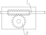
The utility model addresses the above problem the technical scheme that is adopted: the unloading device that this is used for the big yarn of fibrous glass 220kg level group, comprise vehicle frame, hydraulic actuating cylinder, control handle and lift arm, and said hydraulic actuating cylinder is installed on the vehicle frame; Said control handle links to each other with hydraulic actuating cylinder; Said lift arm is installed on the vehicle frame, and said hydraulic actuating cylinder links to each other with lift arm, it is characterized in that: also comprise circular arc carriage, transmission worm gear, transmission worm screw and hand the wheel; Said circular arc carriage is installed on the lift arm; One end of said circular arc carriage is sleeved in the transmission worm gear, said transmission worm screw and the engagement of transmission worm gear, and said hand the wheel with the transmission worm screw links to each other.Can the modulated pressure cylinder through control handle, make lift arm rise, thus the yarn group that makes the circular arc carriage arrive being positioned at eminence, handled easily, a workman operates and gets final product complete operation, labor savings cost; Can make the landing automatically from the circular arc carriage of yarn group so that the user can shake the hand upset of controlling the circular arc carriage of taking turns accurately, easily through transmission worm gear and transmission worm drive, break away from the circular arc carriage automatically by gravity; Yarn group can just in time be placed in the circular arc carriage, has certain fixation, prevents yarn group landing in moving process; Promoting arm can move up and down, and can operate the yarn group of differing heights; Use hydraulic actuating cylinder to support the lifting arm and can make the weight that promotes more than the arm carrying 220kg, and be unlikely to collapse under pressure, and durability is high.
Said transmission worm screw of the utility model and the hand side that is installed in lift arm of taking turns.The one, make that the unloading device integral structure is simple, if the transmission worm screw is installed in the centre of lift arm, need consider then whether the height of hydraulic actuating cylinder has hindered the factors such as installation site of transmission worm gear; The 2nd, make operating personal operation hand take turns convenient; Because when operating personal stands in before the unloading device, the hand hand next door that just in time is positioned at operating personal of taking turns, operating personal is raise one's hand and can be operated hand the wheel; Improved the traveling comfort of work, also helped to increase work efficiency simultaneously.
The utility model also comprises front vehicle wheel and rear wheel, and this front vehicle wheel and rear wheel all are installed on the vehicle frame.Front vehicle wheel and rear wheel are installed unloading device can be moved on the ground, and rear wheel can conveniently be regulated the working direction of unloading device.
The utility model also comprises fixed link, span chain, sprocket wheel and sprocket shaft; Said sprocket shaft is installed on the hydraulic actuating cylinder; Said sprocket wheel is sleeved on the sprocket shaft, and said fixed link is fixed on the vehicle frame, and an end of said span chain is fixed on the fixed link; The other end of this span chain is fixed on the lift arm, and this very heavy chain and sprocket links to each other.Span chain can make sprocket shaft move up and down, thereby lift arm is risen or decline.
The utility model compared with prior art, have the following advantages and effect: the utility model is sturdy and durable, applicability is wide, easily operation; Accuracy is high, energy-conserving and environment-protective, and efficiency is high; Can reduce labor intensity of operating staff, can increase the accuracy of unloading the tube operation, error rate is low.
Description of drawings
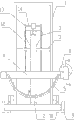
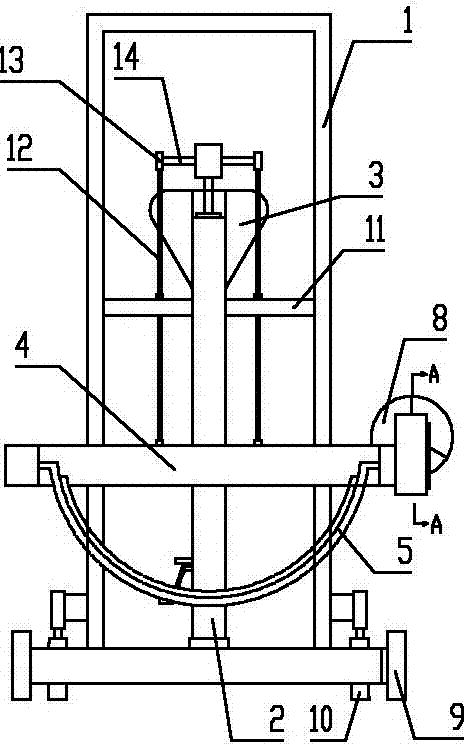
Fig. 1 is the structural representation of the utility model.
Fig. 2 is the running condition figure of the utility model.
Fig. 3 is the running condition figure of the utility model.
Fig. 4 is the A-A cross-sectional schematic.
The specific embodiment
Below in conjunction with accompanying drawing and through embodiment the utility model is done further to specify, following examples are to the explanation of the utility model and the utility model is not limited to following examples.
Referring to Fig. 1-Fig. 4; Present embodiment comprises vehicle frame 1, hydraulic actuating cylinder 2, control handle 3, lift arm 4, circular arc carriage 5, transmission worm gear 6, transmission worm screw 7, handly takes turns 8, front vehicle wheel 9, rear wheel 10, fixed link 11, span chain 12, sprocket wheel 13 and sprocket shaft 14, and the operand of present embodiment is a yarn group 15.
Hydraulic actuating cylinder 2 is installed on the vehicle frame 1, and control handle 3 links to each other with hydraulic actuating cylinder 2, and lift arm 4 is installed on the vehicle frame 1; Circular arc carriage 5 is installed on the lift arm 4, and an end of circular arc carriage 5 is sleeved in the transmission worm gear 6, transmission worm screw 7 and 6 engagements of transmission worm gear; Handly take turns 8 and link to each other with transmission worm screw 7, transmission worm screw 7 with hand take turns 8 be installed in lift arm 4 a side, front vehicle wheel 9 all is installed on the vehicle frame 1 with rear wheel 10; Sprocket shaft 14 is installed on the hydraulic actuating cylinder 2; Sprocket wheel 13 is sleeved on the sprocket shaft 14, and fixed link 11 is fixed on the vehicle frame 1, and an end of span chain 12 is fixed on the fixed link 11; The other end of this span chain 12 is fixed on the lift arm 4, and this span chain 12 links to each other with sprocket wheel 13.Hydraulic actuating cylinder 2 links to each other with lift arm 4 with sprocket shaft 14 through span chain 12, sprocket wheel 13.
Circular arc carriage 5 is that corrosion-resistant steel or other materials are processed; Circular arc carriage 5 is divided into bracket and bottom bracket; Bracket and bottom bracket pass through bolt; Bracket and bottom bracket can cooperatively interact and wherein guarantee that yarn group 15 can not drop in transportation with yarn group 15 is fixing, rock before and after also can be not significantly.
Transmission worm screw 7 with hand take turns 8 be installed in lift arm 4 a side; Among Fig. 1 transmission worm screw 7 with hand take turns 8 all be positioned at unloading device the right side; In the utility model transmission worm screw 7 with hand take turns 8 also can be positioned at unloading device the left side, transmission worm screw 7 has auto-lock function.
As shown in Figures 2 and 3, an end of circular arc carriage 5 is sleeved in the transmission worm gear 6, rotates handly to take turns 8, can make circular arc carriage 5 rotate, thereby makes the landings automatically in the circular arc carriage 5 of yarn group 15.
During use, operating personal operating control handle 3 promotes sprocket shaft 14 through hydraulic actuating cylinder 2; Sprocket shaft 14 promotes and causes lift arm 4 to be raised, and makes circular arc carriage 5 can get at yarn group 15, then yarn group 15 is put into circular arc carriage 5; Unloading device is moved to the place that needs, and the operating personal rotation is hand then takes turns 8, and circular arc carriage 5 rotates; Yarn group 15 falls, complete operation.
Above content described in this specification sheets only is the casehistory that the utility model structure is done.The utility model person of ordinary skill in the field can make various modifications or replenishes or adopt similar mode to substitute described specific embodiment; Only otherwise depart from the structure of the utility model or surmount the defined scope of these claims, all should belong to the protection domain of the utility model.