CN202180322U - Tipper for tank end-socket assembly - Google Patents
Tipper for tank end-socket assembly Download PDFInfo
- Publication number
- CN202180322U CN202180322U CN2011202797354U CN201120279735U CN202180322U CN 202180322 U CN202180322 U CN 202180322U CN 2011202797354 U CN2011202797354 U CN 2011202797354U CN 201120279735 U CN201120279735 U CN 201120279735U CN 202180322 U CN202180322 U CN 202180322U
- Authority
- CN
- China
- Prior art keywords
- tipper
- seat
- pot body
- rotating disc
- links
- Prior art date
- Legal status (The legal status is an assumption and is not a legal conclusion. Google has not performed a legal analysis and makes no representation as to the accuracy of the status listed.)
- Expired - Lifetime
Links
Images


Abstract
The utility model belongs to the equipment field of tank-installing-welding production line, specifically relating to a tipper for a tank end-socket assembly. The utility model provides a tipper for a tank end-socket assembly which has low labour intensity, higher production efficiency and safety in use. The tipper for a tank end-socket assembly comprises a moving base and the structure of the tipper is characterized in that: a tipping gear is arranged on the moving base; a rotating driving connecting sleeve connecting with a rotating disk is arranged on the tipping gear; at least three tracks are arranged on the rotating disk; a moving jack catch is arranged in each track; and each moving jack catch is connected with a syncmotor on the rotating disk through a screw.
Description
Technical field
The utility model is the apparatus field that belongs to tank body assembly welding production line; Specifically, relate to a kind of pot body closing end group to tipper.
Background technology
The end socket of present domestic manufacturing metal tub body (both tank bodies) (the round shape termination of tank body) and shell ring group to be manual group to be welded.In manufacture process, with the crane end socket that plays, and be fixed on shell ring group on the support to, spot welding, then with roller thick stick, sledgehammer position, to dress and welding, workman's physical demands is big, it is big to produce environmental noise, poor product quality, inefficiency.
Summary of the invention
The utility model is exactly to the problems referred to above, provide a kind of labor strength low, enhance productivity, pot body closing end group safe in utilization is to tipper.
For reaching the above-mentioned purpose of the utility model; The utility model adopts following technical scheme, and the utility model comprises movable base, and its structural feature movable base is provided with turning device; Turning device is provided with the rotation that links to each other with rotating disc and drives adapter sleeve; Rotating disc is provided with at least three tracks, is provided with movable jaw in the track, and movable jaw links to each other with the syncmotor on the rotating disc through leading screw.
The beneficial effect of the utility model: 1, labour intensity is low, production efficiency is high: the utility model adopts movable jaw to move in orbit; Realize clamping the function of end socket and locking; Turn over 90 ° of liters by turning device; Taken leave of existing employing manual welding system suspension ring, and by the traditional handicraft of crane lifting; In addition, end socket also can be rotated through rotating disc, realizes moving through movable base; Therefore, the utility model does not re-use crane and hangs and move; To shell ring and end socket organize to the time, the workman need not to climb on the workbench again tank body is closed tight weld bond, the group that only needs can to accomplish through PLC control shell ring and end socket is right, and the workman is freed from onerous toil, enhances productivity.
2, easy to use, improve the quality of products: the utility model can be controlled by PLC, realizes chucking, the upset and mobile of end socket.When clamping, the stretching out of three above movable jaws of syncmotor control, but make end socket automatic centering when clamping; Because movable jaw can carry out telescopic movable freely in orbit; The end socket that therefore, can adapt to the multiple diameter cylindrical shell.Because the rotating disc of the utility model can make end socket in perpendicular, rotate, realize moving in the end socket horizontal plane through movable base; Therefore, group fundamentally is guaranteed to precision, and method of operating is simple, and is easy to use.
3, safe in utilization: because the design feature of the utility model; Carry out end socket and shell ring group to the time, broken away from the overhead traveling crane handling, clamp, rotate and also realized mechanization; Existing manual welding system suspension ring have been stopped; Overhead traveling crane handling end socket, the workman carries out the right working condition of manual group along the support body climbing, has improved the security of operation.
Description of drawings
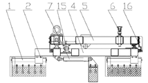
Fig. 1 is the structural representation of the utility model.
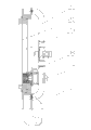
Fig. 2 is the side view of Fig. 1.
Fig. 3 is the structural representation of the utility model movable base.
Fig. 4 is the side view of Fig. 3.
Fig. 5 is the structural representation of the turning device of the utility model.
Fig. 6 is the structural representation of the utility model rotating disc and movable jaw.
Fig. 7 is the structural representation of movable jaw.
In the accompanying drawing 1 for longitudinal rail, 2 for vertically move seat, 3 for cross slide way, 4 for movable base, 5 for the laterally floating seat, 6 for buffer unit, 7 for vertical driving oil cylinder, 8 for overturning oil cylinder, 9 for turning device, 10 for rotating disc, 11 for movable jaw, 12 for latch segment, 13 for track, 14 for the workpiece buffer unit, 15 for horizontal driving oil cylinder, 16 for horizontal mobile guide plate, 17 for rotary hydraulic motor, 18 for swing pinion, 19 for ring gear, 20 for rotation drive adapter sleeve, 21 for turning supporting seat, 22 for screw, 23 for leading screw, 24 for the bevel gear group, 25 for rotating shaft, 26 for synchronous gear wheel, 27 for syncmotor, 28 for synchronous driving gear, 29 for end socket, 30 for locking cylinder, 31 is horizontal sharp type guide rail.
The specific embodiment
The utility model comprises movable base 4; Movable base 4 is provided with turning device 9; Turning device 9 is provided with the rotation that links to each other with rotating disc 10 and drives adapter sleeve 20; Rotating disc 10 is provided with at least three tracks 13, is provided with movable jaw 11 in the track 13, and movable jaw 11 links to each other with the syncmotor on the rotating disc 10 27 through leading screw 23.
Described movable base 4 comprise vertically move the seat 2, vertically move the seat 2 tops be laterally floating seat 5; Vertically move seat 2 and be arranged on the longitudinal rail 1 on ground, and link to each other with ground vertical driving oil cylinder 7; Described laterally floating seat 5 is arranged on the cross slide way 3 and horizontal sharp type guide rail 31 that vertically moves seat 2 tops, and links to each other with the horizontal driving oil cylinder that vertically moves seat 2 15.
The described both sides that vertically move seat 2 both sides and laterally floating seat 5 are provided with corresponding horizontal mobile guide plate 16; Be convenient to moving of limit lateral floating seat 5.
Described turning device 9 comprises the overturning oil cylinder 8 that is arranged on the laterally floating seat 5, and overturning oil cylinder 8 is hinged with the middle part of turning supporting seat 21, and an end of turning supporting seat 21 is hinged with laterally floating seat 5.
Be provided with buffer unit 6 corresponding to turning supporting seat 21 on the described laterally floating seat 5.
The swing pinion 18 of the rotary hydraulic motor 17 on described rotation drives the internal tooth of adapter sleeve 20 through the ring gear 19 that is attached thereto and is arranged at turning supporting seat 21 is meshed, and it is continuous with rotating disc 10 that described rotation drives adapter sleeve 20.
Syncmotor 27 on the described rotating disc 10 is meshed with synchronous gear wheel 26 through synchronous driving gear 28; Gear wheel 26 links to each other with at least three synchronous driven gears synchronously, and rotating shaft 25 ends of driven gear link to each other with leading screw 23 through bevel gear group 24 synchronously; Leading screw 23 links to each other with the screw 22 of movable jaw 11.
Described movable jaw 11 is provided with locking cylinder 30, and locking cylinder 30 links to each other with the latch segment 12 of movable jaw 11 ends.
Described rotating disc 10 is provided with workpiece buffer unit 14.
The hydraulic electric control system that links to each other with the utility model can be set, realize the functions such as reaching fine setting that moves end socket 29 positions through the hydraulic electric control system.
A course of action below in conjunction with description of drawings the utility model: reset condition: movable base 4 is at longitudinal rail 1 outermost position; Rotating disc 10, turning supporting seat 21 and movable base 4 are at parallel position; Locking cylinder 30 on the movable jaw 11 is at advanced position, latch segment 12 open-shaped attitudes.
During use; End socket 29 is fallen into rotating disc 10; Syncmotor 27 on the rotating disc 10 rotates, and drives synchronous driving gear 28, gear wheel 26 and at least three synchronous driven gears engagements synchronously, and the bevel gear group 24 that is installed in the same rotating shaft 25 with synchronous driven gear makes leading screw 23 rotations; Movable jaw 11 receives the power that the screws effect of leading screw 23 and screw 22, moves to rotating disc 10 centers along the track on the rotating disc 10 13.Drive locking cylinder 30, make latch segment 12 and end socket 29 lockings.
Drive overturning oil cylinder 8, make turning supporting seat 21 upwards overturn 90 ° around the upset hinged block.According to the operating mode needs, drive horizontal driving oil cylinder 15, make 5 years rotating discs 10 of laterally floating seat laterally move adjustment.Drive vertical driving oil cylinder 7, make movable base 4 and the turning supporting seat 21, the rotating disc 10 that are installed on the movable base 4 vertically move with shell ring approaching.
Driven in rotation hydraulic motor 17,360 ° of rotations and butt welding workpiece align around the axle center to make 10 years end sockets 29 of rotating disc, after workpiece aligns; Drive locking cylinder 30; At least three latch segments 12 open simultaneously backward, drive vertical driving oil cylinder 7, and it is tight that end socket 29 and butt welding shell ring are pasted; Hold round group to machine (another patent) rotation synchronously through PLC control rotary hydraulic motor 17 and shell ring, carry out the tack welding of end socket 29 and shell ring.
After welding is accomplished, drive syncmotor 27, make movable jaw 11 leave end socket 29, drive vertical driving oil cylinder 7, make it be back to the home position, drive overturning oil cylinder 8, make rotating disc 10, turning supporting seat 21 and movable base 4 at parallel position.
Claims (9)
1. the pot body closing end group is to tipper; Comprise movable base (4); It is characterized in that: movable base (4) is provided with turning device (9), and turning device (9) is provided with the rotation driving adapter sleeve (20) that same rotating disc (10) links to each other, and rotating disc (10) is provided with at least three tracks (13); Be provided with movable jaw (11) in the track (13), movable jaw (11) links to each other through the syncmotor (27) on the same rotating disc of leading screw (23) (10).
2. pot body closing end group according to claim 1 is characterized in that tipper: described movable base (4) comprises and vertically moves seat (2), vertically moves seat (2) top for laterally floating seat (5); Vertically move seat (2) and be arranged on the longitudinal rail (1) on ground, and link to each other with ground vertical driving oil cylinder (7); Described laterally floating seat (5) is arranged on the cross slide way (3) and horizontal sharp type guide rail (31) that vertically moves seat (2) top, and links to each other with the horizontal driving oil cylinder (15) that vertically moves seat (2).
3. pot body closing end group according to claim 2 is characterized in that tipper: the described both sides that vertically move both sides and the laterally floating seat (5) of seat (2) are provided with corresponding horizontal mobile guide plate (16).
4. pot body closing end group according to claim 3 is to tipper; It is characterized in that: described turning device (9) comprises the overturning oil cylinder (8) that is arranged on the laterally floating seat (5); The middle part of the same turning supporting seat of overturning oil cylinder (8) (21) is hinged, and an end of turning supporting seat (21) is hinged with laterally floating seat (5).
5. pot body closing end group according to claim 4 is characterized in that tipper: described laterally floating seat (5) is gone up and is provided with buffer unit (6) corresponding to turning supporting seat (21).
6. pot body closing end group according to claim 5 is to tipper; It is characterized in that: the swing pinion (18) of the rotary hydraulic motor (17) on described rotation drives the internal tooth of adapter sleeve (20) through the ring gear (19) that is attached thereto and is arranged at turning supporting seat (21) is meshed, and it is continuous that described rotation drives the same rotating disc of adapter sleeve (20) (10).
7. pot body closing end group according to claim 6 is characterized in that tipper: the syncmotor (27) on the described rotating disc (10) is meshed with synchronous gear wheel (26) through synchronous driving gear (28); Gear wheel (26) links to each other with at least three synchronous driven gears synchronously, and rotating shaft (25) end of driven gear links to each other through the same leading screw of bevel gear group (24) (23) synchronously; The screw (22) of the same movable jaw of leading screw (23) (11) links to each other.
8. pot body closing end group according to claim 7 is characterized in that tipper: described movable jaw (11) is provided with locking cylinder (30), and the latch segment (12) of the same movable jaw of locking cylinder (30) (11) end links to each other.
9. pot body closing end group according to claim 8 is characterized in that tipper: described rotating disc (10) is provided with workpiece buffer unit (14).
Priority Applications (1)
| Application Number | Priority Date | Filing Date | Title |
|---|---|---|---|
| CN2011202797354U CN202180322U (en) | 2011-08-03 | 2011-08-03 | Tipper for tank end-socket assembly |
Applications Claiming Priority (1)
| Application Number | Priority Date | Filing Date | Title |
|---|---|---|---|
| CN2011202797354U CN202180322U (en) | 2011-08-03 | 2011-08-03 | Tipper for tank end-socket assembly |
Publications (1)
| Publication Number | Publication Date |
|---|---|
| CN202180322U true CN202180322U (en) | 2012-04-04 |
Family
ID=46173371
Family Applications (1)
| Application Number | Title | Priority Date | Filing Date |
|---|---|---|---|
| CN2011202797354U Expired - Lifetime CN202180322U (en) | 2011-08-03 | 2011-08-03 | Tipper for tank end-socket assembly |
Country Status (1)
| Country | Link |
|---|---|
| CN (1) | CN202180322U (en) |
Cited By (3)
| Publication number | Priority date | Publication date | Assignee | Title |
|---|---|---|---|---|
| CN106378576A (en) * | 2015-07-31 | 2017-02-08 | 南通中集罐式储运设备制造有限公司 | Pot type container assembly table and method |
| CN108453458A (en) * | 2018-04-18 | 2018-08-28 | 杜宗英 | The end socket welding processing tooling of ammonia tank |
| CN113814641A (en) * | 2021-11-01 | 2021-12-21 | 内蒙古特变电工能源装备有限公司 | Special flange and tower section assembling machine for wind power tower cylinder manufacturing and method for applying special flange and tower section assembling machine |
-
2011
- 2011-08-03 CN CN2011202797354U patent/CN202180322U/en not_active Expired - Lifetime
Cited By (6)
| Publication number | Priority date | Publication date | Assignee | Title |
|---|---|---|---|---|
| CN106378576A (en) * | 2015-07-31 | 2017-02-08 | 南通中集罐式储运设备制造有限公司 | Pot type container assembly table and method |
| CN106378576B (en) * | 2015-07-31 | 2019-04-30 | 南通中集罐式储运设备制造有限公司 | Tank container assembly bench and assembly method |
| CN109773400A (en) * | 2015-07-31 | 2019-05-21 | 南通中集罐式储运设备制造有限公司 | Tank container assembly bench and assembly method |
| CN109773400B (en) * | 2015-07-31 | 2020-09-11 | 南通中集罐式储运设备制造有限公司 | Tank container assembly stand and assembly method |
| CN108453458A (en) * | 2018-04-18 | 2018-08-28 | 杜宗英 | The end socket welding processing tooling of ammonia tank |
| CN113814641A (en) * | 2021-11-01 | 2021-12-21 | 内蒙古特变电工能源装备有限公司 | Special flange and tower section assembling machine for wind power tower cylinder manufacturing and method for applying special flange and tower section assembling machine |
Similar Documents
| Publication | Publication Date | Title |
|---|---|---|
| CN203726485U (en) | Transferring manipulator | |
| CN204108559U (en) | Pot body closing end welder | |
| CN103465247B (en) | The air-conditioning machine of falling erects machine manipulator | |
| CN204209580U (en) | Tire automatic clamping device | |
| CN104924170A (en) | Improved online burr removing device for wheel valve hole | |
| CN213765521U (en) | Anchor clamps for machining | |
| CN202180322U (en) | Tipper for tank end-socket assembly | |
| CN204893261U (en) | Five welding manipulators | |
| CN204639842U (en) | A kind of online burr remover in wheel valve hole of improvement | |
| CN204565464U (en) | A kind of rush-harvesting and rush-planting wheel rim bonding machine | |
| CN113210946B (en) | Welding machine feeding manipulator for welding anchor chain | |
| CN204277365U (en) | Full-automatic steel cylinder welder | |
| CN203956304U (en) | Fillet welding automatic welding device in drilling platform leg tooth bar and semi-circular plate | |
| CN209503389U (en) | A kind of coalcutter sprocket wheel socket repair apparatus | |
| CN209651387U (en) | A kind of automatic charging workpiece gripper device | |
| CN216097274U (en) | Turning device for welding steel structural part | |
| CN203791607U (en) | Drilling device for vehicle wheel sprues | |
| CN2782291Y (en) | Beam workpiece side tilter | |
| CN105479290A (en) | Multifunctional wheel deburring device | |
| CN216129199U (en) | Hoisting equipment for transferring gears | |
| CN104889625A (en) | Reinforcing ring automatic feeding device used for welding passenger vehicle axle housing and reinforcing ring | |
| CN211109837U (en) | Column type rotary power-assisted arm device | |
| CN205237747U (en) | Multi -function vehicle wheel burring device | |
| CN113732683A (en) | Automatic assembly system of assembling of small pipe diameter | |
| CN202464748U (en) | Steering gear for train wheel blank transportation |
Legal Events
| Date | Code | Title | Description |
|---|---|---|---|
| C14 | Grant of patent or utility model | ||
| GR01 | Patent grant | ||
| CX01 | Expiry of patent term | ||
| CX01 | Expiry of patent term |
Granted publication date: 20120404 |