CN202047369U - Case-type steel main beam rectifying device used during construction - Google Patents
Case-type steel main beam rectifying device used during construction Download PDFInfo
- Publication number
- CN202047369U CN202047369U CN2011200161857U CN201120016185U CN202047369U CN 202047369 U CN202047369 U CN 202047369U CN 2011200161857 U CN2011200161857 U CN 2011200161857U CN 201120016185 U CN201120016185 U CN 201120016185U CN 202047369 U CN202047369 U CN 202047369U
- Authority
- CN
- China
- Prior art keywords
- steel
- main beam
- steel main
- case
- rectifying device
- Prior art date
- Legal status (The legal status is an assumption and is not a legal conclusion. Google has not performed a legal analysis and makes no representation as to the accuracy of the status listed.)
- Expired - Fee Related
Links
- 229910000831 Steel Inorganic materials 0.000 title claims abstract description 64
- 239000010959 steel Substances 0.000 title claims abstract description 64
- 238000010276 construction Methods 0.000 title claims abstract description 15
- 244000261422 Lysimachia clethroides Species 0.000 claims description 11
- 239000000203 mixture Substances 0.000 claims description 2
- 238000004519 manufacturing process Methods 0.000 abstract description 2
- 239000002699 waste material Substances 0.000 abstract description 2
- 238000009434 installation Methods 0.000 description 5
- 230000000694 effects Effects 0.000 description 2
- 238000000034 method Methods 0.000 description 2
- 239000000047 product Substances 0.000 description 2
- 239000000729 antidote Substances 0.000 description 1
- 230000009286 beneficial effect Effects 0.000 description 1
- 238000005516 engineering process Methods 0.000 description 1
- 239000012467 final product Substances 0.000 description 1
- 230000000977 initiatory effect Effects 0.000 description 1
- 239000000725 suspension Substances 0.000 description 1
- 230000017105 transposition Effects 0.000 description 1
- 238000003466 welding Methods 0.000 description 1
Images


Landscapes
- Bridges Or Land Bridges (AREA)
Abstract
The utility model discloses a case-type steel main beam rectifying device used during construction. When the conventional steel main beams twist during actual production application, no existing equipment can be used for rectifying the steel main beams, so that the service life of a bridge is shortened, economic waste is caused and safety hazard is caused. The case-type steel main beam rectifying device used during the construction structurally comprises a steel cross beam (1) of which the two ends are connected with the steel main beam, and a steel oblique beam (3) which is connected with the steel main beam (2), wherein jacks (4) are arranged at the two ends of the lower part of the steel cross beam; the lower part of the steel cross beam is connected with a steel post (5); and the steel post is connected with the jack through a steel threaded wire (6). The case-type steel main beam rectifying device is used for bridge construction.
Description
Technical field:
The present invention relates to a kind of field of construction of road bridges, be specifically related to a kind of construction raising middle flask shaped steel girder apparatus for correcting.
Background technology:
When existing box steel girder produces when reversing in actual applications, there is not ready-made equipment to proofread and correct, to put the application life that makes bridge and reduce, economy causes waste, and safety causes a hidden trouble.
Summary of the invention:
The purpose of this invention is to provide a kind of extraordinary member of torsion phenomenon effect and job practices of correcting girder steel.
Above-mentioned purpose realizes by following technical scheme:
A kind of construction raising middle flask shaped steel girder apparatus for correcting, two ends connect the gooseneck of described steel girder, the steel cant beam that is connected with described steel girder, described jack is equipped with at two ends, described gooseneck bottom, described gooseneck bottom connects steel column, and described steel column connects described jack by the steel streakline.
Described construction raising middle flask shaped steel girder apparatus for correcting, construction raising middle flask shaped steel girder apparatus for correcting, described steel column diameter is greater than 530 millimeters.
Beneficial effect:
1. the present invention can correct the position deviation of girder steel and reverse, effective, economical and practical, install simple.
Reversing of the rectifiable high-altitude of the present invention heavy section steel girder steel oversimplified work progress, raises the efficiency.
The present invention has rational in infrastructure, safe and reliable advantage, and this product can repeat practicality, and is economical and practical.
The present invention applies counter-force by the large-tonnage hydraulic jack, and the precision of adjustment can be accurate in 1 millimeter, has guaranteed quality simultaneously.
The present invention adopts the combination of fritter steel plate to get final product this fastener of welding production, has reduced engineering cost.
The present invention is low from heavy and light, labour intensity, reaches energy saving purposes.
Description of drawings:
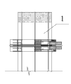
Accompanying drawing 1 is the structure chart of this product.
Accompanying drawing 2 is elevation of accompanying drawing 1.
Accompanying drawing 3 is plan views of accompanying drawing 1.
The specific embodiment:
Embodiment 1:
Construction raising middle flask shaped steel girder antidote, often produce girder transposition situation in the large-scale bridge grain construction, method of the present invention be at box steel girder when generation is reversed, employing applies counter-force under the steel girder of installation, counter-force acts on the lower edge of box steel girder by the shaped steel fastener, the opposite side of shaped steel fastener connects jack, when the jack pressurization applies counter-force, can produce the method for the trend reverse to box steel girder, to correct the position deviation of the reversing of girder steel, rectifiable girder steel.
Embodiment 2:
A kind of construction raising middle flask shaped steel girder apparatus for correcting, its composition comprises: two ends connect the gooseneck 1 of described steel girder, the steel cant beam 3 that is connected with described steel girder 2, described jack 4 is equipped with at two ends, described gooseneck bottom, described gooseneck bottom connects steel column 5, and described steel column connects described jack 4 by steel streakline 6.Described steel column diameter is greater than 530 millimeters.
When carrying out the installation of large bridge superposed beam sections, the installation of gooseneck is comparatively difficult, and main cause is that box steel girder has produced reversing to the inside under the effect of concrete slab, suspension cable pulling force, the deadweight of bridge floor loop wheel machine etc.Through multinomial public relations, we test employing and apply anti-top under the goosenecks of installation, the support reaction on anti-top acts on the lower edge outside of box steel girder by the shaped steel fastener, when the jack pressurization applies anti-top, box steel girder is produced the trend reverse laterally, in order to offset steel girder reversing to the inside.Finally finished the installation of bridge superposed beam sections, belonged to the world initiation.
Claims (1)
1.
A kind of construction raising middle flask shaped steel girder apparatus for correcting, its composition comprises: two ends connect the gooseneck of described steel girder, it is characterized in that: the steel cant beam that is connected with described steel girder, described jack is equipped with at two ends, described gooseneck bottom, described gooseneck bottom connects steel column, and described steel column connects described jack by the steel streakline.
2. construction raising middle flask shaped steel girder apparatus for correcting according to claim 2, it is characterized in that: described steel column diameter is greater than 530 millimeters.
Priority Applications (1)
| Application Number | Priority Date | Filing Date | Title |
|---|---|---|---|
| CN2011200161857U CN202047369U (en) | 2011-01-19 | 2011-01-19 | Case-type steel main beam rectifying device used during construction |
Applications Claiming Priority (1)
| Application Number | Priority Date | Filing Date | Title |
|---|---|---|---|
| CN2011200161857U CN202047369U (en) | 2011-01-19 | 2011-01-19 | Case-type steel main beam rectifying device used during construction |
Publications (1)
| Publication Number | Publication Date |
|---|---|
| CN202047369U true CN202047369U (en) | 2011-11-23 |
Family
ID=44987683
Family Applications (1)
| Application Number | Title | Priority Date | Filing Date |
|---|---|---|---|
| CN2011200161857U Expired - Fee Related CN202047369U (en) | 2011-01-19 | 2011-01-19 | Case-type steel main beam rectifying device used during construction |
Country Status (1)
| Country | Link |
|---|---|
| CN (1) | CN202047369U (en) |
Cited By (2)
| Publication number | Priority date | Publication date | Assignee | Title |
|---|---|---|---|---|
| CN102071648A (en) * | 2011-01-19 | 2011-05-25 | 龙建路桥股份有限公司 | Method and device for correcting box steel girder in construction |
| CN111877168A (en) * | 2020-07-20 | 2020-11-03 | 长沙理工大学 | Torsion correction method for lattice type steel main beam of combined cable-stayed bridge |
-
2011
- 2011-01-19 CN CN2011200161857U patent/CN202047369U/en not_active Expired - Fee Related
Cited By (3)
| Publication number | Priority date | Publication date | Assignee | Title |
|---|---|---|---|---|
| CN102071648A (en) * | 2011-01-19 | 2011-05-25 | 龙建路桥股份有限公司 | Method and device for correcting box steel girder in construction |
| CN102071648B (en) * | 2011-01-19 | 2014-12-10 | 龙建路桥股份有限公司 | Method and device for correcting box steel girder in construction |
| CN111877168A (en) * | 2020-07-20 | 2020-11-03 | 长沙理工大学 | Torsion correction method for lattice type steel main beam of combined cable-stayed bridge |
Similar Documents
| Publication | Publication Date | Title |
|---|---|---|
| CN204875552U (en) | Frame bridge crane vertical lift structure | |
| CN203979647U (en) | A kind of detachable recycling guide rail pipe perforator | |
| CN105544406B (en) | Bailey beam is sliding to remove device and its method for dismounting | |
| CN202482772U (en) | Collapse-proof stop block mounting system for railway bridge | |
| CN202081427U (en) | Embedded bolt positioning device for tower crane foundation | |
| CN102071648B (en) | Method and device for correcting box steel girder in construction | |
| CN202290893U (en) | Straightening machine for H section steel flange slab | |
| CN202302300U (en) | Combined pipeline mounting operation platform | |
| CN204474202U (en) | Large-tonnage steel member integrated hoisting fixture | |
| CN203462075U (en) | Furnace-supporting platform frame of converter | |
| CN203430027U (en) | Adjustable large steel formwork | |
| CN202296886U (en) | Hoisting device for installing oversized radial gate of hydropower station | |
| CN202644407U (en) | Demoulding device for bottom plate bracket of capping beam constructed by hoop method | |
| CN204074826U (en) | A kind of engineering steel form distortion adjusting device | |
| CN203530850U (en) | Track device of forward bridge girder erection machine | |
| CN203808535U (en) | Device for adjusting column axis in cup-rim-shaped building | |
| CN204975846U (en) | Ram quick -witted basic cantilever crane group by force to frock | |
| CN102049429B (en) | JCOE forming machine master cylinder installation method | |
| CN204212071U (en) | A kind of pier stud anchor structure | |
| CN205312885U (en) | Gantry crane span guiding mechanism | |
| CN204975845U (en) | Ram cantilever crane group of set -top portion by force to frock | |
| CN104278848A (en) | Bailey beam disassembly trailer | |
| CN217172992U (en) | A stand up hoist for welding process of big cross-section I-shaped steel roof beam | |
| CN223422234U (en) | On-site maintenance auxiliary device for electric hoist wheels | |
| CN217269060U (en) | Auxiliary dismounting device for sliding Bailey beam capable of walking on beam |
Legal Events
| Date | Code | Title | Description |
|---|---|---|---|
| C14 | Grant of patent or utility model | ||
| GR01 | Patent grant | ||
| CF01 | Termination of patent right due to non-payment of annual fee |
Granted publication date: 20111123 Termination date: 20170119 |
|
| CF01 | Termination of patent right due to non-payment of annual fee |