CN201990494U - Energy-saving polycrystalline silicon reduction furnace - Google Patents
Energy-saving polycrystalline silicon reduction furnace Download PDFInfo
- Publication number
- CN201990494U CN201990494U CN2011201330157U CN201120133015U CN201990494U CN 201990494 U CN201990494 U CN 201990494U CN 2011201330157 U CN2011201330157 U CN 2011201330157U CN 201120133015 U CN201120133015 U CN 201120133015U CN 201990494 U CN201990494 U CN 201990494U
- Authority
- CN
- China
- Prior art keywords
- polycrystalline silicon
- thermoscreen
- chassis
- furnace
- furnace wall
- Prior art date
- Legal status (The legal status is an assumption and is not a legal conclusion. Google has not performed a legal analysis and makes no representation as to the accuracy of the status listed.)
- Expired - Fee Related
Links
Images


Classifications
-
- Y—GENERAL TAGGING OF NEW TECHNOLOGICAL DEVELOPMENTS; GENERAL TAGGING OF CROSS-SECTIONAL TECHNOLOGIES SPANNING OVER SEVERAL SECTIONS OF THE IPC; TECHNICAL SUBJECTS COVERED BY FORMER USPC CROSS-REFERENCE ART COLLECTIONS [XRACs] AND DIGESTS
- Y02—TECHNOLOGIES OR APPLICATIONS FOR MITIGATION OR ADAPTATION AGAINST CLIMATE CHANGE
- Y02P—CLIMATE CHANGE MITIGATION TECHNOLOGIES IN THE PRODUCTION OR PROCESSING OF GOODS
- Y02P20/00—Technologies relating to chemical industry
- Y02P20/10—Process efficiency
Landscapes
- Silicon Compounds (AREA)
Abstract
The utility model relates to an energy-saving polycrystalline silicon reduction furnace. The reduction furnace comprises a bell jar-shaped furnace wall, a base arranged below the furnace wall, an electrode arranged on the base and a silicon core rod mounted on the electrode, wherein a raw material gas intake port and a tail gas discharge port are also formed on the base. The utility model is characterized in that a bell jar-type heat shield is arranged on the base, is concentric to the furnace wall and is used for covering the silicon core rod; the heat shield comprises a cylindrical part and a top part which is connected with the cylindrical part and provided with a through hole; the raw material gas intake port is formed on the base and positioned between the cylindrical part of the heat shield and the furnace wall; and the tail gas discharge port is positioned in the center of the base. In the polycrystalline silicon reduction furnace provided by the utility model, the polycrystalline silicon is covered by the heat shield, so as to greatly reduce the heat loss, allow a raw material gas to be pretreated and increase the primary conversion rate of silicon.
Description
Technical field
The utility model relates to a kind of manufacturing installation of polysilicon, particularly relates to a kind of energy-saving polycrystalline silicon reducing furnace that carries out the chemical vapour deposition polysilicon with trichlorosilane on the silicon mandrel surface of heating.
Background technology
High-purity polycrystalline silicon generally adopts Siemens Method to make, and will contain chlorosilane, contacts with the silicon plug of heating as the unstripped gas of the mixed gas of trichlorosilane and hydrogen, makes the unstripped gas decomposition and/or is reduced, and separates out polysilicon at the silicon mandrel surface.
Adopting the improvement Siemens Method to generate the common reduction furnace that adopts of polysilicon is a kind of bell jar type furnace wall that water coolant is arranged, with be arranged on bell jar type furnace wall below the chassis of water coolant arranged, the chassis is provided with many counter electrode and the silicon plug that is installed on the electrode, unstripped gas supplies in the reduction furnace from the chassis, and the tail gas relief outlet also is arranged on the chassis.Unstripped gas and reducing gas are as hydrogen, at silicon rod or refractory metal silk energising resistive heating to 1050 ℃~1200 ℃ of scopes, chemical vapour deposition polysilicon.Because the temperature height of polycrystalline silicon rod, and long reaction time, power consumption is big, thermal radiation and gaseous exchange, and a large amount of heat is taken away by the water coolant of furnace wall, and this has also increased the refrigerative difficulty.In addition, because unstripped gas admission port and venting port all are arranged on the chassis, do not separate, part material gas enters reduction furnace and also participates in reaction and just be discharged from, and like this, the trichlorosilane transformation efficiency is low.
The clear 60-77115 Gong of Japanese Patent Gong Open Open a kind of manufacturing installation of HIGH-PURITY SILICON, with this device high purity polycrystalline silicon is made in silane, chlorosilane thermolysis or hydrogen reduction, this device inside is provided with well heater, reactor outer wall inboard is provided with the inwall of band gap, be filled with saccharoid between outer wall and inwall, as thermofin, can reduce electricity consumption with this filling bed significantly.Japanese Patent Te Open 2001-294416 Gong Open a kind of device of producing polycrystalline silicon rod, the silicon plug is upright to be located in the airtight reactor, heat, the unstripped gas thermolysis that imports is separated out polysilicon on the silicon plug, this reactor linings has the thermofin that is selected from carbon, silicon nitride, quartz, silicon carbide, zirconium white or their matrix material system.Above-mentioned technology can reduce electricity consumption, but its unstripped gas of above-mentioned technology and reduction back tail gas cause turbulence all from the reaction container bottom turnover, and part material gas is not also participated in reaction and just has been discharged from.
Chinese patent CN101445241A discloses a kind of admission port and venting port of reducing furnace for polycrystalline silicon production, admission port is installed on the base, stretches into 100~300mm above the stove inner bottom part, and the top is blocked, open a hydraucone at the closure plate center, or open 3~6 spirals at sidewall and tangentially export.Venting port is fixed on 5~7 mouth of pipe formula structures on the end socket of cover top portion.This structure obviously can cause the energy to dissipate in a large number.
Summary of the invention
In view of the problem that above-mentioned prior art exists, the purpose of this utility model provides a kind of energy-conservation from high polycrystalline silicon reducing furnace of transformation efficiency of trichlorosilane.
The utility model adopts following structure in order to address the above problem:
A kind of energy-saving polycrystalline silicon reducing furnace, comprise the bell-jar furnace wall, be arranged on the chassis of below, furnace wall, be arranged on electrode and the silicon plug that is installed on the electrode on the chassis, unstripped gas supplies in the reduction furnace from the admission port on chassis, tail gas is discharged from the tail gas relief outlet on the chassis, it is characterized in that: above-mentioned chassis is provided with one and the concentric bell-jar thermoscreen in furnace wall, this bell-jar thermoscreen surrounds the silicon plug of growth, described bell-jar thermoscreen is formed by cylindrical portion with the top by through hole that described cylindrical portion is joined, and described unstripped gas admission port is arranged on the cylindrical portion and the chassis between the furnace wall of thermoscreen; Described venting port is arranged on center chassis.
The internal diameter of described thermoscreen cylindrical portion is preferably 5~15 cm greater than the maximum occupy-place diameter of the back polycrystalline silicon rod 5cm at least that grows, and the height of thermoscreen cylindrical portion is higher than growth back polysilicon maximum occupy-place 10cm highly at least, is preferably 10~40cm.
Wherein, the unstripped gas admission port has 8 at least, and be evenly distributed on the chassis with the concentric same circumference of reduction furnace on.
Wherein, at least 4 of described through holes are evenly distributed on the thermoscreen top.
According to the utility model, unstripped gas is by the cylindrical portion of described thermoscreen and the admission port on the chassis between the bell-jar furnace wall,, enter the reduction reaction district from bottom to top, by the polycrystalline silicon rod surface deposition growing polycrystalline silicon of thermolysis in the energising heating from the through hole at described thermoscreen top.
Polycrystalline silicon reducing furnace of the present utility model adopts thermoscreen to cover polysilicon, thereby reduces calorific loss significantly, and makes unstripped gas obtain preheating, and unstripped gas can improve a transformation efficiency of silicon by the reaction zone path length.
Description of drawings
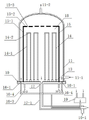
Fig. 1 is the structural representation sketch of polycrystalline silicon reducing furnace of the present invention;
Fig. 2 is a cross section shown in Figure 1, the distribution schematic diagram of expression unstripped gas admission port and tail gas relief outlet;
Fig. 3 is a thermoscreen top through hole distribution schematic diagram.
Embodiment
Below, based on accompanying drawing embodiment of the present utility model is described.
Fig. 1 shows the synoptic diagram of polycrystalline silicon reducing furnace of the present invention, and described polycrystalline silicon reducing furnace comprises: the chassis 10 of band cooling water jecket, and there is entrance of cooling water 10-1 on the chassis, cooling water outlet 10-2; Be seated in the bell-jar furnace wall 11 that cooling water sandwich is arranged on the chassis, wherein water coolant enters from following water-in 11-1, flows out from pushing up 11-2; The reduction furnace chamber is formed on bell-jar furnace wall 11 and chassis 10; Have pair of electrodes on the chassis at least, many persons do not limit, and electrode passes chassis 10 and puts in reaction zone 18 and join with electrode chuck 13, and electrode chuck 13 be the graphite manufacturing, and 14 settings of silicon plug are installed on the electrode chuck 13; Lay bell-jar thermoscreen 15 on the chassis, thermoscreen 15 surrounds all polycrystalline silicon rods, forms the reaction zone of growing polycrystalline silicon; Described bell-jar thermoscreen comprises cylindrical portion 15-1 and top 15-2, and a plurality of communicating pores 15-3 that are evenly distributed are arranged at the top; Be provided with equally distributed 12 unstripped gas admission port 16-1 outside bell-jar thermoscreen 15 and on the chassis between the bell-jar furnace wall 11; Be provided with venting port 17 at center chassis; Gas mixing chamber 19, after unstripped gas enters mixing section 19 mixing, after the tail gas preheating of gas exhaust duct 17-1,, enter reduction furnace chamber 18 through unstripped gas admission port 16-1 from 12 (only illustrating 2 figure) standpipe 16-4 that erect through coil pipe 16-3 through discharging.
Fig. 2 is the cross-sectional view of the reduction furnace of Fig. 1, the example that expression raw material inlet, venting port and silicon rod distribute, wherein unstripped gas all the unstripped gas admission port 16-1 from the chassis between thermoscreen and the bell-jar furnace wall enter reduction furnace, from between thermoscreen and the furnace wall from bottom to top, enter the example of reaction zone 18 again from the through hole 15-3 at the top of thermoscreen.
Wherein, described bell-jar thermoscreen comprises cylindrical portion 15-1 and top 15-2, the cylindrical portion external diameter of bell-jar thermoscreen is than the little 8 ~ 15cm of bell-jar furnace wall internal diameter, and the internal diameter of cylindrical portion is preferably 5 ~ 15 cm than the big at least 5cm of the maximum occupy-place diameter of polysilicon after growing; The high at least 10cm of the highest occupy-place of the polysilicon after the cylindrical portion aspect ratio growth is preferably 10 ~ 40 cm, and the through hole at top has 4 at least, be preferably more a plurality of, preferred a plurality of through hole uniform distribution; Wherein the size to through hole does not have strict restriction, and the area that preferably is provided with through hole accounts for 1//40 ~ 1/10 of entire top area.Fig. 3 represents the through hole at bell-jar thermoscreen top.The material of making described thermoscreen preferably uses high temperature resistant and at high temperature seldom produces the material of volatile matter, as tungsten, molybdenum, high temperature resistant stainless steel or their alloy sheets, and stainless steel plate such as 310S, Cr20Ni80 alloy sheets.Polished finish is carried out on described thermoscreen surface.
Wherein, as the silicon plug of deposit spathic silicon such as the Π font silicon rod among Fig. 1, peg graft by the silicon rod 14-1 of two long settings and the crossbeam silicon rod 14-2 boring of a weak point, or peg graft with the recess groove.Feed electric current by electrode and make silicon rod reach 1050 ℃ ~ 1200 ℃ high temperature, thermolysis of silicon-containing compound gas or hydrogen reduction be deposit spathic silicon on the silicon rod of heating.
As shown in Figure 1, unstripped gas enters gas mixing chamber 19, mixed unstripped gas is by after carrying out preheating from venting port 17 tail gas discharged, after by pipeline described mixed gas being drawn from pipeline 17-1, with a ring-type coil pipe 16-3 with mixed gas respectively from as Fig. 1 or uniform standpipe 16-4 shown in Figure 2, send between the bell-jar thermoscreen 15 and bell-jar furnace wall 11 of Reaktionsofen through unstripped gas admission port 16-1, from bottom to top, unstripped gas obtains further preheating again; The silicon-containing material mixed gas arrives the through hole 15-3 that is turned back from the thermoscreen top at the reduction furnace top and enters reaction zone 18, unstripped gas must just arrive venting port through the whole height of reaction zone, like this, unstripped gas pyrolysated path length, trichlorosilane transformation efficiency height.
Embodiment
Embodiment 1
Use construction recovery stove as depicted in figs. 1 and 2, with two long silicon plug 14-1 and a short silicon plug 14-2 is one group, it is the upper end that one end of long silicon plug is fined away, short silicon plug punching two ends matches with it, to be one group in the most advanced and sophisticated patchhole, totally 28 groups of silicon plugs 14 be straightened and be installed on the electrode chuck 13; Successively thermoscreen 15 and bell-jar furnace wall 11 are placed on the chassis 10; Behind nitrogen replacement reduction furnace chamber, use hydrogen exchange reduction furnace chamber again, become energising heating behind the conductor with graphite heater or refractory metal well heater preheating silicon plug 14, silicon plug 14 is heated to 1100 ℃ ~ 1200 ℃; The silicon-containing material mixed gas arrives the through hole 15-3 that is turned back from the thermoscreen top at the reduction furnace top and enters reaction zone 18, trichlorosilane decomposes deposit spathic silicon on the silicon plug, make the silicon diameter of mandrel become big, this part unstripped gas must just arrive venting port through the whole height of reaction zone.The logical nitrogen of cooling cooled off after polysilicon deposition reached predetermined diameter, removed bell-jar furnace wall 11 and bell-jar thermoscreen 15, took polycrystalline silicon rod 14 away.Transformation efficiency of trichlorosilane and unit weight polysilicon power consumption such as table 1.
Comparative example 1
Use the existing reduction furnace that has 28 counter electrode equally, just do not have the bell-jar thermoscreen, unstripped gas and tail gas all are from the chassis turnover, carry out polycrystalline silicon growth.Transformation efficiency of trichlorosilane and unit weight polysilicon power consumption such as table 1.
Table 1
| Reduction furnace | Trichlorosilane transformation efficiency % | Single stove power consumption kwh/kg |
| Embodiment 1 | 12.8 | 70.3 |
| Comparative example 1 | 10.8 | 80.1 |
The above, it only is preferred embodiment of the present invention, be not that the present invention is done any pro forma restriction, any those skilled in the art, in not breaking away from the technical solution of the present invention scope, make many changes or be modified to the equivalent example of equivalent variations when the technology contents that can utilize above-mentioned announcement, all still belong in the new technical scheme scope of the present invention.
Claims (4)
1. energy-saving polycrystalline silicon reducing furnace, comprise bell jar type furnace wall, be arranged on the chassis of below, furnace wall, be arranged on electrode and the silicon plug that is installed on the electrode on the chassis, also be provided with unstripped gas admission port and tail gas venting port on the chassis, it is characterized in that: above-mentioned chassis be provided with one with the furnace wall concentric and cylinder-shaped bell bell-type thermoscreen that the silicon plug is covered, this thermoscreen is formed by cylindrical portion with the top by through hole that described cylindrical portion is joined; Above-mentioned raw materials gas admission port is arranged on the cylindrical portion and the chassis between the furnace wall of thermoscreen, and the tail gas venting port is located at center chassis.
2. according to the described energy-saving polycrystalline silicon reducing furnace of claim 1, it is characterized in that: above-mentioned raw materials gas admission port has 8 at least, and be evenly distributed on the concentric same circumference of reduction furnace on.
3. according to the described energy-saving polycrystalline silicon reducing furnace of claim 1, it is characterized in that: the internal diameter of described thermoscreen cylindrical portion is greater than the maximum occupy-place diameter of the back polycrystalline silicon rod 5cm at least that grows, be preferably 5~15 cm, the height of thermoscreen cylindrical portion is higher than the maximum occupy-place of growth back polycrystalline silicon rod 10cm highly at least, is preferably 10~40cm.
4. according to the described energy-saving polycrystalline silicon reducing furnace of claim 1, it is characterized in that: at least 4 of described through holes are evenly distributed on the thermoscreen top.
?
Priority Applications (1)
| Application Number | Priority Date | Filing Date | Title |
|---|---|---|---|
| CN2011201330157U CN201990494U (en) | 2011-04-29 | 2011-04-29 | Energy-saving polycrystalline silicon reduction furnace |
Applications Claiming Priority (1)
| Application Number | Priority Date | Filing Date | Title |
|---|---|---|---|
| CN2011201330157U CN201990494U (en) | 2011-04-29 | 2011-04-29 | Energy-saving polycrystalline silicon reduction furnace |
Publications (1)
| Publication Number | Publication Date |
|---|---|
| CN201990494U true CN201990494U (en) | 2011-09-28 |
Family
ID=44666988
Family Applications (1)
| Application Number | Title | Priority Date | Filing Date |
|---|---|---|---|
| CN2011201330157U Expired - Fee Related CN201990494U (en) | 2011-04-29 | 2011-04-29 | Energy-saving polycrystalline silicon reduction furnace |
Country Status (1)
| Country | Link |
|---|---|
| CN (1) | CN201990494U (en) |
Cited By (2)
| Publication number | Priority date | Publication date | Assignee | Title |
|---|---|---|---|---|
| CN102515167A (en) * | 2011-11-29 | 2012-06-27 | 天津大学 | Periodical alternatively operating polycrystalline silicon reduction furnace equipped with inner heat-insulating barrel and operation method |
| CN109682221A (en) * | 2018-12-18 | 2019-04-26 | 中国恩菲工程技术有限公司 | Heating plant and heat-exchange system |
-
2011
- 2011-04-29 CN CN2011201330157U patent/CN201990494U/en not_active Expired - Fee Related
Cited By (2)
| Publication number | Priority date | Publication date | Assignee | Title |
|---|---|---|---|---|
| CN102515167A (en) * | 2011-11-29 | 2012-06-27 | 天津大学 | Periodical alternatively operating polycrystalline silicon reduction furnace equipped with inner heat-insulating barrel and operation method |
| CN109682221A (en) * | 2018-12-18 | 2019-04-26 | 中国恩菲工程技术有限公司 | Heating plant and heat-exchange system |
Similar Documents
| Publication | Publication Date | Title |
|---|---|---|
| CN102205967A (en) | Energy-saving polysilicon reduction furnace and manufacturing method for polysilicon | |
| CN101870471B (en) | High-efficiency large polycrystalline silicon reducing furnace | |
| CN201512418U (en) | Polycrystalline silicon reducing furnace | |
| CN102424386B (en) | Efficient energy-saving type polysilicon reduction furnace | |
| CN102134745B (en) | Reactor and system for producing polycrystalline silicon | |
| CN202046891U (en) | Energy-saving polysilicon reduction furnace with heat shield | |
| CN106283180A (en) | The manufacture method of polysilicon and the manufacture method of monocrystal silicon | |
| CN201125165Y (en) | Polysilicon reducing furnace having double cooling system | |
| CN201473329U (en) | Polysilicon reducing furnace | |
| CN201990494U (en) | Energy-saving polycrystalline silicon reduction furnace | |
| CN102796995A (en) | Vapor deposition furnace and method for preparing pyrolytic boron nitride product | |
| CN201746331U (en) | Polysilicon reducing surface | |
| CN101973551B (en) | Polysilicon reducing furnace | |
| CN201162065Y (en) | Novel polysilicon reduction furnace | |
| CN108910890A (en) | A kind of polycrystalline silicon reducing furnace and its application method | |
| CN102515167B (en) | Periodical alternatively operating polycrystalline silicon reduction furnace equipped with inner heat-insulating barrel and operation method | |
| WO2018076139A1 (en) | Method for producing polycrystalline silicon and method for producing monocrystalline silicon | |
| CN209242690U (en) | Electronic-grade polycrystalline silicon reduction furnace chassis and reduction furnace | |
| CN201214631Y (en) | Polysilicon reduction furnace | |
| CN216863655U (en) | Silane thermal decomposition furnace capable of promoting uniform and compact deposition of zone-melting-level polycrystalline silicon | |
| CN201648567U (en) | Polysilicon decomposing furnace | |
| CN202246090U (en) | Uniform heat extraction polycrystalline silicon reduction furnace base plate cooling structure | |
| CN205687571U (en) | A kind of polycrystalline silicon reducing furnace of band internal cooling system | |
| CN201678457U (en) | Heat transfer oil silicon chip jacking device for polycrystalline silicon decomposing furnace | |
| CN101830467A (en) | Polycrystalline silicon decomposing furnace |
Legal Events
| Date | Code | Title | Description |
|---|---|---|---|
| C14 | Grant of patent or utility model | ||
| GR01 | Patent grant | ||
| C17 | Cessation of patent right | ||
| CF01 | Termination of patent right due to non-payment of annual fee |
Granted publication date: 20110928 Termination date: 20130429 |