CN201957530U - Siphon irrigation pipe - Google Patents
Siphon irrigation pipe Download PDFInfo
- Publication number
- CN201957530U CN201957530U CN2011201085704U CN201120108570U CN201957530U CN 201957530 U CN201957530 U CN 201957530U CN 2011201085704 U CN2011201085704 U CN 2011201085704U CN 201120108570 U CN201120108570 U CN 201120108570U CN 201957530 U CN201957530 U CN 201957530U
- Authority
- CN
- China
- Prior art keywords
- irrigation
- pipe
- water
- pipeline
- siphon
- Prior art date
- Legal status (The legal status is an assumption and is not a legal conclusion. Google has not performed a legal analysis and makes no representation as to the accuracy of the status listed.)
- Expired - Fee Related
Links
Images


Landscapes
- Cultivation Receptacles Or Flower-Pots, Or Pots For Seedlings (AREA)
Abstract
The utility model discloses a siphon irrigation pipe. A water feeding end is arranged at one end of the pipe, an irrigation end is arranged at the other end of the pipe, pipe filling which is made of water absorbent materials is filled in the pipe, the water feeding end of the pipe is made of a PVC (polyvinyl chloride) water pipe, and the wall of the irrigation end of the pipe is a permeable wall. Based on the siphoning principle, high-water-absorption fibers are filled in the pipe, a strainer is arranged at the irrigation tail end of the pipe, a certain altitude difference is reserved between a water tank and a field, and continuous pressure difference exists in the water pipe according to siphoning principle so as to achieve irrigation with external forces. The problems that a traditional drip irrigation emitter is easy to block and higher in manufacturing cost are solved, energy consumption is reduced, and irrigation evenness is high.
Description
Technical field
The utility model relates to a kind of agricultural irrigation conduit.
Background technology
Irrigate is exactly to plant the crops other plant with rainwater other water sources in addition.Main irrigation form is flood irrigation, sprinkling irrigation, center-pivot sprinkler, drip irrigation at present.Flood irrigation needs the ditching canal, compares waste water resource, needs more labour, and allow you deliberately cause subterranean water level too high, makes the salinization of soil; Sprinkling irrigation is not easy to irrigate equably whole irrigated area, and water is deposited stream causes mould easily on the blade face breeding, if chemical fertilizer is arranged in the irrigation water, can cause the blade face to burn at the strong weather of hot sunlight; Drip irrigation is stopped up easily, can make the whole system can't operate as normal when serious, even scraps.So how to solve avoid spraying, restrictive condition that the modern times such as drip irrigation irrigate is the technical problem of needing solution badly.
Summary of the invention
The utility model patent technical problem to be solved is to overcome traditional drip irrigation emitter to stop up easily, and the cost problem of higher, provides a kind of based on the siphon irrigation conduit.
The utility model adopts following technical scheme for solving above technical problem:
A kind of siphon irrigation conduit, an end of described pipeline are that diversion end, the other end are held for irrigating, and comprise the pipeline filler in pipeline, and described pipeline filler is an absorbent material; Described diversion end pipeline adopts the pvc water pipe, and the tube wall of irrigating the end pipeline adopts the infiltration tube wall.
Preferably, siphon irrigation conduit of the present utility model, described absorbent material adopts can realize siphonage generation high hygroscopicity fibre.
Preferably, siphon irrigation conduit of the present utility model, described high hygroscopicity fibre adopts anticorrosion sponge.
The utility model adopts above technical scheme to have the following advantages:
Water-saving: drip irrigation system seldom has along journey seepage and evaporation loss all by pipeline water delivery; Drip irrigation belongs to localized irrigation, near the part soil when pouring water the general only moistening crop root, and the flow of pouring water is little, is difficult for taking place rainwash and deep percolation; In addition, drip irrigation can need to supply water by plant growth timely and appropriately, and than other irrigation methods, the availability of water is higher.
Energy-conservation: this energy-conservation irrigation method adopts no external force realization diversion to go into the purpose that the field is irrigated, saved the energy consumption of using water pump in irrigating, have because infiltration is irrigated than surface irrigation holy water more, the availability height of irrigation water this means concerning irrigation by pumping and has reduced energy consumption.
Pour water evenly: this irrigation method can accomplish to control effective utilization that each irrigates end effectively, according to characteristics design pipeline disposing way separately, uniformity of irrigation water appilcation height.
Description of drawings:
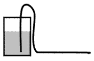
Fig. 1 is the schematic diagram of siphon irrigation conduit;
Fig. 2 is the sectional view of siphon irrigation conduit;
Fig. 3 is the realization schematic diagram of energy-conservation irrigation method.
Number in the figure: 1. absorbent material, 2. irrigation pipe tube wall.
Specific embodiments:
The utility model realizes that irrigation can be divided into the placement of the making of siphon irrigation conduit, siphon irrigation and finish three steps of irrigation.
As shown in Figure 1, 2, an end of pipeline is that diversion end, the other end are held for irrigating, and comprises the pipeline filler in pipeline, and the pipeline filler is an absorbent material; Diversion end pipeline adopts the pvc water pipe, and the tube wall of irrigating the end pipeline adopts the infiltration tube wall.
Absorbent material adopts can realize siphonage generation high hygroscopicity fibre, can select anticorrosion sponge or other organic water-absorbing materials for use, to achieve the goal.
Siphon piping is divided into conduit pipe and irrigation conduit, be that diversion is partly finished diversion and gone into the field, irrigating part finishes by permeating the feature realization irrigation of tube wall, fill the high-hydroscopicity absorbent material in this siphon piping, the diversion end of siphon irrigation conduit is placed pipeline, after the other end places the soil root, because the effect of difference in height can realize not having the external force diversion and go into the field.
As shown in Figure 3, only need when pipeline is placed an end is positioned in the water intaking pond, the other end is embedded in the root of crops in the soil, and requiring has one section difference in height to get final product;
Irrigation method as shown in Figure 3, can realize by the control of irrigating, be about to water filling in the tank, because the effect of difference in height, the height according to the water yield control tank of required irrigation has water in the tank, irrigate beginning, water exhausts in the tank, irrigates and finishes, and can realize that promptly not having the external force diversion goes into the field.
Claims (3)
1. siphon irrigation conduit, an end of described pipeline be diversion end, the other end for irrigating end, it is characterized in that: comprise the pipeline filler in pipeline, described pipeline filler is an absorbent material; Described diversion end pipeline adopts the pvc water pipe, and the tube wall of irrigating the end pipeline adopts the infiltration tube wall.
2. siphon irrigation conduit according to claim 1 is characterized in that: described absorbent material adopts the high hygroscopicity fibre that can realize that siphonage takes place.
3. siphon irrigation conduit according to claim 2 is characterized in that: described high hygroscopicity fibre adopts anticorrosion sponge.
Priority Applications (1)
| Application Number | Priority Date | Filing Date | Title |
|---|---|---|---|
| CN2011201085704U CN201957530U (en) | 2011-04-14 | 2011-04-14 | Siphon irrigation pipe |
Applications Claiming Priority (1)
| Application Number | Priority Date | Filing Date | Title |
|---|---|---|---|
| CN2011201085704U CN201957530U (en) | 2011-04-14 | 2011-04-14 | Siphon irrigation pipe |
Publications (1)
| Publication Number | Publication Date |
|---|---|
| CN201957530U true CN201957530U (en) | 2011-09-07 |
Family
ID=44520045
Family Applications (1)
| Application Number | Title | Priority Date | Filing Date |
|---|---|---|---|
| CN2011201085704U Expired - Fee Related CN201957530U (en) | 2011-04-14 | 2011-04-14 | Siphon irrigation pipe |
Country Status (1)
| Country | Link |
|---|---|
| CN (1) | CN201957530U (en) |
Cited By (6)
| Publication number | Priority date | Publication date | Assignee | Title |
|---|---|---|---|---|
| CN102726274A (en) * | 2011-04-14 | 2012-10-17 | 南京邮电大学 | Siphon irrigation pipeline and crop energy-saving irrigation method based on same |
| CN104259197A (en) * | 2014-08-26 | 2015-01-07 | 中国海洋大学 | Soil pollution repairing condition regulating device |
| CN104542187A (en) * | 2015-02-03 | 2015-04-29 | 朱晓义 | Irrigation equipment |
| CN105766567A (en) * | 2016-04-07 | 2016-07-20 | 邓洋 | Pressure-free irrigation device |
| CN106034994A (en) * | 2016-07-26 | 2016-10-26 | 大禹节水(天津)有限公司 | Ground embedded combination irrigation conduit |
| CN107082403A (en) * | 2017-06-20 | 2017-08-22 | 南京信息职业技术学院 | Unpowered liquid slow conveying device |
-
2011
- 2011-04-14 CN CN2011201085704U patent/CN201957530U/en not_active Expired - Fee Related
Cited By (7)
| Publication number | Priority date | Publication date | Assignee | Title |
|---|---|---|---|---|
| CN102726274A (en) * | 2011-04-14 | 2012-10-17 | 南京邮电大学 | Siphon irrigation pipeline and crop energy-saving irrigation method based on same |
| CN104259197A (en) * | 2014-08-26 | 2015-01-07 | 中国海洋大学 | Soil pollution repairing condition regulating device |
| CN104542187A (en) * | 2015-02-03 | 2015-04-29 | 朱晓义 | Irrigation equipment |
| CN105766567A (en) * | 2016-04-07 | 2016-07-20 | 邓洋 | Pressure-free irrigation device |
| CN105766567B (en) * | 2016-04-07 | 2020-01-17 | 邓洋 | Non-pressure irrigation device |
| CN106034994A (en) * | 2016-07-26 | 2016-10-26 | 大禹节水(天津)有限公司 | Ground embedded combination irrigation conduit |
| CN107082403A (en) * | 2017-06-20 | 2017-08-22 | 南京信息职业技术学院 | Unpowered liquid slow conveying device |
Similar Documents
| Publication | Publication Date | Title |
|---|---|---|
| CN204031977U (en) | Capillary water delivery and water-saving irrigation system | |
| CN201957530U (en) | Siphon irrigation pipe | |
| CN201308029Y (en) | Mountain rain collecting and water-saving drip irrigation system | |
| CN204616612U (en) | Hillside fields water-saving spray irrigation system | |
| CN102318538A (en) | Rain collection self-pressure irrigation system for loess plateau hilly area step greenhouses | |
| CN204335481U (en) | A kind of water-saving farmland irrigation installation | |
| CN204482583U (en) | A kind of Water saving type watering arrangement | |
| CN107006281A (en) | A kind of micro- profit flowerpot of spiral | |
| CN101869045A (en) | Automatic rain-collecting water supply system for road greenbelts | |
| CN101112168A (en) | Plant filtration irrigation method | |
| CN102726274A (en) | Siphon irrigation pipeline and crop energy-saving irrigation method based on same | |
| CN203378363U (en) | Annular vertical line source irrigation device | |
| CN204796154U (en) | System for hillock district hydraulic ram lifting irrigation cassava | |
| CN204539828U (en) | One cultivates peanut under-film drip irrigation water-fertilizer integral device | |
| CN205847961U (en) | The rainwater fertilizer integration of drought and barren mountain region utilizes system | |
| CN202918806U (en) | Buried automatic water supply device for plant | |
| CN102224799A (en) | Rain collecting and irrigating device for fruit trees in hills of loess plateau | |
| CN101606478A (en) | A kind of underground drip irrigation method based on tubelet effluent | |
| CN201563456U (en) | Deep pit infiltrating irrigation device | |
| CN202127683U (en) | Serial water-saving irrigation device for planting of plurality of seedlings | |
| CN206181995U (en) | Embedded automatic irrigation system | |
| CN207665707U (en) | A kind of water-saving irrigation device | |
| CN204291929U (en) | Greening seedling shallow embedding formula irrigation and drainage facility | |
| CN202153911U (en) | Rainwater harvesting irrigation device for fruit trees in the loess plateau hill region | |
| CN201070611Y (en) | Device for irrigation |
Legal Events
| Date | Code | Title | Description |
|---|---|---|---|
| C14 | Grant of patent or utility model | ||
| GR01 | Patent grant | ||
| CF01 | Termination of patent right due to non-payment of annual fee |
Granted publication date: 20110907 Termination date: 20150414 |
|
| EXPY | Termination of patent right or utility model |