CN201746292U - Bidirectional generator set lifting device used for shelter - Google Patents
Bidirectional generator set lifting device used for shelter Download PDFInfo
- Publication number
- CN201746292U CN201746292U CN2010205010280U CN201020501028U CN201746292U CN 201746292 U CN201746292 U CN 201746292U CN 2010205010280 U CN2010205010280 U CN 2010205010280U CN 201020501028 U CN201020501028 U CN 201020501028U CN 201746292 U CN201746292 U CN 201746292U
- Authority
- CN
- China
- Prior art keywords
- guide rail
- inner guide
- shelter
- bearing
- outer guide
- Prior art date
- Legal status (The legal status is an assumption and is not a legal conclusion. Google has not performed a legal analysis and makes no representation as to the accuracy of the status listed.)
- Expired - Fee Related
Links
Images


Landscapes
- Types And Forms Of Lifts (AREA)
Abstract
本实用新型公开了一种方舱用发电机组双向起吊装置,包括外导轨、轨道、内导轨和曲柄滑块机构,外导轨设于轨道上,内导轨设于外导轨和轨道之间,曲柄滑块机构设于内导轨的两端,还包括限位轮、挡块、第一轴承、第二轴承、限位块和防回滑器,其中:限位轮设于外导轨的两侧,挡块设于外导轨的中间,第一轴承设于内导轨的上部,第二轴承设于内导轨的下部,限位块设于内导轨的中心,防回滑器设于内导轨上。本装置完全手动操作,满足方舱在野外无电情况下的使用,也节约了车载电源的损耗;双向运动改以往的滑动为滚动,操作方便省力,便于维护;利用曲柄滑块机构把吊环升高到起吊葫芦需求位置,结构紧凑,降低整车重量和成本。
The utility model discloses a two-way hoisting device for a generator set used in a shelter, which comprises an outer guide rail, a track, an inner guide rail and a crank slider mechanism. The block mechanism is set at both ends of the inner guide rail, and also includes a limit wheel, a stopper, the first bearing, a second bearing, a limit block and an anti-slip device, wherein: the limit wheel is set on both sides of the outer guide rail, and the stopper The block is arranged in the middle of the outer guide rail, the first bearing is arranged at the top of the inner guide rail, the second bearing is arranged at the bottom of the inner guide rail, the limit block is arranged at the center of the inner guide rail, and the anti-slip device is arranged on the inner guide rail. This device is completely manual operation, which meets the use of the shelter in the field without electricity, and also saves the loss of the vehicle power supply; the two-way movement is changed from the previous sliding to rolling, which is convenient to operate, labor-saving, and easy to maintain; use the crank slider mechanism to lift the lifting ring It is as high as the required position of the lifting hoist, and the structure is compact, which reduces the weight and cost of the whole vehicle.
Description
技术领域technical field
本实用新型涉及的是一种起吊装置,尤其涉及的是一种方舱用发电机组双向起吊装置。The utility model relates to a hoisting device, in particular to a two-way hoisting device for a generator set used in a shelter.
背景技术Background technique
为了保障方舱系统在运动中和野外无电情况下可靠运行,方舱供电系统需配备车载单元自带发电机组供电,车载单元自带发电机组供电系统一般根据需要配置一台或两台发电机组。两台发电机组需安装在特制的机箱内,固定在方舱前部的载车平台上。系统固定工作时,可将发电机组移到地上,减小噪音对工作人员的影响。为了便于两台发电机组装卸,需配备双向起吊装置。在野外无电的情况下一般采用手拉葫芦起吊油机,故起吊装置的吊环要根据手拉葫芦的要求与发电机组有一定的高度差。In order to ensure the reliable operation of the shelter system in motion and in the field without electricity, the shelter power supply system needs to be equipped with a vehicle-mounted unit for power supply. The vehicle-mounted unit’s own generator set power supply system is generally equipped with one or two generators according to needs. . The two generator sets need to be installed in a special case and fixed on the vehicle-carrying platform at the front of the shelter. When the system is fixed, the generator set can be moved to the ground to reduce the impact of noise on the staff. In order to facilitate the assembly and disassembly of the two generators, a two-way lifting device is required. In the case of no electricity in the field, the chain hoist is generally used to lift the oil generator, so the lifting ring of the lifting device must have a certain height difference from the generator set according to the requirements of the chain hoist.
现行大多数发电机起吊装置采用滑动方式实现内外导轨的双向运动,并且用安装过渡支架的方式把起吊装置装在手拉葫芦需要的高度。利用滑动方式实现双向运动,运动生涩、而且要经常维护,用过渡支架抬高起吊装置的结构常和方舱端部的空调等设备干涩,既占用方舱载车比较有限的安装空间,又增加整车载重和成本。Most current generator lifting devices use a sliding method to realize the two-way movement of the inner and outer guide rails, and install the lifting device at the height required by the chain hoist by installing a transition bracket. The two-way movement is realized by using the sliding method, the movement is jerky, and frequent maintenance is required. The structure of the lifting device raised by the transition bracket is often dry with the air conditioner and other equipment at the end of the shelter, which not only occupies the relatively limited installation space of the shelter, but also increases Vehicle load and cost.
实用新型内容Utility model content
实用新型目的:本实用新型的目的在于克服现有技术的不足,提供了一种方舱用发电机组双向起吊装置,该起吊装置体积小、重量轻、结构紧凑且便于使用和维护。Purpose of the utility model: The purpose of the utility model is to overcome the deficiencies of the prior art and provide a two-way hoisting device for a shelter generator set. The hoisting device is small in size, light in weight, compact in structure and easy to use and maintain.
技术方案:本实用新型是通过以下技术方案实现的,本实用新型包括外导轨、轨道、内导轨和曲柄滑块机构,外导轨设于轨道上,内导轨设于外导轨和轨道之间,曲柄滑块机构设于内导轨的两端,还包括限位轮、挡块、第一轴承、第二轴承、限位块和防回滑器,其中:限位轮设于外导轨的两侧,挡块设于外导轨的中间,第一轴承设于内导轨的上部,第二轴承设于内导轨的下部,限位块设于内导轨的中心且与挡块相咬合,防回滑器设于内导轨上。Technical solution: the utility model is realized through the following technical solutions. The utility model includes an outer guide rail, a track, an inner guide rail and a crank slider mechanism. The outer guide rail is arranged on the track, the inner guide rail is arranged between the outer guide rail and the track, and the crank The slider mechanism is set at both ends of the inner guide rail, and also includes a limit wheel, a stopper, the first bearing, the second bearing, a limit block and an anti-slip device, wherein: the limit wheel is set on both sides of the outer guide rail, The stopper is set in the middle of the outer guide rail, the first bearing is set at the upper part of the inner guide rail, the second bearing is set at the lower part of the inner guide rail, the limit block is set at the center of the inner guide rail and is engaged with the stopper, and the anti-slip device is set on the inner rail.
所述的外导轨的两端设有密封门,所述的限位轮是全封闭限位轮,使外导轨和轨道形成一个封闭的盒体,既起到内导轨收藏时左右方向的限位,又起到良好的防雨防尘效果。The two ends of the outer guide rail are provided with sealed doors, and the limit wheel is a fully enclosed limit wheel, so that the outer guide rail and the track form a closed box, which not only serves as a limit position in the left and right directions when the inner guide rail is stored , and play a good rain and dustproof effect.
所述的内导轨的末端设有便于内导轨抽拉用的把手。The end of the inner guide rail is provided with a handle for pulling the inner guide rail.
内导轨在外导轨中抽拉运动时上下左右均有轴承做运动限位,其双向运动由滑动改为滚动,操作方便省力而且便于维护。When the inner guide rail pulls and pulls in the outer guide rail, there are bearings on the upper, lower, left, and right sides to limit the movement, and its two-way motion is changed from sliding to rolling, which is convenient to operate, labor-saving and easy to maintain.
有益效果:本起吊装置完全手动操作,满足方舱在野外无电情况下的使用,也节约了车载电源的损耗;本起吊装置的双向运动改以往的滑动为滚动,操作方便省力,便于维护;本装置利用曲柄滑块机构把吊环升高到起吊葫芦需求位置,结构紧凑,节约安装空间,降低整车重量和成本;本起吊装置外导轨两端的密封门,使外导轨形成一封闭盒体,既限制了内导轨收放时的左右运动,又起到良好的防雨防尘效果;本起吊装置的内导轨和曲柄滑块机构都是由方钢管焊接而成,而且内导轨抽拉到工作状态时其重心落在发电机箱顶部,其强度和受力分配好,安全性、可靠性高。在起吊重量达600kg时,起吊时各结构件无明显变形。Beneficial effects: the lifting device is completely manually operated, which meets the use of the shelter in the field without electricity, and also saves the loss of vehicle power supply; the two-way movement of the lifting device is changed from the previous sliding to rolling, which is convenient to operate, labor-saving, and easy to maintain; This device uses the crank slider mechanism to raise the hoisting ring to the required position of the hoist. It has a compact structure, saves installation space, and reduces the weight and cost of the vehicle. The sealed doors at both ends of the outer guide rail of the lifting device make the outer guide rail form a closed box. It not only limits the left and right movement of the inner guide rail when it is retracted, but also has a good rainproof and dustproof effect; the inner guide rail and the crank slider mechanism of the lifting device are welded by square steel pipes, and the inner guide rail is drawn to work In the normal state, its center of gravity falls on the top of the generator box, its strength and force distribution are good, and its safety and reliability are high. When the lifting weight reaches 600kg, there is no obvious deformation of the structural parts during lifting.
附图说明Description of drawings
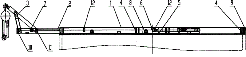
图1是本实用新型的结构示意图;Fig. 1 is the structural representation of the utility model;
图2是本实用新型收放时的主视图;Fig. 2 is the front view when the utility model is retracted;
图3是本实用新型收放时的俯视图;Fig. 3 is a top view when the utility model is folded;
图4是本实用新型收放时的左视图;Fig. 4 is the left side view when the utility model is retracted;
图5是本实用新型收放时的剖视图。Fig. 5 is a cross-sectional view of the utility model when retracted.
具体实施方式Detailed ways
下面对本实用新型的实施例作详细说明,本实施例在以本实用新型技术方案为前提下进行实施,给出了详细的实施方式和具体的操作过程,但本实用新型的保护范围不限于下述的实施例。The following is a detailed description of the embodiments of the present utility model. This embodiment is implemented on the premise of the technical solution of the present utility model, and detailed implementation methods and specific operating procedures are provided, but the protection scope of the present utility model is not limited to the following the described embodiment.
如图1所示,本实施例包括外导轨1、内导轨2、曲柄滑块机构3、全封闭限位轮4、轨道5、挡块6、第一轴承7、第二轴承8、密封门9、把手10、防回滑器11和限位块12,外导轨1设于轨道5上,内导轨2设于外导轨1和轨道5之间,曲柄滑块机构3设于内导轨2的两端,限位轮4设于外导轨1的两侧,挡块6设于外导轨1的中间,第一轴承7设于内导轨2的上部,第二轴承8设于内导轨2的下部,限位块12设于内导轨2的中心,防回滑器11设于内导轨2上,外导轨1的两端设有密封门9,内导轨2的末端设有把手10,曲柄滑块机构3位于把手10和防回滑器11之间。As shown in Figure 1, this embodiment includes an
所述的防回滑器11是销钉。Described anti-skid device 11 is a pin.
所述的内导轨2和曲柄滑块机构3由方钢管制成。The inner guide rail 2 and the slider crank mechanism 3 are made of square steel pipes.
所述的曲柄滑块机构3包括曲柄、导杆、滑块和滑道,其中:导杆通过吊环和发电机组相连,滑块位于滑道上,曲柄、导杆和滑块顺序相连。The slider crank mechanism 3 includes a crank, a guide rod, a slide block and a slideway, wherein the guide rod is connected to the generator set through a suspension ring, the slide block is located on the slideway, and the crank, guide rod and slide block are sequentially connected.
外导轨1和轨道5通过螺钉带胶固定的发电机箱顶上,当需要在发电机箱左侧起吊油机时,打开外导轨1左侧的密封门9,手扣住内导轨2左端的把手10抽拉内导轨2,当达到行程要求时,内导轨2中心右侧的限位块12和外导轨1中心的挡块6咬合,使内导轨2不能再抽拉,而且此时内导轨2的重心落在发电机箱的左侧,既保证了起吊装置起吊油机时内导轨2和外导轨1的受力平衡,又保证内导轨2不施加外力不会右滑,保证起吊油机的可靠性和稳定性,之后翻转内导轨2左端的曲柄滑块机构3,使曲柄滑块机构3的导杆端部的吊环升高到需求高度,用两个销钉锁死以防曲柄滑块机构3回滑,把发电机组的起吊葫芦挂在吊环上,垂直吊起发电机组。起吊完毕收放顺序与展开顺序相反,然后抽拉内导轨2的另一端,在油机箱的另一侧起吊油机。The
内导轨2在外导轨1中抽拉运动时上下左右均有轴承做运动限位,其双向运动改以往的滑动为滚动,操作方便省力而且便于维护。When the inner guide rail 2 pulls and pulls in the
如图2、3、4和5所示,本装置收放时内导轨2两端的曲柄滑块机构3各有3个支撑点在内导轨2上,而且曲柄滑块机构3的上表面和内导轨2的上表面平齐,保证内导轨2抽拉时运动的平稳顺畅。外导轨1两端的密封门9和外导轨1、轨道5形成一个封闭盒体,既起到内导轨2收藏时左右方向的限位,又起到良好的防雨防尘效果。本装置收放时外型尺寸:2410mm×380mm×80mm,长度方向和发电机箱一致,宽度方向远低于发电机箱,而高度仅为80mm,大大节约了油机箱顶部的空间,使得装在油机箱顶部、方舱前端部的空调、天线等设备有充裕的存放和维修空间。As shown in Figures 2, 3, 4 and 5, when the device is retracted, the slider crank mechanism 3 at both ends of the inner guide rail 2 has three supporting points on the inner guide rail 2, and the upper surface and the inner surface of the slider crank mechanism 3 The upper surface of the guide rail 2 is even, so that the movement of the inner guide rail 2 is smooth and smooth when it is drawn. The sealing
本实施例中外导轨1结构形状简单,由厚钢板折弯而成;内导轨2和曲柄滑块机构3由方钢管焊接而成,强度好、加工简单,而且内外导轨1的这种结构形式使得本装置在起吊油机时受力分布好,改以往起吊装置的点受力为面受力,油机起吊稳定可靠,安全性好。In this embodiment, the
Claims (6)
Priority Applications (1)
| Application Number | Priority Date | Filing Date | Title |
|---|---|---|---|
| CN2010205010280U CN201746292U (en) | 2010-08-23 | 2010-08-23 | Bidirectional generator set lifting device used for shelter |
Applications Claiming Priority (1)
| Application Number | Priority Date | Filing Date | Title |
|---|---|---|---|
| CN2010205010280U CN201746292U (en) | 2010-08-23 | 2010-08-23 | Bidirectional generator set lifting device used for shelter |
Publications (1)
| Publication Number | Publication Date |
|---|---|
| CN201746292U true CN201746292U (en) | 2011-02-16 |
Family
ID=43580969
Family Applications (1)
| Application Number | Title | Priority Date | Filing Date |
|---|---|---|---|
| CN2010205010280U Expired - Fee Related CN201746292U (en) | 2010-08-23 | 2010-08-23 | Bidirectional generator set lifting device used for shelter |
Country Status (1)
| Country | Link |
|---|---|
| CN (1) | CN201746292U (en) |
Cited By (1)
| Publication number | Priority date | Publication date | Assignee | Title |
|---|---|---|---|---|
| CN115123981A (en) * | 2022-06-29 | 2022-09-30 | 三一汽车制造有限公司 | Working bucket assembly and working machine |
-
2010
- 2010-08-23 CN CN2010205010280U patent/CN201746292U/en not_active Expired - Fee Related
Cited By (2)
| Publication number | Priority date | Publication date | Assignee | Title |
|---|---|---|---|---|
| CN115123981A (en) * | 2022-06-29 | 2022-09-30 | 三一汽车制造有限公司 | Working bucket assembly and working machine |
| CN115123981B (en) * | 2022-06-29 | 2023-05-23 | 三一汽车制造有限公司 | Working bucket assembly and working machine |
Similar Documents
| Publication | Publication Date | Title |
|---|---|---|
| CN106219457B (en) | A kind of bearing system and its application method | |
| CN203096920U (en) | Hardwired sludge grabbing vehicle | |
| CN211817795U (en) | Multi-mast movable lifting working platform for construction | |
| CN212251443U (en) | Special pipeline of old factory building dust removal pipeline transformation installation removes hoist device | |
| CN206427287U (en) | A kind of lifting connector arrangement of aircraft food car | |
| CN201746292U (en) | Bidirectional generator set lifting device used for shelter | |
| CN105839957B (en) | A kind of Simple stereo garage | |
| CN205061263U (en) | Lift cage | |
| CN201395492Y (en) | Stepless mechanical lifting table | |
| CN202545121U (en) | Wind generating set with crane | |
| CN206870833U (en) | A side door opening device for equipped carriage body | |
| CN201587828U (en) | Gantry crane | |
| CN201737611U (en) | Lifting device for power capacitor tower | |
| CN201985453U (en) | Circuit breaker lifting device for installation | |
| CN201342985Y (en) | Extended compartment with ceiling lifting function | |
| CN202453168U (en) | Dummy moving device | |
| CN201473254U (en) | Loading device of crane truck | |
| CN204714461U (en) | Adjustable container handling apparatus | |
| CN203065964U (en) | Quick lifting platform for bridge inspecting car | |
| CN203345968U (en) | Tower crane | |
| CN201857182U (en) | Lifting cargo elevator | |
| CN211761172U (en) | Grabbing and lifting mechanism for railway cantilever installation robot | |
| CN211396528U (en) | Auxiliary platform for electric power operation and maintenance | |
| CN202296763U (en) | Gantry crane installation structure installed on door head | |
| CN215442998U (en) | Novel dedicated construction of high floor housing construction device |
Legal Events
| Date | Code | Title | Description |
|---|---|---|---|
| C14 | Grant of patent or utility model | ||
| GR01 | Patent grant | ||
| CF01 | Termination of patent right due to non-payment of annual fee |
Granted publication date: 20110216 Termination date: 20140823 |
|
| EXPY | Termination of patent right or utility model |