CN201711820U - Shot blasting machine - Google Patents
Shot blasting machine Download PDFInfo
- Publication number
- CN201711820U CN201711820U CN2010202960559U CN201020296055U CN201711820U CN 201711820 U CN201711820 U CN 201711820U CN 2010202960559 U CN2010202960559 U CN 2010202960559U CN 201020296055 U CN201020296055 U CN 201020296055U CN 201711820 U CN201711820 U CN 201711820U
- Authority
- CN
- China
- Prior art keywords
- shot
- discharging
- blasting machine
- ball
- work holder
- Prior art date
- Legal status (The legal status is an assumption and is not a legal conclusion. Google has not performed a legal analysis and makes no representation as to the accuracy of the status listed.)
- Expired - Lifetime
Links
Images


Landscapes
- Specific Conveyance Elements (AREA)
Abstract
The utility model relates to a shot blasting machine which comprises a shot cyclic feeding device, a shot and slag separator, a dust removal device, a feeding roller table and a discharging roller table which are mutually parallel, a casing and a shot blasting chamber positioned in the casing. A work piece clamping device which has an opening with adjustable height and can rotate is arranged in the shot blasting chamber; a work piece is clamped through the work piece clamping device to perform shot blasting; and the work piece clamping device can be fixed or rotate, therefore, comprehensive and thorough shot blasting cleaning performed on the work piece can be realized. The work piece clamping device is positioned between the feeding roller table and the discharging roller table, and corresponds to the position of a shot blasting machine assembly; a delivering device corresponding to the position of the work piece clamping device is vertically arranged at the upper end of the feeding roller table; and a discharging device corresponding to the position of the work piece clamping device is vertically arranged at the upper end of the discharging roller table. The automatic charging and discharging to the work piece clamping device is realized through the delivering device and the discharging device, and the operation efficiency is effectively improved.
Description
Technical field
The utility model relates to a kind of surface of the work treating apparatus, relate in particular to a kind of shot-blasting machine.
Background technology
In casting industry, along with the high speed development of automobile industry, operation requirement raising is thereupon decored in the sand removal that motor cylinder block, cylinder cap, gearbox etc. is had the big-and-middle-sized foundry goods of complicated inner cavity.At present, generally adopt the squirrel-cage shot-blasting machine that these workpiece are carried out Shot Blasting, the squirrel-cage shot-blasting machine constantly overturns by mouse cage carrying workpiece, and the high speed bullet of dishing out by the impeller head assembly carries out removing surface to the workpiece in the mouse cage.But there is following defective in the shot-blasting machine of this structure: (1) can't realize the location cleaning: cause the inner chamber cleaning not thorough, outer surface hits excessively; (2) the anchor clamps complexity of workpiece: the foundry goods of all size size all need be equipped with corresponding mouse cage, thereby has prolonged the non-cutting time (replacing mouse cage) of equipment, has reduced the productivity ratio of equipment, has improved workman's working strength; (3) manual type is adopted in reinforced and discharging, wastes time and energy, and efficient is lower.Existing in prior technology weak point that Here it is.
Summary of the invention
The technical problems to be solved in the utility model is exactly at the existing in prior technology weak point, and provides a kind of workpiece of realizing to make an overall screening, and the higher shot-blasting machine of cleaning efficiency.
This programme is realized by following technical measures: this shot-blasting machine comprises the bullet circulating conveyor, the ball pulp separator, dust arrester, feeding roller table that is parallel to each other and discharging roller-way, housing and the shot blast room that is positioned at housing, it is adjustable to be provided with open height in the described shot blast room, and revolvable work holder, work holder is between feeding roller table and discharging roller-way, and it is corresponding with impeller head assembly position, the feeding roller table upper end is vertically installed with the pass materials device corresponding with the work holder position, and discharging roller-way upper end is vertically installed with the device for discharging corresponding with the work holder position.
Above-mentioned passing in materials device and the device for discharging moves horizontally cylinder one end and is fixedly connected with horizontal guide rail, this end of horizontal guide rail also be fixedly connected sequentially backplate group assembly and carriage.Move horizontally by moving horizontally the air cylinder driven horizontal guide rail, move horizontally, realize passing moving horizontally of materials device and device for discharging thereby drive the carriage be used to load workpiece.
The side of above-mentioned horizontal guide rail also is provided with the elevating mechanism that is slidingly connected with it.In the elevating mechanism, lifting support is slidingly connected by pulley and horizontal guide rail, and lifting support links to each other with lift cylinder on being fixed in mounting bracket by connecting rod.Lift cylinder drives horizontal guide rail, moves horizontally cylinder and carriage moves up and down by connecting rod, thereby has realized passing moving both vertically of materials device and device for discharging.
Pass materials device and discharging dress by adopting said structure, having realized passing materials device is the work holder feeding, and device for discharging is from the work holder loading and unloading material.
Above-mentioned work holder comprises clamping limb and following clamping limb, one end of last clamping limb is connected with quadric chain, the corresponding end of following clamping limb is connected with down quadric chain, be provided with the driving oil cylinder that is used to drive the two between last quadric chain and the following quadric chain, the two ends that drive oil cylinder are connected with the turning cylinder that is driven by power set by balancing pole respectively.During ball blast, can by driving clamping limb and the action of following clamping limb on the hydraulic oil cylinder driving, regulate the openings of sizes between clamping limb and the following clamping limb according to the difference of workpiece size.In the ball blast process, turning cylinder drive to be gone up clamping limb and following clamping limb rotates thereupon, thereby realizes the fixing ball blast of strengthening of rotation ball blast, fixed point swing ball blast or fixed point of workpiece, has reduced the male and female face on the workpiece, and workpiece is obtained comprehensively and Shot Blasting completely.
The feed opening end of above-mentioned discharging roller-way is provided with the upset device of falling the ball that is mated.By the upset device of falling the ball, will pour out through the remaining bullet in the workpiece behind the ball blast, make workpiece can directly enter next procedure, need not simplify operation through artificial ball.There is the conveying worm that is mated the lower end of the upset device of falling the ball, and the bullet of pouring out is delivered to the bullet circulating conveyor by conveying worm, recycles.
In the above-mentioned upset device of falling the ball, be connected with two mutually corresponding rotating disks on the bearing, between two rotating disks vertically the position of symmetry be provided with the hold-down mechanism and the roller-way of mutual correspondence, be provided with the detent mechanism that can cooperate along the rotation direction of rotating disk with rotating disk.Workpiece behind the ball blast enters on the roller-way of upset in the device of falling the ball, and after being compressed by hold-down mechanism, dial rotation drive workpiece overturns, and the remaining bullet in the workpiece is poured out.
The shot blast room upper surface that is used for fixing above-mentioned impeller head assembly is from the horizontal by angle [alpha], and the span of angle [alpha] is 10
0<α<20
0The shot blast room lower surface that is used for fixing above-mentioned impeller head assembly is from the horizontal by angle beta, and the span of angle beta is 30
0<β<38
0This structure can guarantee that bullet that the impeller head assembly is dished out can cover all surface of workpiece, can not stay the ball blast dead angle on workpiece.
In order to realize better ball blast effect, make angle [alpha]=15
0, angle beta=35
0
The beneficial effect of this programme can be learnt according to the narration to such scheme, be provided with the adjustable and revolvable work holder of open height in the shot blast room of this shot-blasting machine, work holder is between feeding roller table and discharging roller-way and corresponding with impeller head assembly position, carry out ball blast by the work holder holding workpiece, work holder can maintain static, also rotatable, thus realize workpiece is cleared up ball blast comprehensively, completely.The feeding roller table upper end is vertically installed with the pass materials device corresponding with the work holder position, discharging roller-way upper end is vertically installed with the device for discharging corresponding with the work holder position, level by passing materials device and move both vertically and be the work holder feeding, level by device for discharging and moving both vertically from work holder to the feeding of discharging roller-way, thereby realized auto feed and discharging, improved operating efficiency effectively work holder.This shot-blasting machine can be realized workpiece comprehensively, is thoroughly reached Shot Blasting efficiently.This shows that the utility model compared with prior art has substantive distinguishing features and progress, the beneficial effect of its enforcement also is conspicuous.
Description of drawings
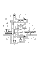
Fig. 1 looks schematic diagram for the master of the utility model specific embodiment.
Fig. 2 looks schematic diagram for the left side of the utility model specific embodiment.
Fig. 3 is the schematic top plan view of the utility model specific embodiment.
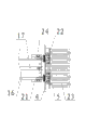
Fig. 4 is a side-looking structural representation of passing materials device.
Fig. 5 is the local schematic top plan view of passing materials device.
Fig. 6 is the structural representation of the upset device of falling the ball.
Fig. 7 is the structural representation of work holder.
Among the figure, 1 is storage bin hopper, and 2 is the ball pulp separator, 3 is the impeller head assembly, and 4 is shot blast room, and 5 is feeding roller table, 6 is housing, and 7 is conveying worm, and 8 is conveying worm, 9 are the upset device of falling the ball, and 10 are the discharging roller-way, and 11 is work holder, 12 is platform ladder railing, and 13 is bucket elevator, and 14 for passing materials device, 15 is device for discharging, and 16 is horizontal guide rail, and 17 for moving horizontally cylinder, 18 is mounting bracket, and 19 is connecting rod, and 20 is lift cylinder, 21 is lifting support, and 22 is backplate group assembly, and 23 is carriage, 24 is pulley, 25 is hold-down mechanism, and 26 is swivel joint, and 27 is roller-way, 28 is bearing, 29 is drive motors, and 30 are rotation testing agency, and 31 is rotating disk, 32 is single upper jaw, 33 is last clamping limb, and 34 is backplate group assembly, and 35 is swing roller, 36 is last quadric chain, 37 for driving oil cylinder, and 38 is driven sprocket, and 39 is turning cylinder, 40 is support, 41 is drive sprocket, and 42 is balancing pole, and 43 is motor, 44 are following quadric chain, 45 are following clamping limb, and 46 is two upper jaws, and 47 is dust arrester.
The specific embodiment
For clearly demonstrating the technical characterstic of this programme,, and, this programme is set forth in conjunction with its accompanying drawing below by the specific embodiment.
A kind of shot-blasting machine, as Fig. 1, Fig. 2 and shown in Figure 3, it comprises bullet circulating conveyor, ball pulp separator 2, dust arrester 47, the feeding roller table 5 that is parallel to each other and discharging roller-way 10, housing 6 and is positioned at the shot blast room 4 of housing 6, be provided with adjustable, and the revolvable work holder 11 of open height in the described shot blast room 4, work holder 11 is between feeding roller table 5 and discharging roller-way 10 and corresponding with impeller head assembly 3 positions.As shown in Figure 7, work holder 11 comprises clamping limb 33 and following clamping limb 45, and wherein, last clamping limb 33 is provided with single upper jaw 32 and two upper jaws 46, for example: when cleaning four cylinder bodies, employing pair upper jaws 46, but two workpiece of clamping once; When cleaning six cylinder bodies, adopt single upper jaw 32.The power intake of last clamping limb 33 is connected with quadric chain 36, the corresponding end of following clamping limb 45 is connected with down quadric chain 44, be provided with the driving oil cylinder 37 that is used to drive the two between last quadric chain 36 and the following quadric chain 44, the two ends that drive oil cylinder 37 are connected with the turning cylinder 39 that is driven by power set (motor 43) by balancing pole 42, and motor 43 drives turning cylinder 39 by the chain transmission and rotates.During ball blast, can be according to the difference of workpiece size, clamping limb 33 is gone up in oil cylinder 37 drivings and following clamping limb 45 moves by driving, and regulates the openings of sizes between clamping limb 33 and the following clamping limb 45.In the ball blast process, when turning cylinder 39 rotated, clamping limb 33 and following clamping limb 45 rotated thereupon in the drive, thereby realized the fixing ball blast of strengthening of rotation ball blast, fixed point swing ball blast or fixed point of workpiece, reduced the male and female face on the workpiece, workpiece is obtained comprehensively and Shot Blasting completely.
As shown in Figure 3, be vertically installed with corresponding with the work holder 11 positions materials device 14 of passing in feeding roller table 5 upper ends, discharging roller-way 10 upper ends are vertically installed with the device for discharging 15 corresponding with work holder 11 positions.
As shown in Figure 4 and Figure 5, in passing materials device 14 and device for discharging 15, move horizontally cylinder 17 1 ends and be fixedly connected with horizontal guide rail 16, this end of horizontal guide rail 16 also be fixedly connected sequentially backplate group assembly 22 and carriage 23, carriage 23 with pass roller in materials device 14 and the device for discharging 15 for being spaced, can easily workpiece be held up to make things convenient for carriage 23.Drive horizontal guide rails 16 and move by moving horizontally cylinder 17, horizontal guide rail 16 drives the carriage 23 that is used to carry workpiece and moves horizontally.The side of horizontal guide rail 16 also is provided with the elevating mechanism that is slidingly connected with it; In elevating mechanism, lifting support 21 is slidingly connected by pulley 24 and horizontal guide rail 16, and lifting support 21 links to each other with lift cylinder 20 on being fixed in mounting bracket 18 by connecting rod 19.Lift cylinder 20 drives horizontal guide rails 16, moves horizontally cylinder 17 and carriage 23 moves up and down by connecting rod 19.By adopting said structure, realized passing the level of materials device 14 and device for discharging 15 and moving both vertically, be work holder 11 feedings thereby realized passing materials device 14, device for discharging 15 is from work holder 11 loading and unloading materials.
As shown in Figure 3, the feed opening end of above-mentioned discharging roller-way 10 is provided with the upset device of falling the ball 9 that is mated, by the upset device of falling the ball 9, to pour out through the remaining bullet in the workpiece behind the ball blast, make workpiece can directly enter next procedure, need not simplify operation through artificial ball.
As shown in Figure 6, the upset device of falling the ball 9 comprises bearing 28, be connected with two corresponding mutually rotating disks 31 on the bearing 28, between two rotating disks 31 vertically two positions of symmetry be fixedly connected with hold-down mechanism (compressing air bag) 25 and roller-way 27 respectively, be provided with the detent mechanism that can be mated along the rotation direction of rotating disk 31.Detent mechanism is the broken line type that adopts air cylinder driven or the connecting rod of arc line type, the movable end of connecting rod can with rotating disk 31 clampings, rotating disk 31 is fixed, both throw off, rotating disk 31 is promptly rotatable.Workpiece behind the ball blast enters on the roller-way 27 of upset in the device of falling the ball 9, and after being compressed by hold-down mechanism 25, the rotating disk 31 rotating bands part of starting building overturns, and the remaining bullet in the workpiece is poured out.There is the conveying worm 8 that is mated the lower end of the upset device of falling the ball 9, the bullet of pouring out is delivered to bucket elevator 13 by conveying worm 8, by bucket elevator 13 bullet is transported to ball pulp separator 2 and carries out the separation of ball slag, clean bullet after the separation enters storage bin hopper 1, carry out once more recyclingly, dust is siphoned away by dust arrester 47.
As depicted in figs. 1 and 2, the upper surface of shot blast room 4 that is used for fixing described impeller head assembly 3 is from the horizontal by angle [alpha], and the lower surface of shot blast room 4 that is used for fixing described impeller head assembly 3 is from the horizontal by angle beta, and the span of angle [alpha] is 10
0<α<20
0, the span of angle beta is 30
0<β<38
0This structure can guarantee that bullet that impeller head assembly 3 is dished out can cover all surface of workpiece, can not stay the ball blast dead angle on workpiece.In order to realize better ball blast effect, can make angle [alpha]=15
0, angle beta=35
0
Workpiece ball blast process: the workpiece for the treatment of ball blast is transported in the shot blast room 4 by feeding roller table 5, when workpiece marches to the position corresponding with work holder 11, pass materials device 14 horizontal movement under the driving that moves horizontally cylinder 17, by carriage 23 workpiece is held up, lift cylinder 20 drivings are passed materials device 14 and are risen to setting height, move horizontally cylinder 17 driving horizontal guide rails 16 and carriage 23 then to work holder 11 horizontal movements, workpiece is delivered to work holder 11.Impeller head assembly 3 is to workpiece impelling bullet, and simultaneously, work holder 11 can be rotated the fixing ball blast of strengthening of ball blast, fixed point swing ball blast or fixed point according to ball blast needs holding workpiece.Bullet behind the ball blast falls into the conveying worm 7 that is positioned at shot blast room 4 bottoms, by conveying worm 7 bullet is transported to bucket elevator 13, bullet enters ball pulp separator 2 by bucket elevator 13, carrying out the ball slag separates, isolated bullet enters the storage bin hopper 1 at shot blast room 4 tops, enters impeller head assembly 3 by storage bin hopper 1 and recycles.
After ball blast is finished, the horizontal guide rail 16 of device for discharging 15 and carriage 23 are moved horizontally to the position of work holder 11 under the driving that moves horizontally cylinder 17, hold up workpiece by carriage 23, then, lift cylinder 20 drives whole device for discharging 15 and rises, move horizontally cylinder 17 retractions, make carriage 23 drive workpiece and move to discharging roller-way 10 tops, lift cylinder 20 drives device for discharging 15 and descends, workpiece is placed on the discharging roller-way 10, by discharging roller-way 10 with workpiece be delivered to the upset device of falling the ball 9 roller-way 27 on, by hold-down mechanism 25 with Work-sheet pressing, rotating disk 31 drives workpiece and rotates, and the remaining bullet of workpiece inside is poured out.The bullet of pouring out falls into the conveying worm 8 of the upset device of falling the ball 9 bottoms, by conveying worm 8 bullet is delivered to bucket elevator 13 in the bullet circulating conveyor, and bullet can be recycled.
Can pass through existing techniques in realizing without the technical characterictic of describing in the utility model, not repeat them here.
Claims (10)
1. shot-blasting machine, it comprises the bullet circulating conveyor, the ball pulp separator, dust arrester, feeding roller table that is parallel to each other and discharging roller-way, housing and the shot blast room that is positioned at housing, be fixed with the impeller head assembly on the shot blast room, it is characterized in that: be provided with the adjustable and revolvable work holder of open height in the described shot blast room, work holder is between feeding roller table and discharging roller-way, and it is corresponding with impeller head assembly position, the feeding roller table upper end is vertically installed with the pass materials device corresponding with the work holder position, and discharging roller-way upper end is vertically installed with the device for discharging corresponding with the work holder position.
2. shot-blasting machine according to claim 1 is characterized in that: described passing in materials device and the device for discharging moves horizontally cylinder one end and is fixedly connected with horizontal guide rail, this end of horizontal guide rail also be fixedly connected sequentially backplate group assembly and carriage.
3. shot-blasting machine according to claim 2 is characterized in that: the side of described horizontal guide rail also is provided with the elevating mechanism that is slidingly connected with it.
4. shot-blasting machine according to claim 3 is characterized in that: in the described elevating mechanism, lifting support is slidingly connected by pulley and horizontal guide rail, and lifting support links to each other with lift cylinder on being fixed in mounting bracket by connecting rod.
5. according to claim 1,2 or 3 described shot-blasting machines, it is characterized in that: described work holder comprises clamping limb and following clamping limb, one end of last clamping limb is connected with quadric chain, the corresponding end of following clamping limb is connected with down quadric chain, be provided with the driving oil cylinder that is used to drive the two between last quadric chain and the following quadric chain, the two ends that drive oil cylinder are connected with the turning cylinder that is driven by power set by balancing pole respectively.
6. shot-blasting machine according to claim 5 is characterized in that: the feed opening end of described discharging roller-way is provided with the upset device of falling the ball that is mated.
7. shot-blasting machine according to claim 6, it is characterized in that: in the described upset device of falling the ball, be connected with two corresponding mutually rotating disks on the bearing, between two rotating disks vertically the position of symmetry be provided with the hold-down mechanism and the roller-way of mutual correspondence, be provided with the detent mechanism that can be mated along the rotation direction of rotating disk.
8. shot-blasting machine according to claim 7 is characterized in that: the lower end of the described upset device of falling the ball is provided with the conveying worm that is mated.
9. according to claim 1,2 or 3 described shot-blasting machines, it is characterized in that: the shot blast room upper surface that is used for fixing described impeller head assembly is from the horizontal by angle [alpha], and the span of angle [alpha] is 10
0<α<20
0The shot blast room lower surface that is used for fixing described impeller head assembly is from the horizontal by angle beta, and the span of angle beta is 30
0<β<38
0
10. shot-blasting machine according to claim 9 is characterized in that: described angle [alpha] is 15
0, angle beta is 35
0
Priority Applications (1)
| Application Number | Priority Date | Filing Date | Title |
|---|---|---|---|
| CN2010202960559U CN201711820U (en) | 2010-08-19 | 2010-08-19 | Shot blasting machine |
Applications Claiming Priority (1)
| Application Number | Priority Date | Filing Date | Title |
|---|---|---|---|
| CN2010202960559U CN201711820U (en) | 2010-08-19 | 2010-08-19 | Shot blasting machine |
Publications (1)
| Publication Number | Publication Date |
|---|---|
| CN201711820U true CN201711820U (en) | 2011-01-19 |
Family
ID=43457817
Family Applications (1)
| Application Number | Title | Priority Date | Filing Date |
|---|---|---|---|
| CN2010202960559U Expired - Lifetime CN201711820U (en) | 2010-08-19 | 2010-08-19 | Shot blasting machine |
Country Status (1)
| Country | Link |
|---|---|
| CN (1) | CN201711820U (en) |
Cited By (5)
| Publication number | Priority date | Publication date | Assignee | Title |
|---|---|---|---|---|
| CN102975199A (en) * | 2012-12-28 | 2013-03-20 | 济南铸造锻压机械研究所有限公司 | Feeding manipulator for shot blasting machine of automobile half bridge shell |
| CN104400661A (en) * | 2014-11-28 | 2015-03-11 | 济南大学 | Shot blasting cleaning device for box body type workpiece |
| CN104400665A (en) * | 2014-11-28 | 2015-03-11 | 济南大学 | Shot blasting processing device for inner wall of box body type workpiece |
| CN107186628A (en) * | 2017-07-21 | 2017-09-22 | 中联精工(天津)有限公司 | A kind of constitutionally stable multi-faceted peener |
| CN108529158A (en) * | 2018-04-18 | 2018-09-14 | 河南科技大学 | It is a kind of can to cylinder block casting carry out ball blast, cleaning, detection roller bed conveying line |
-
2010
- 2010-08-19 CN CN2010202960559U patent/CN201711820U/en not_active Expired - Lifetime
Cited By (8)
| Publication number | Priority date | Publication date | Assignee | Title |
|---|---|---|---|---|
| CN102975199A (en) * | 2012-12-28 | 2013-03-20 | 济南铸造锻压机械研究所有限公司 | Feeding manipulator for shot blasting machine of automobile half bridge shell |
| CN104400661A (en) * | 2014-11-28 | 2015-03-11 | 济南大学 | Shot blasting cleaning device for box body type workpiece |
| CN104400665A (en) * | 2014-11-28 | 2015-03-11 | 济南大学 | Shot blasting processing device for inner wall of box body type workpiece |
| CN104400661B (en) * | 2014-11-28 | 2017-10-31 | 济南大学 | A kind of box-type workpieces wheel abrator |
| CN107186628A (en) * | 2017-07-21 | 2017-09-22 | 中联精工(天津)有限公司 | A kind of constitutionally stable multi-faceted peener |
| CN107186628B (en) * | 2017-07-21 | 2023-12-29 | 大川精工(朝阳)有限公司 | Multidirectional shot blasting device with stable structure |
| CN108529158A (en) * | 2018-04-18 | 2018-09-14 | 河南科技大学 | It is a kind of can to cylinder block casting carry out ball blast, cleaning, detection roller bed conveying line |
| CN108529158B (en) * | 2018-04-18 | 2020-05-26 | 河南科技大学 | Roller way conveying line capable of performing shot blasting, cleaning and detecting on cylinder body castings |
Similar Documents
| Publication | Publication Date | Title |
|---|---|---|
| CN201711820U (en) | Shot blasting machine | |
| CN109450193B (en) | Magnetic steel assembly machine | |
| CN204818993U (en) | Cylindrical grinder that drop feed mechanism was grabbed in area | |
| CN104400661B (en) | A kind of box-type workpieces wheel abrator | |
| CN204913635U (en) | Two -sided automatic sand blasting unit of carbide blade | |
| CN109455495B (en) | Plastic disc sheet material taking device | |
| CN104526478A (en) | Cylindrical grinding swing arm manipulator | |
| CN107414165A (en) | It is a kind of to be easy to inhale the cylinder jacket cutting equipment considered to be worth doing | |
| CN108789005A (en) | A kind of casting grid spends flash device | |
| CN104400665B (en) | Shot blasting processing device for inner wall of box body type workpiece | |
| CN110006298B (en) | Automatic decomposing line for rocket shell | |
| CN110340808A (en) | A kind of ball blast shot-peening all-in-one machine | |
| CN205009013U (en) | Polishing machine | |
| CN104589163B (en) | Automatic loading and unloading device for centerless grinding machine | |
| CN211728818U (en) | A loading attachment for crawler-type shot-blasting machine | |
| CN108527313A (en) | Bearing line grabbing device | |
| CN204353901U (en) | Peripheral milling swing arm manipulator | |
| CN107309567A (en) | A kind of welder for being used to realize reverse battery welding | |
| CN104647213A (en) | Box-type workpiece shot blasting cleaning device | |
| CN104476340B (en) | Automatic inner bore grinding device and automatic inner bore grinding method | |
| CN204339590U (en) | A kind of box-type workpieces wheel abrator | |
| CN213753424U (en) | Silica gel cover counterpoint mechanism | |
| CN104057069B (en) | A kind of automatic handling device of cast welding clamp for lead-acid storage battery and handling method thereof | |
| CN211916381U (en) | Automatic circular feeding and discharging system for disc part grinding | |
| CN211282783U (en) | Automatic feeding device for plastic workpieces |
Legal Events
| Date | Code | Title | Description |
|---|---|---|---|
| C14 | Grant of patent or utility model | ||
| GR01 | Patent grant | ||
| CX01 | Expiry of patent term | ||
| CX01 | Expiry of patent term |
Granted publication date: 20110119 |