CN201417137Y - Electromechanical type pressure dimension measuring device - Google Patents
Electromechanical type pressure dimension measuring device Download PDFInfo
- Publication number
- CN201417137Y CN201417137Y CN2009200637368U CN200920063736U CN201417137Y CN 201417137 Y CN201417137 Y CN 201417137Y CN 2009200637368 U CN2009200637368 U CN 2009200637368U CN 200920063736 U CN200920063736 U CN 200920063736U CN 201417137 Y CN201417137 Y CN 201417137Y
- Authority
- CN
- China
- Prior art keywords
- fixed
- high precision
- slide rail
- cross beam
- precision
- Prior art date
- Legal status (The legal status is an assumption and is not a legal conclusion. Google has not performed a legal analysis and makes no representation as to the accuracy of the status listed.)
- Expired - Fee Related
Links
Images


Abstract
The utility model relates to an electromechanical type pressure dimension measuring device. A base is provided and fixed with a square pipe upright post and a supporting arm, wherein the supporting arm is sleeved and fixed with the upright post and is also fixed with a measuring datum plane and a lower cross beam; both ends of a left high-precision linear slide rail and a right high-precision linear slide rail are respectively connected and fixed with an upper cross beam and the lower cross beam, and both ends of a moving cross beam are respectively fixed with own linear bearings of the left high-precision linear slide rail and the right high-precision linear slide rail; a servo motor and a speed reducer output are connected to the upper end of a high-precision ball screw, and an own flange of the high-precision ball screw is connected and fixed with the moving cross beam; the lower cross beam is also provided with a photoelectric encoder; the moving cross beam is also connected and fixed with a downward measuring compression bar and a pressure sensor; and an electric control device comprises a DSP processor, a high-precision 24 bit AD, a servo motor control system, a display system, the photoelectric encoder, a shaping circuit, the pressure sensor and a power supply system. The utility model has the advantages of advanced technique, good property, easy operation and great highmeasuring precision.
Description
Technical field:
The utility model relates to a kind of measurement mechanism, particularly relates to a kind of electromechanical pressure size measuring device.Be applicable to measurement, particularly measured product needed applied the dimensional measurement of certain pressure with certain degree of hardness product hardness.
Background technology:
Pressure size measuring is meant that the measurement products size need apply the dimensional measurement of certain pressure, at present, abroad the fields of measurement in the pressure size mainly is to adopt cylinder to produce required pressure, again according to the variation of inner pressure of air cylinder, thereby calculate the size of object being measured, this kind implementation complex structure, noise is big, precision is low, cylinder processing request height.The general employing of domestic manufacturer is manually exerted pressure, and uses the milscale manual measurement then, more original backwardness.
Summary of the invention:
Technical problem to be solved in the utility model is: solve the problem that above-mentioned prior art exists, and a kind of advanced technology, automaticity height, operation is simple and easy, measuring accuracy is high electromechanical pressure size measuring device are provided.
The technical solution adopted in the utility model is: this electromechanical pressure size measuring device is: install and fix the square tube column on base, the sway brace suit is fixed on the column, sway brace is fixedly connected with the measuring basis face, sway brace upper end support fixation sill, the two ends of left side high precision line slide rail and right high precision line slide rail are connected and fixed entablature and sill respectively, the moving beam two ends are separately fixed on the linear bearing that left high precision line slide rail and right high precision line slide rail carry, servomotor and reductor are fixed on the entablature, speed reducer output shaft is connected with high precision ball screw mandrel upper end through shaft coupling, the high precision ball screw mandrel is connected and fixed with moving beam from flanged, the high precision ball screw mandrel of sill is installed the junction and is mounted with photoelectric encoder, also is fixedly connected with down measurement depression bar and pressure transducer on the moving beam; Electric control gear comprises dsp processor, 24 AD of high precision, servo control system, display system, photoelectric encoder and shaping circuit, pressure transducer, electric power system, 24 AD are converted into digital signal with the simulating signal of pressure transducer output and are sent to DSP, DSP handles and makes comparisons with predefined force value, three tunnel pulses of photoelectric encoder output are sent to DSP behind the pulse shaping circuit, DSP controls the servomotor rotating speed and turns to, the closed loop pid algorithm is adopted in servomotor control, pid algorithm is realized by dsp processor, signal after PID regulates exports servo control system to by DSP, the servo control system output signal, the operation of control servomotor, DSP calculates to surveying the size of object in conjunction with pulse signal and the pressure sensor signal that photoelectric encoder feeds back in this process, and DSP send result of calculation to display system to show simultaneously.
Electromechanical dimension measurement method of the present utility model is:
(1), the required pressure setting of Measuring Object:
Start detection equipment, the required gaging pressure (P) of input measurement object on display panel, then on display panel by finishing key, the equipment electric control gear will write down the force value of input automatically this moment.
(2), zero adjustment:
In the pressure size measuring process, at first equipment is carried out zero adjustment, calibration steps is by down Arrow on display panel, the device measuring depression bar is operation downwards automatically, in downward operational process, when depression bar runs to the measuring basis face, equipment stops automatically, this self-braking process is to adopt the automatic feedback closed loop control of pressure to realize, thereby reaches the measurement zero adjustment;
(3), size automatic measuring process:
After zero adjustment, on display panel,, after upwards moving H1 automatically, the measurement depression bar stops 1 minute by beginning to measure key, when stopping at the H1 place, depression bar need under depression bar, place object being measured.After depression bar stops to finish, depression bar operation downwards automatically, when the detected pressure of pressure transducer equaled initial set pressure, depression bar stopped, and this moment, depression bar operation displacement was H2;
(4), object being measured size computing formula:
Object being measured is of a size of H, is H1 because the measurement depression bar upwards moves to be positioned at automatically, is H2 in the stop position displacement of operation downwards, can draw according to top data:
H=H1-H2
The utility model adopts high-precision photoelectric encoder and pressure transducer measuring technique, the microcomputerized digital treatment technology, the servomotor control-driven system, and mechanical measurement platform, intelligent, automaticity is high, simple to operate, the least displacement resolution of measurement reaches 0.000625mm, precision is high, is the equipment of a kind of advanced technology, function admirable in the pressure size measuring field.
Description of drawings:
Fig. 1 is the utility model structural representation;
Fig. 2 is the utility model electric control theory diagram;
Fig. 3 is core processor DSP;
Fig. 4 is 5V/3.3V level conversion treatment circuit figure;
Fig. 5 is a photoelectric encoder A phase pulse input shaper circuit diagram;
Fig. 6 is a photoelectric encoder B phase pulse input shaper circuit diagram;
Fig. 7 is a photoelectric encoder Z phase pulse input shaper circuit diagram;
Fig. 8 is motor speed control signal output amplifier figure;
Fig. 9 is motor steering control signal output amplifier figure;
Figure 10 is motor speed control signal output amplifier figure;
Figure 11 is 24 AD conversion processing circuit figure;
Figure 12 is the dsp processor filter capacitor, resets and clamped holding circuit
Figure 13 is external signal input connection circuit figure;
Figure 14 is control panel power module circuitry figure;
Embodiment:
Referring to accompanying drawing, electromechanical pressure size measuring device of the present utility model is: install and fix square tube column 8 on base 18, sway brace 7 suits are fixed on the column 8, sway brace 7 is fixedly connected with measuring basis face 15, sway brace 7 upper end support fixation sills 5, the two ends of left side high precision line slide rail 4 and right high precision line slide rail 13 are connected and fixed entablature 1 and sill 5 respectively, moving beam 2 two ends are separately fixed on the linear bearing that left high precision line slide rail 4 and right high precision line slide rail 13 carry, servomotor 9 and reductor 10 are fixed on the entablature 1, reductor 10 output shafts are connected with high precision ball screw mandrel 3 upper ends through shaft coupling 11, high precision ball screw mandrel 3 is connected and fixed with moving beam 2 from flanged, the high precision ball screw mandrel of sill 5 is installed the junction and is mounted with photoelectric encoder 6, also is fixedly connected with down measurement depression bar 14 and pressure transducer 12 on the moving beam 2; Electric control gear comprises dsp processor, 24 AD of high precision, servo control system, display system, photoelectric encoder and shaping circuit, pressure transducer, electric power system, 24 AD are converted into digital signal with the simulating signal of pressure transducer output and are sent to DSP, DSP handles and makes comparisons with predefined force value, three tunnel pulses of photoelectric encoder output are sent to DSP behind the pulse shaping circuit, DSP is to the servomotor rotating speed and turn to measurement, and by the closed loop pid algorithm, output signal to servo control system and display system, the operation of servo control system output control servomotor.
Electromechanical dimension measurement method of the present utility model is:
(1), the required pressure setting of Measuring Object:
Start detection equipment, the required gaging pressure (P) of input measurement object on display panel, then on display panel by finishing key, the equipment electric control gear will write down the force value of input automatically this moment;
(2), zero adjustment:
In the pressure size measuring process, at first equipment is carried out zero adjustment, calibration steps is by down Arrow on display panel, the device measuring depression bar is operation downwards automatically, in downward operational process, when depression bar runs to the measuring basis face, equipment stops automatically, this self-braking process is to adopt the automatic feedback closed loop control of pressure to realize, thereby reaches the measurement zero adjustment;
(3), size automatic measuring process:
After zero adjustment, on display panel,, after upwards moving H1 automatically, the measurement depression bar stops 1 minute by beginning to measure key, when stopping at the H1 place, depression bar need under depression bar, place object being measured.After depression bar stops to finish, depression bar operation downwards automatically, when the detected pressure of pressure transducer equaled initial set pressure, depression bar stopped, and this moment, depression bar operation displacement was H2;
(4), object being measured size computing formula:
Object being measured is of a size of H, is H1 because the measurement depression bar upwards moves to be positioned at automatically, is H2 in the stop position displacement of operation downwards, can draw according to top data:
H=H1-H2
The utility model adopts the method for two kinds of measurement sizes:
Method 1: the selective light photoelectric coder is as the dimensional measurement sensor in the utility model patent, and the photoelectric encoder that this patent is selected is the incremental encoder of 2000 pulses of every circle output.Because it is 5mm (displacement that screw mandrel whenever rotates a circle is 5mm) that mechanical hook-up is selected the screw mandrel helical pitch, screw mandrel rotates a circle and exports 2000 pulses.There are 4 edges in each slit: two passages of TMS320F2812PGFQ orthogonal coding circuit respectively have a rising edge and a negative edge, that is to say, screw mandrel whenever rotates a circle, TMS320F2812PGFQ orthogonal coding electric circuit inspection to 8000 edge, TMS320F2812PGFQ leaves detected edge number in the internal counter in.It is 0.000625mm/ that the above least displacement resolution that draws the electric control gear energy measurement is arranged
Method 2:
Can measure by method one, screw mandrel whenever rotates a circle, TMS320F2812PGFQ orthogonal coding electric circuit inspection to 8000 edge, it is 360 degree that photoelectric encoder whenever rotates a circle, the minimum angles side-play amount resolution of electric control gear energy measurement be 0.045 the degree/, because the screw mandrel helical pitch is 5mm (displacement that screw mandrel whenever rotates a circle is 5mm), so the least displacement resolution 0.000625mm (0.045 * 5/360) of electric control gear energy measurement
The device of realization electromechanical pressure size measuring provided by the utility model, this measurement mechanism ingredient has: kinematic train, measurement mechanical system, Measurement and Control System, display system.Wherein, remarks: kinematic train is made up of servomotor, reductor.Measuring system is made up of entablature, moving beam, high precision ball screw mandrel, high precision line slide rail, sill, photoelectric encoder, sill sway brace, shaft coupling, reductor, pressure transducer, measuring basis face, measurement depression bar, square tube column.Control system is made up of DSP disposable plates, high-precision A change-over panel, servo drive system.Display system is made up of LCD, LCD panel.Testing process is as follows:
Start detection equipment, the required gaging pressure of input measurement object on display panel, apparatus control system will write down the force value of input automatically.Measuring equipment control system output control command is to servo motor driving system, thereby the control servomotor rotates and produces moment of torsion, servomotor rotates the moment of torsion that produces and is delivered to reductor, transfer torque to screw mandrel through shaft coupling then, the drive moving beam is done and is pumped in the screw mandrel rotation.The direction of motion of moving beam is just being changeed counter-rotating by control system control motor and is being realized.When motor is just turning in the journey, drive moving beam and move downward, the scrambler that is fixed on the sill is gathered the displacement signal of screw mandrel rotation in real time.The measurement depression bar that is installed in simultaneously on the moving beam also moves downward with moving beam, touch object being measured until measuring head, in this process, because constantly being rotated in the forward of motor, the pressure that measuring head is applied on the object being measured constantly increases, this pressure signal is gathered in real time by being installed in the pressure transducer of measuring the depression bar top, the pressure signal that collects is converted to digital signal through the high-precision A converter and delivers to DSP, make comparisons through the DSP processing and with predefined pressure, when the power that applies is identical with pre-set pressure, the counter-rotating of DSP control motor, moving beam return, the photoelectric encoder displacement signal that while DSP will collect in real time calculate moving beam operation displacement automatically.At last, DSP will calculate the displacement of object being measured according to data that measure and displacement formula, and the displacement data with object being measured send display system to show simultaneously.
The brief introduction of electric control gear circuit:
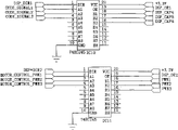
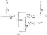
In this electric control gear circuit, Fig. 3 is the core of whole electric control gear, it is made of TMS320F2812PGFQ and necessary peripheral clock circuit, power supply, reset circuit, the shunt capacitance of TMS320F2812PGFQ chip, C10, C64, Y3 constitute clock oscillation circuit, it is the clock source of TMS320F2812PGFQ, R99, C13 provide reset signal for TMS320F2812PGFQ, and M7 is a catching diode, and all the other electric capacity are shunt capacitance among Fig. 3.External pressure sensor output differential signal amplifies by 1 pin of interface JP1,3 pin, 5 pin of 2 pin input OPA2333 again, the enlargement factor of amplifier is set to 100.8, the enlargement factor setting is to be finished by R3, R4, R5, among Figure 11, R1, R2, C2, C3, C4 constitute a wave filter, and all the other electric capacity are power filtering capacitor.Pressure sensor signal after amplifier OPA2333 amplifies is by 1 pin of OPA2333,10 pin, 11 pin that 7 pin are passed to ADS1225.ADS1225 is 24 a modulus conversion chip, and ADS1225 pin 1 is to start and stop the ADS1225 sampling, and ADS1225 pin 2 is the inputs of ADS1225 sampling clock, and ADS1225 pin 3 is the digital signal output after ADS1225 handles.1,2,3 pin of ADS1225 link to each other with 28,25,26 of TMS320F2812PGFQ respectively, and the instruction of ADS1225 controlling of sampling is by 28,25, the 26 pins output of TMS320F2812PGFQ.Because the external pressure sensor output voltage is a millivolt level signal, selects 24 ADADS1225 chips of high precision in the design, this chip sampling resolution is 0.0012mv.The A of outside input photoelectric coding, B, the Z phase pulse signal is by 4 pin of interface JP2,1 of JP3,2 pin are input to 6 of operational amplifier LM339,4,10 pin carry out signal shaping, signal after the LM339 shaping is handled is from 1 of LM339,2,13 pin output to 2 of level transferring chip IC10,3,4 pin, in Fig. 5, resistance R 71, R72 provides 2.7V threshold voltage for A phase pulse shaping circuit, in Fig. 6, resistance R 84, R85 provides 2.7V threshold voltage for B phase pulse shaping circuit, in Fig. 7, resistance R 78, R79 provides 2.7V threshold voltage for Z phase pulse shaping circuit, the Z phase signals of photoelectric encoder output is that photoelectric encoder rotates a circle, and Z exports a pulse signal mutually.IC10 mainly the pulse signal of outside input+5V be converted to the TMS320F2812PGFQ compatibility+the 3.3V pulse signal.IC10 has two control pins 1,19, and 1 pin of IC10 is a control IC10 data transfer direction, and the IC1019 pin is the pin that enables of IC10, and IC10,1,19 pin of IC10 link to each other with 101,45 pin of TMS320F2812PGFQ respectively.The IC10 direction, enable control signal and export by TMS320F2812PGFQ.After level conversion, be passed to 57,59,60 pin of TMS320F2812PGFQ orthogonal coding circuit from 18,17,16 pin of IC10 from the pulse signal of 2,3,4 pin of IC10 input.A, B phase rising edge of a pulse and the negative edge of the outside input of TMS320F2812PGFQ orthogonal coding electric circuit inspection, TMS320F2812PGFQ with the orthogonal coding electric circuit inspection to the edge number leave in the TMS320F2812PGFQ internal counter.Value in this orthogonal coding circuit count device provides accuracy guarantee for the design's displacement measurement.92 of TMS320F2812PGFQ, 93,94 pin output servomotor control signal, 92 of TMS320F2812PGFQ, 93, the control signal of 94 pin output is passed to level transferring chip IC11, IC11 is 92 of TMS320F2812PGFQ, 93, the conversion of signals of the 3.3V of 94 pin output is the 5V signal, this No. three servomotors control signal is from IC112,3,4 pin are passed to resistance R 40, R42,1 pin of R45, be passed to Q4 by resistance, Q2,1 pin of Q3, through Q4, Q2, the Q3 amplification outputs to resistance R 6, R44,1 pin of R47 is at last by resistance R 6, R44, R47 is passed to 1 of interface JP4,2,3 pin.The data transfer direction of chip IC 11 links to each other with 46,47 pin of TMS320F2812PGFQ respectively with enable signal, the data transfer direction of IC11 and enable signal steering order are by 46, the 47 pin output of TMS320F2812PGFQ, and the resistance R 40 in the circuit, R42, R45, R6, R44, R47 play metering function.The outside input supply voltage of power module is+12V, this power module for circuit provide+10 ,+5V ,+3.3V ,+working power of 1.8V.
In Fig. 1,1---entablature 2---moving beam 3---high precision ball screw mandrel
4---high accuracy line slide rail 5---sill 6---photoelectric encoders
7---sill support arm 8---square tube column 9---servomotors
10---reductor 11---shaft coupling 12---pressure sensors
13---high accuracy line slide rail 14---measurement depression bar 15---measurement datums
16---display system 17---electric control gear 18---bases
In Fig. 3, the core processor dsp chip is TMS320F2812PGFQ
In Fig. 4,5V/3.3V electrical level transferring chip IC10 and IC11 are 74HC245
In Fig. 5,6,7, the pulse shaper chip is LM339
In Fig. 8,9,10, the amplifying circuit process chip is 9013
In Figure 11,24 AD conversion process chips are ADS1225 and OPA2333
Claims (1)
1, a kind of electromechanical pressure size measuring device, it is characterized in that on base, installing and fixing the square tube column, the sway brace suit is fixed on the column, sway brace is fixedly connected with the measuring basis face, sway brace upper end support fixation sill, the two ends of left side high precision line slide rail and right high precision line slide rail are connected and fixed entablature and sill respectively, the moving beam two ends are separately fixed on the linear bearing that left high precision line slide rail and right high precision line slide rail carry, servomotor and reductor are fixed on the entablature, speed reducer output shaft is connected with high precision ball screw mandrel upper end through shaft coupling, the high precision ball screw mandrel is connected and fixed with moving beam from flanged, the high precision ball screw mandrel of sill is installed the junction and is mounted with photoelectric encoder, also is fixedly connected with down measurement depression bar and pressure transducer on the moving beam; Electric control gear comprises dsp processor, 24 AD of high precision, servo control system, display system, photoelectric encoder and shaping circuit, pressure transducer, electric power system, 24 AD are converted into digital signal with the simulating signal of pressure transducer output and are sent to DSP, DSP handles and makes comparisons with predefined force value, three tunnel pulses of photoelectric encoder output are sent to DSP behind the pulse shaping circuit, DSP is to the servomotor rotating speed and turn to measurement, and by the closed loop pid algorithm, output signal to servo control system and display system, the operation of servo control system output control servomotor.
Priority Applications (1)
| Application Number | Priority Date | Filing Date | Title |
|---|---|---|---|
| CN2009200637368U CN201417137Y (en) | 2009-03-20 | 2009-03-20 | Electromechanical type pressure dimension measuring device |
Applications Claiming Priority (1)
| Application Number | Priority Date | Filing Date | Title |
|---|---|---|---|
| CN2009200637368U CN201417137Y (en) | 2009-03-20 | 2009-03-20 | Electromechanical type pressure dimension measuring device |
Publications (1)
| Publication Number | Publication Date |
|---|---|
| CN201417137Y true CN201417137Y (en) | 2010-03-03 |
Family
ID=41793560
Family Applications (1)
| Application Number | Title | Priority Date | Filing Date |
|---|---|---|---|
| CN2009200637368U Expired - Fee Related CN201417137Y (en) | 2009-03-20 | 2009-03-20 | Electromechanical type pressure dimension measuring device |
Country Status (1)
| Country | Link |
|---|---|
| CN (1) | CN201417137Y (en) |
Cited By (7)
| Publication number | Priority date | Publication date | Assignee | Title |
|---|---|---|---|---|
| CN101839705B (en) * | 2009-03-20 | 2012-12-05 | 吕良飞 | Electromechanical pressure size measuring method and device |
| CN102818497A (en) * | 2011-05-24 | 2012-12-12 | 国网电力科学研究院 | Wave plate displacement-feed measuring device applied to vacuum laser alignment monitoring system |
| CN103389056A (en) * | 2013-08-12 | 2013-11-13 | 江苏华阳金属管件有限公司 | Straight pipe calibration device |
| CN105466374A (en) * | 2016-01-29 | 2016-04-06 | 广州翔天智能科技有限公司 | Force-controllable size measurement device and using method thereof |
| CN108021148A (en) * | 2017-12-18 | 2018-05-11 | 北京京仪敬业电工科技有限公司 | A kind of automatic line sending electric-control system of the warp of metal wire network making machine |
| CN108278984A (en) * | 2018-01-30 | 2018-07-13 | 嘉善昆腾机电设备有限公司 | A kind of aluminium section bar size detecting device and method |
| CN109900228A (en) * | 2019-03-20 | 2019-06-18 | 武汉钢铁有限公司 | A kind of gum layer of soft coal indexer |
-
2009
- 2009-03-20 CN CN2009200637368U patent/CN201417137Y/en not_active Expired - Fee Related
Cited By (9)
| Publication number | Priority date | Publication date | Assignee | Title |
|---|---|---|---|---|
| CN101839705B (en) * | 2009-03-20 | 2012-12-05 | 吕良飞 | Electromechanical pressure size measuring method and device |
| CN102818497A (en) * | 2011-05-24 | 2012-12-12 | 国网电力科学研究院 | Wave plate displacement-feed measuring device applied to vacuum laser alignment monitoring system |
| CN102818497B (en) * | 2011-05-24 | 2015-04-22 | 国网电力科学研究院 | Wave plate displacement-feed measuring device applied to vacuum laser alignment monitoring system |
| CN103389056A (en) * | 2013-08-12 | 2013-11-13 | 江苏华阳金属管件有限公司 | Straight pipe calibration device |
| CN105466374A (en) * | 2016-01-29 | 2016-04-06 | 广州翔天智能科技有限公司 | Force-controllable size measurement device and using method thereof |
| CN105466374B (en) * | 2016-01-29 | 2018-03-27 | 广州翔天智能科技有限公司 | The dimension measuring device and its application method of a kind of controllable force |
| CN108021148A (en) * | 2017-12-18 | 2018-05-11 | 北京京仪敬业电工科技有限公司 | A kind of automatic line sending electric-control system of the warp of metal wire network making machine |
| CN108278984A (en) * | 2018-01-30 | 2018-07-13 | 嘉善昆腾机电设备有限公司 | A kind of aluminium section bar size detecting device and method |
| CN109900228A (en) * | 2019-03-20 | 2019-06-18 | 武汉钢铁有限公司 | A kind of gum layer of soft coal indexer |
Similar Documents
| Publication | Publication Date | Title |
|---|---|---|
| CN101839705B (en) | Electromechanical pressure size measuring method and device | |
| CN201417137Y (en) | Electromechanical type pressure dimension measuring device | |
| CN103698126B (en) | Retarder test equipment | |
| CN103389205B (en) | A kind of device detecting combination property under ball screw assembly, stress state | |
| CN102156033B (en) | Measurement device and measurement method of torsional vibration modal of numerical control machine | |
| CN203908525U (en) | Automated calibration device for linear displacement transducer | |
| CN103630099A (en) | Automated linear displacement sensor calibration device | |
| CN103323175A (en) | Multifunctional force loading device and six-dimensional force sensor calibration method | |
| CN204007494U (en) | A kind of magnetostrictive displacement sensor Intelligent Calibration system | |
| CN102480096B (en) | Visualized intelligent precise numerically controlled crimping method and device therefor | |
| CN102589469A (en) | Device for detecting profile of planar conjugate cam and control method thereof | |
| CN203745198U (en) | Speed reducer test equipment | |
| CN105081889B (en) | A kind of application of sensor in Digit Control Machine Tool | |
| CN110398359A (en) | A kind of dynamic testing method and device of mechanical drive train composition error | |
| CN215218056U (en) | RV reduction gear capability test device based on arm | |
| CN208505235U (en) | A kind of bearing outside diameter size and taper automatic detection device | |
| CN107139193A (en) | The redundancy plane parallel mechanism control device and method of direct drive | |
| CN202010918U (en) | Measuring device for torsional vibration mode of numerical control machine | |
| CN202522218U (en) | High-precision air-pressure-type cable meter counter | |
| CN101561258B (en) | Three-dimensional body dimension automatic measuring mechanism | |
| CN102003953B (en) | Method for measuring form and position deformation of H-shape steel using measuring device | |
| CN102155907B (en) | Contact type large-diameter field measurement device and method thereof | |
| CN201434673Y (en) | Automatic measurement mechanism capable of measuring 3D body dimensions | |
| CN201127964Y (en) | Device for measuring and controlling follow-up riding wheel | |
| CN201514190U (en) | Screw-adjusted distance measurement system |
Legal Events
| Date | Code | Title | Description |
|---|---|---|---|
| C14 | Grant of patent or utility model | ||
| GR01 | Patent grant | ||
| C17 | Cessation of patent right | ||
| CF01 | Termination of patent right due to non-payment of annual fee |
Granted publication date: 20100303 Termination date: 20100320 |