CN201209316Y - Wall auto-plastering machine - Google Patents
Wall auto-plastering machine Download PDFInfo
- Publication number
- CN201209316Y CN201209316Y CNU2008200880603U CN200820088060U CN201209316Y CN 201209316 Y CN201209316 Y CN 201209316Y CN U2008200880603 U CNU2008200880603 U CN U2008200880603U CN 200820088060 U CN200820088060 U CN 200820088060U CN 201209316 Y CN201209316 Y CN 201209316Y
- Authority
- CN
- China
- Prior art keywords
- travel switch
- motor
- crane
- workbench
- electric motor
- Prior art date
- Legal status (The legal status is an assumption and is not a legal conclusion. Google has not performed a legal analysis and makes no representation as to the accuracy of the status listed.)
- Expired - Fee Related
Links
- 230000005540 biological transmission Effects 0.000 claims abstract description 12
- 230000007246 mechanism Effects 0.000 claims abstract description 11
- 239000007921 spray Substances 0.000 claims abstract description 11
- 239000003973 paint Substances 0.000 claims abstract description 5
- 238000003756 stirring Methods 0.000 claims description 6
- 238000010422 painting Methods 0.000 abstract 1
- 239000011248 coating agent Substances 0.000 description 10
- 238000000576 coating method Methods 0.000 description 10
- 238000000034 method Methods 0.000 description 9
- 238000010586 diagram Methods 0.000 description 6
- 239000000428 dust Substances 0.000 description 3
- 230000001174 ascending effect Effects 0.000 description 2
- 230000003028 elevating effect Effects 0.000 description 2
- 230000001105 regulatory effect Effects 0.000 description 2
- 208000027418 Wounds and injury Diseases 0.000 description 1
- 230000009286 beneficial effect Effects 0.000 description 1
- 238000004140 cleaning Methods 0.000 description 1
- 238000004891 communication Methods 0.000 description 1
- 230000006378 damage Effects 0.000 description 1
- 230000000994 depressogenic effect Effects 0.000 description 1
- 238000006073 displacement reaction Methods 0.000 description 1
- 230000000694 effects Effects 0.000 description 1
- 238000005516 engineering process Methods 0.000 description 1
- 208000014674 injury Diseases 0.000 description 1
- 238000009434 installation Methods 0.000 description 1
- 239000000463 material Substances 0.000 description 1
- 230000000241 respiratory effect Effects 0.000 description 1
- 210000002345 respiratory system Anatomy 0.000 description 1
- 238000005507 spraying Methods 0.000 description 1
- 239000002699 waste material Substances 0.000 description 1
Images


Landscapes
- Forklifts And Lifting Vehicles (AREA)
- Spray Control Apparatus (AREA)
Abstract
An automatic wall-painting machine comprises a spray-finishing mechanism for a worktable fixed at the top of a crane, the spray-finishing mechanism comprises a flow divider provided with a spray nozzle, a conveying pipe joins a paint bucket on the bracket, a pump on a bodywork, and the flow divider in sequence, wherein the crane is connected with a first electric motor through a first transmission mechanism, and a wheel at the bottom of the bodywork is connected with a second electric motor through a second transmission mechanism. The top of the worktable is provided with a first travel switch capable of causing the first electric motor to contrarotate, the base plate of the bodywork is provided with a second travel switch which is a double-throw switch switching between a permanent closed contact and a permanent opened contact, the permanent opened contact of the second travel switch is connected with the power cord of the second electric motor, the permanent opened contact of the second travel switch is still connected with a time-delay circuit of a time relay, and the permanent opened contact of the time relay and the permanent closed contact of the second travel switch are connected in series on the power cords of the first electric motor and the pump. The outer edge of the side of the bodywork is provided with a third travel switch capable of stopping the second electric motor.
Description
Technical field
The utility model relates to a kind of wall plastering apparatus.
Background technology
At present, along with growth in the living standard, people also improve constantly the requirement of new house. the people who buys new house before moving into new house or the seller all can be before building is sold with wall plastering, the wall that takes on a new look after whitewashing makes new house more attractive in appearance, has improved the ornamental value of new house.But because in the reality, the instrument that whitewashes lacks, whitewash backward in techniquely, manpower and materials consumption is big, and the time is long, has brought inconvenience to the work of whitewashing.
Summarize the equipment that whitewashes on the market, the general hairbrush that adopts, round brush and spray pressure type brush room machine. generally have the following disadvantages: (1) can not walk voluntarily, a position whitewash be over after, the walking of machine needs artificial carrying out, and the staff still can not leave the scene, owing to whitewash dust content height in the on-the-spot air, whitewash that the staff sucks dust in the process, respiratory system is damaged; (2) hairbrush can only use and once just need more renew, and round brush whitewashes inhomogeneous, and hand whitewashes machine, and to consume manpower big, and efficient is not high, and mostly existing automatic brush room machine is to adopt imported product, can not widespread usage; (3) can not utilize fully coating, cause unnecessary waste.
Summary of the invention
The utility model will solve the existing shortcoming that machine can not be walked automatically, the staff can not leave the scene of whitewashing, and a kind of machine that whitewashes that can walk automatically is provided.
A kind of automatic wall plastering apparatus, the spray body that comprises the workbench that is fixed on the crane top, described spray body comprises the current divider that nozzle is housed, carrier pipe connects the paint can on the support, the pump that is positioned at car body and described current divider successively, described crane connects first motor by first transmission mechanism, and the wheel of car body bottom connects second motor by second transmission mechanism; First travel switch that makes described first motor counter-rotating is equipped with on the top of described workbench, and the stroke upper end of crane is furnished with first dialing part of stirring first travel switch, and the stroke lower end of crane is furnished with second dialing part of stirring first travel switch; Second travel switch is housed on the car bottom plate, second travel switch is arranged on described workbench and drops to when minimum the position that can be touched by workbench or crane, described second travel switch is the commutator that switches between constant close contact and constant open contact, the constant open contact of described second travel switch is connected on the power line of second motor, the constant open contact of described second travel switch is the delay circuit of connect hours relay also, and the constant close contact of the constant open contact of the described time relay and described second travel switch is connected on the power line of first motor and pump; The vehicle body side outer rim is equipped with the third trip switch that second motor is stopped.
Further, described crane intersects rod members by two rows that are hinged at infall to be formed, and the rod member of bottom is connected on the polished rod guide rail on the base plate slidably by linear bearing; Be connected with cross bar between two row's crossbars, be connected with supporting plate on the cross bar of bottom, supporting plate links to each other with thread slider, and thread slider is socketed on the screw mandrel, and the gear wheel of an end of screw mandrel is meshed with the pinion of first motor output shaft.First motor output shaft rotates, and by meshed transmission gear, drives screw mandrel and rotates, and thread slider is slided up and down, and then reach the elevating movement of crane.
Coating is transported to workbench above the crane by bourdon tube, by the current divider of inside coating is shunted, and is vaporific ejection through nozzle.
Further, described second dialing part is the touch panel that is contained on the car bottom plate.
Circuit control overall process is as follows: when total power switch was connected, first motor clockwise rotated, and drove screw mandrel and rotated, crane is risen, when workbench rose to the top, room, the roof pushed first travel switch that is contained on the workbench, first motor counter-rotating (counterclockwise), crane descends, when arriving the stroke bottom, first travel switch is installed in the touch panel jack-up of car bottom plate, and first motor reverses (clockwise) once more, in the crane ascending and descending process, pump is in running order.When workbench drops to end of travel, second travel switch is stirred by crane, this moment, the time relay powered on, and picked up counting, and the described time relay is the delay working relay, in the time-delay process of the time relay, first motor and pump all are in halted state, second electric motor starting, car horizontal throw certain distance, after time-delay finishes, the time relay is started working, and its constant close contact disconnects, the constant open contact closure, second motor stops walking, first motor then begins to rotate, and the direction of rotation of first motor regulates counter-rotating by first travel switch in the previous stage, so crane rises, pump is started working, and enters next working cycles.When garage entered wall, the third trip switch of adorning by the vehicle body side outer rim cut off second motor power, and car stops walking.
The beneficial effects of the utility model are: (1) can whitewash work to the differing heights body of wall by to slide block displacement control crane lifting height.(2) can walk voluntarily, make the people reduce the injury of manual operation and dust away from operation site to human respiratory.(3) simple to operate, it is convenient to clean, and spray equipment is changed to cleaning device, can realize a tractor serves several purposes.(4) can regulate the operating rate of crane by regulating first rotating speed of motor, also can regulate spraying flow and pressure to adapt to of the requirement of different metopes by pump to different coating, adjusting is sprayed on the paint thickness of metope, reaches effect attractive in appearance and that save coating.
Description of drawings
Fig. 1 is an overall structure schematic diagram of the present utility model;
Fig. 2 is the schematic diagram of spray body of the present utility model;
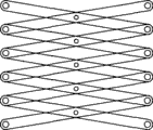
Fig. 3 is the schematic diagram of crane of the present utility model;
Fig. 4 is that the utility model driving wheel connects the vehicle body schematic diagram;
Fig. 5 is the state diagram of lifting travel lower end first travel switch and second travel switch;
Fig. 6 is a circuit diagram of the present utility model.
The specific embodiment
Below in conjunction with accompanying drawing the utility model is done further introduction:
With reference to Fig. 1-6: a kind of automatic wall plastering apparatus, the spray body that comprises the workbench 3 that is fixed on crane 2 tops, described spray body comprises the current divider 18 that nozzle 4 is housed, carrier pipe 12 is with the paint can on the support 9, the pump 10 and the current divider 18 that are positioned at car body connect successively, described crane 2 connects first motor 34 by first transmission mechanism, the wheel of car body bottom connects second motor 33 by second transmission mechanism, first travel switch 13 that makes 34 counter-rotatings of described first motor is equipped with on the top of described workbench 3, the stroke upper end of crane 2 is furnished with first dialing part of stirring first travel switch 13, the stroke lower end of crane 2 is furnished with second dialing part of stirring first travel switch 13, first dialing part is the roof in the present embodiment, and second dialing part is the touch panel 42 that is contained on the car bottom plate 1; Second travel switch 30 is housed on the car bottom plate 1, second travel switch 30 is arranged on described workbench 3 and drops to when minimum the position that can be touched by workbench 3 or crane 2, described second travel switch 30 is the commutators that switch between constant close contact and constant open contact, the constant open contact 40 of described second travel switch 30 is connected on the power line of second motor 33, the constant open contact 40 of described second travel switch 30 is the delay circuit of connect hours relay 36 also, and the constant open contact 38 of the described time relay 36 is connected on the power line of first motor 34 and pump 10 with the constant close contact 39 of described second travel switch 30; The vehicle body side outer rim is equipped with the third trip switch 31 that second motor 33 is stopped.
Described crane 2 intersects rod members by two rows that are hinged at infall to be formed, and the rod member of bottom is connected on the polished rod guide rail 23 on the base plate slidably by linear bearing 24; Be connected with cross bar 21 between two row's crossbars, be connected with supporting plate 20 on the cross bar 21 of bottom, supporting plate 20 links to each other with thread slider 19, and thread slider 19 is socketed on the screw mandrel 5, and the gear wheel 14 of an end of screw mandrel 5 is meshed with the pinion 15 of first motor, 34 output shafts.First motor, 34 output shafts rotate, and by meshed transmission gear, drive screw mandrel 5 and rotate, and thread slider 19 is slided up and down, and then reach the elevating movement of crane 2.
Coating is transported to workbench 3 above the crane 2 by bourdon tube, and the current divider 18 by inside is vaporific ejection with the coating shunting through nozzle 4.
Described wheel comprises that front-wheel 6, trailing wheel 11, the second transmission mechanisms comprise the driven sprocket 28 that is contained on the hind axle 29, is contained in the drive sprocket 27 on the output shaft of second motor 33, and drive sprocket 27 is in transmission connection by chain 16 with driven sprocket 28.
Circuit control overall process is as follows: when total power switch is connected, first motor 34 clockwise rotates, driving screw mandrel 5 rotates, crane 2 is risen, when workbench 3 rises to the top, room, the roof pushes first travel switch 13 that is contained on the workbench 3,34 counter-rotatings (counterclockwise) of first motor, crane 2 descends, when arriving the stroke bottom, first travel switch 13 is installed in touch panel 42 jack-up of car bottom plate, and first motor 34 reverses (clockwise) once more, in crane 2 ascending and descending process, pump 10 is in running order.When workbench 3 drops to end of travel, second travel switch 30 is stirred by crane 2, this moment, the time relay 36 powered on, pick up counting, the described time relay 36 is delay working relays, in the time-delay process of the time relay 36, first motor 34 and pump 10 all are in halted state, and second motor 33 starts car horizontal throw certain distance, after time-delay finishes, the time relay 36 is started working, and its constant close contact 37 disconnects constant open contact 38 closures, second motor 34 stops walking, first motor 33 then begins to rotate, and the direction of rotation of first motor 33 regulates counter-rotating by first travel switch 13 in the previous stage, so crane 2 rises, pump 10 is started working, and enters next working cycles.When garage entered wall, the third trip switch 31 by vehicle body side outer rim dress was with second motor, 34 dumps, and car stops walking.
The syndeton of circuit:
With reference to Fig. 6: behind the way circuit leading-out wire that the time relay 36 is in parallel with second motor 33, one second travel switch 30 of series connection on the live wire A that connects second motor 33, second travel switch 30 is in normally closed shelves during beginning, and second motor 33 is connected on this line, often opens a grade sky and connects.2. the joint of the time relay 36 is connected with live wire A, 7. joint is connected with zero line B, joint 3., 7. internal communication, 1. relay 36 joints 3., 4. be connected by the time-delay travel switch of relay 36 inside with joint, relay 36 is connected front connector and 4. with 1. is connected, connect back automatic jumper connection of switch behind setting-up time when time relay 36, make 3. and 1. joint connection.Second motor 33 be connected on the time relay 36 1., 2. on the joint, the time relay 36 is by internal regulation control zero line B.1. the pump 10 and first motor 34 are connected in parallel on, 2. on the joint.First travel switch 13 on the workbench is connected on first motor 34, regulates the rotating of first motor 34.4. the joint of second motor 33, pump 10 and the time relay 36 is connected by third trip switch 31, third trip switch 31 makes second motor 33 and the joint of the time relay 36 4. connect when being in normally closed grade, when third trip switch 31 is in when often opening grade, 7. the joint of circuit zero line B and second motor 33 and the time relay 36 is connected.
The circuit working principle:
When circuit general switch 35 is connected, first motor, 34 main storys, pump 10 is worked simultaneously, run into the roof when workbench 3 rises, regulate first travel switch 13, make 34 counter-rotatings of first motor, workbench 3 descends, when workbench 3 dropped to the end, first travel switch 13 was by 42 jack-up of the touch panel on the base plate, and pressing plate 41 (being fixed on the supporting plate 20) is depressed second travel switch 30 and made 13 commutations of first travel switch simultaneously, regulate 34 counter-rotatings of first motor, third trip switch 31 jumps to by pressing plate 41 and often opens shelves simultaneously, and first motor 34 and pump 10 open circuit, and quit work, the time relay 36 and second motor 33 are connected, the car level is advanced, and the time relay 36 is started working, and 3. with 1. the joint of the time relay 36 is connected behind setting-up time, first motor 34 is started working, workbench 3 is risen, and pressing plate 41 rises with supporting plate 20, and the constant close contact of third trip switch 31 is connected, pump 10 is started working, second motor 33 opens circuit, and stops to move horizontally, and enters next working cycles.
When advancing distance during less than the vehicle commander, second travel switch 30 contacts with metope to be transferred to often opens shelves, and second motor 33 is stopped, and car halts.First motor 34 is started working behind the setting-up time, enters next duty.
Claims (3)
1, a kind of automatic wall plastering apparatus, the spray body that comprises the workbench that is fixed on the crane top, described spray body comprises the current divider that nozzle is housed, carrier pipe connects the paint can on the support, the pump that is positioned at car body and described current divider successively, described crane connects first motor by first transmission mechanism, and the wheel of car body bottom connects second motor by second transmission mechanism; It is characterized in that: first travel switch that makes described first motor counter-rotating is equipped with on the top of described workbench, the stroke upper end of crane is furnished with first dialing part of stirring first travel switch, and the stroke lower end of crane is furnished with second dialing part of stirring first travel switch; Second travel switch is housed on the car bottom plate, second travel switch is arranged on described workbench and drops to when minimum the position that can be touched by workbench or crane, described second travel switch is the commutator that switches between constant close contact and constant open contact, the constant open contact of described second travel switch is connected on the power line of second motor, the constant open contact of described second travel switch is the delay circuit of connect hours relay also, and the constant close contact of the constant open contact of the described time relay and described second travel switch is connected on the power line of first motor and pump; The vehicle body side outer rim is equipped with the third trip switch that second motor is stopped.
2, automatic wall plastering apparatus as claimed in claim 2 is characterized in that: described crane intersects rod members by two rows that are hinged at infall to be formed, and the rod member of bottom is connected on the polished rod guide rail on the base plate slidably by linear bearing; Be connected with cross bar between two row's crossbars, be connected with supporting plate on the cross bar of bottom, supporting plate links to each other with thread slider, and thread slider is socketed on the screw mandrel, and the gear wheel of an end of screw mandrel is meshed with the pinion of first motor output shaft.
3, automatic wall plastering apparatus as claimed in claim 1 or 2 is characterized in that: described second dialing part is the touch panel that is contained on the car bottom plate.
Priority Applications (1)
| Application Number | Priority Date | Filing Date | Title |
|---|---|---|---|
| CNU2008200880603U CN201209316Y (en) | 2008-05-30 | 2008-05-30 | Wall auto-plastering machine |
Applications Claiming Priority (1)
| Application Number | Priority Date | Filing Date | Title |
|---|---|---|---|
| CNU2008200880603U CN201209316Y (en) | 2008-05-30 | 2008-05-30 | Wall auto-plastering machine |
Publications (1)
| Publication Number | Publication Date |
|---|---|
| CN201209316Y true CN201209316Y (en) | 2009-03-18 |
Family
ID=40480045
Family Applications (1)
| Application Number | Title | Priority Date | Filing Date |
|---|---|---|---|
| CNU2008200880603U Expired - Fee Related CN201209316Y (en) | 2008-05-30 | 2008-05-30 | Wall auto-plastering machine |
Country Status (1)
| Country | Link |
|---|---|
| CN (1) | CN201209316Y (en) |
Cited By (4)
| Publication number | Priority date | Publication date | Assignee | Title |
|---|---|---|---|---|
| CN102995887A (en) * | 2012-12-07 | 2013-03-27 | 王士豪 | Wall painting machine |
| CN104058220A (en) * | 2014-05-08 | 2014-09-24 | 浙江海洋学院 | Automatic limiting trolley |
| CN111422798A (en) * | 2020-04-09 | 2020-07-17 | 国网河北省电力有限公司 | Equipment convenient for moving transformer substation floor and using method thereof |
| CN106948587B (en) * | 2017-05-08 | 2023-11-24 | 温州市华宁建筑机械有限公司 | Conversion mechanism capable of rotating positively and negatively and wall spraying machine thereof |
-
2008
- 2008-05-30 CN CNU2008200880603U patent/CN201209316Y/en not_active Expired - Fee Related
Cited By (5)
| Publication number | Priority date | Publication date | Assignee | Title |
|---|---|---|---|---|
| CN102995887A (en) * | 2012-12-07 | 2013-03-27 | 王士豪 | Wall painting machine |
| CN104058220A (en) * | 2014-05-08 | 2014-09-24 | 浙江海洋学院 | Automatic limiting trolley |
| CN104058220B (en) * | 2014-05-08 | 2017-01-04 | 浙江海洋学院 | A kind of automatic spacing dolly |
| CN106948587B (en) * | 2017-05-08 | 2023-11-24 | 温州市华宁建筑机械有限公司 | Conversion mechanism capable of rotating positively and negatively and wall spraying machine thereof |
| CN111422798A (en) * | 2020-04-09 | 2020-07-17 | 国网河北省电力有限公司 | Equipment convenient for moving transformer substation floor and using method thereof |
Similar Documents
| Publication | Publication Date | Title |
|---|---|---|
| CN101289896B (en) | Automatic wall plastering apparatus | |
| CN201905820U (en) | Glass cleaning machine | |
| CN201209316Y (en) | Wall auto-plastering machine | |
| CN105817450A (en) | Sliding contact wire terminal automatic sweeper | |
| CN205758462U (en) | Wall cleaning plant used by a kind of finishing | |
| CN204170991U (en) | A kind of Wet-dry multifunctional cleaning machine people | |
| CN105507565A (en) | Automatic spraying machine | |
| CN207173548U (en) | Two-axis gantry full-automatic car washer | |
| CN110639865B (en) | Climbing type street lamp scrubbing robot and scrubbing method thereof | |
| CN210289022U (en) | Spraying device for spraying | |
| CN105772299A (en) | Automatic paint spraying device | |
| CN108686857B (en) | A kind of petroleum pipeline laying appearance paint spraying apparatus | |
| CN208508873U (en) | A kind of photovoltaic module Intelligent sweeping machine device people | |
| CN205268057U (en) | Ladder dust absorption formula cleaning device | |
| CN205242973U (en) | Automatic spraying machine | |
| CN209059029U (en) | A kind of curtain cleaning device | |
| CN108915219B (en) | Automatic painting device | |
| CN206424042U (en) | Full-automatic sweeping robot | |
| CN2272786Y (en) | Automatic cleaning device for high-rise building wall surface | |
| CN213790642U (en) | Dust collector for construction that work efficiency is high | |
| CN209738040U (en) | Building decoration wire way cutting equipment | |
| CN107595193A (en) | A kind of smart home cleaning glass system and its control method | |
| CN211887574U (en) | Intelligent anticorrosive material spraying system for desulfurization absorption tower of thermal power plant | |
| CN211704456U (en) | Automatic brush changing device of sweeping robot | |
| CN206659736U (en) | A kind of door and window swab |
Legal Events
| Date | Code | Title | Description |
|---|---|---|---|
| C14 | Grant of patent or utility model | ||
| GR01 | Patent grant | ||
| C17 | Cessation of patent right | ||
| CF01 | Termination of patent right due to non-payment of annual fee |
Granted publication date: 20090318 Termination date: 20100530 |