CN201155867Y - Double function air heat collector - Google Patents
Double function air heat collector Download PDFInfo
- Publication number
- CN201155867Y CN201155867Y CNU2007200604308U CN200720060430U CN201155867Y CN 201155867 Y CN201155867 Y CN 201155867Y CN U2007200604308 U CNU2007200604308 U CN U2007200604308U CN 200720060430 U CN200720060430 U CN 200720060430U CN 201155867 Y CN201155867 Y CN 201155867Y
- Authority
- CN
- China
- Prior art keywords
- pipe
- main body
- collector
- heat collector
- air heat
- Prior art date
- Legal status (The legal status is an assumption and is not a legal conclusion. Google has not performed a legal analysis and makes no representation as to the accuracy of the status listed.)
- Expired - Fee Related
Links
Images

Classifications
-
- Y—GENERAL TAGGING OF NEW TECHNOLOGICAL DEVELOPMENTS; GENERAL TAGGING OF CROSS-SECTIONAL TECHNOLOGIES SPANNING OVER SEVERAL SECTIONS OF THE IPC; TECHNICAL SUBJECTS COVERED BY FORMER USPC CROSS-REFERENCE ART COLLECTIONS [XRACs] AND DIGESTS
- Y02—TECHNOLOGIES OR APPLICATIONS FOR MITIGATION OR ADAPTATION AGAINST CLIMATE CHANGE
- Y02E—REDUCTION OF GREENHOUSE GAS [GHG] EMISSIONS, RELATED TO ENERGY GENERATION, TRANSMISSION OR DISTRIBUTION
- Y02E10/00—Energy generation through renewable energy sources
- Y02E10/40—Solar thermal energy, e.g. solar towers
- Y02E10/44—Heat exchange systems
Landscapes
- Building Environments (AREA)
Abstract
The utility model relates to the technical field of solar energy utilization, in particular to a novel double-functional air heat collector which comprises a main body, a heat absorbing board, a connecting belt, a pipe, a water collecting pipe and a glass plate; the inner end face of the main body is provided with the heat absorbing board; the heat absorbing board is provided with a plurality of fins; the fins are connected by the connecting belt and the pipe; the pipe is communicated with the water collecting pipe through a pipe end; one end of the main body is provided with an air inlet, and the other end of the main body is provided with an air outlet; one side of the main body is provided with a water collecting pipe inlet, and the other end of the main body is provided with a water collecting pipe outlet; the double-functional air heat collector can realize the double functions of room heating and hot water preparation with the solar energy, thereby improving the utilization rate of the solar energy and realizing energy saving.
Description
Technical field:
The utility model relates to technical field of solar utilization technique, refers in particular to novel double functional air heat collector.
Background technology:
The finiteness of conventional energy resource resource and the increase of environmental pressure make many in the world countries strengthen support to the new and renewable sources of energy technical development again.Solar energy is a kind of cleaning, efficiently and never depleted new forms of energy, so national governments are all with the important content of solar energy resources utilization as the national sustainable development strategy.The solar energy utilization ratio of traditional air collector is low, if it is lower to be used for the then annual solar energy utilization ratio of heating; And existing flat type solar heat collector, winter of cold district use efficient again low, shortcoming such as freeze, all can not realize room heating and produce the hot water dual-use function that can not satisfy user's dual requirements, solar energy utilization ratio is not high yet simultaneously.
The utility model content:
The purpose of this utility model is exactly to provide novel double functional air heat collector at the prior art deficiency, can realize utilizing the solar energy room heating and produce the hot water dual-use function, can improve solar energy utilization rate, energy savings.
For achieving the above object, the technical scheme that the utility model is taked is: it comprises body, absorber plate, connecting band, pipe, collector pipe, glass plate, the body inner face is provided with absorber plate, be divided on the absorber plate several fin devices are arranged, the fin device is connected and composed by connecting band and pipe, and pipe is by mouth of pipe connected set water pipe, and the two ends of body are provided with air intake and air outlet slit, the both sides of body are provided with the collector pipe inlet, the collector pipe outlet.
Described connecting band is " U " shape;
Described connecting band and pipe welding.
The beneficial effects of the utility model are: be divided on the absorber plate several fin devices are arranged, the fin device is connected and composed by connecting band and pipe, pipe is by mouth of pipe connected set water pipe, the two ends of body are provided with air intake and air outlet slit, the both sides of body are provided with the collector pipe inlet, the collector pipe outlet, the fin device has strengthened turbulent flow, has strengthened the heat transfer to air, has increased heat exchange area again, improved system effectiveness, it is simple in structure, and manufacturing and easy for installation can realize utilizing the solar energy room heating and produce the hot water dual-use function, can improve solar energy utilization rate, energy savings.
Description of drawings:
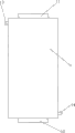
Fig. 1 is a structural representation of the present utility model;
Fig. 2 is the structural representation that the utility model removes glass plate;
Fig. 3 is the cutaway view at A-A place among Fig. 2.
The specific embodiment:
See shown in Fig. 1,2,3, the utility model comprises body 1, absorber plate 2, connecting band 3, pipe 4, collector pipe 5, glass plate 6, body 1 inner face is provided with absorber plate 2, be divided on the absorber plate 2 several fin devices 7 are arranged, fin device 7 is connected and composed by connecting band 3 and pipe 4, and pipe 4 is by mouth of pipe connected set water pipe 5, and the two ends of body 1 are provided with air intake 11 and air outlet slit 12, the both sides of body 1 are provided with collector pipe inlet 13, collector pipe outlet 14.
Described connecting band 3 is " U " shape;
Described connecting band and pipe welding.
Solar energy heat utilization principle, air dielectric flow through the fin runner and are heated, and are transported in the indoor environment through air outlet; Current flow into collector pipe 5, divide inflow pipe 4 to be heated, and flow into another root collector pipe 5 again, are transported in water heater or the heat storage water tank.
Operation principle of the present utility model is as follows:
(only adding hot-air) during heating in the winter time, inlet and outlet is opened and path of indoor room formation, and closed the intake-outlet of two collector pipes 5, from environment, send into new wind with dc fan, absorbed heat and air that temperature raises is brought into indoor at last.
When using summer, (only add hot water), inlet and outlet is closed, open the intake-outlet of two collector pipes 5 simultaneously, so heat collector and heat storage water tank constitute a path.In the circulation of water route, water flows into the pipe 4 of heat collector from water tank, and water absorbs heat and heats up, and flows into heat storage water tank at last, and domestic water is provided.
When not only having added hot-air but also having added hot water, inlet and outlet and intake-outlet are all opened, so heat collector and indoor room constitute a path, its pipe 4 also constitutes a path with heat storage water tank simultaneously.Send into new wind with dc fan, will absorb heat again and air that temperature raises is brought into indoor.In the circulation of water route, water absorbs heat and heats up, and flows into water tank.
The above embodiment, it is preferred embodiments of the present utility model, be not to limit the utility model practical range,, all should comprise in the utility model patent claim so all equivalences of doing according to the described structure of the utility model claim, feature and principle change or modify.
Claims (3)
1, novel double functional air heat collector, it comprises body (1), absorber plate (2), connecting band (3), pipe (4), collector pipe (5), glass plate (6), it is characterized in that: body (1) inner face is provided with absorber plate (2), be divided on the absorber plate (2) several fin devices (7) are arranged, fin device (7) is connected and composed by connecting band (3) and pipe (4), pipe (4) is by mouth of pipe connected set water pipe (5), the two ends of body (1) are provided with air intake (11) and air outlet slit (12), the both sides of body (1) are provided with collector pipe inlet (13), collector pipe outlet (14).
2, novel double functional air heat collector according to claim 1 is characterized in that: described connecting band (3) is " U " shape.
3, novel double functional air heat collector according to claim 1 is characterized in that: described connecting band (3) and pipe (4) welding.
Priority Applications (1)
| Application Number | Priority Date | Filing Date | Title |
|---|---|---|---|
| CNU2007200604308U CN201155867Y (en) | 2007-11-30 | 2007-11-30 | Double function air heat collector |
Applications Claiming Priority (1)
| Application Number | Priority Date | Filing Date | Title |
|---|---|---|---|
| CNU2007200604308U CN201155867Y (en) | 2007-11-30 | 2007-11-30 | Double function air heat collector |
Publications (1)
| Publication Number | Publication Date |
|---|---|
| CN201155867Y true CN201155867Y (en) | 2008-11-26 |
Family
ID=40103649
Family Applications (1)
| Application Number | Title | Priority Date | Filing Date |
|---|---|---|---|
| CNU2007200604308U Expired - Fee Related CN201155867Y (en) | 2007-11-30 | 2007-11-30 | Double function air heat collector |
Country Status (1)
| Country | Link |
|---|---|
| CN (1) | CN201155867Y (en) |
Cited By (1)
| Publication number | Priority date | Publication date | Assignee | Title |
|---|---|---|---|---|
| CN105910299A (en) * | 2014-07-17 | 2016-08-31 | 赵炜 | Solar heat collector system with height-changeable heat collecting pipe lower wall surface protrusions |
-
2007
- 2007-11-30 CN CNU2007200604308U patent/CN201155867Y/en not_active Expired - Fee Related
Cited By (2)
| Publication number | Priority date | Publication date | Assignee | Title |
|---|---|---|---|---|
| CN105910299A (en) * | 2014-07-17 | 2016-08-31 | 赵炜 | Solar heat collector system with height-changeable heat collecting pipe lower wall surface protrusions |
| CN105910299B (en) * | 2014-07-17 | 2018-01-09 | 佛山市顺德区骏日五金塑料有限公司 | A kind of solar energy collector system of thermal-collecting tube lower wall surface height of projection change |
Similar Documents
| Publication | Publication Date | Title |
|---|---|---|
| CN204574540U (en) | A kind of active solar air heat collection system combined with passive type | |
| CN103983023A (en) | Flat plate type air-water dual-purpose solar energy heat collector | |
| CN203323404U (en) | Air-water combined flat-plate solar collector | |
| CN204478580U (en) | The cold and hot combined supply system of household small-sized solar electricity | |
| CN206310741U (en) | A kind of economic benefits and social benefits plate solar heat collector with the roundabout runner of parallel fins | |
| CN204084899U (en) | A kind of plate Air-Water dual-purpose solar heat collector | |
| CN202973577U (en) | Double-effect flat plate heat collector | |
| CN201155867Y (en) | Double function air heat collector | |
| CN202056950U (en) | Novel heating device taking solar energy as heat source | |
| CN104913519B (en) | A kind of controllable heat-storage solar energy air collector being combined with building | |
| CN201407726Y (en) | Indoor water and heat supply device applying solar water heater | |
| CN201837088U (en) | Double-flow flat-plate type solar air heat collector | |
| CN203518515U (en) | Heat recovery type solar drying system | |
| CN201166468Y (en) | Plate type multifunctional solar heat collector | |
| CN201828020U (en) | Solar-air double-heat source type heat pump water heater | |
| CN102628617B (en) | Low-cost double-effect solar air collector | |
| CN202470474U (en) | Double-heat-source heat pump water heating system using air energy and solar energy | |
| CN206145980U (en) | Photovoltaic directly -heated type heat pump water heating system | |
| CN202581851U (en) | Air heat conduction type flat solar water heater | |
| CN2784823Y (en) | Split type solar water heater | |
| CN101231034A (en) | Novel double functional air heat collector | |
| CN207365429U (en) | Heat pipe type wall economic benefits and social benefits flat plate collector | |
| CN207797416U (en) | A kind of waveform plate core solar thermal collector | |
| CN207365444U (en) | Multi-functional hot pipe type solar heat collector | |
| CN201396970Y (en) | Flow channel structure of flat-plate solar collector plate core |
Legal Events
| Date | Code | Title | Description |
|---|---|---|---|
| C14 | Grant of patent or utility model | ||
| GR01 | Patent grant | ||
| C56 | Change in the name or address of the patentee | ||
| CP03 | Change of name, title or address |
Address after: Guangdong province Dongguan City Wanjiang liuyongwei Industrial Zone Guangdong Wuxing Solar Energy Ltd, zip code: 523050 Patentee after: Guangdong Fivestar Solar Energy Co., Ltd. Address before: Guangdong province Dongguan City Wanjiang liuyongwei Industrial Zone Guangdong Wuxing Solar Energy Ltd, zip code: 523050 Patentee before: Guangdong Five Star Solar Energy Co., Ltd. |
|
| CF01 | Termination of patent right due to non-payment of annual fee |
Granted publication date: 20081126 Termination date: 20141130 |
|
| EXPY | Termination of patent right or utility model |