CN1949346A - Display control apparatus, display device, and control method for a display device - Google Patents
Display control apparatus, display device, and control method for a display device Download PDFInfo
- Publication number
- CN1949346A CN1949346A CNA2006101318676A CN200610131867A CN1949346A CN 1949346 A CN1949346 A CN 1949346A CN A2006101318676 A CNA2006101318676 A CN A2006101318676A CN 200610131867 A CN200610131867 A CN 200610131867A CN 1949346 A CN1949346 A CN 1949346A
- Authority
- CN
- China
- Prior art keywords
- pulse
- zone
- transition state
- look
- control part
- Prior art date
- Legal status (The legal status is an assumption and is not a legal conclusion. Google has not performed a legal analysis and makes no representation as to the accuracy of the status listed.)
- Pending
Links
Images


Classifications
-
- G—PHYSICS
- G09—EDUCATION; CRYPTOGRAPHY; DISPLAY; ADVERTISING; SEALS
- G09G—ARRANGEMENTS OR CIRCUITS FOR CONTROL OF INDICATING DEVICES USING STATIC MEANS TO PRESENT VARIABLE INFORMATION
- G09G3/00—Control arrangements or circuits, of interest only in connection with visual indicators other than cathode-ray tubes
- G09G3/20—Control arrangements or circuits, of interest only in connection with visual indicators other than cathode-ray tubes for presentation of an assembly of a number of characters, e.g. a page, by composing the assembly by combination of individual elements arranged in a matrix no fixed position being assigned to or needed to be assigned to the individual characters or partial characters
- G09G3/34—Control arrangements or circuits, of interest only in connection with visual indicators other than cathode-ray tubes for presentation of an assembly of a number of characters, e.g. a page, by composing the assembly by combination of individual elements arranged in a matrix no fixed position being assigned to or needed to be assigned to the individual characters or partial characters by control of light from an independent source
- G09G3/3433—Control arrangements or circuits, of interest only in connection with visual indicators other than cathode-ray tubes for presentation of an assembly of a number of characters, e.g. a page, by composing the assembly by combination of individual elements arranged in a matrix no fixed position being assigned to or needed to be assigned to the individual characters or partial characters by control of light from an independent source using light modulating elements actuated by an electric field and being other than liquid crystal devices and electrochromic devices
- G09G3/344—Control arrangements or circuits, of interest only in connection with visual indicators other than cathode-ray tubes for presentation of an assembly of a number of characters, e.g. a page, by composing the assembly by combination of individual elements arranged in a matrix no fixed position being assigned to or needed to be assigned to the individual characters or partial characters by control of light from an independent source using light modulating elements actuated by an electric field and being other than liquid crystal devices and electrochromic devices based on particles moving in a fluid or in a gas, e.g. electrophoretic devices
-
- G—PHYSICS
- G04—HOROLOGY
- G04G—ELECTRONIC TIME-PIECES
- G04G9/00—Visual time or date indication means
- G04G9/08—Visual time or date indication means by building-up characters using a combination of indicating elements, e.g. by using multiplexing techniques
- G04G9/12—Visual time or date indication means by building-up characters using a combination of indicating elements, e.g. by using multiplexing techniques using light valves, e.g. liquid crystals
-
- G—PHYSICS
- G09—EDUCATION; CRYPTOGRAPHY; DISPLAY; ADVERTISING; SEALS
- G09G—ARRANGEMENTS OR CIRCUITS FOR CONTROL OF INDICATING DEVICES USING STATIC MEANS TO PRESENT VARIABLE INFORMATION
- G09G3/00—Control arrangements or circuits, of interest only in connection with visual indicators other than cathode-ray tubes
- G09G3/04—Control arrangements or circuits, of interest only in connection with visual indicators other than cathode-ray tubes for presentation of a single character by selection from a plurality of characters, or by composing the character by combination of individual elements, e.g. segments using a combination of such display devices for composing words, rows or the like, in a frame with fixed character positions
- G09G3/16—Control arrangements or circuits, of interest only in connection with visual indicators other than cathode-ray tubes for presentation of a single character by selection from a plurality of characters, or by composing the character by combination of individual elements, e.g. segments using a combination of such display devices for composing words, rows or the like, in a frame with fixed character positions by control of light from an independent source
-
- G—PHYSICS
- G09—EDUCATION; CRYPTOGRAPHY; DISPLAY; ADVERTISING; SEALS
- G09G—ARRANGEMENTS OR CIRCUITS FOR CONTROL OF INDICATING DEVICES USING STATIC MEANS TO PRESENT VARIABLE INFORMATION
- G09G2310/00—Command of the display device
- G09G2310/06—Details of flat display driving waveforms
- G09G2310/065—Waveforms comprising zero voltage phase or pause
-
- G—PHYSICS
- G09—EDUCATION; CRYPTOGRAPHY; DISPLAY; ADVERTISING; SEALS
- G09G—ARRANGEMENTS OR CIRCUITS FOR CONTROL OF INDICATING DEVICES USING STATIC MEANS TO PRESENT VARIABLE INFORMATION
- G09G2320/00—Control of display operating conditions
- G09G2320/02—Improving the quality of display appearance
-
- G—PHYSICS
- G09—EDUCATION; CRYPTOGRAPHY; DISPLAY; ADVERTISING; SEALS
- G09G—ARRANGEMENTS OR CIRCUITS FOR CONTROL OF INDICATING DEVICES USING STATIC MEANS TO PRESENT VARIABLE INFORMATION
- G09G3/00—Control arrangements or circuits, of interest only in connection with visual indicators other than cathode-ray tubes
- G09G3/20—Control arrangements or circuits, of interest only in connection with visual indicators other than cathode-ray tubes for presentation of an assembly of a number of characters, e.g. a page, by composing the assembly by combination of individual elements arranged in a matrix no fixed position being assigned to or needed to be assigned to the individual characters or partial characters
- G09G3/2007—Display of intermediate tones
- G09G3/2011—Display of intermediate tones by amplitude modulation
-
- G—PHYSICS
- G09—EDUCATION; CRYPTOGRAPHY; DISPLAY; ADVERTISING; SEALS
- G09G—ARRANGEMENTS OR CIRCUITS FOR CONTROL OF INDICATING DEVICES USING STATIC MEANS TO PRESENT VARIABLE INFORMATION
- G09G3/00—Control arrangements or circuits, of interest only in connection with visual indicators other than cathode-ray tubes
- G09G3/20—Control arrangements or circuits, of interest only in connection with visual indicators other than cathode-ray tubes for presentation of an assembly of a number of characters, e.g. a page, by composing the assembly by combination of individual elements arranged in a matrix no fixed position being assigned to or needed to be assigned to the individual characters or partial characters
- G09G3/2007—Display of intermediate tones
- G09G3/2014—Display of intermediate tones by modulation of the duration of a single pulse during which the logic level remains constant
-
- G—PHYSICS
- G09—EDUCATION; CRYPTOGRAPHY; DISPLAY; ADVERTISING; SEALS
- G09G—ARRANGEMENTS OR CIRCUITS FOR CONTROL OF INDICATING DEVICES USING STATIC MEANS TO PRESENT VARIABLE INFORMATION
- G09G3/00—Control arrangements or circuits, of interest only in connection with visual indicators other than cathode-ray tubes
- G09G3/20—Control arrangements or circuits, of interest only in connection with visual indicators other than cathode-ray tubes for presentation of an assembly of a number of characters, e.g. a page, by composing the assembly by combination of individual elements arranged in a matrix no fixed position being assigned to or needed to be assigned to the individual characters or partial characters
- G09G3/2007—Display of intermediate tones
- G09G3/2018—Display of intermediate tones by time modulation using two or more time intervals
Landscapes
- Engineering & Computer Science (AREA)
- Physics & Mathematics (AREA)
- General Physics & Mathematics (AREA)
- Computer Hardware Design (AREA)
- Theoretical Computer Science (AREA)
- Chemical & Material Sciences (AREA)
- Crystallography & Structural Chemistry (AREA)
- Electrochromic Elements, Electrophoresis, Or Variable Reflection Or Absorption Elements (AREA)
- Control Of Indicators Other Than Cathode Ray Tubes (AREA)
Abstract
A display control apparatus for controlling an electrophoretic display panel 5 having two types of electrophoretic particles of different color and polarity between electrodes has a display drive circuit 40 for supplying a pulse wave drive signal to apply a drive voltage between the electrodes to change the display color of the electrophoretic display panel to a color between the colors of the electrophoretic particles and display a gray level color, and a control unit 57 for controlling migration of the electrophoretic particles by means of the display drive circuit 40 based on the target display color, which is the display color to which the display is to be changed, and the difference in the migration characteristics of the two types of electrophoretic particles. By considering the migration characteristics of the electrophoretic particles of each color when changing the display color of the electrophoretic display panel, the discordance that can result when changing the display color is reduced.
Description
Technical field
The present invention relates to control the display control unit of electrophoretic display panel, display device and method for controlling display device with electrophoretic display panel.
Background technology
In recent years, a kind of display device with electrophoretic display panel has been proposed, this electrophoretic display panel utilized the charged particle that is scattered in the liquid by applying electric field the phenomenon of swimming, i.e. electrophoresis.This electrophoretic display panel is between electrode, for example disclosed such in the Japanese kokai publication sho 52-70791 communique, be provided with the electrophoretic layer of having enclosed white and black electrophoretic particles, by between electrode, applying the driving voltage of positive potential or negative potential, make either party in the white black electrophoresis particle towards the display surface side shifting thus, can make the demonstration look of display surface become white or black.
, known electrophoretic display panel is compressed under the situation that row switches applying same electrical when white being shown when switching to black display and black display switched to white and show, the actual switching time of needing and inequality.。
When this not only switches to the white demonstration when the white demonstration is switched to black display or black display, and underway tone when showing too, for example when showing that from white Neutral colour that (relative concentration 100%) switches to relative concentration 50% shows and when the Neutral colour that black display (relative concentration 0%) switches to relative concentration 50% shows, actually switch the asynchronism(-nization) that needs.
Therefore, for example in adjacent area (or adjacent sections),,, become the reason of bringing inharmonious sense to the user because original demonstration look causes the asynchronism(-nization) of finishing by the end of switching in that the demonstration look is become under the identical situation.
Summary of the invention
The objective of the invention is to, provide to alleviate display control unit, display device and the method for controlling display device of switching the inharmonious sense when showing look.
In order to solve above-mentioned problem, the invention provides a kind of display control unit, it is used to be controlled at the electrophoretic display panel that has the color two kind electrophoresis particles different with polarity between the electrode, it is characterized in that, this display control unit has: drive division, it can be provided for applying driving voltage between described electrode pulse type drive signal changes the demonstration look of described electrophoretic display panel between the shades of colour of described electrophoresis particle, thereby shows Neutral colour; And the transition state control part, it is the difference that target shows the migrate attribute of look and described two kinds of electrophoresis particles according to the described demonstration look as target, by the transition state of described each electrophoresis particle of described drive division control.
According to said structure, drive division is provided for applying the pulse type drive signal of driving voltage between electrode under the control of transition state control part, and the demonstration look of electrophoretic display panel is changed between the shades of colour of electrophoresis particle, thereby shows Neutral colour.
At this moment, the transition state control part is the difference that target shows the migrate attribute of look and two kinds of electrophoresis particles according to the described demonstration look as target, controls the transition state of each electrophoresis particle by drive division.
Its result when switching the demonstration look of electrophoretic display panel, can consider the control of the migrate attribute of versicolor electrophoresis particle, so can alleviate the inharmonious sense of switching when showing look.
In this case, preferred described transition state control part has the transition timing control part, when the regional transition that makes a plurality of different colours was same color, this transition timing control part began regularly by described drive division control transition, so that the transition stop timing is consistent in each zone.
According to said structure, begin regularly by adjusting transition, the transition stop timing is consistent in each zone, almost finishes simultaneously so show the look switching in whole display frame, can alleviate the inharmonious sense that shows when look switches.
And, preferred described transition state control part has pulse and applies control part, when the regional transition that makes a plurality of different colours was same color, described pulse applied control part and applies regularly by described drive division gating pulse, so that the transition stop timing is consistent in each zone.
According to said structure, apply regularly by adjusting pulse, the transition stop timing is consistent in each zone, almost finishes simultaneously so show the look switching in whole display frame, can alleviate the inharmonious sense that shows when look switches.
And, preferred described transition state control part has voltage control division, when the regional transition that makes a plurality of different colours was same color, described voltage control division was to the voltage of the described drive signal of each described area change, so that the transition stop timing is consistent in each zone.
According to said structure, by each zone being adjusted the voltage of drive signal, the transition stop timing is consistent in each zone, almost finishes simultaneously so show the look switching in whole display frame, can alleviate the inharmonious sense that shows when look switches.
And, preferred described transition state control part has the pulse width control part, when the regional transition that makes a plurality of different colours was same color, described pulse width control part was by the pulse width of described drive division controlling and driving signal, so that the transition stop timing is consistent in each zone.
According to said structure, by each zone being adjusted the pulse width of drive signal, the transition stop timing is consistent in each zone, almost finishes simultaneously so show the look switching in whole display frame, can alleviate the inharmonious sense that shows when look switches.
And, preferably has the pulse information storage list, its storage is that described target shows the umber of pulse of look needed described pulse type drive signal or based on the voltage application time of described pulse type drive signal from current demonstration colour transition, when described transition state control part switches to same color at the demonstration look with a plurality of different demonstration looks zone, with reference to the transition state of described each electrophoresis particle of described pulse information storage list control.
According to said structure, when the transition state control part switches to same color at the demonstration look with a plurality of different demonstration looks zone, with reference to the pulse information storage list, the transition state of described each electrophoresis particle of control, although it is so simple in structure, but considered the migrate attribute of versicolor electrophoresis particle, can alleviate the inharmonious sense of switching when showing look.
And, the invention provides a kind of display device, it is characterized in that this display device has: electrophoretic display panel, it has the color two kind electrophoresis particles different with polarity between electrode; Drive division, it can be provided for applying driving voltage between described electrode pulse type drive signal changes the demonstration look of described electrophoretic display panel between the shades of colour of described electrophoresis particle, thereby shows Neutral colour; And the transition state control part, it is according to the described demonstration look as target, and promptly target shows the difference of the migrate attribute of look and described two kinds of electrophoresis particles, by the transition state of described each electrophoresis particle of described drive division control.
And, in this case, preferred described transition state control part has the transition timing control part, when the regional transition that makes a plurality of different colours is same color, described transition timing control part begins regularly by described drive division control transition, so that the transition stop timing is consistent in each zone.
According to said structure, begin regularly by adjusting transition, the transition stop timing is consistent in each zone, almost finishes simultaneously so show the look switching in whole display frame, can alleviate the inharmonious sense that shows when look switches.
And, preferred described transition state control part has pulse and applies control part, when the regional transition that makes a plurality of different colours was same color, described pulse applied control part and applies regularly by described drive division gating pulse, so that the transition stop timing is consistent in each zone.
According to said structure, apply regularly by adjusting pulse, the transition stop timing is consistent in each zone, almost finishes simultaneously so show the look switching in whole display frame, can alleviate the inharmonious sense that shows when look switches.
And, preferred described transition state control part has voltage control division, when the regional transition that makes a plurality of different colours was same color, described voltage control division was to the voltage of the described drive signal of each described area change, so that the transition stop timing is consistent in each zone.
According to said structure, by each zone being adjusted the voltage of drive signal, the transition stop timing is consistent in each zone, almost finishes simultaneously so show the look switching in whole display frame, can alleviate the inharmonious sense that shows when look switches.
And, preferred described transition state control part has the pulse width control part, when the regional transition that makes a plurality of different colours was same color, described pulse width control part was by the pulse width of described drive division controlling and driving signal, so that the transition stop timing is consistent in each zone.
According to said structure, by each zone being adjusted the pulse width of drive signal, the transition stop timing is consistent in each zone, almost finishes simultaneously so show the look switching in whole display frame, can alleviate the inharmonious sense that shows when look switches.
And, preferably has the pulse information storage list, its storage is that described target shows the umber of pulse of look needed described pulse type drive signal or based on the voltage application time of described pulse type drive signal from current demonstration colour transition, described transition state control part is when showing that with a plurality of differences the demonstration look in the zone of looks switches to same color, with reference to described pulse information storage list, the transition state of described each electrophoresis particle of control.
According to said structure, the transition state control part is when showing that with a plurality of differences the demonstration look in the zone of looks switches to same color, with reference to the pulse information storage list, the transition state of described each electrophoresis particle of control, although it is so simple in structure, but considered the migrate attribute of versicolor electrophoresis particle, can alleviate the inharmonious sense of switching when showing look.
And, the invention provides a kind of display control method of display device, this display device has: the electrophoretic display panel that has the color two kind electrophoresis particles different with polarity between electrode, with the drive division that drives described electrophoretic display panel, it is characterized in that, this display control method comprises: actuation step, be provided between described electrode, applying the pulse type drive signal of driving voltage, the demonstration look of described electrophoretic display panel is changed between the shades of colour of described electrophoresis particle, thereby show Neutral colour; And the transition state controlled step, according to the described demonstration look as target, promptly target shows the difference of the migrate attribute of look and described two kinds of electrophoresis particles, by the transition state of described each electrophoresis particle of described drive division control.
According to said structure, when switching the demonstration look of electrophoretic display panel, can consider the control of the migrate attribute of versicolor electrophoresis particle, so can alleviate the inharmonious sense of switching when showing look.
And, the invention provides a kind of display control method of display device, this display device has: the electrophoretic display panel that has the color two kind electrophoresis particles different with polarity between electrode; Drive the drive division of described electrophoretic display panel; With the pulse information storage list, its storage is that described target shows the umber of pulse of look needed described pulse type drive signal or based on the voltage application time of described pulse type drive signal from current demonstration colour transition, it is characterized in that, this display control method comprises: actuation step, be provided between described electrode, applying the pulse type drive signal of driving voltage, the demonstration look of described electrophoretic display panel is changed between the shades of colour of described electrophoresis particle, thereby show Neutral colour; And transition state controlled step, with reference to described pulse information storage list, according to the described demonstration look as target, promptly target shows the difference of the migrate attribute of look and described two kinds of electrophoresis particles, by the transition state of described each electrophoresis particle of described drive division control.
According to said structure, when the transition state controlled step switches to same color at the demonstration look with a plurality of different demonstration looks zone, control the transition state of various electrophoresis particles with reference to the pulse information storage list, although it is so simple in structure, but considered the migrate attribute of versicolor electrophoresis particle, can alleviate the inharmonious sense of switching when showing look.
Description of drawings
Fig. 1 is the figure of the surface structure of the wrist-watch that relates to of expression embodiments of the present invention.
Fig. 2 is the figure that is used to illustrate the display panel of wrist-watch.
Fig. 3 is a sectional view of schematically representing the time display unit of wrist-watch.
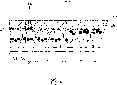
Fig. 4 is the sectional view that is used to illustrate the structure of display panel.
Fig. 5 is the block scheme of the electrical structure of express time display unit.
Fig. 6 is the figure that expression applies the relation between umber of pulse and the level.
Fig. 7 is the figure that explanation applies the relation between start time and the level transitions.
Fig. 8 is and original levels and the corresponding key diagram that applies the pulse numerical table of target level.
Fig. 9 is the figure of an example of waveform of the drive signal of expression display panel.
Embodiment
Below, with reference to description of drawings preferred implementation of the present invention.
Fig. 1 is the figure of the surface structure of the wrist-watch 1 that relates to of expression the 1st embodiment of the present invention.
As shown in Figure 1, wrist-watch 1 has watchcase 2 and is installed on this watchcase 2 and is wound on a pair of watchband 3 on the user's wrist.
Fig. 2 is the key diagram of the display panel of wrist-watch.
And, as shown in Figure 1, in each sections 5A, 5B, be respectively equipped with the background sections 5C of display background, utilize these background sections 5C, to passing through 1 shown character of each sections 5A, 5B (numeral, colon) display background.In the present embodiment, this display panel 5 uses electrophoretic display panel, will be explained below about its concrete structure.In the following description, when not needing to distinguish especially each sections 5A~5C, be expressed as sections 5X.
In watchcase 2, dispose the time display unit 10 that constitutes one with display panel 5.
Fig. 3 is the sectional view that schematically illustrates the time display unit of wrist-watch.
Shown in the sectional view of Fig. 3, the circuit pressing plate 13 that this time display unit 10 has circuit substrate 11A, display box 11B, display base plate 11C, transparency carrier 11D and keeps them.
At the upper surface of display base plate 11C, be provided with and the corresponding split electrode 14 of each sections 5A~5C, public electrode split electrode 15.
At the lower surface of this display base plate 11C, dispose circuit substrate 11A across display box 11B.The circuit component 16 that comprises the semiconductor element that constitutes display driver circuit 40 and control part 50 etc. is installed on this circuit substrate 11A.Upper surface at circuit substrate 11A is provided with the contact 11A1 that is connected with circuit component 16 (display driver circuit 40 etc.) distribution.And, be provided with the contact 11C1 that is connected with each electrode 14,15 distributions, these contacts 11A1 and 11C1 conducting by the connector 17 that runs through display box 11B at the lower surface of display base plate 11C.
In addition, be provided with switch electrode 18 in the side of circuit substrate 11A.This switch constitutes with electrode 18 can be by being located at leaf spring 19 on the circuit pressing plate 13 and conducting, when this leaf spring 19 is out of shape owing to the push of aforesaid operations button 8, and the conducting by the leaf spring 19 of this distortion.This conduction/non-conduction detects by the control part 50 that is made of circuit component 16.In addition, on the lower surface of circuit substrate 11A, be provided with the battery (power supply) 20 that driving electric is provided to circuit component 16 removably.In addition, on this circuit substrate 11A, be fixed with the circuit block 21 that covers circuit component 16, utilize this circuit block 21 holding circuit elements 16.In addition, above-mentioned battery 20 has adopted the button cell as one-shot battery, but is not limited thereto, and also can adopt secondary cell.
In transparency carrier 11D, on the one side of display base plate 11C side, be provided with the transparent common electrode 25 that is formed with ITO (Indium-Tin Oxide, tin indium oxide) by evaporation etc.Between the split electrode 14 of this transparent common electrode 25 and display base plate 11C, be provided with electrophoretic layer 30.In addition, between transparent common electrode 25 and public electrode are with split electrode 15, be inserted with public electrode with conducting parts 26.This public electrode is for example formed by conducting rubber with conducting parts 26, and this conducting rubber is out of shape with the gap between the split electrode 15 according to public electrode 25 and public electrode, thereby guarantees conducting reliably between these electrodes 25,15.
Fig. 4 is the sectional view that is used to illustrate the structure of display panel.
According to said structure, utilizing display driver circuit 40 to make public electrode shown in Figure 2 remain OV current potential (earth potential :) hereinafter referred to as " L " level with split electrode 15, public electrode 25 is the OV current potential, the split electrode 14 of regulation is under the situation of positive potential (hereinafter referred to as " H " level), produces from the electric field of split electrode 14 towards public electrode 25.Its result, the black track producing particle 34 of positively charged is to the migration of public electrode 25 sides in the micro-capsule 31, and electronegative white particle 35 moves to split electrode 14 sides.
In contrast, utilizing display driver circuit 40 to make public electrode remain positive potential (" H " level) with split electrode 15, public electrode 25 is " H " level, the split electrode 14 of regulation is under the situation of " L " level, electronegative white particle 35 is to the migration of public electrode 25 sides in the micro-capsule 31, and the black track producing particle 34 of positively charged moves to split electrode 14 sides.
Like this, display driver circuit 40 provides a public electrode 25 and each split electrode 14 to remain the drive signal of " L " level or " H " level, adjust black track producing particle 34 and white particle 35 thus to the mobile migration amount separately of the transparency carrier 11D side that can see from the outside (public electrode 25 sides), the demonstration look of the sections 5X that can see from the outside black and white between (black, white, Neutral colour) change.
And, do not produce under the state of potential difference (PD) making between public electrode 25 and the split electrode 14, can not produce the migration of electrophoresis particle (black track producing particle 34, white particle 35), keep former state (memory function) so the demonstration look constant of sections 5X.
In addition, in the present embodiment, display driver circuit 40 is built-in with booster circuit, and the voltage (for example 3V) that provides from battery 20 is boosted, the voltage of generation+12V, this+voltage or the OV voltage of 12V imposes on split electrode 14 and public electrode 25 as driving voltage.
Fig. 5 is the block scheme of the electrical structure of express time display unit.
Herein, timing circuit 51 carries out timing by the oscillating impulse of oscillatory circuit 51A is counted.This timing circuit 51 is connected with display driver circuit 40 by imput output circuit 52.
And voltage control circuit 53 will offer each several part and the display driver circuit 40 in the control part 50 from the supply electric power of battery 20.
And 57 pairs of whole time display units 10 of control circuit carry out maincenter control.This control circuit 57 constitute have CPU, the microcomputer of ROM, RAM etc., carry out the control program that is stored among the ROM by CPU, control the action of the each several part of control part 50, and export various signals to display driver circuit 40 by (I/O) 52 of input and output portion.
As mentioned above, display driver circuit 40 is the circuit that drive display panel 5.This display driver circuit 40 obtains the temporal information by timing circuit 51 timing under the indication of control circuit 57.And display driver circuit 40 provides the drive signal that applies driving voltage between above-mentioned electrode with indicated refresh interval, the demonstration look of each sections 5X of display panel 5 is changed, the current time that display panel 5 is shown as display message.
Below, the action of drawing of display panel 5 is described.
In the present embodiment, the current rank (hereinafter referred to as current rank) of drawing that control circuit 57 is worked as each sections 5X management and current demonstration form and aspect, and each sections 5X target setting is drawn rank (hereinafter referred to as the target rank), more current rank and target rank, make current rank consistent with the target rank draw processing.
Fig. 6 is that expression applies umber of pulse and draws the figure that concerns between the rank.
As shown in Figure 6, in drawing rank, white is made as relative reflectance 100%, when black is made as relative reflectance 0%, on these relative reflectances 100% and 0% these two other bases of level, also there are relative reflectance 75,50,25% these 3 ranks as medium tone, add up to have 5 ranks.
That is, in the present embodiment, the gray scale that can carry out 5 grades shows.Specifically, suitably control the white particle 35 in the micro-capsule 31 and the migration amount (migration distance) of black track producing particle 34, realize that thus gray scale shows according to relative reflectance.
In the following description, relative reflectance 100% (in vain) is expressed as rank L1, relative reflectance 75% is expressed as rank L2, relative reflectance 50% is expressed as rank L3, relative reflectance 25% is expressed as rank L4, relative reflectance 0% (deceiving) is expressed as rank L5.
In this case, even can understand that the relative reflectance difference is identical, from the higher rank (top Fig. 6) to the time of relative reflectance, than from the lower rank of relative reflectance (bottom Fig. 6) spended time more when the higher level transition than the low level transition.
Specifically, as shown in Figure 6, for example the umber of pulse that can apply is made as 0~63 pulse, original state is made as rank L1 (=white), state after the transition is made as rank L2, rank L3, rank L4, rank L5, to each level transition the time, for example applying umber of pulse needs 22,30,36,40 pulses respectively.
Relative therewith, original state is made as rank L5 (=black), when the state after the transition was made as rank L4, L3, L2, L1, for example applying umber of pulse needed 12,14,18,24 pulses respectively.
Promptly, making original state is that the adjacent area (sections) of rank L1 and rank L5 is when becoming identical Neutral colour simultaneously, when applying pulse at the same time, original state is that the zone (sections) of rank L5 reaches the target rank earlier, reach other asynchronism(-nization) of target level in each zone, so that the user feels is inharmonious.
Fig. 7 is the figure that explanation applies the relation of start time and level transition.
As shown in Figure 7, be that the zone of rank L1 (=white) and original state are the regional transition of rank L5 (=black) when being rank L3 making original state, original state is the zone spended time more of rank L1 (=white), so begin to apply pulse from time t0.
On the other hand, be the zone of rank L5 (=black) for original state, t1 applies pulse since the time, finishes transition to rank L3 simultaneously at time t2, and it is inharmonious that the user can not feel.
Fig. 8 is and initial level and the corresponding key diagram that applies the pulse numerical table of target rank.
As mentioned above, carrying out from the different rank of original state when the demonstration of same levels is switched, umber of pulse and switching time difference.
Therefore, in the present embodiment, as shown in Figure 8, be stored as table in advance switching to the required umber of pulse of target rank, carry out pulse and apply at each zone time suitable of staggering with the umber of pulse difference at each initial level.
For example, making original state is rank L1, (=white) zone and original state are rank L5, when regional transition (=black) is rank L3, for original state is rank L1, (=white) zone, switch required umber of pulse=P13, and be rank L5 for original state, (=black) zone, switch required umber of pulse=P53, (<P13), therefore for switching the required less side of umber of pulse, (be rank L5 for original state in this example, (=black) zone), make pulse apply the time that the beginning definite time delay is equivalent to umber of pulse difference Δ P
ΔP=|P53-P13|
Finish switching thus simultaneously.
Fig. 9 is the figure of an example of waveform of the drive signal of expression display panel.
In Fig. 9, the drive signal that offers public electrode 25 (driving voltage) is expressed as COM, the drive signal (driving voltage) that offers the split electrode 14 corresponding with the sections that switches to rank L1 (in vain) side from rank L5 (deceiving) side is expressed as SEG1, the drive signal (driving voltage) that offers the split electrode 14 corresponding with the sections that switches to rank L5 (deceiving) side from rank L1 (in vain) side is expressed as SEG2.Below, when not needing to distinguish drive signal SEG1, SEG2 especially, be expressed as SEG.
As shown in Figure 9, from control circuit 57 to display driver circuit 40 output show the timing (regularly M1A) of switching signals (driving data) begin till the timing that refreshes end (M1B), to be set at refresh during Ta, be set to Tb between stand-down during this refreshes outside the Ta.During this refreshes Ta be display driver circuit 40 to public electrode 25 and each split electrode 14 drive signal (driving voltage) COM, SEG are provided and switch each sections 5X demonstration look, change time showing etc. during.
And Tb shows etc. in 40 switching times of display driver circuit and afterwards shows before the switching signal that to input is next during the standby, among the Tb, display driver circuit 40 is made as energy-saving mode to its mode of operation between this stand-down between stand-down.And among the Tb, the output of output drive signal COM, the SEG of display driver circuit 40 is in high impedance status (being expressed as " HI-Z ") among the figure between stand-down.
Therefore, between stand-down, among the Tb, between public electrode 25 and each split electrode 14, can not produce potential difference (PD), so the demonstration look of each sections can maintain the color after changing among the Ta during refreshing.
During this refreshes among the Ta, in the present embodiment, parallel demonstration colour transition and the demonstration colour transition that carries out from rank L1 (in vain) side to rank L5 (deceiving) side from rank L5 (deceiving) side to rank L1 (in vain) side.Specifically, display driver circuit 40 is used to apply the drive signal SEG of the driving voltage of the corresponding voltage of the demonstration look (being white or black herein) that should show with this sections to split electrode 14 output of each sections, to public electrode 25 output voltage sequential be changed to the drive signal COM of the voltage corresponding with each demonstration look.
As this drive signal COM, in the present embodiment, the working voltage value corresponding to show switching signal (driving data) " H " level (+12V) and be the pulse signal of pulse type variation between " L " level (OV).At this moment, the pulse width W of 1 pulse of drive signal COM is set to the cycle (being 62.5ms=1/16s in this example) that can carry out frequency division to the signal from oscillatory circuit 51A output and generate, can generate the pulse signal that is equivalent to drive signal COM according to this fractional frequency signal.
In this case, apply the umber of pulse of voltage effectively to each sections 5X, adjust the gray scale of the demonstration look of each sections 5X by suitable adjustment.
Its result, during refreshing among the Ta, when the voltage of drive signal COM is " L " level, during its pulse width W, between the split electrode 14 of the sections of the drive signal SEG that has been provided " H " level and public electrode 25, produce electric field, black track producing particle 34 in the micro-capsule 31 is to the migration of public electrode 25 sides, and white particle 35 moves to split electrode 14 sides.
And the demonstration look of sections changes the amount suitable with pulse width W to rank L5 (deceiving) side.
Then, when the voltage of drive signal COM is " H " level, during its pulse width W, between the split electrode 14 of the sections of the drive signal SEG that has been provided " L " level and public electrode 25, produce electric field, white particle 35 in the micro-capsule 31 is to the migration of public electrode 25 sides, and black track producing particle 34 moves to split electrode 14 sides.
Its result, the demonstration look of sections changes the amount suitable with pulse width W to rank L1 (in vain) side.
After, equally according to the timing variations of the voltage of drive signal COM, black track producing particle 34 and white particle 35 be migration successively bit by bit between public electrode 25 and split electrode 14.Thus, the display level section of each sections ground changes, and during Ta, corresponding sections becomes same grayscale during having passed through this and refreshing.
In Fig. 9, for the pairing sections 5X of drive signal SEG2, the timing M1A that begins from the output that shows switching signal (driving data) begins to show switching.
With respect to this, for the pairing sections 5X of drive signal SEG1, play through before the 8/16s at the timing M1A that begins from the output that shows switching signal, drive signal SEG1 and drive signal COM are synchronous, so do not show switching.
And, in the moment of the timing M1A that begins from the output that shows switching signal (driving data) after pass through 8/16s, drive signal SEG1 becomes " L " level, so also begin to show switching for the sections 5X corresponding with drive signal SEG1, at the timing M1B of finishing switching, the sections 5X corresponding with drive signal SEG2 finishes switching simultaneously.
As described above,,, regularly stagger by the beginning that applies that makes pulse even apply under the different situation of umber of pulse switch showing that look needed according to present embodiment, can make switch finish regularly consistent, so can not produce inharmonious sense to the user.
Above-mentioned embodiment is a mode of the present invention after all, can be out of shape arbitrarily within the scope of the invention.
For example, in the above description, taked the demonstration look change effective impulse number according to the demonstration look before switching and after switching, and the change pulse applies beginning structure regularly, but also can take to consider to switch the area (the big more difficult more variation of area) of subject area or the retention time (long more difficult more variation of retention time) of switching preceding demonstration look, change effective impulse number and pulse and apply beginning structure regularly.
And, also can be to replace the structure that changes umber of pulse, the perhaps other structure that also changes the voltage of drive signal SEG according to the demonstration look after demonstration look before the switching and the switching.
And, also can be to replace the structure that changes umber of pulse, perhaps also change the structure of the pulse width of effective impulse in addition according to the demonstration look actual effect ground after demonstration look before the switching and the switching.
And, in the above description, taked the change pulse to apply beginning structure regularly, but also can take to reject at interval the structure of side's drive signal according to the ratio of needed effective impulse number.Specifically, be 2: 3 o'clock at the ratio of umber of pulse, can be made as the waveform identical to the waveform of drive signal SEG with drive signal COM, the ratio that makes umber of pulse is that the drive signal SEG of a side of 2 does not once apply voltage in per 3 times.
And, in the above description, with switch before rank and switch after rank corresponding, be stored as table switching needed umber of pulse, pulse applied the beginning timing be stored as table but also can constitute.
And, in the above description, example electrophoretic display panel 5 be the situation of sections mode, but be not limited thereto, also go for dot matrix way.In a word, according to the rank of the demonstration look of each unit of display (sections, point), continuously show the time, show and switch area, utilize above-mentioned gimmick to change number of drive pulses etc. and get final product.
Electrophoresis particle in the above description, the identical situation of voltage of drive signal SEG1, SEG2 has been described, but also can have constituted the voltage difference that makes drive signal SEG1, SEG2, so that can move same distance under the identical pulse number.
In this case, can constitute with switch before rank and switch after rank corresponding, switch the voltage of drive signal SEG1 or drive signal SEG2 respectively independently.
In this case, the corresponding fixed reference voltage source of quantity and voltage type can be set, or two variable reference voltage sources are set.
And, in the above description, narrated the situation that the present invention is applicable to wrist-watch, but be not limited thereto, can be widely used in the electronic equipment (display device) that has electrophoretic display panel and have the band Presentation Function of the drive unit that drives it of various clock and watch such as desk clock, wall hanging clock, wall clock, pocket-watch etc.For example, go for the electronic equipment that PDA (personal digital assistant, Personal DigitalAssistants), portable phone etc. can adopt the band Presentation Function of electrophoretic display panel.
Claims (14)
1. display control unit, it is used to be controlled at the electrophoretic display panel that has the color two kind electrophoresis particles different with polarity between the electrode, it is characterized in that, and this display control unit has:
Drive division, it can be provided for applying driving voltage between described electrode pulse type drive signal, the demonstration look that makes described electrophoretic display panel changes between the shades of colour of described electrophoresis particle and shows Neutral colour;
The transition state control part, its according to target show look, promptly as the difference of the migrate attribute of the described demonstration look of target and described two kinds of electrophoresis particles, by the transition state of described each electrophoresis particle of described drive division control.
2. display control unit according to claim 1, it is characterized in that, described transition state control part has the conversion timing control part, when it is converted to same color in the zone that makes a plurality of different colours, begin regularly by described drive division control transformation, make EOC regularly consistent in each zone.
3. display control unit according to claim 1, it is characterized in that, described transition state control part has pulse and applies control part, when it is converted to same color in the zone that makes a plurality of different colours, apply regularly by described drive division gating pulse, make EOC regularly consistent in each zone.
4. display control unit according to claim 1, it is characterized in that, described transition state control part has voltage control division, when it is converted to same color in the zone that makes a plurality of different colours, for the voltage of the described drive signal of each described area change, make EOC regularly consistent in each zone.
5. display control unit according to claim 1, it is characterized in that, described transition state control part has the pulse width control part, when it is converted to same color in the zone that makes a plurality of different colours, by the pulse width of described drive division controlling and driving signal, make EOC regularly consistent in each zone.
6. display control unit according to claim 1, it is characterized in that, this display control unit has the pulse information storage list, its storage is converted to described target from current demonstration look and shows the umber of pulse of the described pulse type drive signal that look required or the voltage application time of described pulse type drive signal
Described transition state control part is when showing that with a plurality of differences the demonstration look in the zone of looks switches to same color, with reference to the transition state of described each electrophoresis particle of described pulse information storage list control.
7. a display device is characterized in that, this display device has:
Electrophoretic display panel, it has the color two kind electrophoresis particles different with polarity between electrode;
Drive division, it can be provided for applying driving voltage between described electrode pulse type drive signal, the demonstration look that makes described electrophoretic display panel changes between the shades of colour of described electrophoresis particle and shows Neutral colour;
The transition state control part, its according to target show look, promptly as the difference of the migrate attribute of the described demonstration look of target and described two kinds of electrophoresis particles, by the transition state of described each electrophoresis particle of described drive division control.
8. display device according to claim 7, it is characterized in that, described transition state control part has the conversion timing control part, when it is converted to same color in the zone that makes a plurality of different colours, begin regularly by described drive division control transformation, make EOC regularly consistent in each zone.
9. display device according to claim 7, it is characterized in that, described transition state control part has pulse and applies control part, when it is converted to same color in the zone that makes a plurality of different colours, apply regularly by described drive division gating pulse, make EOC regularly consistent in each zone.
10. display device according to claim 7, it is characterized in that, described transition state control part has voltage control division, when it is converted to same color in the zone that makes a plurality of different colours, for the voltage of the described drive signal of each described area change, make EOC regularly consistent in each zone.
11. display device according to claim 7, it is characterized in that, described transition state control part has the pulse width control part, when it is converted to same color in the zone that makes a plurality of different colours, by the pulse width of described drive division controlling and driving signal, make EOC regularly consistent in each zone.
12. display device according to claim 7, it is characterized in that, this display device has the pulse information storage list, its storage is converted to described target from current demonstration look and shows the umber of pulse of the described pulse type drive signal that look required or the voltage application time of described pulse type drive signal
Described transition state control part is when showing that with a plurality of differences the demonstration look in the zone of looks switches to same color, with reference to the transition state of described each electrophoresis particle of described pulse information storage list control.
13. the display control method of a display device, this display device has: the electrophoretic display panel that has the color two kind electrophoresis particles different with polarity between electrode, drive division with driving described electrophoretic display panel is characterized in that this display control method may further comprise the steps:
Actuation step is provided for applying the pulse type drive signal of driving voltage between described electrode, the demonstration look that makes described electrophoretic display panel changes between the shades of colour of described electrophoresis particle and shows Neutral colour;
The transition state controlled step, according to target show look, promptly as the difference of the migrate attribute of the described demonstration look of target and described two kinds of electrophoresis particles, by the transition state of described each electrophoresis particle of described drive division control.
14. the display control method of a display device, this display device has: the electrophoretic display panel that has the color two kind electrophoresis particles different with polarity between electrode; Drive the drive division of described electrophoretic display panel; With the pulse information storage list, its storage is converted to described target from current demonstration look and shows the umber of pulse of the described pulse type drive signal that look required or the voltage application time of described pulse type drive signal, it is characterized in that this display control method may further comprise the steps:
Actuation step is provided for applying the pulse type drive signal of driving voltage between described electrode, the demonstration look that makes described electrophoretic display panel changes between the shades of colour of described electrophoresis particle and shows Neutral colour;
The transition state controlled step, with reference to described pulse information storage list, according to target show look, promptly as the difference of the migrate attribute of the described demonstration look of target and described two kinds of electrophoresis particles, by the transition state of described each electrophoresis particle of described drive division control.
Applications Claiming Priority (2)
| Application Number | Priority Date | Filing Date | Title |
|---|---|---|---|
| JP2005298187A JP2007108355A (en) | 2005-10-12 | 2005-10-12 | Display controller, display device and control method of display device |
| JP2005298187 | 2005-10-12 |
Publications (1)
| Publication Number | Publication Date |
|---|---|
| CN1949346A true CN1949346A (en) | 2007-04-18 |
Family
ID=37726602
Family Applications (1)
| Application Number | Title | Priority Date | Filing Date |
|---|---|---|---|
| CNA2006101318676A Pending CN1949346A (en) | 2005-10-12 | 2006-10-09 | Display control apparatus, display device, and control method for a display device |
Country Status (4)
| Country | Link |
|---|---|
| US (1) | US20070080928A1 (en) |
| EP (1) | EP1775695A1 (en) |
| JP (1) | JP2007108355A (en) |
| CN (1) | CN1949346A (en) |
Families Citing this family (64)
| Publication number | Priority date | Publication date | Assignee | Title |
|---|---|---|---|---|
| US8643595B2 (en) * | 2004-10-25 | 2014-02-04 | Sipix Imaging, Inc. | Electrophoretic display driving approaches |
| US8274472B1 (en) | 2007-03-12 | 2012-09-25 | Sipix Imaging, Inc. | Driving methods for bistable displays |
| US8243013B1 (en) | 2007-05-03 | 2012-08-14 | Sipix Imaging, Inc. | Driving bistable displays |
| US20080303780A1 (en) | 2007-06-07 | 2008-12-11 | Sipix Imaging, Inc. | Driving methods and circuit for bi-stable displays |
| JP2009020359A (en) * | 2007-07-12 | 2009-01-29 | Bridgestone Corp | Method of driving panel for information display |
| JP5071014B2 (en) | 2007-09-13 | 2012-11-14 | セイコーエプソン株式会社 | Electrophoretic display device driving method, electrophoretic display device, and electronic apparatus |
| US9224342B2 (en) * | 2007-10-12 | 2015-12-29 | E Ink California, Llc | Approach to adjust driving waveforms for a display device |
| JP5583328B2 (en) * | 2008-01-28 | 2014-09-03 | 三菱鉛筆株式会社 | Display device |
| JP5320757B2 (en) * | 2008-02-01 | 2013-10-23 | セイコーエプソン株式会社 | Electrophoretic display device driving method, electrophoretic display device, and electronic apparatus |
| KR101480003B1 (en) | 2008-03-31 | 2015-01-09 | 삼성디스플레이 주식회사 | Method of driving electrophoretic display |
| WO2009124142A2 (en) | 2008-04-03 | 2009-10-08 | Sipix Imaging, Inc. | Color display devices |
| US8462102B2 (en) * | 2008-04-25 | 2013-06-11 | Sipix Imaging, Inc. | Driving methods for bistable displays |
| US9019318B2 (en) * | 2008-10-24 | 2015-04-28 | E Ink California, Llc | Driving methods for electrophoretic displays employing grey level waveforms |
| US8558855B2 (en) * | 2008-10-24 | 2013-10-15 | Sipix Imaging, Inc. | Driving methods for electrophoretic displays |
| US8503063B2 (en) * | 2008-12-30 | 2013-08-06 | Sipix Imaging, Inc. | Multicolor display architecture using enhanced dark state |
| US8797258B2 (en) * | 2008-12-30 | 2014-08-05 | Sipix Imaging, Inc. | Highlight color display architecture using enhanced dark state |
| US20100194733A1 (en) * | 2009-01-30 | 2010-08-05 | Craig Lin | Multiple voltage level driving for electrophoretic displays |
| US9251736B2 (en) | 2009-01-30 | 2016-02-02 | E Ink California, Llc | Multiple voltage level driving for electrophoretic displays |
| US8964282B2 (en) | 2012-10-02 | 2015-02-24 | E Ink California, Llc | Color display device |
| US8717664B2 (en) | 2012-10-02 | 2014-05-06 | Sipix Imaging, Inc. | Color display device |
| US9460666B2 (en) * | 2009-05-11 | 2016-10-04 | E Ink California, Llc | Driving methods and waveforms for electrophoretic displays |
| US8576164B2 (en) | 2009-10-26 | 2013-11-05 | Sipix Imaging, Inc. | Spatially combined waveforms for electrophoretic displays |
| JP5338622B2 (en) * | 2009-11-04 | 2013-11-13 | セイコーエプソン株式会社 | Electrophoretic display device driving method, electrophoretic display device, and electronic apparatus |
| US11049463B2 (en) * | 2010-01-15 | 2021-06-29 | E Ink California, Llc | Driving methods with variable frame time |
| US8558786B2 (en) * | 2010-01-20 | 2013-10-15 | Sipix Imaging, Inc. | Driving methods for electrophoretic displays |
| US20110217639A1 (en) * | 2010-03-02 | 2011-09-08 | Sprague Robert A | Electrophoretic display fluid |
| US9224338B2 (en) * | 2010-03-08 | 2015-12-29 | E Ink California, Llc | Driving methods for electrophoretic displays |
| US9140952B2 (en) | 2010-04-22 | 2015-09-22 | E Ink California, Llc | Electrophoretic display with enhanced contrast |
| US8704756B2 (en) | 2010-05-26 | 2014-04-22 | Sipix Imaging, Inc. | Color display architecture and driving methods |
| US9116412B2 (en) | 2010-05-26 | 2015-08-25 | E Ink California, Llc | Color display architecture and driving methods |
| US9013394B2 (en) | 2010-06-04 | 2015-04-21 | E Ink California, Llc | Driving method for electrophoretic displays |
| JP5786294B2 (en) * | 2010-08-31 | 2015-09-30 | セイコーエプソン株式会社 | Integrated circuit device and electronic apparatus |
| TWI598672B (en) | 2010-11-11 | 2017-09-11 | 希畢克斯幻像有限公司 | Driving method for electrophoretic displays |
| US8786935B2 (en) | 2011-06-02 | 2014-07-22 | Sipix Imaging, Inc. | Color electrophoretic display |
| US9013783B2 (en) | 2011-06-02 | 2015-04-21 | E Ink California, Llc | Color electrophoretic display |
| US8649084B2 (en) | 2011-09-02 | 2014-02-11 | Sipix Imaging, Inc. | Color display devices |
| US8605354B2 (en) | 2011-09-02 | 2013-12-10 | Sipix Imaging, Inc. | Color display devices |
| JP5948811B2 (en) * | 2011-11-21 | 2016-07-06 | セイコーエプソン株式会社 | Control device, electro-optical device, electronic apparatus, and control method |
| US8917439B2 (en) | 2012-02-09 | 2014-12-23 | E Ink California, Llc | Shutter mode for color display devices |
| JP6102059B2 (en) * | 2012-02-22 | 2017-03-29 | セイコーエプソン株式会社 | Control device for electro-optical device, control method for electro-optical device, electro-optical device, and electronic apparatus |
| JP5935064B2 (en) * | 2012-05-31 | 2016-06-15 | イー インク コーポレイション | Image display medium drive device, image display device, and drive program |
| US8797636B2 (en) | 2012-07-17 | 2014-08-05 | Sipix Imaging, Inc. | Light-enhancing structure for electrophoretic display |
| US11017705B2 (en) | 2012-10-02 | 2021-05-25 | E Ink California, Llc | Color display device including multiple pixels for driving three-particle electrophoretic media |
| US9360733B2 (en) | 2012-10-02 | 2016-06-07 | E Ink California, Llc | Color display device |
| EP2987024B1 (en) | 2013-04-18 | 2018-01-31 | E Ink California, LLC | Color display device |
| PL2997568T3 (en) | 2013-05-17 | 2019-07-31 | E Ink California, Llc | Color display device |
| US9383623B2 (en) | 2013-05-17 | 2016-07-05 | E Ink California, Llc | Color display device |
| CN105324709B (en) | 2013-05-17 | 2018-11-09 | 伊英克加利福尼亚有限责任公司 | Colour display device with colored filter |
| JP2015057637A (en) | 2013-08-09 | 2015-03-26 | セイコーエプソン株式会社 | Integrated circuit, display device, electronic device, and display control method |
| TWI550332B (en) | 2013-10-07 | 2016-09-21 | 電子墨水加利福尼亞有限責任公司 | Driving methods for color display device |
| US10380931B2 (en) | 2013-10-07 | 2019-08-13 | E Ink California, Llc | Driving methods for color display device |
| US10726760B2 (en) | 2013-10-07 | 2020-07-28 | E Ink California, Llc | Driving methods to produce a mixed color state for an electrophoretic display |
| TWI534520B (en) | 2013-10-11 | 2016-05-21 | 電子墨水加利福尼亞有限責任公司 | Color display device |
| ES2793903T3 (en) | 2014-01-14 | 2020-11-17 | E Ink California Llc | Procedure for activating a color display layer |
| US9541814B2 (en) | 2014-02-19 | 2017-01-10 | E Ink California, Llc | Color display device |
| US20150268531A1 (en) | 2014-03-18 | 2015-09-24 | Sipix Imaging, Inc. | Color display device |
| US10891906B2 (en) | 2014-07-09 | 2021-01-12 | E Ink California, Llc | Color display device and driving methods therefor |
| US10380955B2 (en) | 2014-07-09 | 2019-08-13 | E Ink California, Llc | Color display device and driving methods therefor |
| US10147366B2 (en) | 2014-11-17 | 2018-12-04 | E Ink California, Llc | Methods for driving four particle electrophoretic display |
| TWI537904B (en) | 2014-12-18 | 2016-06-11 | 達意科技股份有限公司 | Display panel and driving method thereof |
| CN108732792B (en) * | 2017-04-14 | 2021-07-23 | 施耐德电器工业公司 | Bistable display and driving method thereof |
| JP6972334B2 (en) | 2017-11-14 | 2021-11-24 | イー インク カリフォルニア, エルエルシー | Electrophoretic active molecule delivery system with a porous conductive electrode layer |
| WO2021108210A1 (en) | 2019-11-27 | 2021-06-03 | E Ink California, Llc | Benefit agent delivery system comprising microcells having an electrically eroding sealing layer |
| CN110956926B (en) * | 2019-12-26 | 2021-04-09 | 苏州椒图电子有限公司 | Display screen driving control method and device and display screen |
Family Cites Families (12)
| Publication number | Priority date | Publication date | Assignee | Title |
|---|---|---|---|---|
| US5961804A (en) * | 1997-03-18 | 1999-10-05 | Massachusetts Institute Of Technology | Microencapsulated electrophoretic display |
| US7012600B2 (en) * | 1999-04-30 | 2006-03-14 | E Ink Corporation | Methods for driving bistable electro-optic displays, and apparatus for use therein |
| JP3805180B2 (en) * | 2000-09-14 | 2006-08-02 | 株式会社東芝 | Display element |
| US7202847B2 (en) * | 2002-06-28 | 2007-04-10 | E Ink Corporation | Voltage modulated driver circuits for electro-optic displays |
| WO2003044765A2 (en) * | 2001-11-20 | 2003-05-30 | E Ink Corporation | Methods for driving bistable electro-optic displays |
| JP4416380B2 (en) * | 2002-06-14 | 2010-02-17 | キヤノン株式会社 | Electrophoretic display device and driving method thereof |
| DE60304348T2 (en) * | 2002-11-22 | 2006-11-30 | Koninklijke Philips Electronics N.V. | ELECTROPHORETIC DISPLAY PANEL |
| JP2004271610A (en) * | 2003-03-05 | 2004-09-30 | Canon Inc | Color electrophoresis display device |
| KR20060017548A (en) * | 2003-06-26 | 2006-02-23 | 코닌클리케 필립스 일렉트로닉스 엔.브이. | Method for calibrating an electrophoretic display panel |
| WO2005024770A1 (en) * | 2003-09-08 | 2005-03-17 | Koninklijke Philips Electronics, N.V. | Driving method for an electrophoretic display with accurate greyscale and minimized average power consumption |
| JP2007509376A (en) * | 2003-10-24 | 2007-04-12 | コーニンクレッカ フィリップス エレクトロニクス エヌ ヴィ | Electrophoretic display device |
| TW200603058A (en) * | 2004-03-31 | 2006-01-16 | Koninkl Philips Electronics Nv | Electrophoretic display activation for multiple windows |
-
2005
- 2005-10-12 JP JP2005298187A patent/JP2007108355A/en not_active Withdrawn
-
2006
- 2006-10-09 CN CNA2006101318676A patent/CN1949346A/en active Pending
- 2006-10-11 US US11/545,693 patent/US20070080928A1/en not_active Abandoned
- 2006-10-11 EP EP06021337A patent/EP1775695A1/en not_active Withdrawn
Also Published As
| Publication number | Publication date |
|---|---|
| EP1775695A1 (en) | 2007-04-18 |
| JP2007108355A (en) | 2007-04-26 |
| US20070080928A1 (en) | 2007-04-12 |
Similar Documents
| Publication | Publication Date | Title |
|---|---|---|
| CN1949346A (en) | Display control apparatus, display device, and control method for a display device | |
| CN1932629A (en) | Display device, drive device, and drive method | |
| CN1909025A (en) | Display device and control method of the same | |
| CN1244899C (en) | Display device and its driving method and portable terminal device | |
| CN1165883C (en) | Method for driving display, driving circuit therefor, display and electronic apparatus | |
| CN101063785A (en) | Electrophoresis display device, method of driving electrophoresis display device, and electronic apparatus | |
| CN1871632A (en) | Electrophoretic display device | |
| CN1619630A (en) | Method and apparatus for driving liquid crystal display | |
| CN1932592A (en) | Display device and driving method thereof | |
| CN1576966A (en) | Liquid crystal display apparatus and method for driving the same | |
| CN1538229A (en) | Liquid crystal display with image reading function image reading method and manufacturng method | |
| CN1661660A (en) | Display device | |
| CN1547730A (en) | Liquid crystal display device, method thereof, and mobile terminal | |
| CN1576973A (en) | Photoelectrical apparatus, driving method of photoelectric apparatus and electronic equipment | |
| CN1808534A (en) | Display device and mobile terminal | |
| CN1290002A (en) | Photoelectric device and electronic apparatus therewith and integrated circuits for display device | |
| CN1392963A (en) | Liquid crystal display comprising OCB cell and method for driving same | |
| CN109523958A (en) | Backlight module, the scanning drive method of backlight module and display device | |
| CN1908827A (en) | Display device and control method for the same | |
| CN1173322C (en) | Electro-optic device, driving, circuit and method of electro-optic device, electronic device | |
| CN1991458A (en) | Liquid crystal display device and driving method thereof | |
| CN100351892C (en) | Liquid-crystal driver and liquid-crystal display | |
| CN1854828A (en) | Liquid crystal display device and large-scale liquid crystal display system using the same | |
| CN1823363A (en) | Electrophoretic display panel | |
| CN1379384A (en) | Display equipment |
Legal Events
| Date | Code | Title | Description |
|---|---|---|---|
| C06 | Publication | ||
| PB01 | Publication | ||
| C10 | Entry into substantive examination | ||
| SE01 | Entry into force of request for substantive examination | ||
| C02 | Deemed withdrawal of patent application after publication (patent law 2001) | ||
| WD01 | Invention patent application deemed withdrawn after publication |