CN1688440A - System and method for bonding and debonding a workpiece to a manufacturing fixture - Google Patents
System and method for bonding and debonding a workpiece to a manufacturing fixture Download PDFInfo
- Publication number
- CN1688440A CN1688440A CNA038235633A CN03823563A CN1688440A CN 1688440 A CN1688440 A CN 1688440A CN A038235633 A CNA038235633 A CN A038235633A CN 03823563 A CN03823563 A CN 03823563A CN 1688440 A CN1688440 A CN 1688440A
- Authority
- CN
- China
- Prior art keywords
- workpiece
- emittance
- bonding agent
- fixed surface
- adhesive
- Prior art date
- Legal status (The legal status is an assumption and is not a legal conclusion. Google has not performed a legal analysis and makes no representation as to the accuracy of the status listed.)
- Pending
Links
Images


Classifications
-
- B—PERFORMING OPERATIONS; TRANSPORTING
- B27—WORKING OR PRESERVING WOOD OR SIMILAR MATERIAL; NAILING OR STAPLING MACHINES IN GENERAL
- B27G—ACCESSORY MACHINES OR APPARATUS FOR WORKING WOOD OR SIMILAR MATERIALS; TOOLS FOR WORKING WOOD OR SIMILAR MATERIALS; SAFETY DEVICES FOR WOOD WORKING MACHINES OR TOOLS
- B27G11/00—Applying adhesives or glue to surfaces of wood to be joined
- B27G11/02—Glue vessels; Apparatus for warming or heating glue
-
- B—PERFORMING OPERATIONS; TRANSPORTING
- B23—MACHINE TOOLS; METAL-WORKING NOT OTHERWISE PROVIDED FOR
- B23Q—DETAILS, COMPONENTS, OR ACCESSORIES FOR MACHINE TOOLS, e.g. ARRANGEMENTS FOR COPYING OR CONTROLLING; MACHINE TOOLS IN GENERAL CHARACTERISED BY THE CONSTRUCTION OF PARTICULAR DETAILS OR COMPONENTS; COMBINATIONS OR ASSOCIATIONS OF METAL-WORKING MACHINES, NOT DIRECTED TO A PARTICULAR RESULT
- B23Q3/00—Devices holding, supporting, or positioning work or tools, of a kind normally removable from the machine
- B23Q3/02—Devices holding, supporting, or positioning work or tools, of a kind normally removable from the machine for mounting on a work-table, tool-slide, or analogous part
- B23Q3/06—Work-clamping means
- B23Q3/08—Work-clamping means other than mechanically-actuated
- B23Q3/084—Work-clamping means other than mechanically-actuated using adhesive means
-
- B—PERFORMING OPERATIONS; TRANSPORTING
- B29—WORKING OF PLASTICS; WORKING OF SUBSTANCES IN A PLASTIC STATE IN GENERAL
- B29C—SHAPING OR JOINING OF PLASTICS; SHAPING OF MATERIAL IN A PLASTIC STATE, NOT OTHERWISE PROVIDED FOR; AFTER-TREATMENT OF THE SHAPED PRODUCTS, e.g. REPAIRING
- B29C65/00—Joining or sealing of preformed parts, e.g. welding of plastics materials; Apparatus therefor
- B29C65/02—Joining or sealing of preformed parts, e.g. welding of plastics materials; Apparatus therefor by heating, with or without pressure
- B29C65/14—Joining or sealing of preformed parts, e.g. welding of plastics materials; Apparatus therefor by heating, with or without pressure using wave energy, i.e. electromagnetic radiation, or particle radiation
- B29C65/1429—Joining or sealing of preformed parts, e.g. welding of plastics materials; Apparatus therefor by heating, with or without pressure using wave energy, i.e. electromagnetic radiation, or particle radiation characterised by the way of heating the interface
- B29C65/1435—Joining or sealing of preformed parts, e.g. welding of plastics materials; Apparatus therefor by heating, with or without pressure using wave energy, i.e. electromagnetic radiation, or particle radiation characterised by the way of heating the interface at least passing through one of the parts to be joined, i.e. transmission welding
-
- B—PERFORMING OPERATIONS; TRANSPORTING
- B29—WORKING OF PLASTICS; WORKING OF SUBSTANCES IN A PLASTIC STATE IN GENERAL
- B29C—SHAPING OR JOINING OF PLASTICS; SHAPING OF MATERIAL IN A PLASTIC STATE, NOT OTHERWISE PROVIDED FOR; AFTER-TREATMENT OF THE SHAPED PRODUCTS, e.g. REPAIRING
- B29C65/00—Joining or sealing of preformed parts, e.g. welding of plastics materials; Apparatus therefor
- B29C65/02—Joining or sealing of preformed parts, e.g. welding of plastics materials; Apparatus therefor by heating, with or without pressure
- B29C65/14—Joining or sealing of preformed parts, e.g. welding of plastics materials; Apparatus therefor by heating, with or without pressure using wave energy, i.e. electromagnetic radiation, or particle radiation
- B29C65/1429—Joining or sealing of preformed parts, e.g. welding of plastics materials; Apparatus therefor by heating, with or without pressure using wave energy, i.e. electromagnetic radiation, or particle radiation characterised by the way of heating the interface
- B29C65/1464—Joining or sealing of preformed parts, e.g. welding of plastics materials; Apparatus therefor by heating, with or without pressure using wave energy, i.e. electromagnetic radiation, or particle radiation characterised by the way of heating the interface making use of several radiators
-
- B—PERFORMING OPERATIONS; TRANSPORTING
- B29—WORKING OF PLASTICS; WORKING OF SUBSTANCES IN A PLASTIC STATE IN GENERAL
- B29C—SHAPING OR JOINING OF PLASTICS; SHAPING OF MATERIAL IN A PLASTIC STATE, NOT OTHERWISE PROVIDED FOR; AFTER-TREATMENT OF THE SHAPED PRODUCTS, e.g. REPAIRING
- B29C65/00—Joining or sealing of preformed parts, e.g. welding of plastics materials; Apparatus therefor
- B29C65/02—Joining or sealing of preformed parts, e.g. welding of plastics materials; Apparatus therefor by heating, with or without pressure
- B29C65/14—Joining or sealing of preformed parts, e.g. welding of plastics materials; Apparatus therefor by heating, with or without pressure using wave energy, i.e. electromagnetic radiation, or particle radiation
- B29C65/1487—Joining or sealing of preformed parts, e.g. welding of plastics materials; Apparatus therefor by heating, with or without pressure using wave energy, i.e. electromagnetic radiation, or particle radiation making use of light guides
-
- B—PERFORMING OPERATIONS; TRANSPORTING
- B29—WORKING OF PLASTICS; WORKING OF SUBSTANCES IN A PLASTIC STATE IN GENERAL
- B29C—SHAPING OR JOINING OF PLASTICS; SHAPING OF MATERIAL IN A PLASTIC STATE, NOT OTHERWISE PROVIDED FOR; AFTER-TREATMENT OF THE SHAPED PRODUCTS, e.g. REPAIRING
- B29C65/00—Joining or sealing of preformed parts, e.g. welding of plastics materials; Apparatus therefor
- B29C65/02—Joining or sealing of preformed parts, e.g. welding of plastics materials; Apparatus therefor by heating, with or without pressure
- B29C65/14—Joining or sealing of preformed parts, e.g. welding of plastics materials; Apparatus therefor by heating, with or without pressure using wave energy, i.e. electromagnetic radiation, or particle radiation
- B29C65/16—Laser beams
- B29C65/1629—Laser beams characterised by the way of heating the interface
- B29C65/1635—Laser beams characterised by the way of heating the interface at least passing through one of the parts to be joined, i.e. laser transmission welding
-
- B—PERFORMING OPERATIONS; TRANSPORTING
- B29—WORKING OF PLASTICS; WORKING OF SUBSTANCES IN A PLASTIC STATE IN GENERAL
- B29C—SHAPING OR JOINING OF PLASTICS; SHAPING OF MATERIAL IN A PLASTIC STATE, NOT OTHERWISE PROVIDED FOR; AFTER-TREATMENT OF THE SHAPED PRODUCTS, e.g. REPAIRING
- B29C65/00—Joining or sealing of preformed parts, e.g. welding of plastics materials; Apparatus therefor
- B29C65/02—Joining or sealing of preformed parts, e.g. welding of plastics materials; Apparatus therefor by heating, with or without pressure
- B29C65/14—Joining or sealing of preformed parts, e.g. welding of plastics materials; Apparatus therefor by heating, with or without pressure using wave energy, i.e. electromagnetic radiation, or particle radiation
- B29C65/16—Laser beams
- B29C65/1629—Laser beams characterised by the way of heating the interface
- B29C65/1664—Laser beams characterised by the way of heating the interface making use of several radiators
-
- B—PERFORMING OPERATIONS; TRANSPORTING
- B29—WORKING OF PLASTICS; WORKING OF SUBSTANCES IN A PLASTIC STATE IN GENERAL
- B29C—SHAPING OR JOINING OF PLASTICS; SHAPING OF MATERIAL IN A PLASTIC STATE, NOT OTHERWISE PROVIDED FOR; AFTER-TREATMENT OF THE SHAPED PRODUCTS, e.g. REPAIRING
- B29C65/00—Joining or sealing of preformed parts, e.g. welding of plastics materials; Apparatus therefor
- B29C65/02—Joining or sealing of preformed parts, e.g. welding of plastics materials; Apparatus therefor by heating, with or without pressure
- B29C65/14—Joining or sealing of preformed parts, e.g. welding of plastics materials; Apparatus therefor by heating, with or without pressure using wave energy, i.e. electromagnetic radiation, or particle radiation
- B29C65/16—Laser beams
- B29C65/1687—Laser beams making use of light guides
-
- B—PERFORMING OPERATIONS; TRANSPORTING
- B29—WORKING OF PLASTICS; WORKING OF SUBSTANCES IN A PLASTIC STATE IN GENERAL
- B29C—SHAPING OR JOINING OF PLASTICS; SHAPING OF MATERIAL IN A PLASTIC STATE, NOT OTHERWISE PROVIDED FOR; AFTER-TREATMENT OF THE SHAPED PRODUCTS, e.g. REPAIRING
- B29C65/00—Joining or sealing of preformed parts, e.g. welding of plastics materials; Apparatus therefor
- B29C65/48—Joining or sealing of preformed parts, e.g. welding of plastics materials; Apparatus therefor using adhesives, i.e. using supplementary joining material; solvent bonding
- B29C65/4805—Joining or sealing of preformed parts, e.g. welding of plastics materials; Apparatus therefor using adhesives, i.e. using supplementary joining material; solvent bonding characterised by the type of adhesives
- B29C65/483—Reactive adhesives, e.g. chemically curing adhesives
- B29C65/4845—Radiation curing adhesives, e.g. UV light curing adhesives
-
- B—PERFORMING OPERATIONS; TRANSPORTING
- B29—WORKING OF PLASTICS; WORKING OF SUBSTANCES IN A PLASTIC STATE IN GENERAL
- B29C—SHAPING OR JOINING OF PLASTICS; SHAPING OF MATERIAL IN A PLASTIC STATE, NOT OTHERWISE PROVIDED FOR; AFTER-TREATMENT OF THE SHAPED PRODUCTS, e.g. REPAIRING
- B29C65/00—Joining or sealing of preformed parts, e.g. welding of plastics materials; Apparatus therefor
- B29C65/76—Making non-permanent or releasable joints
-
- B—PERFORMING OPERATIONS; TRANSPORTING
- B29—WORKING OF PLASTICS; WORKING OF SUBSTANCES IN A PLASTIC STATE IN GENERAL
- B29C—SHAPING OR JOINING OF PLASTICS; SHAPING OF MATERIAL IN A PLASTIC STATE, NOT OTHERWISE PROVIDED FOR; AFTER-TREATMENT OF THE SHAPED PRODUCTS, e.g. REPAIRING
- B29C66/00—General aspects of processes or apparatus for joining preformed parts
- B29C66/40—General aspects of joining substantially flat articles, e.g. plates, sheets or web-like materials; Making flat seams in tubular or hollow articles; Joining single elements to substantially flat surfaces
- B29C66/47—Joining single elements to sheets, plates or other substantially flat surfaces
- B29C66/472—Joining single elements to sheets, plates or other substantially flat surfaces said single elements being substantially flat
-
- B—PERFORMING OPERATIONS; TRANSPORTING
- B29—WORKING OF PLASTICS; WORKING OF SUBSTANCES IN A PLASTIC STATE IN GENERAL
- B29C—SHAPING OR JOINING OF PLASTICS; SHAPING OF MATERIAL IN A PLASTIC STATE, NOT OTHERWISE PROVIDED FOR; AFTER-TREATMENT OF THE SHAPED PRODUCTS, e.g. REPAIRING
- B29C66/00—General aspects of processes or apparatus for joining preformed parts
- B29C66/50—General aspects of joining tubular articles; General aspects of joining long products, i.e. bars or profiled elements; General aspects of joining single elements to tubular articles, hollow articles or bars; General aspects of joining several hollow-preforms to form hollow or tubular articles
- B29C66/51—Joining tubular articles, profiled elements or bars; Joining single elements to tubular articles, hollow articles or bars; Joining several hollow-preforms to form hollow or tubular articles
- B29C66/53—Joining single elements to tubular articles, hollow articles or bars
- B29C66/532—Joining single elements to the wall of tubular articles, hollow articles or bars
- B29C66/5326—Joining single elements to the wall of tubular articles, hollow articles or bars said single elements being substantially flat
-
- C—CHEMISTRY; METALLURGY
- C09—DYES; PAINTS; POLISHES; NATURAL RESINS; ADHESIVES; COMPOSITIONS NOT OTHERWISE PROVIDED FOR; APPLICATIONS OF MATERIALS NOT OTHERWISE PROVIDED FOR
- C09J—ADHESIVES; NON-MECHANICAL ASPECTS OF ADHESIVE PROCESSES IN GENERAL; ADHESIVE PROCESSES NOT PROVIDED FOR ELSEWHERE; USE OF MATERIALS AS ADHESIVES
- C09J5/00—Adhesive processes in general; Adhesive processes not provided for elsewhere, e.g. relating to primers
-
- B—PERFORMING OPERATIONS; TRANSPORTING
- B29—WORKING OF PLASTICS; WORKING OF SUBSTANCES IN A PLASTIC STATE IN GENERAL
- B29C—SHAPING OR JOINING OF PLASTICS; SHAPING OF MATERIAL IN A PLASTIC STATE, NOT OTHERWISE PROVIDED FOR; AFTER-TREATMENT OF THE SHAPED PRODUCTS, e.g. REPAIRING
- B29C65/00—Joining or sealing of preformed parts, e.g. welding of plastics materials; Apparatus therefor
- B29C65/02—Joining or sealing of preformed parts, e.g. welding of plastics materials; Apparatus therefor by heating, with or without pressure
- B29C65/14—Joining or sealing of preformed parts, e.g. welding of plastics materials; Apparatus therefor by heating, with or without pressure using wave energy, i.e. electromagnetic radiation, or particle radiation
- B29C65/1403—Joining or sealing of preformed parts, e.g. welding of plastics materials; Apparatus therefor by heating, with or without pressure using wave energy, i.e. electromagnetic radiation, or particle radiation characterised by the type of electromagnetic or particle radiation
- B29C65/1406—Ultraviolet [UV] radiation
-
- B—PERFORMING OPERATIONS; TRANSPORTING
- B29—WORKING OF PLASTICS; WORKING OF SUBSTANCES IN A PLASTIC STATE IN GENERAL
- B29C—SHAPING OR JOINING OF PLASTICS; SHAPING OF MATERIAL IN A PLASTIC STATE, NOT OTHERWISE PROVIDED FOR; AFTER-TREATMENT OF THE SHAPED PRODUCTS, e.g. REPAIRING
- B29C65/00—Joining or sealing of preformed parts, e.g. welding of plastics materials; Apparatus therefor
- B29C65/02—Joining or sealing of preformed parts, e.g. welding of plastics materials; Apparatus therefor by heating, with or without pressure
- B29C65/14—Joining or sealing of preformed parts, e.g. welding of plastics materials; Apparatus therefor by heating, with or without pressure using wave energy, i.e. electromagnetic radiation, or particle radiation
- B29C65/1403—Joining or sealing of preformed parts, e.g. welding of plastics materials; Apparatus therefor by heating, with or without pressure using wave energy, i.e. electromagnetic radiation, or particle radiation characterised by the type of electromagnetic or particle radiation
- B29C65/1409—Visible light radiation
-
- B—PERFORMING OPERATIONS; TRANSPORTING
- B29—WORKING OF PLASTICS; WORKING OF SUBSTANCES IN A PLASTIC STATE IN GENERAL
- B29C—SHAPING OR JOINING OF PLASTICS; SHAPING OF MATERIAL IN A PLASTIC STATE, NOT OTHERWISE PROVIDED FOR; AFTER-TREATMENT OF THE SHAPED PRODUCTS, e.g. REPAIRING
- B29C65/00—Joining or sealing of preformed parts, e.g. welding of plastics materials; Apparatus therefor
- B29C65/02—Joining or sealing of preformed parts, e.g. welding of plastics materials; Apparatus therefor by heating, with or without pressure
- B29C65/14—Joining or sealing of preformed parts, e.g. welding of plastics materials; Apparatus therefor by heating, with or without pressure using wave energy, i.e. electromagnetic radiation, or particle radiation
- B29C65/1403—Joining or sealing of preformed parts, e.g. welding of plastics materials; Apparatus therefor by heating, with or without pressure using wave energy, i.e. electromagnetic radiation, or particle radiation characterised by the type of electromagnetic or particle radiation
- B29C65/1412—Infrared [IR] radiation
- B29C65/1416—Near-infrared radiation [NIR]
-
- B—PERFORMING OPERATIONS; TRANSPORTING
- B29—WORKING OF PLASTICS; WORKING OF SUBSTANCES IN A PLASTIC STATE IN GENERAL
- B29C—SHAPING OR JOINING OF PLASTICS; SHAPING OF MATERIAL IN A PLASTIC STATE, NOT OTHERWISE PROVIDED FOR; AFTER-TREATMENT OF THE SHAPED PRODUCTS, e.g. REPAIRING
- B29C65/00—Joining or sealing of preformed parts, e.g. welding of plastics materials; Apparatus therefor
- B29C65/02—Joining or sealing of preformed parts, e.g. welding of plastics materials; Apparatus therefor by heating, with or without pressure
- B29C65/14—Joining or sealing of preformed parts, e.g. welding of plastics materials; Apparatus therefor by heating, with or without pressure using wave energy, i.e. electromagnetic radiation, or particle radiation
- B29C65/1477—Joining or sealing of preformed parts, e.g. welding of plastics materials; Apparatus therefor by heating, with or without pressure using wave energy, i.e. electromagnetic radiation, or particle radiation making use of an absorber or impact modifier
- B29C65/1483—Joining or sealing of preformed parts, e.g. welding of plastics materials; Apparatus therefor by heating, with or without pressure using wave energy, i.e. electromagnetic radiation, or particle radiation making use of an absorber or impact modifier coated on the article
-
- B—PERFORMING OPERATIONS; TRANSPORTING
- B29—WORKING OF PLASTICS; WORKING OF SUBSTANCES IN A PLASTIC STATE IN GENERAL
- B29C—SHAPING OR JOINING OF PLASTICS; SHAPING OF MATERIAL IN A PLASTIC STATE, NOT OTHERWISE PROVIDED FOR; AFTER-TREATMENT OF THE SHAPED PRODUCTS, e.g. REPAIRING
- B29C65/00—Joining or sealing of preformed parts, e.g. welding of plastics materials; Apparatus therefor
- B29C65/02—Joining or sealing of preformed parts, e.g. welding of plastics materials; Apparatus therefor by heating, with or without pressure
- B29C65/14—Joining or sealing of preformed parts, e.g. welding of plastics materials; Apparatus therefor by heating, with or without pressure using wave energy, i.e. electromagnetic radiation, or particle radiation
- B29C65/16—Laser beams
- B29C65/1603—Laser beams characterised by the type of electromagnetic radiation
- B29C65/1606—Ultraviolet [UV] radiation, e.g. by ultraviolet excimer lasers
-
- B—PERFORMING OPERATIONS; TRANSPORTING
- B29—WORKING OF PLASTICS; WORKING OF SUBSTANCES IN A PLASTIC STATE IN GENERAL
- B29C—SHAPING OR JOINING OF PLASTICS; SHAPING OF MATERIAL IN A PLASTIC STATE, NOT OTHERWISE PROVIDED FOR; AFTER-TREATMENT OF THE SHAPED PRODUCTS, e.g. REPAIRING
- B29C65/00—Joining or sealing of preformed parts, e.g. welding of plastics materials; Apparatus therefor
- B29C65/02—Joining or sealing of preformed parts, e.g. welding of plastics materials; Apparatus therefor by heating, with or without pressure
- B29C65/14—Joining or sealing of preformed parts, e.g. welding of plastics materials; Apparatus therefor by heating, with or without pressure using wave energy, i.e. electromagnetic radiation, or particle radiation
- B29C65/16—Laser beams
- B29C65/1603—Laser beams characterised by the type of electromagnetic radiation
- B29C65/1612—Infrared [IR] radiation, e.g. by infrared lasers
- B29C65/1616—Near infrared radiation [NIR], e.g. by YAG lasers
-
- B—PERFORMING OPERATIONS; TRANSPORTING
- B29—WORKING OF PLASTICS; WORKING OF SUBSTANCES IN A PLASTIC STATE IN GENERAL
- B29C—SHAPING OR JOINING OF PLASTICS; SHAPING OF MATERIAL IN A PLASTIC STATE, NOT OTHERWISE PROVIDED FOR; AFTER-TREATMENT OF THE SHAPED PRODUCTS, e.g. REPAIRING
- B29C65/00—Joining or sealing of preformed parts, e.g. welding of plastics materials; Apparatus therefor
- B29C65/02—Joining or sealing of preformed parts, e.g. welding of plastics materials; Apparatus therefor by heating, with or without pressure
- B29C65/14—Joining or sealing of preformed parts, e.g. welding of plastics materials; Apparatus therefor by heating, with or without pressure using wave energy, i.e. electromagnetic radiation, or particle radiation
- B29C65/16—Laser beams
- B29C65/1677—Laser beams making use of an absorber or impact modifier
- B29C65/1683—Laser beams making use of an absorber or impact modifier coated on the article
-
- B—PERFORMING OPERATIONS; TRANSPORTING
- B29—WORKING OF PLASTICS; WORKING OF SUBSTANCES IN A PLASTIC STATE IN GENERAL
- B29C—SHAPING OR JOINING OF PLASTICS; SHAPING OF MATERIAL IN A PLASTIC STATE, NOT OTHERWISE PROVIDED FOR; AFTER-TREATMENT OF THE SHAPED PRODUCTS, e.g. REPAIRING
- B29C65/00—Joining or sealing of preformed parts, e.g. welding of plastics materials; Apparatus therefor
- B29C65/48—Joining or sealing of preformed parts, e.g. welding of plastics materials; Apparatus therefor using adhesives, i.e. using supplementary joining material; solvent bonding
- B29C65/4805—Joining or sealing of preformed parts, e.g. welding of plastics materials; Apparatus therefor using adhesives, i.e. using supplementary joining material; solvent bonding characterised by the type of adhesives
- B29C65/483—Reactive adhesives, e.g. chemically curing adhesives
- B29C65/4835—Heat curing adhesives
-
- B—PERFORMING OPERATIONS; TRANSPORTING
- B29—WORKING OF PLASTICS; WORKING OF SUBSTANCES IN A PLASTIC STATE IN GENERAL
- B29C—SHAPING OR JOINING OF PLASTICS; SHAPING OF MATERIAL IN A PLASTIC STATE, NOT OTHERWISE PROVIDED FOR; AFTER-TREATMENT OF THE SHAPED PRODUCTS, e.g. REPAIRING
- B29C65/00—Joining or sealing of preformed parts, e.g. welding of plastics materials; Apparatus therefor
- B29C65/48—Joining or sealing of preformed parts, e.g. welding of plastics materials; Apparatus therefor using adhesives, i.e. using supplementary joining material; solvent bonding
- B29C65/4805—Joining or sealing of preformed parts, e.g. welding of plastics materials; Apparatus therefor using adhesives, i.e. using supplementary joining material; solvent bonding characterised by the type of adhesives
- B29C65/483—Reactive adhesives, e.g. chemically curing adhesives
- B29C65/485—Multi-component adhesives, i.e. chemically curing as a result of the mixing of said multi-components
-
- B—PERFORMING OPERATIONS; TRANSPORTING
- B29—WORKING OF PLASTICS; WORKING OF SUBSTANCES IN A PLASTIC STATE IN GENERAL
- B29C—SHAPING OR JOINING OF PLASTICS; SHAPING OF MATERIAL IN A PLASTIC STATE, NOT OTHERWISE PROVIDED FOR; AFTER-TREATMENT OF THE SHAPED PRODUCTS, e.g. REPAIRING
- B29C65/00—Joining or sealing of preformed parts, e.g. welding of plastics materials; Apparatus therefor
- B29C65/48—Joining or sealing of preformed parts, e.g. welding of plastics materials; Apparatus therefor using adhesives, i.e. using supplementary joining material; solvent bonding
- B29C65/4865—Joining or sealing of preformed parts, e.g. welding of plastics materials; Apparatus therefor using adhesives, i.e. using supplementary joining material; solvent bonding containing additives
-
- B—PERFORMING OPERATIONS; TRANSPORTING
- B29—WORKING OF PLASTICS; WORKING OF SUBSTANCES IN A PLASTIC STATE IN GENERAL
- B29C—SHAPING OR JOINING OF PLASTICS; SHAPING OF MATERIAL IN A PLASTIC STATE, NOT OTHERWISE PROVIDED FOR; AFTER-TREATMENT OF THE SHAPED PRODUCTS, e.g. REPAIRING
- B29C66/00—General aspects of processes or apparatus for joining preformed parts
- B29C66/01—General aspects dealing with the joint area or with the area to be joined
- B29C66/05—Particular design of joint configurations
- B29C66/10—Particular design of joint configurations particular design of the joint cross-sections
- B29C66/11—Joint cross-sections comprising a single joint-segment, i.e. one of the parts to be joined comprising a single joint-segment in the joint cross-section
- B29C66/112—Single lapped joints
- B29C66/1122—Single lap to lap joints, i.e. overlap joints
Abstract
A system and a method by which workpieces are bonded to and debond from a manufacturing fixture using a radiation responsive adhesive as a bonding agent. The system includes curing the adhesive agent during loading within seconds, and structurally weakens the adhesive bond during unloading within seconds. During the workpiece loading cycle, an adhesive dispenser deposits radiation responsive adhesive on to a load bearing, light transmittive surface, known as gripper pins. The workpiece is subsequently pushed against the locators, and towards the gripper pins causing the adhesive to interpose between workpiece and gripper pins, curing radiant energy is transmitted through the gripper pins and on to the adhesive to cure adhesive and bond the workpiece to the fixture. Therefore, the bond is structurally weakened or debonded in order to remove the workpiece from the fixture after manufacturing.
Description
Technical field
The present invention relates to a kind of work piece holder, relate in particular to the equipment that utilizes emittance to make that rdaiation response adhesive between workpiece and the anchor clamps is bonding and loosen.
Background technology
The anchor clamps that use in the manufacturing practice are used for respect to manufacture process, assembling process or checking process location and keep workpiece.A kind of manufacturing operation that needs most is machined, with this process as example.Although the structure of Mechanical Processing Center anchor clamps is special-purpose, substantially all adopt mechanical organs such as locator, clip and support member.Locator is the mechanical organ of fixing, and is used for workpiece is also finally positioned with respect to Mechanical Processing Center with respect to clamp base.Clip is to be used for workpiece is pushed away mechanism on the subset of locator.Common hydraulic pressure of clip or air pressure ground are actuated by relatively rotating of nut and screw.
Support member is the mechanism that is used to improve the rigidity of anchor clamps-workpiece system.Support member and clip difference are that support member contacts with workpiece with the prestrain of minimum, and locks the appropriate location subsequently.Identical with clip, support member can hydraulic pressure or air pressure ground be actuated by relatively rotating of nut and screw.Because the imperfection of surface of the work, and must only utilize 6 or locator still less to come the needs of locating element, so support member only after having contacted with locator and clamped, workpiece just is engaged.In many application, actuate other clip, contact with support member to force workpiece, therefore improved the prestrain of anchor clamps on workpiece.
Typical workpiece loading cycle relates to following steps.Workpiece contacts with locator.Actuate clip and force it to contact with workpiece.In the subset of workpiece, clip and locator, produce the prestrain abutment.If use support member, support member are actuated and take place slightly to contact with workpiece.Subsequently, support member is locked in the appropriate location.Can actuate other clip remains on workpiece on the subset of support member.Workpiece and fixture are the structure of an assembling substantially.
In making circulation, workpiece is in the clamping force that the prestrain anchor clamps-the workpiece junction point is actuated and the restriction of CONTACT WITH FRICTION power.The size of the clamping force of actuating is crucial.When clamping force was too small, workpiece can slide within anchor clamps in process.When clamping force was excessive, workpiece can be at first being processed excessive deformation within anchor clamps.
To be it wanting the dynamic stiffiness at processed surface of the work place to a critical nature of anchor clamps-workpiece system.High dynamic stiffiness is to guarantee that in process the surface can be by undue oscillation and therefore can not form mistake and chatter mark is necessary.
Dynamic stiffiness is geometry and elastic modelling quantity, the space setting of fixture, the geometry of fixture and the positive function of the coefficient of friction between elastic modelling quantity and workpiece and the fixture of workpiece.With regard to another degree, it also is the function of abutment prestrain active force.It is it keeping cutting element is the ability that anchor clamps-workpiece system is given high dynamic stiffiness with wanting in processed feature approaching that an important performance of clamp for machining is measured.
Other are important measures and comprises workpiece loading time (comprising workpiece installation and the engagement of anchor clamps with support member), workpiece discharge time (cleaning of fragment of dismounting, locator and support member contact surface that comprises disengaging engagement, the workpiece of anchor clamps and support member), can be reconstituted flexibility or ability and cost of investment for keeping different parts.Jig Design is suitable specialty, because each processed and applied all is different with respect to the total quantity of the clearance of the tolerance of the feature of workpiece complexity, processing, needed material, needed circulation timei and the part that produced.
In the time of suitable setting kinetogenesis power, workpiece seldom can skid off from anchor clamps in process.In addition, the maintenance intensity of these anchor clamps is for the spatter property relative insensitivity of workpiece.But the ability of anchor clamps location workpiece is highstrung for the spatter property of workpiece.And, to clamp automatically and support system if adopt, the workpiece loading time can be relative shorter with discharge time.
The cost of investment of anchor clamps that adopts this technology 60,000 dollars from the hundreds of dollar of accurate pliers to full-automatic substrate fixture system do not wait.In addition, also be useful on the cost of external actuating source (hydraulic fluid transfer system, quick nut driving machine etc.).
But, several restrictions are arranged for traditional clamp technology.In many application, fixture can not be arranged on the key position on the workpiece because this position be maccessiable, can not by clip actuate and by prestrain, too complicated, with and/or in prestrain, can cause the obvious prestrain distortion of workpiece.This can cause the deficiency of anchor clamps-workpiece system dynamic stiffiness.Conversely, this material removing rate that can cause the problem of forced vibration in process and chatter mark or obviously reduce process in order to prevent this problem.Usually, this problem can reduce productive rate and part quality.
Clip is actuated elasticity, the prestrain distortion that causes workpiece usually.Seldom monitor clamping force in practice, and obviously different concerning each workpiece, especially in manual actuation.Under multiple situation, clamping force is much larger than keeping the necessary power of workpiece.In other cases, the clamping force minimum is enough to keep workpiece and still can causes the excessive prestrain of workpiece to be out of shape.In a plurality of application, the prestrain distortion is enough high, causes the machining feature error to surpass tolerance.Under many other situations, distortion is enough high and obviously and other source additions and cause this part above tolerance.
In great majority were used, the contact area between workpiece and anchor clamps was very little.The high strain that clamping force and operating force cause can cause plasticity indentation and/or the scuffing at the surface of the work at anchor clamps-workpiece contact area place.This problems affect part quality, and can cause the failure of part generation superficial makings tolerance.
Fixture, especially clip can hinder usually and want the approaching of processed surface of the work.This needs extra device, has therefore obviously improved total delivery time of part processing and/or has needed additional processing instrument, cutting element and fixing input.In addition, each device need position part with respect to machining tool.Because this process is subjected to the influence of systematic error and random error usually, so each extra equipment has increased accumulative total, especially direction, position and the types of profiles error of machining feature error.
Fixture, especially clip can stop the machining path that leads to the surface of wanting processed.This instrument that can frequently cause damaging cutting element, machinery tools and retaining element breaks.Also can cause reducing productive rate greatly, come and go mobile fast because need cutting element to center on fixture.
Fixture especially clip can be positioned at outside the shell of instrument, and therefore can occupy may be in order to keep the space of other workpiece.This can reduce the quantity of the workpiece that can keep on substrate or substrate.Conversely, this obviously increased with cutting element change, backing plate changes and workpiece to circulation timei that comes and goes the relevant every parts of traveling time fast of workpiece.
The position of support member can be adjusted in the scope of a very little distance (0.001 inch-0.005 inch), to contact with the workpiece of locating and clamp.This needs mobile component, and its effect has reduced the hardness of support member.
Above-mentioned restriction is along with the requirement of machining feature tolerance is strict further, the reduction of the reduction of the raising of workpiece geometries complexity, workpiece rigidity or workpiece hardness and more obvious.
For concrete application, can adopt other tensioning technique to overcome the defective of traditional tensioning technique.These other technology comprise uses other active force to come clamping work pieces and bonding.
Three kinds of coml tensioning techniques that use does not rely on other clamping forces of mechanical grip are vacuum chuck, magnetic chuck and electrostatic chuck.In these three kinds of anchor clamps, can connect and cut off clamping force at all moment.
For example, in the traditional vacuum chuck, for example in the type of Dunham manufacturing, comprise the promptly plate that is installed with hole/passage.Hole/passage is connected to vavuum pump, and opens or close by valve system.When vavuum pump was opened, air pressure was being firmly grasped the part compressing on the plate.In order to keep this vacuum, must seal hole and passage by the contact between chuck-surface of the work on every side.The size of this active force is at workpiece and the promptly blind hole/aisle spare between the plate and the product of air pressure (12psi at the most).
Vacuum chuck is used to the workpiece that keeps any material to make.But the basal surface of workpiece must be level and smooth.Must clog the hole or the passage that can expose in addition because of process.Axially (the perhaps direction of vertical contact surface) of vacuum chuck keeps intensity can not surpass atmospheric pressure (12psi).Same setting static friction coefficient is .2, and this is the numerical value of metal-metal contact normally, and the maintenance intensity of vacuum chuck shear direction (the perhaps direction of parallel contact surface) is roughly 2.4psi.
Because their low maintenance intensity, vacuum chuck are generally used for the slight cutting of little thin part and pierce.They are generally used for having the High-speed machining of the workpiece of very large, level and smooth contact surface.In these cases, overcome the low maintenance intensity of anchor clamps by contact area big between anchor clamps and the workpiece.These application are generally used for aerospace industry.
Traditional magnetic chuck is the model of Tecnomagnete manufacturing for example, is used for the made workpiece of holding magnet material (cast iron, steel and some nickel alloy).Chuck produces magnetic field by permanent magnet or electromagnet.In both cases, magnetic force is pulled in workpiece on the clamping plate.
The intensity that acts on the magnetic force on the workpiece is magnetic field intensity and workpiece material with respect to the positive function near distance of plate promptly.The former is subjected to the very big influence of workpiece material ferromagnetic property and magnet strength.Usually, magnetic field is strong more and/or material is approaching more, and magnetic force is strong more.Know that for the electromagnetism chuck, workpiece-promptly the raising of the surface roughness of the surface of the work of the reduction of contact area or contact causes magnetic force obviously to reduce between the plate.
The magnetic force chuck can apply than the obvious bigger clamping force of vacuum chuck, axially keeps the intensity height to 205psi (for mild steel), and it is 40.2psi (setting coefficient of friction is 0.2) that shear direction keeps intensity.Therefore the magnetic force chuck is used to relate to the application of higher material clearance.They are mainly used in abrasive application.But they also are used for the machining center operation.In addition if desired, can on clamping plate, be arranged in parallel, with the basal surface of location workpiece.Owing to like this workpiece material is removed and has been reduced contact area from plate promptly, therefore reduced the magnetic field that acts on the workpiece.The workpiece that the magnetic force chuck is kept leaves residual magnetism usually.This residual magnetism can be eliminated or minimizing by independent degaussing equipment.
Traditional electrostatic chuck is used to keep conductive material.Promptly plate is to be coated with for example electrode of plastic resin of non-conducting material.Workpiece and promptly plate be connected to power supply, this power supply makes positive charge be deposited on the workpiece, negative electrical charge is deposited on promptly on the plate (perhaps opposite).Cause thus workpiece is pushed away at the electrostatic force of firmly grasping on the plate.
Usually, the electrostatic force that is produced is very little, usually with regard to the plate contact area of every workpiece-promptly less than 20psi.Because this weak clamping force, electrostatic chuck seldom are used for machined and use.But they are extensive use of for semi-conductor industry, are used to various other to handle and keep semi-conducting material.
All these three kinds of technology have the following advantages.Easier of workpiece, therefore in an equipment, can handle more surface and/or can in an equipment, keep more workpiece.Workpiece bottom and promptly between the plate contact stress evenly distribute, but this active force is little, has therefore reduced because the part deterioration that prestrain distortion, plasticity indentation and scuffing cause.Clamping force can momentary action and moment do not act on.But because technical restriction, these technology can not be used for most of Mechanical Processing Centers and use.
The bonding part that is used to keep flexibility and/or complex geometry of adhesive, these parts can not be by mechanical grip or maintenance effectively in vacuum chuck or magnetic chuck or electrostatic chuck.Usually, this technology is limited to the very small amount of part of manufacturing.This is bonding and finish and destroy that (perhaps structurally reduction) is bonding to need long delivery time after the machined because form adhesive.
The adhesives that some commercial available adhesive systems (for example MCP Group make those) have utilized low melting point temperature with workpiece attached on the daughter board and/or with its encapsulation.These adhesives are metal, polymer or water.These metals are alloys of bismuth, zinc and tin.The melting range of these metals depends on their composition at 75 ℃-250 ℃.
Use these materials to comprise that with an embodiment that is bonded to simply on the daughter board be installed in the pond on the daughter board top surface, workpiece is put into this pond.Can between the basal surface of workpiece and daughter board, form little gap by shim washer or other mechanical means.Low-melting-point metal is heated to fluid state, pours into subsequently in the pond just in time to fill and lead up on workpiece-daughter board gap.Make metal cooling and sclerosis.Metal is bonded to daughter board as adhesive with workpiece.In addition, the hardening metal that is centered around the edge of work produces a mechanical stop, moves (part encapsulation just) with the opposing workpiece.At this moment, daughter board is installed in the processing pond, and the exposed surface of workpiece is processed.In case after finishing, melt bonded metal or daughter board and workpiece be placed on by blowtorch and remove workpiece in the stove.
The another kind of workpiece completely or partially encapsulates and comprises a mould.The wall of mould is to catch for example parallel plane, surface or the form of cylindrical surface easily.Aforesaid fusion is poured in the mould subsequently, and the encapsulation workpiece is communicated with its internal chamber.The workpiece of encapsulation is removed from mould, and is installed on vice or the chuck.Carry out the dismounting of workpiece as mentioned above.
The thermoplasticity equivalent of this material can be bought, for example M.Argiieso﹠amp; Co.Inc.. the Rigidax of manufacturing
TMThe various composition fusing points of thermoplastic are at 65 ℃-100 ℃.Low-melting-point metal and thermoplastic successfully have been used for multiple machine applications.But their use has restriction, for example distortion of the heat of thin-wall workpiece and because the mechanical distortion that the remarkable contraction of melt substance causes in solidification process.In addition, they all have low-down adhesive strength (for low-melting-point metal is .246psi, is 9.98psi for thermoplastic) to aluminium.
Another embodiment adopts coolant coil and heating element heater, is reduced to the cooling agent cooling agent that solidifies below freezing by the temperature with cooling agent, is similar to rink.One of this equipment is Ice Vise
TM, make by Horst-Witte.This equipment comprises the feature that is very similar to magnetic chuck, but it has very little barricade.It is designed to be directly installed on the machining tool platform.Operation coolant coil and heating element systems under the chuck contact surface.
In order to use the vice that freezes, the film of connate water on the chuck contact surface.Workpiece setting becomes to contact with this film.Cooling agent is driven in succession by coiled pipe, and it makes moisture film freeze and workpiece is bonded on the contact surface.The vice control system Continuous Drive cooling agent that freezes passes coiled pipe to remain on-10 ℃ ± 2 ℃ ice temperature.It is reported that freezing the needed time of film approximately is 90 seconds.
After processing, start heating element heater to melt the ice film and to discharge workpiece.Doing the needed time like this it is reported and be about 90 seconds.The modification of this equipment is included in that the integrated vacuum chuck of use keeps workpiece in the process of freezing, and uses factory to replace the unit of traditional cooling agent as cooling medium with compressed gas source.This system also drives warm factory and passes same coiled pipe to melt the ice film with compressed gas source.
Another embodiment has obviously darker barricade, and its allows for example water or collect in the workpiece external surface peripheral based on the gel of water of cooling agent.When freezing, the fluid section of curing encapsulation workpiece.Gel based on water can provide encapsulation greatly.In these cases, gel-filled around workpiece wall, and enter into the chamber that may enter.Along with anchor clamps and work-piece cools, gel is frozen into solid block.Owing to relate to bigger thermal mass, be used to use and obviously be longer than circulation timei of these embodiments other alternative.Show to have the final hot strength of 145psi-1300psi at-10 ℃ ice, this depends on strain regime.
Freezing workpiece keeps the limitation of equipment to be that it can not be used for vertical direction other direction in addition.If in workpiece, get out vertical through hole, must between workpiece bottom and chuck, set up tangible spacing.This extra spacing must water or is filled based on the gel of water, and therefore having improved must freezing thermal mass, and has significantly increased freezing and fusion circulation timei.At last, freezing process inevitably causes the strict thermograde in workpiece, and this can cause its heat distortion.Conversely, this can cause the size Control problem.Even workpiece, also still can be caused tangible dimensional problem or handle the duration to overcome these problems, because the accessory size of all completions must be measured under 20 ℃ condition at-10 ℃ by hot dipping.
Other workpiece maintenance equipment adopts for example Mitee-Grip of Mitee-Byte manufacturing of adhesive joint between solid raw material
TMThis solid binder is the adhesive based on wax of thermal activation, and it is embedded in the paper, is coated on the nylon wire, and the form that perhaps is pressed into rod is to keep part very thin or that be difficult to keep.Sheet paper products for example can keep level and smooth flat part.The net product can be caught other wax material and be helped to keep erose part in net.Rod shape material is used for shallow chamber, is used to keep convex, spill and thin part.
The solid binder workpiece keeps an embodiment of equipment to require the basal surface of workpiece to be covered by solid binder, and is pressed on the daughter board.Then daughter board, adhesive and workpiece are positioned at hot plate (perhaps in the stove) and are heated to the above temperature of solid binder fusing point, for example at 80-90 ℃.In this temperature, the solid binder fusion also covers workpiece and the daughter board surface.Daughter board, adhesive and work-piece cools be to room temperature, and become one.
Next procedure in this process is that daughter board is installed on the machining tool to prepare processing.After processing, utilize said procedure heated parts and daughter board once more.In case the adhesive fusion separates workpiece and daughter board.This complex process and time-consuming process are generally used for special processing operation.The hot strength that it is believed that solid binder is greatly about 62psi-600psi.
Up to now, above-mentioned adhesive adhesive system does not have a kind of adhesive that adopts intensity those (3000psi-5000psis) equivalence relevant with permanent high-strength structure adhesive.The partly cause that structural adhesive is not used is their long hardening time.Structural adhesive is solidified by various means, comprises being exposed to moisture, interpolation chemical catalyst, thermal activation.Each curing mechanism has relatively short setting time (10 seconds to 1 minute), but their completely crued time is quite grown (15 minutes to several hrs).
Another of structural adhesive mainly limits to and is their in case can not melt after solidifying again.In addition, can only be increased to very high temperature by temperature and/or they are exposed to the causticity chemical reagent, could reduce their intensity, and these two kinds of methods be not easy all under the condition of not damaging workpiece in most of the cases to accomplish them.
A solution of the curing and the problem of loosening is to adopt radiation.Multiple structural adhesive can be solidified by being exposed to radiation.This radiation is electromagnetic radiation or electron bombard normally.Utilize these means, consolidated structures adhesive fully in several seconds.Similarly the radiation adhesive that can be used for structurally weakening is bonding, to remove workpiece from anchor clamps easily.
For bonding clamping system can utilize structural adhesive and radiation, adhesive between anchor clamps-workpiece joints must be exposed to radiation with cure adhesive in several seconds, and be exposed to radiation and can be in several seconds heat destroy or structural reduction anchor clamps-workpiece joints between adhesive and the heat of workpiece and anchor clamps shifted and can ignore.Heat shifts and requires is crucial, because the growth of the heat of anchor clamps-workpiece system can cause tangible manufacturing feature error.
Summary of the invention
Therefore an object of the present invention is to provide a kind of system and method that keeps workpiece, have minimum prestrain distortion, maximum rigidity is to the maximum accessibility of manufacture process.
Another object of the present invention provides a kind of system and method, can be used in small size, process plant application and special high volume applications.
A further object of the present invention provides a kind of system and method, can obviously reduce delivery time and cost that part is made, can improve part quality simultaneously.
The present invention relates to make on the fixture and the system and method that therefrom its is unloaded by using the rdaiation response bonding agent work clothes to be downloaded to as bonding agent.Term " radiation " refers to preferred electromagnetic radiation in 300nm to 1064nm wave-length coverage for example light and electron beam irradiation.Term " rdaiation response " refer to material physical responses (for example, heating) ability or can be in response to being exposed to radiation for example light and the ability that otherwise becomes and activate.Be used for fixing the bonding work pieces maintenance system that makes workpiece and comprise clamping device with radiation transmission fastening surface and emittance transmission system that can the emitted radiation energy, it is positioned near the fixed surface of fixture and is communicated with it.
During the workpiece loader cycle, the bonding agent distributor deposits to the rdaiation response bonding agent on the carrying light transmitting surface that is called as the clamper pin.As preparation process, should remove dust and grease on the surface of the work.Subsequently workpiece is pressed against on the locator and towards the pushing of clamper pin, thereby make bonding agent be compressed between workpiece and the clamper pin.The curing radiation energy is conveyed through the clamper pin and is sent on the bonding agent so that bonding agent " fixed " or solidify and workpiece is bonded on the fixture.
Go bonding emittance also to be sent on the curing adhesive to destroy or structurally to weaken or loosen curing adhesive by the clamper pin.In this specification, term " (debond) loosens " and modification thereof and term " destroy or structurally weaken bonding or bonding " and modification thereof are used interchangeably.Bonding and the operation of loosening only spends several seconds, and cost is saved very much.In the process of loosening so that should clean all matching surfaces after removing remaining bonding substrate.
Description of drawings
Fig. 1 is the schematic diagram of each building block of the present invention and the cutaway view of emittance transmission system;
Fig. 2 is the decomposition view of the emittance transmission system of the present invention of Fig. 1;
Fig. 3 is the emittance transmission system of the present invention of Fig. 1 and the partial sectional view of clamper pin, demonstrates workpiece is installed; And
Fig. 4-11 is a procedure chart, demonstrates the method for the present invention of using Fig. 1;
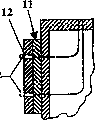
Figure 12 is the emittance transmission system of the present invention of Fig. 1 and the partial sectional view of clamper pin, demonstrates the stationary laser beam embodiment, and it demonstrates the light beam of the whole diameter that has been full of the clamper pin with the top view of clamper pin;
Figure 13 is the partial sectional view of the optional embodiment of emittance transmission system and clamper pin, demonstrates motion light beam embodiment, and it demonstrates the light beam of a part of diameter that only has been full of the clamper pin with the top view of clamper pin; And
Figure 14 is the partial sectional view of the optional embodiment of emittance transmission system and clamper pin, demonstrates clamper pin bulb.
The specific embodiment
The present invention needing can be configured for any manufacturing operation of holding workpiece.Explanation for example, here the embodiment that is comprised relates to machined in batches, makes purposes but be not limited to these.
Comprise clamper pin 12, emittance transmission system 14, clamper pin base plate 16 and detachable/collapsible alignment pin 18 and locating shim 19 in the present invention shown in Fig. 1 and 2 10.Also demonstrate radiant energy source 22, optical path selective system 24, light guide therefor 30 and light guide therefor base plate 32.They are the building block of emittance transmission system 14.Computer control system 58 has been controlled from the emission to clamper pin 12 of the emittance of emittance transmission system 14.Rdaiation response bonding agent 20 is applied to the contact surface 26 of clamper pin 12 so that workpiece 28 is bonded on these clamper pins 12.Clamper pin base plate 16 and light guide therefor base plate 32 are installed on the substrate (tombstone) 42 to form anchor clamps 11.
The high power capacity machined is used normally for example having and is carried out on the four axle horizontal automatic numerical control lathes of pallet exchange capacity.In this case, anchor clamps 11 are installed on of two rotary tables of lathe (not shown).Carry out workpiece loading and unloading outside at this automatic numerical control lathe when Digit Control Machine Tool is being processed the part that is installed on similar support-chucking appliance system.The geometry variability of surface of the work is less relatively.This can be such a case, and they form by for example rolling, extrusion molding, machined, powder processing or die casting.
Clamper pin base plate 16 is for keeping the structural matrix of clamper pin 12.An embodiment of anchor clamps 11 comprises one group of clamper pin base plate 16, and each is designed to consistent in the bottom surface of the workpiece shown in Fig. 3 28.The number of clamper pin base plate 16 and space arrange with the number of the clamper pin 12 that is comprised and space to arrange to be special-purpose here.
Rdaiation response bonding agent 20 its intensity and durability are enough on its desired life-span clamper pin 12 be kept motionless.Rdaiation response bonding agent 20 optically is transparent, and has about 1.5 refractive index.Because the light that the refractive index of clamper pin 12, is passed clamper pin 12 apparently higher than rdaiation response bonding agent 20 and clashed into its side will carry out near internal reflection completely.Increased the transmissivity of clamper pin 12 thus.
Clamper pin base plate 16 is combined with alignment pin 18 and locating shim 19, is used to make workpiece with respect to clamper pin 12 and machined datum mark reference frame location, and makes workpiece with respect to all clamper pin 12 location on anchor clamps 11.Alignment pin 18 and locating shim 19 assemble after deposition rdaiation response bonding agent 20 and before workpiece 28 is being installed and/or extend.Keeper 18,19 is not a load bearing component.Therefore, in case workpiece 28 is bonded on the anchor clamps 11, can keeper 18,19 be broken away from so that the bigger passage that fabrication tool leads to workpiece 28 that is used for is provided by removal, contraction or other means.In addition, locating shim 19 forms gap 56 between workpiece 28 and clamper pin base plate 16.
In preferred embodiments, clamper pin base plate 16 is fixing with respect to anchor clamps base plate or substrate 42, because the surface of the work 54 that adheres to has minimum form error.But, workpiece adhesive surface 54 has under the situation of tangible form error therein, as being desired the same under the situation about forming by sand casting process for example at it, optional embodiment (not shown) permission can be carried out relative motion between clamper pin base plate 16 and anchor clamps base plate or substrate 42.This optional embodiment workpiece 28 pressing against on alignment pin 18 and the locating shim 19 during prevent from unexpectedly to contact with workpiece 28.This optional embodiment also is used for making gap 56 minimums between workpiece 28 and clamper pin 12.In these situations, what can expect is, clamper pin base plate 16 can according to can reconcile the similar mode of mechanical support and actuate and move with respect to surface of the work.
Light guide therefor 30 for be used for by it with emittance for example light be transferred to the photoconductive tube of clamper pin 12.Each light guide therefor 30 is fixed in the appropriate location with respect to clamper pin 12.The emittance of sending from light guide therefor 30 is disperseed and is left with predetermined angle.Emittance enters clamper pin 12, and directly is transmitted on clamper pin-bonding agent interface 66, perhaps is transmitted on it after internal reflection.Whole clamper pin-bonding agent interface 55 with basically uniformly irradiation level shone.The big young pathbreaker of irradiation level is directly proportional with the power of transmitted radiation energy and is inversely proportional to the cross-sectional area of clamper pin exit surface 36.
An embodiment of light guide therefor 30 is commercially available fiber optic cables, goes for for for example excimers and the use of YAG laser instrument of radiant energy source.This light guide therefor is made by Ceramoptec.Another embodiment of light guide therefor is made by Lumatech.
Light guide therefor base plate 32 is for being used for the structural matrix of light guide therefor 30.According to clamper pin 12 similar modes, use rdaiation response bonding agent 20 for example Dymax 602 light guide therefor 30 is bonded on the hole 38 of base plate 32.But the bonding agent of any appropriate all is acceptable.
Clamper pin base plate 16 and light guide therefor base plate 32 preferably link together with bolt, and by alignment pin 40 control its alignings (referring to Fig. 2).Preferred use two base plates rather than one so that the assembling of anchor clamps 11 and dismounting, and reduce to repair in use impaired clamping pin 12 required time, energy and expense.Light guide therefor base plate 32 directly is connected on the substrate 42 (Fig. 1) that is installed on the substrate pedestal 44.
Optional embodiment (Figure 13) has utilized clamper pin 12 as the function that replaces the window of above-mentioned static light guide therefor with the motion light guide therefor or the direct transmitted light beam that moves.
In this embodiment, clamper pin 12 is as the carrying window.Motion light beam 76 enters clamper pin exit surface 36.This light beam 76 has the fixed diameter d less than clamper pin D, and moves along circular path 74.Therefore, the light that clamper pin 12 is passed in transmission can not illuminate whole clamping pin exit surface 36, and just illuminates its part.The light 75 that enters clamper pin incidence surface 60 also is the light beam with fixed diameter, and moves along circular path.Enter the collimation lens 68 that is used for this light is gathered into light beam and produce these motion light beams by making diverging light 77 pass static light guide therefor 30 with fixed diameter d.The level crossing 70 around the axis rotation of clamper pin 12 is left in collimated light beam 79 reflections.This level crossing 70 is fixed on the rotating machinery device 72 that is contained in the light guide therefor base plate 32.This rotating machinery device 73 by traditional means for example electric, pneumatic or hydraulic pressure means actuate.
Perhaps, by the condenser lens (not shown) that increases between collimation lens and clamper pin the diameter d of light beam 75 that enters clamper pin 12 and the light beam 76 that leaves clamper pin 12 is enlarged or contraction.
Another optional embodiment (not shown) provides to the clamper pin by the direct beam transmission from the responsive radiation energy source and solidifies the light and the light of loosening, and therefore need not light guide therefor and light guide therefor base plate.By being used to make light beam make the incidence surface of clamper pin be exposed to direct beam to the device of next clamper pin motion from a clamper pin.Be used to make the device of this beam motion to utilize and replace light guide therefor by for example lens, fixed mirror, the optical system of actuating mirror and/or actuating elements such as axle.In these situations, should exist in the transparent channel in the back side of anchor clamps base plate or substrate.
As mentioned above, rdaiation response bonding agent 20 is for example Dymax 602 of photocurable structural adhesive.Commercially available bonding agent 20 when to be exposed to wavelength be the emittance of 300nm to 550nm with polymerization.Rdaiation response bonding agent 20 can be constant (or pure), perhaps with colouring agent for example pigment, dyestuff or other chemical addition agent mix so that improve the loosen ability (will describe in detail below) of light of its absorption, thus with the absorption spectrum fine tune of these bonding agents to the specific wavelength in bonding and the scope of loosening.
Making a long way off because light must see through bonding location fully, the bonding agent at bonding agent-workpiece interface 62 places solidifies.See through Beer-Lambert ' the s law of the curing light of this bonding agent in accordance with light absorption.Therefore, the irradiance rate of the light beam that is transmitted and length of penetration exponent function relation reduce.Attenuation rate is by the absorption coefficient decision relevant with bonding agent.Because pure bonding agent optically is transparent, must be extremely low for the absorption coefficient of all wavelengths.
The rdaiation response bonding agent comprises light trigger.When the electromagnetic radiation that is exposed in specific wavestrip, these light triggers become free radical.Cause the very low 10mJ/cm that is approximately of the required minimum exposure amount of cross-linking polymerization
2The cross-linking polymerization process lasts till without any more light trigger always and can be used for free radicalization.The polymerisation degree is relevant with light exposure (J/cm2) exponentially.Polymerization rate is subjected to curing the irradiation level (W/cm of light to a great extent
2) control.Irradiation level is high more, light exposure is big more, so curing rate is fast more.The rdaiation response bonding agent solidifies in 5 seconds or less time being exposed in ultraviolet ray and blue spectrum (wavelength is 300nm to 550nm) or when being exposed to high-velocity electrons (referring to following table 1 and 2).
Acrylic rdaiation response bonding agent is widely used in a large amount of electronic products of assembling by for example Loctite and Dymax manufacturing.The acrylic bonding agent includes the light trigger of various compositions and quantity.As mentioned above, the light time of light trigger in the wave-length coverage that is exposed at 300nm to 550nm will form free radical, and this causes and propagated the cross-linking polymerization of bonding agent conversely.The additive that does not need to be used for free radicalization by the bonding agent of electron beam emission curing.On the contrary make the direct free radicalization of monomer in the bonding agent by interaction with the high-velocity electrons that penetrate.These bonding agent toxicity are lower and can not send VOC.They also have usually the pot-life greater than 1 year.
Because these bonding agents all are optically transparent in uncured and solid state, so they have absorbed the radiation that is included in the light in 300nm to the 550nm scope in UVA and visible spectrum seldom.In case solidify, then bonding agent is absorbed in this ability than the light in the close limit and further reduces.As mentioned above, can add in this bonding agent that colouring agent comprises pigment, dyestuff or some other chemical material so that strengthen the absorption (being further described below) of the light of loosening.
The light of perfect additive transmission in the absorption band of the light trigger of bonding agent (preferred 300nm to 550nm), and be absorbed in the light of loosening outside this frequency spectrum (preferably between 600nm and 1064nm) easily.The use of additive can not hinder solidification process, and conveying is relatively cheap in the expense of the light of loosening at provision wavelengths place.
Being exemplified as by what Gentex made of this interpolation is used in dyestuff in laser protective eyewear and the sealing cover plate.These plastics protect the order panel designs become its wavelength of transmission in visible spectrum special frequency band and be absorbed in wavelength in those frequency band ranges of those common lasers (excimers, Nd:YAG etc.).Because light-curing adhesive is a polymer, so can expect, adds the absorptivity that this dyestuff will improve bonding agent.
An embodiment of mixed radiation response bonding agent 20 for example its weight ratio is 99.5% pure bonding agent (for example Dymax 602) and 0.5% colouring agent (for example carbon black).But, it is suitable comprising that its refractive index of 90% to 99.9% is approximately the colouring agent of 1.5 substantially transparent rdaiation response structural adhesive and 0.1% to 10% and is enough to solidify or destroy bonding any complex response adhesive mixture, and within the scope of the invention.
The carbon black coloring agent is for example combined with laser near infrared spectrum well by the Raven790 that Columbian Chemical Co. makes, and only needs less concentration, and can not reduce and solidify bonding intensity fully.This dyestuff is absorbed in the light that solidifies in the wave spectrum easily, and stops the transmission of curing light to pass this bonding location.
In solidification process, the bonding agent part that receives minimum exposure is with minimum curing, so its intensity is the most weak.Minimum consolidation zone is generally from the nearest zone of bonding agent-workpiece interface 62.Because the intensity of whole bonding location is subjected to its restriction of the intensity in weak zone, so the intensity of bonding agent will always be subjected to the restriction at the total exposure at bonding agent-workpiece interface 62 places.Therefore, the high more then curing of curing luminous radiance is fast more and dark more.
It is very low to cause the required light exposure of the curing of rdaiation response bonding agent 20, is approximately 10mJ/cm
2Being to make 0.003, " it is quite low that bonding portion solidifies required light irradiance rapidly, is approximately 1W/cm for pure bonding agent
2Perhaps still less, the bonding portion for the band dyestuff of same thickness is 8W/cm
2Or still less (referring to following table 1 and 2 to obtain further details).
At room temperature, it is quite high to solidify the intensity of bonding portion fully.For example, be generally greater than 6000psi in clamper pin 12 and workpiece 28 its final hot strengths with level and smooth metal surface.But, if its temperature is apparently higher than the operating temperature of its regulation (300/150 ℃) limited time then forever reduced and solidify the intensity of bonding portion for example, thereby cause the carbonization of rdaiation response bonding agent 20 and the chemical bond of rdaiation response bonding agent 20 to destroy.
For loosening, by the bonding bonding portion of structural adhesive by heat, chemistry or mechanically (that is, the coupling part is drawn back) destruction (or structure reduction).For example, typically destroyed when being higher than 300 °F/150 ℃ based on acrylic acid contact temperature that is bonded in.In addition, by make it to be exposed to chemical material for example paint stripper destroy bonding portion, but than thermal degradation slowly many.
Thereby be transmitted to the temperature that makes bonding agent-workpiece interface on the surface of the work and rise and to be higher than the short scheduled time of operating temperature by making the laser beam that is approximately 600nm to 1064nm pass pure bonding agent, realize loosening or the structure reduction of bonding portion.Because the duration is very short, so the heat that is delivered on the workpiece body can be ignored.
As mentioned above, the bonding agent and the pure bonding agent of additive that will have as the good absorption agent of the light of loosening compares.This additive will improve absorptivity and the heat conversion of bonding portion to radiation, and less heat is sent on the workpiece.This additive will generate heat rapidly and send this heat on every side bonding agent by conduction subsequently.The present invention for example passes with the bonding agent of look or the bond layer of band dyestuff the light transmission, and heating surpasses the bonding agent operating temperature, and bonding around the surface breakdown of workpiece.The bonding agent that use has an additive is obviously more effective than the bonding agent that does not have additive aspect the required emittance of loosening, and its average light irradiation level of loosening is approximately 1000W/cm2.
From experimental observation (below table 1 and 2) as can be seen carbon black percentage solidifying the effect on the solidification process and the process of loosening under the situation that light irradiance is constant and the light irradiance of loosening is constant:
1. carbon black percentage is big more, and the parasitic absorptivity of then solidifying light is big more, and the maximum curing depth of bonding portion is more little, and realizes that complete bonding strength is long more required hardening time; And
2. carbon black percentage is big more, and the time that the absorptivity of the light of then loosening is big more and the bonding portion of loosening is required is short more.
In addition, if carbon black percentage keeps constant with the irradiation level that solidifies the light and the light of loosening, then for bonding portion thickness, exist following true:
1. therefore the bonding portion of the about maximum curing depth of its thickness will be lower than the coupling part of maximum curing depth without any adhesive strength for its thickness at bonding agent-workpiece interface place without any intensity;
2. bonding portion thickness is big more, then the coupling part that is lower than maximum cured thickness for its thickness arrives that to solidify the required time fully long more, bonding portion thickness is big more, and then to absorb the ability of the light of loosening big more in the coupling part, and loosens that to solidify the required time of bonding portion short more; And
3. solidify light irradiance big more and loosen light irradiance more senior general cause bigger maximum curing depth, shorter hardening time and short loosening the time.
Table 1 has been summed up the curing bonding strength relevant with the solidification process variable with various bonding agents below.
| Carbon black percentage | Coupling part thickness (inch) | Solidify light irradiance (W/cm 2) | Hardening time (s) | Final bonding portion intensity (psi) |
| ??0 | ??0.003 | ??1.35 | ?20 | ??7195 |
| ??0 | ??0.005 | ??1.35 | ?20 | ??7011 |
| ??0.5 | ??0.002 | ??1.35 | ?60 | ??7080 |
| ??0.5 | ??0.003 | ??1.35 | ?5 | ??3379 |
| ??0.5 | ??0.003 | ??1.35 | ?20 | ??5023 |
| ??0.5 | ??0.003 | ??1.35 | ?30 | ??5611 |
| ??0.5 | ??0.003 | ??1.35 | ?60 | ??6821 |
| ??1 | ??0.000 | ??1.35 | ?20 | ??7215 |
| ??1 | ??0.001 | ??1.35 | ?20 | ??5848 |
| ??1 | ??0.002 | ??1.35 | ?20 | ??420 |
| ??1 | ??0.003 | ??1.35 | ?20 | ??0 |
| ??0 | ??0.003 | ??7.85 | ?10 | ??7143 |
| ??0 | ??0.005 | ??7.85 | ?20 | ??8277 |
| ??0.5 | ??0.003 | ??7.85 | ?5 | ??6245 |
| ??0.5 | ??0.003 | ??7.85 | ?10 | ??7093 |
| ??0.5 | ??0.005 | ??7.85 | ?10 | ??5860 |
| ??0.5 | ??0.005 | ??7.85 | ?20 | ??5952 |
| ??1 | ??0.003 | ??7.85 | ?30 | ??0 |
Table 2 has been summed up and the various bonding agents and the relevant remnants of the process variables coupling part intensity of loosening of loosening below.
| Carbon black percentage | Coupling part thickness (inch) | Light average irradiance (W/cm loosens 2) | (s) loosens the time | Final bonding portion intensity (psi) |
| ??0 | ??0.003 | ??1270 | ?0.2 | ??6884 |
| ??0.2 | ??0.001 | ??1270 | ?0.2 | ??7045 |
| ??0.2 | ??0.003 | ??1270 | ?0.2 | ??5670 |
| ??0.5 | ??0.001 | ??1270 | ?0.2 | ??1034 |
| ??0.5 | ??0.003 | ??1270 | ?0.2 | ??363 |
Referring again to Fig. 1, emittance transmissive system 14 comprises radiant energy source 22 and optical path selective system 24.Radiant energy source 22 produces light or the emittance that is used to make rdaiation response bonding agent 20 to solidify or loosens or may the both have.Cure lamp (short arc, mercury vapour) by broad band wavelength and produce the emittance that is used to solidify.The laser instrument (have the excimers (351nm) of XeF admixture of gas, two Nd:YAG (532nm)) of its wavelength in the absorption band of bonding agent produces and is used to make bonding agent to solidify and destroys bonding and be formed on remaining bonding agent substrate 52 on the workpiece and the emittance of clamper pin exit surface 36.Laser instrument is preferred for producing higher required irradiation level, and emittance needs to make rdaiation response bonding agent 20 to destroy.Use laser instrument preferably to use two or three Nd:YAG (355nm) of pulse to come curing adhesive and destroy bonding agent.
For radiant energy source 22, a light source that is used for solidifying these bonding agents is that as seen UV cures lamp.The UV visible lamp has adopted metal halide bulb or electrodeless fusion bulb, and it launches the wide wavelength range in UVA and visible spectrum.But most of emittance concentrate between 300nm and the 550nm.In this spectral region, peak transmission occurs at less wavelength place.By the Chemical Regulation light trigger, make the absorption spectrum of bonding agent and these peak values closely cooperate.
The UV visible light cures lamp the light that is used for the bonding agent 20 of curing radiation response simultaneously is provided.For example, to cure lamp can be that the light guide therefor of 5mm is launched the light that its average irradiance is 10W/cm2 (320nm-450nm) by core diameters for 200 watts in Dymax blue light ripple.
Use laser instrument to be better than using and cure lamp.Because from laser instrument send only relevant, this light accumulates in much smaller spot size, has therefore obviously increased the irradiation level that cures light.Opposite this can be used for formulating bigger curing depth and/or littler cure cycle time, and this helps including the curing of the bonding agent that solidifies interference of light additive.
Equally, use the identical much smaller light guide therefor of incoherent light of specific strength to transmit coherent light.In addition, can the absorption band of bonding agent be adjusted to the wavelength of laser instrument by the light trigger that Chemical Regulation is provided by bonding agent supplier.Like this, the efficient of solidification process is optimized.
Commercially available Pulse Nd: the YAG laser instrument (1064nm) provide the light that is used to destroy bonding agent, because its light is transmitted with higher irradiation level by fibre-optic light guide spare.To close energy lower because destroy the required power of single curing adhesive, so use pulsed light.The power demand of this laser instrument depends on many factors.
Optionally the laser instrument embodiment is the laser instrument that is applicable to the rdaiation response bonding agent 20 of loosening, and it is launched and is used in part second destruction bonding portion 64 and passes to workpiece 28 or the heat of clamper pin base plate 16 can be ignored.The destruction of bonding portion is because the thermal degradation of bonding portion 64.
An embodiment, emittance guides to light guide therefor 30 from radiant energy source 22 by optical router 46.The emittance that is transmitted by optical router 46 passes to light guide therefor base plate 32 by light guide therefor 30.This light guide therefor 30 can be connected with substrate 42 to finish the optic network between radiant energy source 22 and clamper pin 12 by clamper pin 16.
Optics route selection system 24 comprises the network of optical channel, and it can for example a little light guide therefor of light or liquid light guides part close any or combination in the light beam guiding device in order to open passage, mirror, lens, light guide therefor.Computer control system 58 is connected with the emittance transmit network with optical channel, so that the path and the energy level of the emittance of control from radiant energy source 22 to clamper pin 12.Can add light shielding part and wait in general area, to protect operating personnel.
After making, workpiece 28 and anchor clamps 11 are thrown off by being exposed to than solidifying.For example, laser-transmitting passes clamper pin 12 and is mapped on the bonding portion 64.Bonding portion 64 is in part thermal degradation in second, and the heat that passes on clamper pin 12, clamper pin base plate 16 or the workpiece 28 can be ignored.The process of loosening can not damaged clamper pin 12, clamper pin base plate 16 or workpiece 28.
After the process of loosening, from anchor clamps 11, workpiece 28 is removed.Laser instrument (example of radiant energy source 22) for example can stay thermal degradation or remaining bonding agent substrate 52 on the surface of workpiece gluing of surfaces 54 and clamper pin 12.Should be before distributing new rdaiation response bonding agent 20 under can not be, from clamper pin 12, will degrade or remaining bonding agent substrate 52 removals to clamper pin 12 hurtful situations.By manually cleaning with the metal scouring pad or with the power belt sander or be equal to machinery and clean automatically from clamper pin contacts surface and to remove thermal degradation or remaining bonding agent substrate.Being used for that coarse steel/copper scouring pad manually cleans is the method for optimizing of removing this degraded or remaining bonding agent substrate 52.But, reduced the scouring time and reduced human labour with driven power belt sander 50 pneumatic scouring pads that combine.Cleaning process in arbitrary situation can not damaged clamper pin 12 and clamper pin base plate 16.
If necessary, apply similar scouring process to remove remaining bonding agent substrate 52 (Figure 10) to workpiece adhesive surface 54.
Perhaps, can use for example toluene or other powerful solvent acetone or be immersed in chemical stripper on the tiny steel wool and combine and from workpiece, remove degraded or remaining bonding agent substrate 52 for example of a part purging system and chemical substance.Can use the traditional part purging system that has utilized above-mentioned these solvents to come cleaning workpiece in batches.
Get back to Fig. 1, additional building block of the present invention 10 comprises bonding agent distributor 48 (commercially available) and has the air sander of scouring pad annex 50.
Referring now to Fig. 4-11, these figure demonstrate the workpiece of loosening are bonded in process on the anchor clamps of the present invention.
Step 1: bonding agent distributor 48 is assigned to a rdaiation response bonding agent 20 on the contact surface 26 of each clamper pin 12 (Fig. 4).
Step 2: alignment pin 18 and locating shim 19 stretched and/or be assemblied on the clamper pin base plate 16 (Fig. 5).
Step 3: workpiece 28 is installed on alignment pin 18 and the locating shim 19 (Fig. 6), workpiece 28 is located with reference to frame with respect to lathe.Rdaiation response bonding agent 20 at each clamper pin 12 place spreads between workpiece 28 and clamper pin 12.According to the shape variable of workpiece adhesive surface 54, the nominal gap 56 between each clamper pin 12 and workpiece 28 is approximately 0.003 inch.The institute that this rdaiation response bonding agent 20 has been filled between workpiece 28 and clamper pin 12 is gapped, and can not cause any tangible masterpiece to be used on the workpiece 28.
Step 4: the light guide therefor base plate 22 that is connected with radiant energy source 22 by light guide therefor 30 is installed in (Fig. 7) on the substrate 42.But radiant energy source 22 other mounting structure (not shown) on substrate 42 or other securing member also is suitable for, and within the scope of the invention.Radiant energy source 22 is sent with wide about 3 to 10 seconds time of the curing of emittance (being approximately 300nm to 550nm) form simultaneously to all clamper pins 12 subsequently.Last in this transmission, all bonding agent drops 20 are fully solidified or fixed with the bonding portion that forms bonding work pieces 28 and anchor clamps 11 and provide 6000psi or bigger hot strength.
Step 5: can make alignment pin 18 and locating shim 19 in case of necessity from 16 withdrawals of clamper pin base plate and/or removal (Fig. 8).Subsequently, anchor clamps 11 are delivered to the automatic numerical control lathe so that carry out the part machined.
Step 6: after making, anchor clamps 11 are loosened program to separate workpiece 28 from anchor clamps 11.Photoconduction chassis 32 is connected to the radiation energy 22 (Fig. 9) that for example is connected with substrate 42.Optical routing system 24 transmits the train of pulse of laser beam (approximately 300nm-550nm) to each bonded joint 64.Each train of pulse continues about .05 second to the .2 duration of second, and this depends on the thickness of bonded joint.Train of pulse is absorbed by the joint adhesive, and thermal degradation.In this process, be transferred to workpiece 28, promptly sell 12 and the heat of promptly selling chassis 16 can ignore.
Step 7: remove workpiece 28 (Figure 10) from anchor clamps 11.At workpiece 28 with promptly sell the adhesive 52 of residual fraction thermal degradation on 12 the contact surface.In addition, uncured rdaiation response adhesive 20 can keep from the teeth outwards and can not be exposed to the curing radiation energy.
Step 8: at first utilize the rag of alcohol immersion to remove the uncured rdaiation response adhesive of promptly selling on the chassis 20.Utilization is washed away pad or is had pneumatic sand blasting machine 50 manual the removing of washing away the pad annex and promptly sells 12 lip-deep thermal degradations or residual adhesive substrate 52 (Figure 11).Perhaps can utilize manipulator and pneumatic sand blasting machine to remove residue automatically.Thermal degradation on the workpiece or residual adhesive substrate 52 can be processed in device subsequently and remove or clean in the post processing of processing work.
The foregoing description has shown implements a mode of the present invention, but can implement the present invention in a different manner.The influence of the concrete feature that its embodiment can be used.The significant effects factor will comprise that workpiece geometries and how much variabilities, workpiece circulation timei, part quality requirement, machining tool carry out ability and the anchor clamps reconstruct and the flexibility requirement of process operation.
Another embodiment considers or uses additive, and it can cause solidifying the interference of light, and (adherent) surface of the work that wherein adheres to is level and smooth relatively and be subjected to little how much and change.That the example that can produce the initiating process of such surface of the work comprises is rolling, extrude, machined, powder-processed (powder processes) and die casting.It is preferably static promptly to sell chassis 16, promptly sell 12 and workpiece between normal clearance thickness should be .005 inch or littler.Use traditional cure lamp to come cure adhesive.Adhesive joint can have bigger joint stiffness, and in fact can not transmit to surface of the work heat.
Under the situation of thick adhesive joint (greater than 0.003 inch), exist four selections in order to solidify joint.First selection is to use pure optically transparent adhesive (the easiest curing), but the process of loosening can depend on the heating of adhesive-workpiece interface.This can loosen light energy greatly with the adhesive of loosening, and therefore may need more powerful loosening light source or the longer circulation timei of loosening and handling.
Second selection is to use painted slightly adhesive (less than the colouring agent of 0.5% percentage by weight).This may need stronger curing light source and/or longer slightly bonding processing circulation timei.But loosen light source and processing and keep roughly the same.
The 3rd selection be to use same painted adhesive (colouring agent of 0.5% percentage by weight) and use select than first and second in the much bigger curing light source of power laser for example.
The 4th selection is to produce the multi-layer adhesive joint, comprises the thick-layer (for example 0.001 inch to 0.05 inch thick) of the pure adhesive of the thin layer that is bonded to colored adhesive (colouring agent of 0.5% percentage by weight) (for example 0.001 inch thick to the .003 inch).In this case, as pre-treatment step, apply a spot of colored adhesive of coating to the surface of the work that adheres to, and the employed curing light source of bonding painted joint and same curing light source and the bonding process of bonding process that utilize and be less than or equal to the .003 inch carry out semi-solid preparation.The top surface of joint can be because the inhibition of oxygen keeps semi-solid preparation.In workpiece loading cycle, the colored adhesive of semi-solid preparation can contact with uncured pure adhesive.Then as previously mentioned, uncured adhesive and can solidify with the interface of colored adhesive.
If preferred, can in pre-treatment step, use light source, to reduce the cure cycle time than high irradiance.By beam bombardment (radiation curing of another kind of form) or heat cure (Luo Liru uses baking oven) or use chemical activating agent also can solidify the colored adhesive of a small amount of coating.In these processes any can both cause the curing fully of the colored adhesive under adhesive-air interface, and guarantees that top surface is owing to oxygen suppresses to keep semi-solid preparation.
In workpiece loading cycle, promptly selling the pure rdaiation response adhesive 20 of deposition on 12.Then workpiece 28 is installed on locator pins 18 and the locator pad 19, makes the semi-solid preparation adhesive contact with uncured pure adhesive.Pure adhesive solidify and be bonded to promptly sell 12 and with the surface-crosslinked polymerization of the semi-solid preparation of colored adhesive.This process can promptly sell 12 and workpiece 28 between cause completely crued bonding.
Test for the adhesive joint that the .005 inch is thick.In these cases, at the layer of surface of the work deposition .002 inch to 0.5% colored adhesive of .003 inch.Utilize hand to keep photoconduction, utilize the low-light (level) light beam (<1.682W/cm2) with adhesive semi-solid preparation 20 seconds.After semi-solid preparation, make colored adhesive contact with uncured pure adhesive on the pin promptly, utilize higher illuminance light (7.85W/cm2) the cure adhesive joint 10 seconds by promptly selling transmission.The joint that this process produced is according to the intensity of routine acquisition greater than 7480psi.In addition, when bearing the light of loosening (1270W/cm2) .2 in the time of second, the residual strength of adhesive joint is approximately less than 460N.
Bonding another kind of method provides and can form the bonding enough maintenance intensity that realizes of adhesive at the interface by seam crossing rather than the zone between workpiece and anchor clamps 11 in anchor clamps-workpiece joints.The embodiment of this replacement provides the greater flexibility about the curing and the emittance transmission of loosening.
In fact, simply direct beam, radiation transmission are enough to be used in the curing of adhesive and loosen.As a result, not needing anchor clamps 11 is the Beam Control equipment of optical transmissive elements or any other form.And this another embodiment can provide greater flexibility about radiant energy source.Herein, be cured by light beam from cure lamp, laser instrument or electron beam emitter.In addition, loosen by laser instrument or electron beam emitter.The structural adhesive of rdaiation response can be be used for electron beam transmission situation under the different different compositions of conventional adhesive of Photocurable adhesive.
The radiation energy of replacing is integrated in promptly to sell goes up (Figure 14).As mentioned above, promptly pin is preferably made by for example sapphire material, its very firm, hard and rigidity, and can optical transmission in the emittance of UVA or near infrared band, light for example.Promptly pin is made with bearing load, being filled with the metal halide bulb 78 of gas of two electrodes 82.Adopt traditional means that traditional electrode 82 and gas are enclosed in the bulb that bears load.Gas be can emission wavelength ranges when the voltage by predeterminated level excites in any known gas of the emittance of 300nm to 550nm, metal halide gas for example.The electric wire 84 that connects the electrode 82 promptly sell bulb 78 leads to traditional power supply 86 by photoconduction chassis 32 and anchor clamps daughter board or substrate (see figure 1).
In the adhesive bonding process, power supply produces the gas that enough voltage is contained to excite wherein to electrode.The gas that excites sends radiation, and for example light comes cure adhesive.
In adhesive is loosened process, laser by be used for as mentioned above solid promptly pin promptly sell the bulb transmission.But in this embodiment, light is also by the gas of filling in the bulb and promptly sell the material transmission.
It will be appreciated by those skilled in the art that, other embodiment, improvement, details and use can be consistent with disclosed literal in front and spirit, and drop in the scope only defined by the appended claims of this patent, and this scope is according to Patent Law, and comprise and make an explanation doctrine of equivalents.
Claims (31)
1. piece-holder method, it may further comprise the steps:
The first rdaiation response bonding agent is distributed on the fixed surface of anchor clamps;
With workpiece setting near fixed surface;
The described first rdaiation response bonding agent is inserted between described fixed surface and the workpiece;
The emittance that makes the described first rdaiation response bonding agent be exposed to first predetermined level continues first predetermined amount of time, make be enough to solidify the first rdaiation response bonding agent and between workpiece and fixed surface, form bonding,
Described workpiece and anchor clamps are interconnected.
2. the method for claim 1, in order after interconnection, workpiece to be separated in anchor clamps, comprise that also the emittance that makes bonding portion be exposed to second predetermined level continues second predetermined amount of time, making is enough to structurally weaken bonding between workpiece and anchor clamps, and workpiece and anchor clamps are thrown off.
3. method as claimed in claim 2 also comprises the step of removing any remaining bonding agent substrate from fixed surface.
4. method as claimed in claim 2 also comprises the step of removing any remaining bonding agent substrate from workpiece.
5. the method for claim 1, further comprising the steps of:
The second rdaiation response bonding agent is distributed on the workpiece;
Make the second rdaiation response bonding agent on workpiece be cured to semi-cured state; And
Workpiece with semi-solid preparation second rdaiation response bonding agent is contacted with the first rdaiation response bonding agent on fixed surface.
6. the method for claim 1 also comprises light absorption rdaiation response bonding agent is distributed in step on the first rdaiation response bonding agent.
7. the method for claim 1, the wherein said first rdaiation response bonding agent comprises the light absorption additive.
8. one kind is used for fixing the bonding agent piece-holder system that makes workpiece, comprising:
One anchor clamps, it has the radiation transmission fixed surface;
One emittance transmission system, it can the emitted radiation energy;
Described emittance transmission system is arranged near the described radiation transmission fixed surface and optical communication with it; And
The described emittance that described radiation transmission fixed surface can transmission be sent by described emittance transmission system.
9. system as claimed in claim 8, wherein:
Described radiation transmission fixed surface can the transmission of electromagnetic radiation energy; And
Described emittance transmission system can be launched electromagnetic radiation energy.
10. system as claimed in claim 8, wherein:
Described radiation transmission fixed surface can the transmission electron beam emittance; And
Described emittance transmission system can the divergent bundle emittance.
11. system as claimed in claim 8, wherein said radiation transmission fixed surface is made by being selected from sapphire, diamond, monocrystal silica, ruby, three zirconias and zirconic material.
12. system as claimed in claim 8, wherein said emittance transmission system comprises a radiant energy source and optical channel network.
13. system as claimed in claim 12, wherein said optical channel network and described anchor clamps are integral.
14. system as claimed in claim 13, wherein:
Described optical channel network comprises an input and an output;
Described output is positioned near the described radiation transmission fixed surface;
Described input is positioned near the described radiant energy source; And
Described radiant energy source can the emitted radiation energy.
15. system as claimed in claim 14, the described output of wherein said optical channel network can be sent to the stationary radiant energy bundle that is produced by described radiant energy source on the described radiation transmission fixed surface.
16. system as claimed in claim 14, wherein:
Described emittance transmission system also is included in the directed source of emittance of optical communication between described optical channel network and the described radiation transmission fixed surface; And
The directed source of described emittance can be directed to the emittance that is transmitted by described optical channel network on the described radiation transmission fixed surface.
17. system as claimed in claim 12, wherein said radiant energy source can be transmitted in the emittance in the wave-length coverage of 300nm to 1064nm.
18. system as claimed in claim 12 is used for workpiece is bonded in described radiation transmission fixed surface, wherein said radiant energy source can be transmitted in the emittance in the wave-length coverage of 300nm to 550nm.
19. system as claimed in claim 12 is used to make workpiece to separate in described radiation transmission fixed surface, wherein said radiant energy source can be transmitted in the emittance in the wave-length coverage of 600nm to 1064nm.
20. system as claimed in claim 8, wherein said anchor clamps also comprise:
The machinery keeper is used to make workpiece to locate with respect to described anchor clamps; And
Described mechanical keeper defines predetermined gap between workpiece and described radiation transmission fixed surface.
21. system as claimed in claim 20, wherein said mechanical keeper can be thrown off, and described thus mechanical keeper can not hinder manufacturing.
22. system as claimed in claim 20, wherein said mechanical keeper can be removed, and described thus mechanical keeper can not hinder manufacturing.
23. system as claimed in claim 20, wherein said mechanical keeper can bounce back, and described thus mechanical keeper can not hinder manufacturing.
24. system as claimed in claim 12, wherein: described optical channel network is selected from the group that is made of reflects light guiding element, reflecting member, mirror and lens.
25. an emittance response adhesive component, it comprises:
The rdaiation response structural adhesive of substantial transparent, its refractive index be approximately 1.5 and percentage by weight be 99% to 99.9%, the colouring agent percentage by weight is 0.1% to 1%.
26. bonding agent as claimed in claim 25, wherein:
Its percentage by weight of rdaiation response structural adhesive of described substantial transparent is approximately 99.5%; And
Described colouring agent is weight percentage and is approximately 0.5% carbon black.
27. a method of producing emittance response adhesive component, it may further comprise the steps:
The rdaiation response structural adhesive of substantial transparent is provided, its refractive index be approximately 1.5 and percentage by weight be 99% to 99.9%;
Provide percentage by weight to be approximately 0.1% to 1% colouring agent; And
Colouring agent is mixed with the rdaiation response structural adhesive of substantial transparent.
28. a method of producing emittance response adhesive component, this method may further comprise the steps:
The rdaiation response structural adhesive of substantial transparent is provided, and its percentage by weight is about 99.5%;
Provide percentage by weight to be approximately 0.5% colouring agent; And
Colouring agent is mixed with the rdaiation response structural adhesive of substantial transparent.
29. product of making by the method for claim 27.
30. product of making by the method for claim 28.
31. system as claimed in claim 8, wherein:
Described radiation transmission fixed surface and described emittance transmission system are one; And
Described integral radiation energy transmission system comprises
The seal carrier bulb, it is made by the material that is selected from the group that sapphire, diamond, monocrystal silica, ruby, three zirconias and silica constitute;
Electrode, they are arranged in the described seal carrier bulb;
Gas, it is arranged in the described seal carrier bulb and can be transmitted in emittance in the wave-length coverage of 300nm to 550nm; And
A plurality of electric wires, they are connected with described electrode.
Applications Claiming Priority (2)
| Application Number | Priority Date | Filing Date | Title |
|---|---|---|---|
| US40214502P | 2002-08-07 | 2002-08-07 | |
| US60/402,145 | 2002-08-07 |
Related Child Applications (2)
| Application Number | Title | Priority Date | Filing Date |
|---|---|---|---|
| CNB2006101031498A Division CN100535071C (en) | 2002-08-07 | 2003-08-06 | System and method for bonding and debonding a workpiece to a manufacturing fixture |
| CNB2006101031500A Division CN100534768C (en) | 2002-08-07 | 2003-08-06 | System and method for bonding and debonding a workpiece to a manufacturing fixture |
Publications (1)
| Publication Number | Publication Date |
|---|---|
| CN1688440A true CN1688440A (en) | 2005-10-26 |
Family
ID=31715795
Family Applications (3)
| Application Number | Title | Priority Date | Filing Date |
|---|---|---|---|
| CNA038235633A Pending CN1688440A (en) | 2002-08-07 | 2003-08-06 | System and method for bonding and debonding a workpiece to a manufacturing fixture |
| CNB2006101031500A Expired - Fee Related CN100534768C (en) | 2002-08-07 | 2003-08-06 | System and method for bonding and debonding a workpiece to a manufacturing fixture |
| CNB2006101031498A Expired - Fee Related CN100535071C (en) | 2002-08-07 | 2003-08-06 | System and method for bonding and debonding a workpiece to a manufacturing fixture |
Family Applications After (2)
| Application Number | Title | Priority Date | Filing Date |
|---|---|---|---|
| CNB2006101031500A Expired - Fee Related CN100534768C (en) | 2002-08-07 | 2003-08-06 | System and method for bonding and debonding a workpiece to a manufacturing fixture |
| CNB2006101031498A Expired - Fee Related CN100535071C (en) | 2002-08-07 | 2003-08-06 | System and method for bonding and debonding a workpiece to a manufacturing fixture |
Country Status (9)
| Country | Link |
|---|---|
| US (2) | US7172676B2 (en) |
| EP (2) | EP1554074A4 (en) |
| JP (1) | JP4485361B2 (en) |
| KR (1) | KR20050061455A (en) |
| CN (3) | CN1688440A (en) |
| AU (1) | AU2003254323A1 (en) |
| CA (1) | CA2494835A1 (en) |
| MX (1) | MXPA05001491A (en) |
| WO (1) | WO2004014587A2 (en) |
Cited By (7)
| Publication number | Priority date | Publication date | Assignee | Title |
|---|---|---|---|---|
| CN101125406B (en) * | 2006-08-16 | 2010-09-29 | 比亚迪股份有限公司 | Ball fixed block and its manufacturing device |
| CN103338896A (en) * | 2011-01-24 | 2013-10-02 | 伯尔霍夫连接技术有限公司 | Assembly head for fixing a fixing element, and fixing method |
| CN104564943A (en) * | 2013-10-09 | 2015-04-29 | 松下电器产业株式会社 | Bonding apparatus |
| CN105324231A (en) * | 2013-06-06 | 2016-02-10 | 德莎欧洲公司 | Method for adhesive bonding by means of heat-activatable adhesive compounds |
| CN107866685A (en) * | 2016-09-27 | 2018-04-03 | 通用电气公司 | For the tool holder component for the component for handling gas-turbine unit |
| CN109702642A (en) * | 2019-02-22 | 2019-05-03 | 龙岩市帝昂光学有限公司 | A kind of C-Lens aperture stabilizing clip |
| CN110230626A (en) * | 2019-04-01 | 2019-09-13 | 苏州市模度智能科技有限公司 | A kind of battery cold welding press-loading apparatus |
Families Citing this family (43)
| Publication number | Priority date | Publication date | Assignee | Title |
|---|---|---|---|---|
| FR2875995B1 (en) * | 2004-09-24 | 2014-10-24 | Oberthur Card Syst Sa | METHOD FOR MOUNTING AN ELECTRONIC COMPONENT ON A SUPPORT, PREFERABLY MOU, AND ELECTRONIC ENTITY THUS OBTAINED, SUCH AS A PASSPORT |
| US20070142498A1 (en) * | 2005-12-20 | 2007-06-21 | Brennan Joan V | Dental compositions including thermally responsive additives, and the use thereof |
| US7896650B2 (en) * | 2005-12-20 | 2011-03-01 | 3M Innovative Properties Company | Dental compositions including radiation-to-heat converters, and the use thereof |
| US7776940B2 (en) * | 2005-12-20 | 2010-08-17 | 3M Innovative Properties Company | Methods for reducing bond strengths, dental compositions, and the use thereof |
| US8026296B2 (en) | 2005-12-20 | 2011-09-27 | 3M Innovative Properties Company | Dental compositions including a thermally labile component, and the use thereof |
| US7524390B2 (en) * | 2006-03-27 | 2009-04-28 | The Penn State Research Foundation | Fixture and method of holding and debonding a workpiece with the fixture |
| DE102008036713A1 (en) | 2008-08-07 | 2010-02-11 | Technische Universität Carolo-Wilhelmina Zu Braunschweig | Method for separating two objects bonded together via at least one adhesive layer |
| DE102009021418A1 (en) | 2009-05-14 | 2010-11-18 | Mtu Aero Engines Gmbh | Device and method for fixing a component to a component carrier |
| DE102009032703A1 (en) | 2009-07-09 | 2011-01-13 | Mtu Aero Engines Gmbh | Device and method for arranging a component on a component carrier |
| DE102010010942B4 (en) * | 2010-03-11 | 2014-05-08 | MTU Aero Engines AG | Clamping device and method for mounting a component on a component carrier |
| US8627626B2 (en) | 2010-04-21 | 2014-01-14 | Russell Boxall | Transferring loads across joints in concrete slabs |
| GB2492548B (en) | 2011-07-04 | 2015-12-30 | Rolls Royce Plc | Adhesive fastening element with first and second members for holding a work piece |
| GB201111320D0 (en) | 2011-07-04 | 2011-08-17 | Rolls Royce Plc | Adhesive fastening elements for holding a workpiece and methods of de-bonding a workpiece from an adhesive fastening |
| GB201111325D0 (en) | 2011-07-04 | 2011-08-17 | Rolls Royce Plc | Adhesive fastening elements for holding a workpiece and methods of de-bonding a workpiece from an adhesive fastening element |
| GB201111315D0 (en) | 2011-07-04 | 2011-08-17 | Rolls Royce Plc | Adhesive fastening elements for holding a workpiece and methods of debonding a workpiece from an adhesive fastening element |
| GB201111312D0 (en) * | 2011-07-04 | 2011-08-17 | Rolls Royce Plc | Adhesive fastening elements for holding a workpiece and methods of de-bonding a workpiece from an adhesive fastening element |
| US8977381B1 (en) * | 2011-09-09 | 2015-03-10 | Jerome Mezzasalma | CNC controlled rotating work piece holding fixtures for a horizontal mill |
| WO2013072439A1 (en) * | 2011-11-16 | 2013-05-23 | Sanofi-Aventis Deutschland Gmbh | Medicament guiding assembly for a drug delivery device |
| CN102493986A (en) * | 2011-12-06 | 2012-06-13 | 中国科学院长春光学精密机械与物理研究所 | Splicing tool with precise and controllable glue layer thickness |
| CA2898453C (en) * | 2013-03-13 | 2021-07-27 | Illumina, Inc. | Multilayer fluidic devices and methods for their fabrication |
| US10046550B2 (en) | 2013-08-22 | 2018-08-14 | Massachusetts Institute Of Technology | Carrier-substrate adhesive system |
| US9448591B2 (en) | 2014-02-21 | 2016-09-20 | Microsoft Technology Licensing, Llc | Compliant battery supports for device testing |
| US9902023B1 (en) | 2014-10-28 | 2018-02-27 | Western Digital (Fremont), Llc | Systems and devices for achieving high throughput attachment and sub-micron alignment of components |
| CN104465270B (en) * | 2014-11-17 | 2016-11-09 | 安徽华东光电技术研究所 | Method for packaging traveling wave tube shell |
| CN105715645B (en) * | 2014-12-05 | 2017-12-22 | 天津航天瑞莱科技有限公司 | A kind of device that high-temperature laminating comprehensive function is provided |
| KR20180067550A (en) * | 2015-10-08 | 2018-06-20 | 메사추세츠 인스티튜트 오브 테크놀로지 | Carrier-substrate adhesion system |
| CN107807318A (en) * | 2016-08-31 | 2018-03-16 | 科大国盾量子技术股份有限公司 | A kind of clamp for testing electronic device |
| DE102017101858A1 (en) | 2017-01-31 | 2018-08-02 | Faurecia Emissions Control Technologies, Germany Gmbh | Exhaust system tensioning device, joining device for an exhaust system, method for clamping and method for joining |
| CN108687442B (en) * | 2017-03-30 | 2021-10-01 | 法拉第未来公司 | System and method for welding |
| US10994384B2 (en) * | 2017-08-17 | 2021-05-04 | Advanced Simulation Technology, Incorporated | Apparatus, system and method for adhesive fixturing of a work piece |
| KR102371611B1 (en) * | 2017-09-01 | 2022-03-07 | 현대자동차주식회사 | Workpiece locator |
| GB201714976D0 (en) * | 2017-09-18 | 2017-11-01 | Rolls Royce Plc | A method and an assembly |
| CN107717779A (en) * | 2017-10-11 | 2018-02-23 | 北京星航机电装备有限公司 | A kind of outer heat-insulated Rigid ceramic tile cemented in place method |
| DE102017221538A1 (en) * | 2017-11-30 | 2019-06-06 | Audi Ag | Detachable adhesive bond and a method for releasing the adhesive bond |
| US10538072B2 (en) * | 2018-04-10 | 2020-01-21 | Gulfstream Aerospace Corporation | Devices and methods for dispensing adhesive elements |
| FR3080554B1 (en) * | 2018-04-25 | 2021-03-12 | Skf Ab | MACHINE FOR GLUING A PART ON A SUPPORT ELEMENT BEFORE MACHINING OPERATIONS AND ITS PROCESS |
| US10906146B2 (en) | 2018-06-22 | 2021-02-02 | Raytheon Technologies Corporation | Zero clamping force conforming fixture |
| CA3131865A1 (en) * | 2019-03-04 | 2020-09-10 | Immunolight, Llc. | Energy augment structures for use with energy emitters and collectors |
| EP3974487A1 (en) * | 2020-09-23 | 2022-03-30 | Ivoclar Vivadent AG | Method for producing an adhesive joint |
| EP4323146A1 (en) | 2021-04-16 | 2024-02-21 | Blue Photon Technology & Workholding Systems LLC | Method and system to temporarily hold a workpiece during manufacturing using adhesive attachment |
| CN114515973B (en) * | 2022-03-10 | 2024-03-15 | 广东智目科技有限公司 | Clamping equipment for CNC (computerized numerical control) machining center |
| CN114750190B (en) * | 2022-04-20 | 2023-08-15 | 北京理工大学重庆创新中心 | Adhesive type grabbing device, dangerous explosive grabbing system and grabbing method |
| CN116252492B (en) * | 2023-03-15 | 2023-08-25 | 山东卓研新材料有限公司 | Internal corner bonding treatment device for inner lining tetrafluoro plate of flat-bottom storage tank |
Family Cites Families (36)
| Publication number | Priority date | Publication date | Assignee | Title |
|---|---|---|---|---|
| US3608809A (en) * | 1968-08-16 | 1971-09-28 | Western Electric Co | Apparatus for uniform multiple-lead bonding |
| IT1050358B (en) * | 1971-07-02 | 1981-03-10 | Isf Spa | PROCEDURE FOR THE PREPARATION OF DERIVATIVES OF 5 HYDROXY 2 CARROSIS CHROMONE |
| US3868118A (en) * | 1971-11-08 | 1975-02-25 | Cincinnati Milacron Heald | Magnetic work holder |
| US3808809A (en) * | 1972-11-29 | 1974-05-07 | Gen Motors Corp | Fluid unit with auxiliary rotor |
| US3834687A (en) * | 1973-01-16 | 1974-09-10 | Atomic Energy Commission | Workpiece support |
| US3963551A (en) * | 1974-03-05 | 1976-06-15 | Stromberg-Carlson Corporation | Method for bonding semiconductor chips |
| US4082423A (en) * | 1976-08-19 | 1978-04-04 | The United States Of America As Represented By The Secretary Of The Navy | Fiber optics cable strengthening method and means |
| US4356050A (en) * | 1979-12-11 | 1982-10-26 | General Electric Company | Method of adhesive bonding using visible light cured epoxies |
| US4255216A (en) * | 1980-01-14 | 1981-03-10 | International Business Machines Corporation | Pellicle ring removal method and tool |
| DE3123029C2 (en) * | 1981-06-10 | 1985-05-09 | Maho Werkzeugmaschinenbau Babel & Co, 8962 Pfronten | Workpiece handling device |
| US4642221A (en) * | 1983-07-05 | 1987-02-10 | Atlantic Richfield Company | Method and composition for inhibiting corrosion in aqueous heat transfer systems |
| US4536238A (en) * | 1984-02-29 | 1985-08-20 | Rca Corporation | Method and apparatus for aligning a chuck for holding an information containing disc stylus |
| US4685660A (en) * | 1986-02-13 | 1987-08-11 | United Technologies Corporation | Workholder for securing a workpiece thereto |
| US4729804A (en) * | 1986-02-13 | 1988-03-08 | United Technologies Corporation | Method for securing a workpiece to a workholder |
| US4695705A (en) * | 1986-02-14 | 1987-09-22 | The J. M. Ney Company | Apparatus and method for localized heating of an object at precise temperatures |
| US5007975A (en) * | 1986-11-13 | 1991-04-16 | Menicon Co., Ltd. | Ultraviolet-hardenable adhesive and bonding method employing same |
| US4853064A (en) * | 1987-07-02 | 1989-08-01 | General Electric Company | Method of forming a structural bond employing indirect exposure of a light responsive adhesive |
| US5115761A (en) * | 1990-10-09 | 1992-05-26 | Efos Inc. | Light curing apparatus for a continuous linear product |
| US5210926A (en) * | 1992-03-09 | 1993-05-18 | Ford Motor Company | Method for fixturing a workpiece |
| JP2707189B2 (en) * | 1992-08-26 | 1998-01-28 | 株式会社日立製作所 | Method and apparatus for removing electronic component from substrate |
| US5380387A (en) * | 1992-10-13 | 1995-01-10 | Loctite Corporation | Lens blocking/deblocking method |
| JP2893500B2 (en) * | 1992-11-11 | 1999-05-24 | オークマ株式会社 | Processing method of low rigidity work |
| US5624521A (en) * | 1993-09-21 | 1997-04-29 | Hed; P. Paul | Method of holding optical elements without deformation during their fabrication |
| KR100387952B1 (en) * | 1995-08-17 | 2003-10-10 | 요시타카 타루미즈 | Frozen chuck machining |
| KR100267155B1 (en) * | 1996-09-13 | 2000-10-16 | 아끼구사 나오유끼 | Fabrication process of a semiconductor device including a dicing process of a semiconductor wafer and an apparatus the refore |
| US5826866A (en) * | 1997-02-03 | 1998-10-27 | Ernst Thielenhaus Kg | System for holding a thin-walled workpiece during machining |
| US6524433B2 (en) * | 1998-05-11 | 2003-02-25 | Theodore J. Sweeney, Jr. | Self-dispensing fastener for photocuring adhesive |
| US6136141A (en) * | 1998-06-10 | 2000-10-24 | Sky Solar L.L.C. | Method and apparatus for the fabrication of lightweight semiconductor devices |
| US6331080B1 (en) * | 1998-07-15 | 2001-12-18 | 3M Innovative Properties Company | Optical fiber connector using colored photocurable adhesive |
| DE19920365A1 (en) * | 1999-05-04 | 2000-11-30 | Emil Stark | Fastening and detachment of workpiece and carrier for precision processing, e.g. machining, employs intervening adhesive layer, forming attachment in accurate registration |
| DE10029682C1 (en) * | 2000-06-23 | 2001-12-06 | Univ Hannover | Workpiece fixing device for machining support uses UV light source for chemical conversion of fixing adhesive between workpiece and mounting surface of machining support |
| US6780484B2 (en) * | 2001-02-02 | 2004-08-24 | 3M Innovative Properties Company | Adhesive article and method of preparing |
| US6550124B2 (en) * | 2001-06-29 | 2003-04-22 | General Motors Corporation | Method for adhering reinforcing patches during superplastic forming |
| ITBO20020009A1 (en) * | 2002-01-10 | 2003-07-10 | Minganti Spa | PROCEDURE AND APPARATUS FOR SUBJECTING PIECES OF ANULAR FORM TO HIGH PRECISION PROCESSING ON INTERNAL AND / OR EXTERNAL SURFACES, WITH |
| US6652707B2 (en) * | 2002-04-29 | 2003-11-25 | Applied Optoelectronics, Inc. | Method and apparatus for demounting workpieces from adhesive film |
| DE10320375B3 (en) * | 2003-05-07 | 2004-12-16 | Süss Micro Tec Laboratory Equipment GmbH | Temporary, reversible fixing of 2 flat workpieces involves applying thin coating to sides to be joined, joining coated sides with adhesive, dissolving coatings in defined solvent to reverse connection |
-
2003
- 2003-08-06 EP EP03784938A patent/EP1554074A4/en not_active Withdrawn
- 2003-08-06 JP JP2004527775A patent/JP4485361B2/en not_active Expired - Lifetime
- 2003-08-06 CN CNA038235633A patent/CN1688440A/en active Pending
- 2003-08-06 CN CNB2006101031500A patent/CN100534768C/en not_active Expired - Fee Related
- 2003-08-06 AU AU2003254323A patent/AU2003254323A1/en not_active Abandoned
- 2003-08-06 CA CA002494835A patent/CA2494835A1/en not_active Abandoned
- 2003-08-06 CN CNB2006101031498A patent/CN100535071C/en not_active Expired - Fee Related
- 2003-08-06 MX MXPA05001491A patent/MXPA05001491A/en active IP Right Grant
- 2003-08-06 US US10/635,791 patent/US7172676B2/en active Active
- 2003-08-06 KR KR1020057002336A patent/KR20050061455A/en not_active Application Discontinuation
- 2003-08-06 WO PCT/US2003/024559 patent/WO2004014587A2/en active Application Filing
- 2003-08-06 EP EP09154359A patent/EP2062680A1/en not_active Withdrawn
-
2007
- 2007-02-06 US US11/671,776 patent/US20080011416A1/en not_active Abandoned
Cited By (11)
| Publication number | Priority date | Publication date | Assignee | Title |
|---|---|---|---|---|
| CN101125406B (en) * | 2006-08-16 | 2010-09-29 | 比亚迪股份有限公司 | Ball fixed block and its manufacturing device |
| CN103338896A (en) * | 2011-01-24 | 2013-10-02 | 伯尔霍夫连接技术有限公司 | Assembly head for fixing a fixing element, and fixing method |
| US9297398B2 (en) | 2011-01-24 | 2016-03-29 | Böllhoff Verbindungstechnik GmbH | Jointing head for fastening element, and a fastening method |
| CN103338896B (en) * | 2011-01-24 | 2017-03-01 | 伯尔霍夫连接技术有限公司 | A kind of engaging head for fixing a retaining element and a kind of fixing meanss |
| CN105324231A (en) * | 2013-06-06 | 2016-02-10 | 德莎欧洲公司 | Method for adhesive bonding by means of heat-activatable adhesive compounds |
| CN104564943A (en) * | 2013-10-09 | 2015-04-29 | 松下电器产业株式会社 | Bonding apparatus |
| US10058019B2 (en) | 2013-10-09 | 2018-08-21 | Panasonic Intellectual Property Management Co., Ltd. | Bonding apparatus |
| CN107866685A (en) * | 2016-09-27 | 2018-04-03 | 通用电气公司 | For the tool holder component for the component for handling gas-turbine unit |
| US10227874B2 (en) | 2016-09-27 | 2019-03-12 | General Electric Company | Tooling fixture assembly for processing a component of a gas turbine engine |
| CN109702642A (en) * | 2019-02-22 | 2019-05-03 | 龙岩市帝昂光学有限公司 | A kind of C-Lens aperture stabilizing clip |
| CN110230626A (en) * | 2019-04-01 | 2019-09-13 | 苏州市模度智能科技有限公司 | A kind of battery cold welding press-loading apparatus |
Also Published As
| Publication number | Publication date |
|---|---|
| JP2006502869A (en) | 2006-01-26 |
| CA2494835A1 (en) | 2004-02-19 |
| JP4485361B2 (en) | 2010-06-23 |
| EP1554074A4 (en) | 2008-06-04 |
| CN100534768C (en) | 2009-09-02 |
| WO2004014587A2 (en) | 2004-02-19 |
| EP2062680A1 (en) | 2009-05-27 |
| WO2004014587A3 (en) | 2004-09-02 |
| US7172676B2 (en) | 2007-02-06 |
| EP1554074A2 (en) | 2005-07-20 |
| US20040026023A1 (en) | 2004-02-12 |
| MXPA05001491A (en) | 2005-10-18 |
| CN1895874A (en) | 2007-01-17 |
| AU2003254323A1 (en) | 2004-02-25 |
| US20080011416A1 (en) | 2008-01-17 |
| KR20050061455A (en) | 2005-06-22 |
| CN1900194A (en) | 2007-01-24 |
| CN100535071C (en) | 2009-09-02 |
Similar Documents
| Publication | Publication Date | Title |
|---|---|---|
| CN1688440A (en) | System and method for bonding and debonding a workpiece to a manufacturing fixture | |
| JP2006502869A5 (en) | ||
| KR100916177B1 (en) | Resin molding machine and method of resin molding | |
| CN1100664C (en) | Plant and process for automatically gluing polarising lenses | |
| CN110586579B (en) | Device and method for laser cleaning and surface modification composite processing of carbon fiber composite material | |
| CN101678526A (en) | Method for blocking a lens blank, adhesive composition and use of the latter in lens blocking | |
| US10702895B2 (en) | Processing tool cleaning using laser ablation | |
| CN106328832A (en) | Removal method of anisotropic conductive adhesive film | |
| CN102470337A (en) | Energy application device and energy application method | |
| CN1660536A (en) | Laser beam generating unit | |
| CN112170385B (en) | Laser cleaning device and method for sealing and glue removing of composite material hot-pressing tool | |
| US20180141170A1 (en) | Restoration of cast iron using iron powder | |
| CA2980530C (en) | Method of joining metal, plastic member, and carbon fiber reinforced plastic member by means of a laser beam | |
| TW202245045A (en) | Manufacturing method of protective-component-provided workpiece | |
| CN113621788A (en) | Constraint layer material suitable for laser shock peening and preparation method thereof | |
| JP5286152B2 (en) | Resin molding method and resin molding apparatus | |
| CN1248293C (en) | Adhering tape for laser cutting | |
| JP2003237653A (en) | Glass separating method | |
| JP2001030178A (en) | Wire type cutting tool and manufacture thereof | |
| KR100912136B1 (en) | Melting adhesion apparatus | |
| CN114905155A (en) | Surface treatment method for golf club head part | |
| CN112496545A (en) | Laser polishing method and laser polishing equipment for thermoplastic parts | |
| KR930002047B1 (en) | Method of remedying coating |
Legal Events
| Date | Code | Title | Description |
|---|---|---|---|
| C06 | Publication | ||
| PB01 | Publication | ||
| C10 | Entry into substantive examination | ||
| SE01 | Entry into force of request for substantive examination | ||
| C12 | Rejection of a patent application after its publication | ||
| RJ01 | Rejection of invention patent application after publication |