CN1615174A - Membrane filter housing and method of using the same - Google Patents
Membrane filter housing and method of using the same Download PDFInfo
- Publication number
- CN1615174A CN1615174A CN02827116.5A CN02827116A CN1615174A CN 1615174 A CN1615174 A CN 1615174A CN 02827116 A CN02827116 A CN 02827116A CN 1615174 A CN1615174 A CN 1615174A
- Authority
- CN
- China
- Prior art keywords
- membrane filter
- filter housings
- housings
- feed
- membrane
- Prior art date
- Legal status (The legal status is an assumption and is not a legal conclusion. Google has not performed a legal analysis and makes no representation as to the accuracy of the status listed.)
- Pending
Links
Images


Classifications
-
- B—PERFORMING OPERATIONS; TRANSPORTING
- B01—PHYSICAL OR CHEMICAL PROCESSES OR APPARATUS IN GENERAL
- B01D—SEPARATION
- B01D63/00—Apparatus in general for separation processes using semi-permeable membranes
- B01D63/10—Spiral-wound membrane modules
- B01D63/12—Spiral-wound membrane modules comprising multiple spiral-wound assemblies
-
- B—PERFORMING OPERATIONS; TRANSPORTING
- B01—PHYSICAL OR CHEMICAL PROCESSES OR APPARATUS IN GENERAL
- B01D—SEPARATION
- B01D63/00—Apparatus in general for separation processes using semi-permeable membranes
- B01D63/02—Hollow fibre modules
- B01D63/04—Hollow fibre modules comprising multiple hollow fibre assemblies
- B01D63/043—Hollow fibre modules comprising multiple hollow fibre assemblies with separate tube sheets
-
- B—PERFORMING OPERATIONS; TRANSPORTING
- B01—PHYSICAL OR CHEMICAL PROCESSES OR APPARATUS IN GENERAL
- B01D—SEPARATION
- B01D63/00—Apparatus in general for separation processes using semi-permeable membranes
- B01D63/02—Hollow fibre modules
- B01D63/04—Hollow fibre modules comprising multiple hollow fibre assemblies
- B01D63/046—Hollow fibre modules comprising multiple hollow fibre assemblies in separate housings
-
- B—PERFORMING OPERATIONS; TRANSPORTING
- B01—PHYSICAL OR CHEMICAL PROCESSES OR APPARATUS IN GENERAL
- B01D—SEPARATION
- B01D65/00—Accessories or auxiliary operations, in general, for separation processes or apparatus using semi-permeable membranes
-
- B—PERFORMING OPERATIONS; TRANSPORTING
- B01—PHYSICAL OR CHEMICAL PROCESSES OR APPARATUS IN GENERAL
- B01D—SEPARATION
- B01D2313/00—Details relating to membrane modules or apparatus
- B01D2313/10—Specific supply elements
- B01D2313/105—Supply manifolds
Abstract
The invention relates to a membrane filter housing, comprising a housing (1) with a feed inlet (2), a permeate outlet (3) and at least two membrane filters (4,4',4'',4''') in the housing (1), wherein a fluid to be filtered is fed via the feed inlet (2) to the membrane filters (4,4',4'',4'''), and a permeate stream is discharged via the permeate outlet (3) and wherein one of the permeate outlet (3) and the feed inlet (2) is located at least at one end (I) of the membrane filter housing (1) and the other one is located at a position (II) substantially in the middle of the membrane filter housing (1).
Description
The present invention relates to a kind of membrane filter housings, described membrane filter housings comprises a kind of housing, above-mentioned housing has a feed entrance, a penetrating fluid outlet and at least two molecular filters that are arranged in the housing, wherein a kind of fluid to be filtered is delivered to some molecular filters by feed entrance, and a kind of permeate flow is by penetrating fluid outlet discharging.The invention still further relates to a kind of method of utilizing this membrane filter housings.
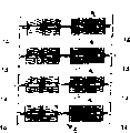
Aforesaid membrane filter housings is generally known in actual applications.In these prior art membrane filter housings, a plurality of membrane modules are placed in the housing like this, so that they are in the direction of mutual extension basically on flow direction.This housing is shown in Figure 1.Can clearly be seen that the inlet that wherein is used for fluid to be filtered of above-mentioned known membrane filter housings and the place, two ends that is used for being connected of penetrating fluid outlet all being positioned at housing.
Yet these known housing have some shortcomings.At first be inequality by the film circulation of various different membrane modules in the housing.Allow charging enter housing 1 at label 2 places, and at label 3 places with permeate discharge.For filtration, therefore reinforced will by membrane module 4,4 ', 4 ", 4 are sent to central permeate conduit 5.As a result, the pressure at the feed side place is the highest near the I and minimum near II.Correspondingly, at penetrating fluid one side place, pressure is minimum near the I and the highest near II.(it is poor to see through mould, TMD), and equals feed pressure and deducts permeate counterpressure divided by the local pressure reduction on the film for the film circulation.Because the pressure loss, this TMD is obviously will be than big near II near the I.These pressure reduction are caused by the buffer brake decline institute that feed side in the molecular filter assembly and permeate side place take place.Because irregular film circulation,, and so will stand a bigger mechanical load so each connector assembly will be stained more damnably.Being placed in more, originally the film at center produces little effect to filtering.In addition, this irregular film circulation will cause the problem that not every membrane module all will be cleaned equally well in cleaning process.This productivity ratio to whole film filter has a kind of negative effect.
The purpose of this invention is to provide a kind of membrane filter housings through improvement, described membrane filter housings through improvement does not show above-mentioned shortcoming.Specific purposes of the present invention provide a kind of membrane filter housings with regular membrane flux through improvement.Last purpose of the present invention provides a kind of membrane filter housings, and above-mentioned membrane filter housings is to utilize these membrane filter housings to simplify a kind of structure and continuous operation of filter for installation.
To achieve these goals, the invention provides a kind of membrane filter housings in kind described in the preamble, and above-mentioned membrane filter housings is characterized in that: one of them of penetrating fluid outlet and feed entrance is positioned at a wherein end place of membrane filter housings at least, and wherein another to be positioned at be a position in the middle part of membrane filter housings basically.Have many advantages according to housing of the present invention.Most important advantage is a kind of uniform pressure reduction of feed side with respect to permeate side, and with housing in location independent.Another advantage is that the space between each feed pipe and the permeate conduits separates.
Can filter application with " dead end " well according to membrane filter housings of the present invention.If make starting point as getting in actual applications, all membrane modules all have a pressure drop that equates, then all component all has the identical film pressure that sees through, and therefore have identical film throughput.This provides a well-proportioned thruput for whole device.In addition in this case, all membrane modules will show the identical degree that stains.This means that each membrane module can easier cleaning.Additional advantage of the present invention is that the two is identical because the pressure reduction of feed side is compared with the pressure reduction of per-meate side, so the pressure loss no longer exerts an influence to the uneven distribution of film circulation on each single component.Therefore do not need to make the pressure loss of each single component to reduce to minimum.
The penetrating fluid outlet is positioned at the place, two ends if feed entrance is positioned at housing middle part, and it is also very simple that an extra connection be used to the to concentrate discharging of liquid stream then is set at the two ends of membrane filter housings.After this manner, equipment can be used very simply as " cross flow one " filter.Can very accurate adjusting see through film pressure like this.At the feed side place, the barometric gradient from feed entrance to the liquid outlet of concentrating can be regulated by the flow velocity of control feed side.At the per-meate side place, barometric gradient will be caused by a kind of local flow loss that takes place.Suitable adjusting flow velocity can make the barometric gradient at feed side place and the barometric gradient coupling at per-meate side place now.This will cause and see through the in a basic balance of film pressure on whole membrane filter housings.According to another embodiment, flow velocity is to regulate at the per-meate side place.This provides identical advantage.
Can certainly regulate the two flow velocity of feed side and per-meate side.
According to the first further preferred embodiment, it is characterized in that according to housing of the present invention: feed entrance is positioned at a position at molecular filter middle part, and the penetrating fluid outlet is positioned at the place, two ends of membrane filter housings.This is a kind of plain mode of realizing the various embodiments described above.
Another embodiment requires each feed entrance to be provided and to provide a penetrating fluid to export in a position that is the membrane filter housings middle part basically at the place, two ends of membrane filter housings.According to another embodiment, providing the liquid outlet of concentrating in a position that is the molecular filter middle part basically also is a kind of selection scheme.
The present invention also provides a kind of filter system, uses at least one according to membrane filter housings of the present invention in described filter system.Preferably utilize this filter system, in described filter system, use some according to membrane filter housings of the present invention.Each feed entrance can be connected on the shared feed pipe then like this, so that liquid stream is successively near each membrane filter housings.
Herein below with reference to the accompanying drawings to further illustrate the present invention.Above-mentioned each accompanying drawing is represented preferred embodiments more of the present invention, rather than limits the present invention with it.
Fig. 1 illustrates according to the described a kind of membrane filter housings of prior art.
Fig. 2-2D illustrates described a kind of membrane filter housings according to first embodiment.
Fig. 3 and 3A illustrate described a kind of membrane filter housings according to one second embodiment of the present invention.
Fig. 4 is illustrated in during the cleaning according to a kind of membrane filter housings of the present invention.
Fig. 1 illustrates according to the described a kind of membrane filter housings 1 of prior art.Outlet is connected 3 to the institute's charging that provides connection 2 with penetrating fluid.Fluid to be filtered flow through membrane module 4,4 ', 4 ", 4 , and by penetrating fluid outlet 5 dischargings.
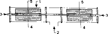
According to the present invention, first embodiment provides a kind of membrane filter housings as shown in Figure 2.Housing 1 comprise a plurality of assemblies 4,4 ', 4 " and 4 , and a central permeate conduit 5.Charging connects 2 by charging to be supplied with, and penetrating fluid is by penetrating fluid outlet 3 dischargings.Although permeate conduits 5 specifically is continuous, it can at random omit at position II place.When fluid to be filtered is supplied with at inlet 2 places, it with pass respectively membrane module 4 ' and 4, and 4 " and 4 arrive permeate conduits 5, and will connect 3 outflow housings by outlet subsequently.Filter because the result who sees through the mould difference between feed side and per-meate side realizes.Pressure reduction is a kind of driving force.Because the pressure loss in each membrane module, pressure is high near will be than I near the feed side II.Therefore, pressure will be than high near the I near the II in permeate conduits.This causes pressure reduction is constant in whole membrane filter housings scope basically.This provides a kind of very constant film circulation in whole membrane filter housings scope.
Fig. 2 A illustrates a kind of filter system, wherein the membrane filter housings shown in two Fig. 2 is linked together.Charging is supplied with by central feeding pipeline 6.Arrow A represents that charging passes through the flow direction of central feeding pipeline 6.Originally charging will arrive membrane filter housings 1 and the membrane filter housings 1 of arriving soon after '.Because feed rate is big near position 7 than near position 8, so that the diameter of feed pipe 6 preferably is designed in the position 7 places is bigger.If membrane filter housings 1 and 1 ' identical then is twice near near the flow velocity the position 7 generally will be than position 8.Therefore, near position 7, the diameter of feed pipe 6 is preferably also than so much greatly near the position 8, so that the feed flow constant airspeed.
Because generally on manufacturing technology, be difficult to provide and have the central feeding pipeline 6 different with membrane filter housings 1 diameter, so if membrane filter housings 1 is directly connected on the central feeding pipeline 6, shown in Fig. 2 A, then membrane filter housings was implemented shown in Fig. 2 B with being connected preferably of shared feed pipe 6.After this manner, very simple by desirable adjusting diameter.For example, can be as shown in Fig. 2 B, near the feed pipes the position 9 can be implemented the taper (not shown), be used for gradually from 7 ' neighbouring than major diameter be converted to 8 ' neighbouring than the minor diameter (not shown).
Certainly, only the invention is not restricted to two membrane filter housings 1,1 ' be combined into the filter system of a filter system, it also can make up more membrane filter housings, so that obtain a kind of filter system with many membrane filter housings.Fig. 2 C illustrates an embodiment, wherein 4 membrane filter housings is combined into a filter system.Yet in this case, it will particularly preferably be the diameter that makes shared feed conduit 6 and be suitable for inlet amount subject to the passing of its conduction, as shown in Fig. 2 B.
Fig. 2 D illustrates another embodiment of filter system shown in Fig. 2 C, and wherein " cross flow one " filtration is possible.Some extra connections 10 are set for this reason, above-mentioned connection 10 position membrane filter housings 1,1 ', 1 " and, place, 1 two ends.Supply with charging at feed entrance 2 places, above-mentioned charging by membrane module 4,4 ', 4 ", 4 add central permeate pipeline 5,5 ', 5 ", among 5 , above-mentioned membrane module 4,4 ', 4 ", 4 , be included in membrane filter housings 1,1 ', 1 ", in each of 1 .Permeate flow is to penetrating fluid outlet 3 subsequently.Membrane module 4 ' and 4 are flow through in charging respectively, and 4 " and 4 , and respectively 11,11 ' and near 12, the 12 ' conduct liquid discharging of concentrating.Charging can change by the flow velocity of membrane module.For this reason, for example, can perhaps plurality of valves be set at feed side 2 places at the liquid waste side place that concentrates.Alternatively, permeate flow can for example be controlled by the plurality of valves at permeate discharge side 3 places.Correctly control various liquid streams and make its barometric gradient on can control appliance.By control the flow velocity of charging and/or penetrating fluid with correct mode, can make the pressure drop on the entire equipment keep constant.After this manner, can obtain a kind of well-proportioned film circulation that sees through.
Fig. 3 illustrates another embodiment according to membrane filter housings of the present invention, and wherein feed entrance connects 2 places, two ends that are arranged on a membrane filter housings 1, and saturating liquid outlet 3 of filter is arranged on the middle part of membrane filter housings 1.Basically the molecular filter operation principle with Fig. 2 is identical according to the described membrane filter housings operation principle of Fig. 3.But the flow direction that flows through each membrane module is opposite.
According to another embodiment of the described membrane filter housings of Fig. 3 shown in Fig. 3 A.Embodiment shown in Fig. 3 A is suitable for cross flow one.Charging supply to membrane filter housings 1 by feed entrance 2 and flow through various housings 1,1 ', 1 ", the various membrane modules 4,4 of 1 ', 4 " and 4 , and as the liquid that concentrates by liquid delivery pipe 13 dischargings of concentrating of a center.As shown in Figure 3A, the center liquid delivery pipe 13 that concentrates also comprises a central permeate delivery pipe 14.This filters for cross flow one a kind of very compact structure is provided.The advantage is obtained with the method and pressure reduction can be adjusted to a steady state value.
Fig. 4 illustrates an embodiment, wherein just is rinsed according to the described filter plant of Fig. 2.For this reason, flushing water is supplied with near penetrating fluid outlet 3, flows through each membrane module 4 by permeate conduits 5, and by feed entrance 2 outflow equipment.System as shown in Figure 3 can clean by the recoil infiltration similarly.
And, it is obvious to the person skilled in the art that the direction of filtration can be opposite.In Fig. 1-3, filter and from inside to outside carry out.This means that charging is the place, inside at film, and penetrating fluid is in the outside.When filtration equipment is opposite, charging will be in the outside, and penetrating fluid is in place, inside (see figure 4).Zhuan Zhi cleaning will be carried out in the opposite direction then.
The invention is not restricted to the embodiment shown in each accompanying drawing.After having seen above-mentioned explanation, further modification will become apparent to one skilled in the art, and these all belong within protection scope of the present invention.For the purpose of safeguarding, it for example can be by opening the connection 14 shown in each accompanying drawing (seeing for example Fig. 2 C).Entire equipment can be for example by opening remaining connection in addition, or by local applied pressure, and be easy to emptying, above-mentioned local applied pressure can be for example realized by means of liquid or gas such as compressed air.
Claims (11)
1. membrane filter housings, comprise a kind of housing, described housing has a feed entrance, a penetrating fluid outlet and at least two molecular filters that are arranged in the housing, wherein a kind of fluid to be filtered is sent into molecular filter by feed entrance, and a kind of permeate flow is characterized in that by penetrating fluid outlet discharging: one of them of penetrating fluid outlet and feed entrance is positioned at an end place of membrane filter housings at least, and another to be positioned at be position in the middle part of membrane filter housings basically.
2. according to the described membrane filter housings of claim 1, it is characterized in that: feed entrance is positioned at position, membrane filter housings middle part, and each penetrating fluid outlet is positioned at the place, two ends of membrane filter housings.
3. according to the described membrane filter housings of claim 2, it is characterized in that: the liquid that respectively concentrates outlet is arranged near the two ends of membrane filter housings.
4. filter system, it is characterized in that: it comprises that at least one is according to one of them described membrane filter housings of aforesaid right requirement.
5. according to the described filter system of claim 4, it is characterized in that: it comprises according to claim 2 or 3 described several membrane filter housings, wherein each housing all makes a shared feeding tube be connected with each feed entrance, so that liquid stream is successively near each membrane filter housings.
6. according to the described filter system of claim 5, it is characterized in that: the diameter of shared feed conduit reduces towards flow direction.
7. according to the described filter system of claim 6, it is characterized in that: diameter reduces like this, so that liquid flow velocity to be filtered is constant basically in whole shared feed conduit.
8. according to the described membrane filter housings of claim 1, it is characterized in that: it is a position at the membrane filter housings middle part basically that some feed entrances are arranged on that the two ends place of membrane filter housings and penetrating fluid outlet be positioned at.
9. according to the described membrane filter housings of claim 8, it is characterized in that: it is a position at the membrane filter housings middle part basically that the liquid that concentrates outlet is positioned at.
10. filter system, it is characterized in that: described filter system comprises that at least one is according to claim 8 or 9 described membrane filter housings.
11. filter a kind of method of liquid, it is characterized in that: the method for a kind of liquid of described filtration is utilized and is a kind ofly required one of them described membrane filter housings according to aforesaid right.
Applications Claiming Priority (2)
| Application Number | Priority Date | Filing Date | Title |
|---|---|---|---|
| NL1019565A NL1019565C2 (en) | 2001-12-14 | 2001-12-14 | Membrane filter housing and method that it uses. |
| NL1019565 | 2001-12-14 |
Publications (1)
| Publication Number | Publication Date |
|---|---|
| CN1615174A true CN1615174A (en) | 2005-05-11 |
Family
ID=19774396
Family Applications (1)
| Application Number | Title | Priority Date | Filing Date |
|---|---|---|---|
| CN02827116.5A Pending CN1615174A (en) | 2001-12-14 | 2002-12-13 | Membrane filter housing and method of using the same |
Country Status (11)
| Country | Link |
|---|---|
| EP (1) | EP1458465B1 (en) |
| JP (1) | JP2005511296A (en) |
| CN (1) | CN1615174A (en) |
| AT (1) | ATE362393T1 (en) |
| AU (1) | AU2002353656B2 (en) |
| CA (1) | CA2472907C (en) |
| DE (1) | DE60220184T2 (en) |
| ES (1) | ES2284952T3 (en) |
| NL (1) | NL1019565C2 (en) |
| WO (1) | WO2003051497A1 (en) |
| ZA (1) | ZA200404664B (en) |
Cited By (4)
| Publication number | Priority date | Publication date | Assignee | Title |
|---|---|---|---|---|
| CN101985083A (en) * | 2010-10-26 | 2011-03-16 | 哈尔滨乐普实业发展中心 | Multi-film shell combining unit and multi-film shell combining method |
| WO2012055092A1 (en) * | 2010-10-26 | 2012-05-03 | 哈尔滨乐普实业发展中心 | Combination unit and combination method of multiple membrane shells |
| CN103118768A (en) * | 2010-07-30 | 2013-05-22 | X-流体公司 | A filtration method for operating a filtration module with gas feed at its permeate side to prevent backflow of permeate |
| CN108543424A (en) * | 2018-06-01 | 2018-09-18 | 南京九思高科技有限公司 | A kind of plate and frame infiltration vaporization membrane module having backwashing function |
Families Citing this family (9)
| Publication number | Priority date | Publication date | Assignee | Title |
|---|---|---|---|---|
| JP4531091B2 (en) * | 2004-04-22 | 2010-08-25 | ベカルト プログレッシブ コンポジッツ,リミテッド ライアビリティー カンパニー | Pressure vessel holding a cylindrical filtration cartridge |
| US7338601B2 (en) * | 2004-12-10 | 2008-03-04 | Uop Llc | Membrane separation assemblies |
| EP1937393A4 (en) * | 2005-08-22 | 2010-04-07 | Edmundo R Ashford | Compact membrane unit and methods |
| JP4918512B2 (en) * | 2008-02-26 | 2012-04-18 | 三菱重工業株式会社 | Method and apparatus for cleaning reverse osmosis membrane module |
| GB0808464D0 (en) * | 2008-05-09 | 2008-06-18 | H2Oil & Gas Ltd | Filtration system |
| US9608225B2 (en) | 2010-01-21 | 2017-03-28 | Samsung Electronics Co., Ltd. | Light emitting device and method of fabricating the same |
| EP2559477B1 (en) | 2011-08-15 | 2013-05-22 | TIG Automation GmbH | Device for filtering and separating flow media with hollow fibre membrane elements |
| WO2019066362A1 (en) * | 2017-09-29 | 2019-04-04 | 고려대학교 산학협력단 | Raw water distribution device connected to pressure vessel |
| KR102162759B1 (en) * | 2019-08-02 | 2020-10-07 | 효림산업주식회사 | Forward Osmosis Membrane Process |
Family Cites Families (15)
| Publication number | Priority date | Publication date | Assignee | Title |
|---|---|---|---|---|
| AU516562B2 (en) * | 1977-04-08 | 1981-06-11 | Dow Chemical Company, The | Hollow fibre separatory device |
| US4293419A (en) * | 1980-02-06 | 1981-10-06 | Toyo Boseki Kabushiki Kaisha | Hollow fiber membrane separation apparatus |
| JP3264007B2 (en) * | 1992-12-18 | 2002-03-11 | 栗田工業株式会社 | Spiral type membrane separation device |
| JPH07232037A (en) * | 1994-02-25 | 1995-09-05 | Hitachi Ltd | Membrane separation apparatus |
| NL1003309C1 (en) * | 1996-06-10 | 1996-07-24 | Rossmark Van Wijk En Boerma Wa | Membrane filter system and pressure vessel suitable for membrane filtration. |
| JP3900624B2 (en) * | 1997-11-05 | 2007-04-04 | 栗田工業株式会社 | Membrane separator |
| JPH11207153A (en) * | 1998-01-26 | 1999-08-03 | Kurita Water Ind Ltd | Membrane separator |
| JP4599633B2 (en) * | 1999-04-15 | 2010-12-15 | 栗田工業株式会社 | Membrane separator |
| JP2001137672A (en) * | 1999-11-18 | 2001-05-22 | Toray Ind Inc | Reverse osmosis treatment device and water making method |
| JP2001219038A (en) * | 2000-02-09 | 2001-08-14 | Kurita Water Ind Ltd | Membrane separator |
| ES2171146B1 (en) * | 2001-01-19 | 2003-12-16 | Membrane Concepts S L | SYSTEM FOR FILTERING FLUIDS, AND FILTER USED IN THIS PROCEDURE. |
| ES1048685Y (en) * | 2001-01-19 | 2002-02-01 | Membrane Concepts S L | CONNECTION OF THE EXTREME HEADS TO THE FILTER BODY |
| US20020074277A1 (en) * | 2000-11-24 | 2002-06-20 | Membrane Concepts, S.L. | Filter assembly, system and method for filtering fluids |
| ES1047914Y (en) * | 2000-11-24 | 2001-10-16 | Membrane Concepts S L | CONNECTION OF THE EXTREME HEADS TO THE MEMBRANE FILTER BODY. |
| ES1047795Y (en) * | 2000-11-24 | 2001-10-01 | Membrane Concepts S L Y En Su | BODY FOR MEMBRANE FILTERS. |
-
2001
- 2001-12-14 NL NL1019565A patent/NL1019565C2/en not_active IP Right Cessation
-
2002
- 2002-12-13 EP EP02789012A patent/EP1458465B1/en not_active Expired - Lifetime
- 2002-12-13 JP JP2003552420A patent/JP2005511296A/en active Pending
- 2002-12-13 AU AU2002353656A patent/AU2002353656B2/en not_active Ceased
- 2002-12-13 WO PCT/NL2002/000830 patent/WO2003051497A1/en active IP Right Grant
- 2002-12-13 CN CN02827116.5A patent/CN1615174A/en active Pending
- 2002-12-13 AT AT02789012T patent/ATE362393T1/en not_active IP Right Cessation
- 2002-12-13 ES ES02789012T patent/ES2284952T3/en not_active Expired - Lifetime
- 2002-12-13 CA CA2472907A patent/CA2472907C/en not_active Expired - Fee Related
- 2002-12-13 DE DE60220184T patent/DE60220184T2/en not_active Expired - Lifetime
-
2004
- 2004-06-11 ZA ZA2004/04664A patent/ZA200404664B/en unknown
Cited By (6)
| Publication number | Priority date | Publication date | Assignee | Title |
|---|---|---|---|---|
| CN103118768A (en) * | 2010-07-30 | 2013-05-22 | X-流体公司 | A filtration method for operating a filtration module with gas feed at its permeate side to prevent backflow of permeate |
| CN103118768B (en) * | 2010-07-30 | 2015-05-13 | X-流体公司 | A filtration method for operating a filtration module with gas feed at its permeate side to prevent backflow of permeate |
| CN101985083A (en) * | 2010-10-26 | 2011-03-16 | 哈尔滨乐普实业发展中心 | Multi-film shell combining unit and multi-film shell combining method |
| WO2012055092A1 (en) * | 2010-10-26 | 2012-05-03 | 哈尔滨乐普实业发展中心 | Combination unit and combination method of multiple membrane shells |
| CN101985083B (en) * | 2010-10-26 | 2014-09-03 | 哈尔滨乐普实业发展中心 | Multi-film shell combining unit and multi-film shell combining method |
| CN108543424A (en) * | 2018-06-01 | 2018-09-18 | 南京九思高科技有限公司 | A kind of plate and frame infiltration vaporization membrane module having backwashing function |
Also Published As
| Publication number | Publication date |
|---|---|
| NL1019565C2 (en) | 2003-06-17 |
| AU2002353656A1 (en) | 2003-06-30 |
| DE60220184T2 (en) | 2008-02-07 |
| JP2005511296A (en) | 2005-04-28 |
| CA2472907C (en) | 2011-09-20 |
| WO2003051497A1 (en) | 2003-06-26 |
| EP1458465B1 (en) | 2007-05-16 |
| DE60220184D1 (en) | 2007-06-28 |
| ZA200404664B (en) | 2005-11-30 |
| ATE362393T1 (en) | 2007-06-15 |
| ES2284952T3 (en) | 2007-11-16 |
| EP1458465A1 (en) | 2004-09-22 |
| AU2002353656B2 (en) | 2008-02-14 |
| CA2472907A1 (en) | 2003-06-26 |
Similar Documents
| Publication | Publication Date | Title |
|---|---|---|
| CN1615174A (en) | Membrane filter housing and method of using the same | |
| US4988445A (en) | Spiral wound filtration system and method of utilizing same | |
| CN101438091B (en) | Gas supply unit and gas supply system | |
| WO2004078306A3 (en) | Fluid separation and delivery apparatus and method | |
| EP2701822B1 (en) | Manifold arrangement, filter arrangement, and methods of bulk fluid filtration | |
| CN105813718A (en) | Self-supporting structure for membrane crossflow cartridges | |
| EP3922335A3 (en) | A filter element and a filter assembly | |
| CA3121455A1 (en) | A filter device, and method of assembly | |
| JP5014141B2 (en) | Method for filtering material containing particles in a suspension or solution in a fluid | |
| CN216377699U (en) | Full-automatic ultrafiltration equipment | |
| WO2005081627A2 (en) | Crossflow filtration system and method for membrane fouling prevention | |
| SK83296A3 (en) | Process and device for concentrating solid/liquid mixture by means of diaphragm technology and device for carrying out this method | |
| CN2587852Y (en) | Super filtering apparatus for automatic sewage treatment | |
| WO2002006028A3 (en) | Filtration system utilizing a single valve to direct fluid streams between filter assemblies and corresponding methods | |
| EP3925934A1 (en) | Liquid purification system | |
| CN109226113B (en) | Hydraulic pipeline flushing oil supply channel and flow control method thereof | |
| KR930006396B1 (en) | Serial crossflow filtration assembly | |
| CN1216674C (en) | Hollow fibre membrane separation equipment and its operation method | |
| EP1631369B1 (en) | Pump-pressure-exchanger system for reverse osmosis processes | |
| CN1480247A (en) | Membrane separation device composed of multiple groups of membrane module and its operating method | |
| CA2490906C (en) | Device for cross-flow filtration | |
| KR20200066570A (en) | System and method for filtering water | |
| CN214809883U (en) | Sewage membrane treatment system | |
| WO2022181541A1 (en) | Concentration device | |
| CN219824231U (en) | Sorting consumable pipe group and sorting equipment |
Legal Events
| Date | Code | Title | Description |
|---|---|---|---|
| C06 | Publication | ||
| PB01 | Publication | ||
| C10 | Entry into substantive examination | ||
| SE01 | Entry into force of request for substantive examination | ||
| C12 | Rejection of a patent application after its publication | ||
| RJ01 | Rejection of invention patent application after publication |