CN1573455B - Liquid crystal dispensing system using spacer information and method of dispensing liquid crystal material using the same - Google Patents
Liquid crystal dispensing system using spacer information and method of dispensing liquid crystal material using the same Download PDFInfo
- Publication number
- CN1573455B CN1573455B CN2004100499764A CN200410049976A CN1573455B CN 1573455 B CN1573455 B CN 1573455B CN 2004100499764 A CN2004100499764 A CN 2004100499764A CN 200410049976 A CN200410049976 A CN 200410049976A CN 1573455 B CN1573455 B CN 1573455B
- Authority
- CN
- China
- Prior art keywords
- liquid crystal
- piston
- substrate
- discharge pump
- crystal material
- Prior art date
- Legal status (The legal status is an assumption and is not a legal conclusion. Google has not performed a legal analysis and makes no representation as to the accuracy of the status listed.)
- Active
Links
Images


Classifications
-
- G—PHYSICS
- G02—OPTICS
- G02F—OPTICAL DEVICES OR ARRANGEMENTS FOR THE CONTROL OF LIGHT BY MODIFICATION OF THE OPTICAL PROPERTIES OF THE MEDIA OF THE ELEMENTS INVOLVED THEREIN; NON-LINEAR OPTICS; FREQUENCY-CHANGING OF LIGHT; OPTICAL LOGIC ELEMENTS; OPTICAL ANALOGUE/DIGITAL CONVERTERS
- G02F1/00—Devices or arrangements for the control of the intensity, colour, phase, polarisation or direction of light arriving from an independent light source, e.g. switching, gating or modulating; Non-linear optics
- G02F1/01—Devices or arrangements for the control of the intensity, colour, phase, polarisation or direction of light arriving from an independent light source, e.g. switching, gating or modulating; Non-linear optics for the control of the intensity, phase, polarisation or colour
- G02F1/13—Devices or arrangements for the control of the intensity, colour, phase, polarisation or direction of light arriving from an independent light source, e.g. switching, gating or modulating; Non-linear optics for the control of the intensity, phase, polarisation or colour based on liquid crystals, e.g. single liquid crystal display cells
- G02F1/133—Constructional arrangements; Operation of liquid crystal cells; Circuit arrangements
- G02F1/1333—Constructional arrangements; Manufacturing methods
- G02F1/1341—Filling or closing of cells
- G02F1/13415—Drop filling process
Landscapes
- Physics & Mathematics (AREA)
- Nonlinear Science (AREA)
- Mathematical Physics (AREA)
- Chemical & Material Sciences (AREA)
- Crystallography & Structural Chemistry (AREA)
- General Physics & Mathematics (AREA)
- Optics & Photonics (AREA)
- Liquid Crystal (AREA)
- Coating Apparatus (AREA)
- Application Of Or Painting With Fluid Materials (AREA)
Abstract
The invention relates to a liquid crystal distribution system, comprising a liquid crystal distributor and a control unit; wherein, the liquid distributor comprises a container for holding the liquid crystal material, a discharging pump is provided with a hydraulic cylinder with a suction opening and a discharging opening, and the discharging pump is inserted into the hydraulic cylinder, so as to sucks in and discharges out the liquid crystal inside the container respectively through the sucking opening and the discharging opening, the discharged liquid crystal material from the discharging pump is distributed on a base plate through a nozzle; the control unit calculates the liquid crystal material amount to distribute on the base plate based on the padding height formed on the base plate, controls the discharging pump, and distributes the calculated liquid crystal amount on the base plate; the image padding is formed during TFT working process or color filter working process, a plurality of liquid crystal display panels with different sizes are made on the base plate, the liquid crystal amount of the corresponding liquid display panel is calculated based on the height of padding on each liquid crystal display panel.
Description
Technical field
The present invention relates to LCD distribution system, be specifically related to and on the display panels that forms on the multi-mode glass substrate, distribute the LCD distribution system of accurate liquid crystal quantity and with the method for this system assignment liquid crystal material by using the wadding information setting liquid crystal sendout that forms on the substrate with different size.
Background technology
In recent years,, developed various portable electron devices because portable electron device has little, the in light weight and advantage of low energy consumption of volume, for example, mobile phone, PDA(Personal Digital Assistant) and notebook computer etc.Therefore, for example developed: LCD (LCD), plasma scope (PDP), Field Emission Display (FED) and vacuum fluorescent display panel display apparatus such as (VFD).In these panel display apparatus, because LCD has simple drive pattern and excellent images quality and produced in large quantity at present.
Fig. 1 shows the cut-open view of the LCD device of prior art.In Fig. 1, liquid crystal indicator 1 comprises: infrabasal plate 5, upper substrate 3 and the liquid crystal layer 7 that forms between upper and lower base plate.Infrabasal plate 5 is drive unit array base paltes, comprises a plurality of pixel (not shown) and the drive unit that is formed on each pixel, for example, and thin film transistor (TFT) (TFT).Upper substrate 3 is colour filtering chip basic boards, comprises the color filter layer that reproduces true colors.In addition, pixel electrode and common electrode are respectively formed on infrabasal plate 5 and the upper substrate 3.All be formed with oriented layer on upper substrate 3 and the infrabasal plate 5, so that the liquid crystal molecular orientation of liquid crystal layer 7.
Infrabasal plate 5 and upper substrate 3 usefulness sealants 9 are in the same place along perimeter bond, and liquid crystal layer 7 is limited in the periphery.In addition, make the liquid crystal molecule reorientation of liquid crystal layer 7, see through the light quantity of liquid crystal layer 7 with control by the drive unit that forms on the infrabasal plate 5, thus display image.
Fig. 2 shows the manufacture method process flow diagram of the liquid crystal indicator of prior art.In Fig. 2, manufacture method comprises three sub-operations making liquid crystal indicator: the drive unit array base palte operation that forms drive unit on infrabasal plate 5; On upper substrate 3, form the colour filtering chip basic board operation of color filter; The liquid crystal cell operation.
In step S101,, on infrabasal plate 5, form many gate lines and many data lines with the qualification pixel region, and on each pixel region, form the thin film transistor (TFT) that is connected to gate line and data line by drive unit array operation.In addition, form the pixel electrode be connected to thin film transistor (TFT), with according to driving liquid crystal layer through the thin film transistor (TFT) signal supplied by drive unit array operation.
In step S104, on upper substrate 3, form R (red), G (green) and B (orchid) color filter layer and the public electrode of reproducing color therewith by the color filter operation.
In step S102 and S105, on infrabasal plate 5 and upper substrate 3, form oriented layer.Then, independent rubbing alignment layer is so that the surface anchoring of the liquid crystal molecule of liquid crystal layer 7 (surface anchoring) (that is, pre-tilt angle and aligning direction).
In step S103, on infrabasal plate 5, wadding is set, be used between infrabasal plate 5 and upper substrate 3, keeping the box gap of uniformity.
In step S106, along the outside printing and sealing agent of upper substrate 3.
In step S107, infrabasal plate 5 and upper substrate 3 are assembled together by exerting pressure.
Infrabasal plate 5 and upper substrate 3 are all formed by glass substrate, comprise the display board district, a plurality of unit that forms drive unit and color filter layer on it.
In step S108, top glass substrate 3 and the lower glass substrate 3 that is assembled together cut into a plurality of unit display board.
In step S109, liquid crystal material is injected into by the liquid crystal filling orifice in the gap that forms between upper substrate 3 and the infrabasal plate 5, then, and with encapsulant encapsulated liquid crystals filling orifice.
In step S110, the unit display panel after liquid crystal material and the sealing has been filled in test.
Fig. 3 shows the synoptic diagram of liquid crystal injection systems of the manufacturing liquid crystal indicator of prior art.In Fig. 3, the container 12 of interior dress liquid crystal material 14 is put into vacuum chamber 10, and display panels 1 is placed on the top of container 12.Then, vacuum chamber 10 is connected to the vacuum pump (not shown), makes to keep predetermined vacuum tightness/pressure in the vacuum chamber.In addition, display panels mobile device (not shown) is contained in the vacuum chamber 10, in order to display panels 1 is moved to the surface of liquid crystal material 14 from the top of container 12, makes the filling orifice 16 contact liquid crystal materials 14 of display panels 1 thus.Therefore, the so-called liquid crystal of this method immersion method.
Filling orifice 16 at display panels 1 contacts under the state of liquid crystal materials 14, by flowing into nitrogen (N to vacuum chamber 10
2) when vacuum chamber 10 interior vacuum tightness/pressure are reduced, be injected into display panels 1 through filling orifice 16 by the pressure official post liquid crystal material 14 between the vacuum tightness/pressure in vacuum tightness/pressure in the display panels 1 and the vacuum chamber 10.Liquid crystal material 14 is injected into after the display panels 1 fully, with sealant sealing filling orifice 16, liquid crystal material 14 is sealed in the display panels 1.Therefore, this method is called the vacuum method for implanting.
But there are some shortcomings in above-mentioned liquid crystal immersion method and/or vacuum method for implanting.
At first, 14 injection 1 needed T.T.s of display panels of liquid crystal material are long.Usually, drive unit array base palte and the gap thickness between the colour filtering chip basic board in the display panels 1 are narrow, and for example, gap thickness has only several microns.Therefore, time per unit has only more a spot of liquid crystal material 14 to inject display panels 1.For example, need be with just finishing the work that liquid crystal material 14 injects one 15 inches display panels in 8 hours, therefore, it is low to make efficient.
The second, the consumption of liquid crystal material 14 increases in liquid crystal injecting method.In container 12, have only a spot of liquid crystal material 14 actual display panels 1 that are injected into.Therefore, in the process of vacuum chamber 10 that display panels 1 is packed into, otiose liquid crystal material 14 exposes in atmosphere or some gas, and liquid crystal material 14 is polluted.Therefore, after liquid crystal material 14 is injected into a plurality of display panels 1, must abandon remaining liquid crystal material 14, thereby cause production cost to increase.
Summary of the invention
The objective of the invention is, provide a kind of liquid crystal material directly is assigned on the large-area glass substrate that comprises at least one display panels LCD distribution system and with the method for this system assignment liquid crystal material.
Another object of the present invention is, a kind of LCD distribution system is provided, described device calculates the sendout of liquid crystal according to the height of the wadding that forms on the substrate, all the time distribute accurate amount of liquid crystal thus, prevent to produce bum liquid crystal indicator and with the method for this system assignment liquid crystal material.
Another purpose of the present invention is, provide on a kind of substrate that accurate amount of liquid crystal can be assigned to display panels with a plurality of different sizes LCD distribution system and with the method for its dispensing liquid crystal material.
In order to obtain these and other advantages of the present invention, according to purpose of the present invention, in this description as concrete and broad sense, a kind of LCD distribution system provided by the invention comprises liquid crystal dispensing apparatus and control module, wherein, described liquid crystal dispensing apparatus is made up of following these parts: the container of interior dress liquid crystal; The hydraulic cylinder of band material sucking port and discharge gate, it is installed in the hydraulic cylinder; Be used for sucking and discharging is contained in the discharge pump of the liquid crystal material of container by moving up and down through material sucking port and discharge gate; Be assigned to nozzle on the substrate with the liquid crystal material that is used for to give off from discharge pump, described control module is according to the liquid crystal material sendout that is assigned at the wadding high computational needs that form on the substrate on the substrate, and control discharge pump, thus liquid crystal material is assigned on the substrate, wherein said discharge pump comprises a hydraulic cylinder; Insert hydraulic cylinder and at the reeded piston in certain zone of its underpart, described piston is by rotation and move up and down and suck and the discharging liquid crystal material; And the material sucking port and the discharge gate that are used for when piston moves, correspondingly sucking and discharging liquid crystal.
Operation in front, just thin mould transistor operation or color filter operation form and measure wadding, described wadding is colored wadding or composition wadding, thus with measurement result by wired or wireless mode Input Control Element.
According to another technical scheme of the present invention, LCD distribution system comprises liquid crystal dispensing apparatus and control module.Described liquid crystal dispensing apparatus is by constituting with lower member: the container of interior dress liquid crystal, be provided with piston and suck and discharging is contained in the discharge pump of the liquid crystal in the container and will be assigned to nozzle on the multi-mode substrate of its a plurality of display panels that are formed with different size from the liquid crystal that discharge pump gives off by moving up and down of piston.The wadding high computational that described control module forms according to the display panels place at substrate is assigned to the amount of liquid crystal on a plurality of display panels, the control discharge pump, order assignment liquid crystal material on a plurality of display panels thus, wherein said discharge pump comprises a hydraulic cylinder; Insert hydraulic cylinder and at the reeded piston in certain zone of its underpart, described piston is by rotation and move up and down and suck and the discharging liquid crystal material; And the material sucking port and the discharge gate that are used for when piston moves, correspondingly sucking and discharging liquid crystal.
In order to obtain these advantages of the present invention and other advantages, as concrete and broadly described, also provide a kind of distribution method of liquid crystal material here, may further comprise the steps: the step of the wadding height that forms on the input substrate; To be distributed in the step of the amount of liquid crystal on the substrate according to the wadding high computational; Aim at the step of liquid crystal dispensing apparatus, described liquid crystal dispensing apparatus is by constituting with lower member: the container of interior dress liquid crystal, have piston and nozzle by distribution locations on the moving up and down discharge pump that suction/discharging is contained in the liquid crystal in the container and will be assigned to its multi-mode substrate that is formed with the different display panels of a plurality of sizes of piston from the liquid crystal that discharge pump gives off, wherein said discharge pump comprises a hydraulic cylinder, insert hydraulic cylinder and at the reeded piston in certain zone of its underpart, described piston is by rotation and move up and down suction and the discharging liquid crystal material, and the material sucking port and the discharge gate that are used for correspondingly sucking and discharging liquid crystal when piston moves; And the amount of liquid crystal that calculates is assigned to step on the substrate.
By the detailed description of doing below in conjunction with accompanying drawing, can understand above-mentioned purpose, feature and advantage with other of the present invention better.
Description of drawings
Included being used to provide further understood and the accompanying drawing that constitutes an instructions part that included shows each embodiment of the present invention the present invention, and is used for explaining principle of the present invention together with explanatory note.
In these accompanying drawings:
Fig. 1 shows the cut-open view of the liquid crystal indicator (LCD) of prior art;
Fig. 2 shows the LCD device preparation method process flow diagram of prior art;
Fig. 3 shows the synoptic diagram of liquid crystal injection systems that is used to make liquid crystal indicator of prior art;
Fig. 4 shows the cut-open view of using the liquid crystal indicator of making according to liquid crystal distributing method of the present invention;
Fig. 5 shows the LCD device preparation method process flow diagram with liquid crystal distributing method;
Fig. 6 shows the ultimate principle figure of liquid crystal distributing method;
Fig. 7 shows the skeleton view according to liquid crystal dispensing apparatus of the present invention;
Fig. 8 shows the decomposition diagram according to liquid crystal dispensing apparatus of the present invention;
Fig. 9 A shows the skeleton view according to the liquid crystal discharge pump of liquid crystal dispensing apparatus of the present invention;
Fig. 9 B shows the decomposition diagram of liquid crystal discharge pump;
Figure 10 shows the synoptic diagram of the liquid crystal discharge pump that is fixed to fixed cell;
Figure 11 A shows the application drawing of liquid crystal discharge pump to 11D;
Figure 12 shows the synoptic diagram of the liquid crystal discharge pump of fixed angles increase;
Figure 13 shows the block diagram according to the control module of LCD distribution system of the present invention;
Figure 14 shows the block diagram according to electric-motor drive unit of the present invention;
Figure 15 shows according to liquid crystal distributing method process flow diagram of the present invention.
Embodiment
In detail referring to the preferred embodiments of the present invention, some examples of embodiment show in the accompanying drawings now.
In order to overcome the shortcoming that exists in the available liquid crystal method for implanting such as liquid crystal immersion method or liquid crystal vacuum method for implanting for example, recently, liquid crystal drip-injection method has been proposed.Described liquid crystal drip-injection method is directly to be instilled into liquid crystal on the substrate, in the substrate assembling process, two substrates are pressed together and make instillation to whole display panel, form the method for liquid crystal layer, rather than liquid crystal is injected into the method in the unit display board of sky with the inside and outside pressure differential of display panel in the dispersed liquid crystal on the substrate.According to above-mentioned liquid crystal drip-injection method, liquid crystal directly is instilled in the time cycle of a weak point on the substrate, forms the liquid crystal layer in the large area liquid crystal display device rapidly.In addition, because the liquid crystal of direct instillation aequum, so, make the consumption of liquid crystal reach minimum, therefore, reduced production cost.
Fig. 4 shows the ultimate principle according to liquid crystal distributing method of the present invention.In Fig. 4, before infrabasal plate 105 that drive unit will be arranged and the upper substrate 103 that color filter is arranged are assembled together, liquid crystal material 107 is instilled on the infrabasal plate 105.Perhaps, liquid crystal material 107 is instilled on the upper substrate 103 that is formed with color filter on it.For example, liquid crystal material 107 can formed on thin film transistor (TFT) (TFT) substrate or on color filter (CF) substrate.
Along the neighboring part encryption envelope agent 109 of upper substrate 103 at least.Then, upper substrate 103 and infrabasal plate 105 are exerted pressure it is assembled together form display panels 101.And by affacting the pressure on upper substrate 103 and/or the infrabasal plate 105, the dropping point of liquid crystal material 107 disperses between upper substrate 103 and infrabasal plate 105, forms the liquid crystal material layer of thickness uniformity thus between upper substrate 103 and infrabasal plate 105.Therefore, in exemplary LCD device preparation method of the present invention, upper substrate 103 and infrabasal plate 105 be assembled together form display panels 101 before, liquid crystal material 107 is instilled on the infrabasal plate 105.
Fig. 5 shows according to exemplary LCD device preparation method process flow diagram of the present invention.In step S201, drive unit, for example thin film transistor (TFT) (TFT) is formed on the upper substrate with the tft array operation.
In step S204, on infrabasal plate 105, form color filter layer with the color filter operation, similar with those general operations, TFT matrix operation and color filter operation preferably are used on the glass substrate with a plurality of unit display panel areas.Here, upper substrate and infrabasal plate comprise having about 1000 * 1200mm
2Or more large-area glass substrate.But, also can be with glass substrate with less area.
In step S202 and S205, on upper and lower base plate, all form oriented layer and rub.
In step S203, liquid crystal material 107 is instilled on the liquid crystal display panel zone of infrabasal plate 105.
In step S206, on the subregion of outer peripheral portion at least of the liquid crystal display panel zone of upper substrate, add sealant 109.
In step S207, upper substrate and infrabasal plate are arranged to face mutually, and upper substrate and infrabasal plate are exerted pressure, and with sealant it are assembled together.Therefore, the liquid crystal material of instillation can be evenly dispersed between upper substrate, infrabasal plate and the sealant.
In step S208, upper substrate that has been assembled together and infrabasal plate cut into a plurality of liquid crystal display plates through handling.
In step S209, test liquid crystal display plate.
Have any different at the aspects such as processing time of the injection of liquid crystal vacuum, liquid crystal drip-injection and large-area glass substrate with the LCD device preparation method of liquid crystal drip-injection method shown in Figure 5 and LCD device preparation method with the liquid crystal vacuum method for implanting of prior art.That is to say that in the manufacture method with the liquid crystal indicator of liquid crystal injecting method shown in Figure 2, liquid crystal injects through filling orifice, then, seals filling orifice with sealant.But in using the LCD device preparation method of liquid crystal drip-injection method, liquid crystal directly is instilled on the substrate, does not need the sealing process of filling orifice.Although in Fig. 2, do not show,, with in the LCD device preparation method of liquid crystal injecting method, when injecting liquid crystal, the substrate contacts liquid crystal, so, therefore the outside surface of display panel can be needed cleaning process to clean contaminated substrate by liquid crystal pollution.But in using the LCD device preparation method of liquid crystal drip-injection method, liquid crystal directly is instilled on the substrate, so therefore display panel can not needed the board cleaning operation by liquid crystal pollution.LCD device preparation method with liquid crystal drip-injection method is simpler than the LCD device preparation method with liquid crystal injecting method, therefore, can enhance productivity and product percent of pass.
In the LCD device preparation method with liquid crystal drip-injection method, the instillation position of liquid crystal and the dropped amount of liquid crystal have a significant impact the formation of liquid crystal layer with definite thickness.Specifically, because the box gap of the thickness of liquid crystal layer and display panels is closely related, accurate liquid crystal drip-injection position and accurate liquid crystal drop fluence are of crucial importance for preventing to produce bum display panels.For accurate amount of liquid crystal being instilled into accurate position, the invention provides a kind of liquid crystal dispensing apparatus.
Fig. 6 shows the manufacture method skeleton view according to another exemplary liquid crystal indicator of the present invention.In Fig. 6, liquid crystal material 107 is assigned on the glass substrate 105 with the liquid crystal dispensing apparatus 120 that is positioned at glass substrate 105 tops.Although do not show among the figure,, liquid crystal material 107 is contained in the liquid crystal dispensing apparatus 120.
When liquid crystal material 107 was instilled on the glass substrate 105, glass substrate 105 moved along X-direction and Y-direction according to predetermined speed, and simultaneously, liquid crystal dispensing apparatus 120 discharges liquid crystal material 107 at interval according to preset time.Therefore, be instilled into liquid crystal material 107 on the glass substrate 105 by predetermined interval along with glass substrate distributes along moving of X-direction and Y-direction.Perhaps, glass substrate 105 is fixing, and liquid crystal dispensing apparatus 120 moves along X-direction and Y-direction, presses preset time dispenser method material 107 at interval.But any vibration of liquid crystal dispensing apparatus 120 all can change the shape of liquid crystal material 107, thereby, the instillation site error and the dropped amount error of liquid crystal material 107 can appear.So, preferably fixedly liquid crystal dispensing apparatus 120 and mobile glass substrate 105.
Fig. 7 shows the skeleton view according to liquid crystal dispensing apparatus of the present invention, and Fig. 8 shows the decomposition diagram according to liquid crystal dispensing apparatus of the present invention.In Fig. 7 and Fig. 8, liquid crystal dispensing apparatus 120 comprises the cylindrical liquid crystal material container 122 that is installed in the shell 123.Cylindrical liquid crystal material container 122 usefulness tygon are made, and liquid crystal material 107 is contained in the liquid crystal material container 122.Shell 123 usefulness stainless steels are made, and liquid crystal material container 122 wherein is installed.Because tygon has high-ductility, so form the liquid crystal material container of required form easily with tygon.And when container 122 was equipped with liquid crystal material 107, tygon can not react with liquid crystal material 107, and therefore, tygon is to be mainly used in the material of making liquid crystal material container 122.But poly intensity is low, easy deformation when being added with stress.During 122 distortion of liquid crystal material container, liquid crystal material 107 just can not accurately be assigned on the substrate.Therefore, liquid crystal material container 122 should be installed to and have in the shell 123 that high-intensity stainless steel makes.
Although do not show among the figure,, can air supply pipe be set on the top of liquid crystal material container 122, so that supply with for example inert gas of nitrogen.Gas is supplied with in the liquid crystal material container 122 not by in occupied that part of liquid crystal material 107.Thus, by gas exerting pressure of liquid crystal material 107 is assigned to liquid crystal material 107 on the substrate.
Liquid crystal material container 122 can comprise indeformable material, for example, and stainless steel.Therefore, when making liquid crystal material container 122, just do not need shell 123, thereby reduced the manufacturing cost of liquid crystal material container 122 with stainless steel.The inside of liquid crystal material container 122 can apply a fluororesin, to prevent to be contained in the sidewall generation chemical reaction of liquid crystal material 107 and liquid crystal material container 122 in the liquid crystal material container 122.
In the bottom of liquid crystal material container 122 liquid crystal emptying pump 140 is set.Liquid crystal emptying pump 140 is used for discharging liquid crystal containers 122 certain amount of liquid crystal, makes liquid crystal drip-injection to substrate.Liquid crystal emptying pump 140 is provided with the liquid crystal material sucking port 147 that is connected to liquid crystal material container 122, when operation liquid crystal emptying pump 140, be used to draw liquid crystal material, relative edge at liquid crystal material sucking port 147 forms liquid crystal discharge gate 148, when operation liquid crystal emptying pump 140, is used to discharge liquid crystal material.
In Fig. 8, first connecting pipe 126 is connected to liquid crystal material material sucking port 147.Although can liquid crystal material material sucking port 147 be connected to first connecting pipe 126 with the inserted mode that shows in the accompanying drawing, but, also can liquid crystal material material sucking port 147 be connected to first connecting pipe 126, form for example pin 128 of the inner injection pin type that penetrates on one side of first connecting pipe 126 with coupling arrangements such as for example screws.Be provided with the liner made from the material with highly shrinkable and high leakproofness of for example silicon rubber or the formation of butyl type rubber material (not showing) in the bottom of liquid crystal material container 122, be used for liquid crystal material is discharged into first connecting pipe 126.Pin 128 passes liner and inserts liquid crystal material container 122, thus the liquid crystal material in the liquid crystal material container 122 107 is incorporated into liquid crystal material material sucking port 147.When pin 128 inserted in the liquid crystal material container 122, pin 128 shrank liner greatly, prevents that thus liquid crystal material 107 from leaking into the insertion district of pin 128.Because liquid crystal material material sucking port 147 and liquid crystal material container 122 usefulness pins and liner interconnect, so syndeton is simple, connect easily/unclamp.
The liquid crystal material sucking port 147 and first connecting pipe 126 can constitute a unit.In this case, the pin 128 that forms at liquid crystal material sucking port 147 places directly inserts liquid crystal material container 122, discharges liquid crystal thus, thereby has simple structure.
Second connecting pipe 160 can be made with opaque material.But, owing to following reason will be made second connecting pipe 160 with transparent material.
During dispenser method, contain steam in the liquid crystal material 107, thereby the accurate sendout of the liquid crystal material 107 of Control Allocation to the substrate.Therefore, steam will be removed when the dispenser method material.Steam has been included in the liquid crystal material 107 of the liquid crystal material container 122 of will packing into.Promptly use the vapour removal device can remove the steam that is included in the liquid crystal material 107, can not remove devaporation fully.And, when introducing liquid crystal emptying pump 140, liquid crystal material container 122 also can produce steam at liquid crystal material 107.Therefore, can not remove the steam that is included in the liquid crystal material 107 fully.So the best method of removing devaporation is a shut-down operation liquid crystal dispensing apparatus when producing steam.
The reason of making second connecting pipe 160 with transparent material is: the steam in order easily to find to comprise or produce in the liquid crystal material container 122 prevents bum liquid crystal indicator.Steam can use user's naked eyes to find, and can detect automatically with the first sensor 162 that for example optocoupler that is installed in second connecting pipe, 160 both sides adds up to, and wherein latter event can prevent bum liquid crystal indicator better.
The nozzle 150 of introducing the liquid crystal that discharges through second connecting pipe 160 is provided with protected location 152, is subjected to the effect of external carbuncle to prevent two side surfaces of nozzle 150.And; whether second sensor, 154, the second sensors 154 are set at protected location 152 places that are positioned at nozzle 150 bottoms is used for detecting the liquid crystal material that gives off from nozzle 150 and whether comprises steam or be used to detect assemble on the surface of nozzle 150 liquid crystal material is arranged.
The lip-deep phenomenon that liquid crystal material accumulates in nozzle 150 has stoped accurate dispenser method material 107.During by nozzle 150 dispenser method materials,, also there is the certain amount of liquid crystal material to be dispersed on the surface of nozzle 150 even give off the amount of liquid crystal that sets in advance from liquid crystal discharge pump 140.Therefore, the liquid crystal material amount that is assigned on the substrate is less than the amount of liquid crystal that sets in advance.And, when the lip-deep liquid crystal material that accumulates in nozzle 150 is instilled on the substrate, can produce bum liquid crystal indicator.In order to prevent that liquid crystal material from accumulating on the surface of nozzle 150, can be with dipping method or spraying method deposit on the surface of nozzle 150 hydrophobic materials such as fluororesin of high contact angle are for example arranged with liquid crystal.By the deposit fluororesin, liquid crystal material can not be dispersed on the surface of nozzle 150, and liquid crystal material 107 can be assigned on the substrate through nozzle 150 with good dropping point shape.
Liquid crystal discharge pump 140 is inserted in the rotary part 157, and rotary part 157 is fixed to fixed cell 155.Rotary part 157 is connected to first motor 131.During first machine operation, rotary part 157 rotations, the liquid crystal discharge pump 140 that is fixed to rotary part 157 is worked.
Liquid crystal discharge pump 140 contacts with one side of shaft-like liquid crystal material volume controlled element 134.The another side of shaft-like liquid crystal material volume controlled element 134 forms the hole, in turning axle 136 patchholes.Form screw thread in the hole of liquid crystal material volume controlled element 134 and the periphery of turning axle 136, the hole of liquid crystal material volume controlled element 134 is connected with the spiral bind mode mutually with turning axle 136.One end of turning axle 136 is connected to second motor 133, and the other end of turning axle 136 is connected to control lever 137.
Change along with the variation of the fixed angles of 140 pairs of rotary parts 157 of liquid crystal discharge pump from the liquid crystal material amount that liquid crystal material container 122 gives off through liquid crystal discharge pump 140.That is to say that the liquid crystal material capacity of liquid crystal discharge pump 140 changes along with the variation of the fixed angles of 140 pairs of rotary parts 157 of liquid crystal discharge pump.When driving is connected to second motor 133 of turning axle 136 (control automatically), perhaps, during 137 work of control lever (manually control), turning axle 136 rotations.For this reason, the end liquid crystal material volume controlled element 134 that is connected to turning axle 136 with drive screw moves forward and backward (by rectilinear direction) along turning axle 136.And when an end of liquid crystal material volume controlled element 134 moved, the power that is added on the liquid crystal discharge pump 140 changed, and therefore, the fixed angles of liquid crystal discharge pump 140 changes.
As above-mentioned, first motor, 131 operation liquid crystal discharge pumps 140, therefore, the liquid crystal material 107 that liquid crystal material container 122 is discharged is instilled on the substrate.And 133 controls of second motor are fixed to the fixed angles of the liquid crystal discharge pump 140 of rotary part 157, control thus from the liquid crystal material amount of liquid crystal discharge pump 140 dischargings.
The amount of liquid crystal that once is instilled on the substrate through liquid crystal discharge pump 140 is very little, and is also very little with the variable quantity of the liquid crystal discharge pump 140 of second motor 133 control.Therefore, in order to control the discharge capacity of liquid crystal discharge pump 140, the pitch angle of liquid crystal discharge pump 140 also will be controlled very for a short time.In order to carry out little control, the servomotor of usefulness pulse input quantity operation or stepper motor are as second motor 133.
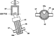
Fig. 9 A shows the skeleton view of liquid crystal discharge pump, and Fig. 9 B shows the decomposition diagram of liquid crystal discharge pump.
In Fig. 9 A and Fig. 9 B, liquid crystal discharge pump 140 comprises: the shell 141 that has liquid crystal material sucking port 147 and liquid crystal discharge gate 148; At its top opening is arranged and be connected to the lid 144 of shell 141; Insert the hydraulic cylinder 142 that is used to suck liquid crystal in the shell 141; Be used for the packoff 143 of sealing liquid cylinder pressure 142; Be arranged on and be used to above the lid 144 prevent that the O-shape that liquid crystal leaks from encircling 144a; Can move up and down and rotate the piston 145 that is used for sucking and discharging liquid crystal material that inserts hydraulic cylinder 142 through lid 144 by liquid crystal material sucking port 147 and liquid crystal discharge gate 148.The piston head 146a that is fixed to rotary part 157 is inserted into above the piston 145, and bar 146b is inserted on the piston head 146a.Bar 146b is inserted in the hole (not having picture) of rotary part 157 and is fixing, and when 131 reinforcings of first motor made rotary part 157 rotations, piston 145 rotated thus.
In Fig. 9 B, at the end formation groove 145a of piston 145.The area of groove 145a is equivalent to 1/4 long-pending (or littler) of circular cross section of piston 145.During piston 145 rotations (that is, moving up and down), groove 145a switch liquid crystal material sucking port 147 and liquid crystal discharge gate 148 suck and the discharging liquid crystal material by liquid crystal material sucking port 147 and liquid crystal discharge gate 148 thus.
The below operation of explanation liquid crystal discharge pump 140.
Figure 10 shows the view of the liquid crystal discharge pump 140 that is fixed to rotary part 157.In Figure 10, piston 145 is fixed to rotary part 157 by certain angle (α).The bar 146b that forms at piston head 146a place inserts the hole 159 that rotary part 157 the insides form, so piston 145 and rotary part 157 interconnect.Although do not show,, the inside of 159 is provided with bearing in the hole, and the bar 146b of the piston 145 of patchhole 159 can all around be moved.During 131 work of first motor, rotary part 157 rotations make piston 145 rotations that are connected to rotary part 157 thus.
Here, if the liquid crystal discharge pump is fixed to the fixed angles (α) of rotary part 157, promptly piston 145 is fixed to the fixed angles (α) of rotary part 157, is 0 degree, and so, 145 in piston rotatablely moves along rotary part 157.But, because the fixed angles (α) of piston 145 is not O degree (that is to say that piston 145 is by certain fixed angle), so piston not only rotates along rotary part 157, and can also move up and down.
If piston 145 rotates a certain angle and moves up, so, in hydraulic cylinder 142, form the space, liquid crystal sucks this space by liquid crystal material sucking port 147.Then, if piston 145 rotates and moves down, the liquid crystal material in the inhalant liquid cylinder pressure 142 is by 148 dischargings of liquid crystal discharge gate so.Here, when rotary-piston 145 sucks and discharges liquid crystal, groove 145a switch liquid crystal material sucking port 147 and liquid crystal discharge gate 148 that piston 145 places form.
Below be described in more detail the operation of liquid crystal discharge pump 140 to 11D referring to Figure 11 A.
In 11D, the liquid crystal material 107 of liquid crystal discharge pump 140 in 4 stroke discharging liquid crystal containers 122 is to nozzle 150 at Figure 11 A.Figure 11 A and Figure 11 C show quadrature (cross) stroke, and Figure 11 B shows the intake stroke by liquid crystal material sucking port 147, and Figure 11 D shows the discharge stroke by liquid crystal discharge gate 148.
In Figure 11 A, the piston 145 that is fixed to rotary part 157 by certain angle (α) rotates along with the rotation of rotary part 157.At this moment, piston 145 is closed liquid crystal material sucking port 147 and liquid crystal discharge gate 148.
As shown in Figure 11 B, during the about miter angle of rotary part 157 rotation, piston 145 rotations, the groove 145a of piston 145 opens liquid crystal material sucking port 147.The bar 146B of piston 145 inserts in the hole 159 of rotary part 157, is thus connected rotary part 157 and piston 145.Therefore, piston 145 rotates along with rotary part 157 rotations.At this moment, bar 146b rotates along a Plane of rotation.
Because piston 145 is fixed to rotary part 157 by certain angle (α), bar 146b rotates along Plane of rotation, so piston 145 moves up along with rotary part 157 rotations.And, fix owing to be positioned at the hydraulic cylinder 142 of piston 145 bottoms, along with the rotation of rotary part 157, in hydraulic cylinder 142, form a space.Thereby liquid crystal sucks in the space by the liquid crystal material sucking port of opening with groove 145a 147.
Intake stroke (that is to say, liquid crystal material sucking port 147 is opened) beginning after, described liquid crystal material intake stroke is proceeded, till along with quadrature stroke (that is to say that the liquid crystal material sucking port 147 is closed) beginning shown in the about miter angle of rotary part 157 rotations, Figure 11 C.
Then, shown in Figure 11 D, along with rotary part 157 rotates again, liquid crystal discharge gate 148 is opened, and piston 145 moves down, and the liquid crystal material in the space of 142 li formation of inhalant liquid cylinder pressure is by 148 dischargings (discharge stroke) of liquid crystal discharge gate.
As above-mentioned, liquid crystal discharge pump 140 repeats 4 strokes, that is, the first quadrature stroke, intake stroke, second quadrature stroke and the discharge stroke are discharged into nozzle 150 with the liquid crystal material in the liquid crystal material container 122 107 thus.
Here, the liquid crystal material discharge capacity changes according to the scope of moving up and down of piston 145.The scope that moves up and down of piston 145 is along with the angle that rotary part 157 is fixed to liquid crystal discharge pump 140 changes and changes.
Figure 12 shows the liquid crystal discharge pump and is fixed to synoptic diagram on the rotary part by the β angle.Compare with the liquid crystal discharge pump 140 that is fixed to rotary part 157 by the α angle shown in Figure 10, shown in Figure 12 (the liquid crystal discharge pump 140 that the angle of β>α) is fixed to rotary part 157 makes piston 145 De Genggao that moves up by β.That is to say that the angle of liquid crystal discharge pump 140 that is fixed to rotary part 157 is big more, the amount of the liquid crystal material 107 of inhalant liquid cylinder pressure 142 was many more when piston 145 moved.This means that the angle that is fixed to the liquid crystal discharge pump 140 of rotary part 157 by adjusting can be controlled the discharge capacity of liquid crystal material 107.
Be fixed to the angle of the liquid crystal discharge pump 140 of rotary part 157 by liquid crystal material volume controlled element shown in Figure 7 134 control, by second motor, 133 mobile liquid crystal material capacity control elements 134.That is to say, control the angle of the liquid crystal discharge pump 140 that is fixed to rotary part 157 by controlling second motor 133.
By user's adjusting angle control lever 137 can manual adjustments liquid crystal discharge pump 140 fixed angles.But under this situation, the impossible time of accurately regulating and need be a large amount of, the driving of liquid crystal discharge pump 140 can stop in operating process.Thereby, the fixed angles that the most handy second motor 133 is regulated liquid crystal discharge pump 140.
Measure the fixed angles of liquid crystal discharge pump 140 with the sensor 139 of for example linear variable differential converter.If the fixed angles of liquid crystal discharge pump 140 is greater than predetermined angle, sensor 139 is reported to the police so, prevents that liquid crystal discharge pump 140 from damaging.
Although do not illustrate, in fact first motor 131 and second motor 133 are to be connected to a control module by wireless or wired mode.Calculating will be assigned to the liquid crystal material amount of display panels to control every kind of device thereby various information are input to control module.
The height correlation of liquid crystal material sendout and wadding.In relevant liquid crystal vacuum method for implanting, mainly use the globe lining bedding and padding.But, in liquid crystal distributing method, mainly use composition wadding or column wadding, its reason is as follows: as above-mentioned, liquid crystal distributing method is mainly used in makes the large-area liquid crystal display panel.If large-area liquid crystal display panel globe lining bedding and padding then are difficult to make the globe lining bedding and padding to be evenly dispersed on the substrate, the globe lining bedding and padding that disperseed accumulate on the substrate, thereby the box gap that causes display panels is with low quality.For this reason, in liquid crystal distributing method, form composition wadding (pattern spacer) in the precalculated position and solve this problem.
Under the height of the actual composition wadding that the is formed at colour filtering chip basic board situation different with the box gap that sets in advance, even predefined amount of liquid crystal is assigned to (because the box gap is different with the height of the actual composition wadding that forms) on the substrate, the amount of liquid crystal that comprises in the actual display panels that forms is also different with best amount of liquid crystal.The amount of liquid crystal of supposing actual allocated is less than best amount of liquid crystal, for example, under the situation of the black mode liquid crystal indicator of routine, can have problems in shiny black degree, under the situation of the white mode liquid crystal indicator of routine, can have problems in white luminance.
On the contrary, when supposing actual liquid crystal sendout, can produce gravity defect when making display panels greater than best amount of liquid crystal.When making display panels, because temperature raises, the volume of the inner liquid crystal layer that forms of display panels can increase, thereby produces gravity defect.For this reason, the box gap of display panels becomes greater than wadding, thereby liquid crystal moves down under action of gravity, causes the box gap of display panels inhomogeneous, thereby has damaged the quality of liquid crystal indicator.
Control module is not according to predefined box gap but calculates the liquid crystal sendout according to the wadding height of actual measurement.
Input wadding height when the wadding in TFT operation or color filter operation forms operation.That is to say, in wadding forms operation, form wadding and measure the height of wadding, to supply with control module.Wadding forms production line and distributes production line to separate with liquid crystal.For this reason, measured wadding height is by wired or wireless mode Input Control Element.And, with the height of independent operation measurement wadding.For example, form the operation production line (promptly at wadding, TFT operation production line or color filter operation production line) and liquid crystal distribute and between the production line wadding height measuring device to be set and to measure the wadding height, measured wadding height is input to liquid crystal and distributes production line.
In Figure 13, control module 200 comprises: wadding height input media 210 is used for importing the wadding height that records by wired or wireless mode in TFT operation production line or color filter operation production line; Input media 220 is used to import various information, for example, and the area of the quantity of the display surface plate that will form on the area of substrate, the substrate, the position of display panel, display panel, the kind of liquid crystal material, viscosity of liquid crystal material or the like; Liquid crystal sendout calculation element 230 is used for according to the height of the composition wadding of importing from wadding height input media 210 and the various information of importing from input media 220, and calculating will be assigned to the liquid crystal sendout on the display panels; Motor driver 240 is used to operate second motor 133, with liquid crystal material sendout of discharging calculating and the fixed angles of controlling liquid crystal discharge pump 140; Substrate drive unit 250 is used for driving substrate, makes liquid crystal dispensing apparatus move to the original allocation position of corresponding display panels thus; Output unit 260, be used to export various information, the quantity of the display panels sheet that for example, forms on the substrate, the size of the current display panels that will distribute, to be assigned to amount of liquid crystal on the corresponding display panels and current liquid crystal distributive condition.
Liquid crystal sendout calculation element 230 calculates the amount of liquid crystal that will be assigned on the display panels according to the size of display panels, the height of composition wadding and the characteristic information of liquid crystal.That is to say, to form thereon under the situation of glass substrate unit of a plurality of display panels, liquid crystal sendout calculation element 230 does not calculate the liquid crystal sendout, and under the situation of display panels unit, liquid crystal sendout calculation element 230 calculates the liquid crystal sendout.
As above-mentioned, according to the present invention, under the situation of display panels unit, calculate the liquid crystal sendout, therefore, can form on the multi-mode glass substrate of a plurality of display panels of different size dispensing liquid crystal effectively thereon.Owing to form a plurality of display panels of different size on the multi-mode glass substrate, so, can improve the efficient of glass substrate, reduce production costs thus.If a plurality of display panels that form on the glass substrate have different box gaps (promptly, the height difference of each wadding), owing to be assigned to amount of liquid crystal on each display panels according to the wadding high computational, therefore, the present invention can be on the multi-mode glass substrate dispensing liquid crystal effectively.
In Figure 14, motor driver 240 comprises: pulse value memory storage 244 is used to store the pulse value information relevant with the liquid crystal sendout, to drive first motor 131 and second motor 133; Pulse value conversion equipment 242 according to the pulse value information of storage in the pulse value memory storage 244, will convert pulse value to from the liquid crystal sendout of liquid crystal sendout calculation element 230 inputs; First motor driver 246, the drive signal of output correspondence when the liquid crystal sendout input of calculating drives first motor 131, operation liquid crystal discharge pump 140 thus; Second electric-motor drive unit 248, the drive signal of correspondence drove second motor 133 thus when the pulse value of output after 242 conversions of pulse value converting unit imported, and changed the fixed angles of liquid crystal discharge pump 140.
Store a large amount of rotary angle information of second motor 133 relevant in the pulse value storage unit 244 with pulse value.Therefore, during the input pulse value, second motor 133 correspondingly rotates corresponding angle, simultaneously, inserts liquid crystal material volume controlled element 134 linear the moving of turning axle 136.Finally, by moving of liquid crystal material volume controlled element 134, change fixed angles, thereby change from the amount of liquid crystal of liquid crystal discharge pump 140 dischargings with respect to the liquid crystal discharge pump 140 of fixed cell 149.
As above-mentioned, second motor 133 is stepper motors, and when about 1000 pulses of input, 133 rotations of second motor once.That is to say that a pulse makes about 0.36 degree of second motor, 133 rotations.Therefore, the anglec of rotation of second motor 133 can be accurately controlled, thereby the amount of liquid crystal of liquid crystal discharge pump 140 dischargings can be accurately controlled with pulse.
Figure 15 shows a kind of method with wadding height dispensing liquid crystal material.Though liquid crystal distributing method shown in Figure 15 is to be used on the multi-mode glass substrate, liquid crystal distributing method also can be used on the monotype glass substrate.
As shown in figure 15, the input glass substrate, this glass substrate comprises a plurality of display panels that size is different, forms TFT or color filter (step S301) in TFT operation production line or color filter operation production line.Here, the various information relevant with substrate and display panels, for example, information such as the coordinate of the quantity of the size of substrate, display panels sheet, the size of each display panels, display panels and original allocation position are input to the control module 200 of liquid crystal dispensing apparatus.And, the characteristic information of liquid crystal, for example, the kind of liquid crystal and the viscosity of liquid crystal is Input Control Element 200 also.Here, liquid crystal information, information substrate and display panels information can directly be imported by the user, also can import by reading relevant identification code, and these identification codes for example are bar code that forms on the glass substrate and the information that comprises.
Control module 200 is wanted the coordinate and the size of the display panels of dispensing liquid crystal according to the information check of input, to discern the display panels (step S302) of correspondence.
In TFT operation production line or color filter operation production line, on substrate, form the composition wadding, and measure the composition wadding height (step S303) of wanting Input Control Element 200.
Then, control module 200 is according to the various information and the wadding high computational liquid crystal sendout (step S304) that will be assigned to each display panels of input, and driving substrate makes liquid crystal dispensing apparatus 120 aim at the initial position of the display panels of dispensing liquid crystal thereon.Although do not show, because motor makes substrate move along X-axis and Y direction, therefore, drive motor makes substrate move to the distribution locations of display panels.Here, also can make liquid crystal dispensing apparatus 120 aim at the original allocation position of display panels by directly driving liquid crystal dispensing apparatus rather than driving substrate.
As above-mentioned, under the state of the distribution locations of liquid crystal dispensing apparatus 120 align substrates, carry out liquid crystal distribute (step S305, S306).Here, the pulse value converting unit 242 of electric-motor drive unit 240 is calculated the pulse value of the corresponding liquid crystal sendout of being calculated, and drives second motor 133 thus, regulates the fixed angles of liquid crystal discharge pump 140.Therefore, the work liquid crystal along with first motor 131 is assigned on the display panels.
Be assigned on the corresponding display panels next piece display panels (step S307) that control module 200 identifications will distribute, the calculation process of repetition liquid crystal sendout if finished liquid crystal.That is to say that therefore wadding height that forms on the display panels of control module 200 according to correspondence and various information calculations liquid crystal sendout, are assigned to liquid crystal on the corresponding display panels.
As above-mentioned, according to the present invention, according to the sendout of the wadding high computational liquid crystal that forms in TFT operation production line or the color filter operation production line.For this reason, can prevent the inaccurate bum liquid crystal indicator (LCD) that causes of liquid crystal sendout.And according to the present invention, the liquid crystal sendout is calculated by the display panels unit, therefore, accurate liquid crystal sendout can be assigned on the multi-mode glass substrate.
Under the prerequisite that does not break away from spirit of the present invention or principal character; can implement the present invention with various ways; but; should be appreciated that; the above embodiments are not limited to above-mentioned any details and describe, unless other special provision is arranged, in the spirit and scope of the present invention that appended claims limits large-scale structure should be arranged; therefore, all changes and improvements and equivalents thereof that fall in the claimed scope of the application's appending claims all will belong to protection scope of the present invention.
Claims (31)
1. LCD distribution system comprises:
One container, interior dress liquid crystal;
One discharge pump is used for sucking the liquid crystal of adorning with discharging container;
One nozzle is used for the liquid crystal from the discharge pump discharging is assigned to substrate;
One control module is used for according to the wadding high computational liquid crystal sendout that forms on the substrate, and the control discharge pump is assigned to the liquid crystal sendout of calculating on the substrate thus,
Wherein said discharge pump is by constituting with lower member: a hydraulic cylinder; One piston; One rotary part; This piston is fixed on this rotary part, and inserts hydraulic cylinder, and is fluted in certain zone of its underpart, and this rotary part rotation causes this piston and the rotation of this groove and moves up and down, and makes groove suck and the discharging liquid crystal material by rotating and moving up and down; One material sucking port and a discharge gate are used for when piston moves, and correspondingly suck and discharge liquid crystal.
2. according to the LCD distribution system of claim 1, it is characterized in that, also comprise the fixedly fixed cell of discharge pump.
3. according to the LCD distribution system of claim 2, it is characterized in that fixed cell comprises rotary part, the piston of discharge pump is fixed on the rotary part, with rotary-piston.
4. according to the LCD distribution system of claim 3, it is characterized in that piston is provided with a bar, rotary part is provided with a hole, and when bar rotatably during patchhole, piston correspondingly is fixed to rotary part.
5. according to the LCD distribution system of claim 3, it is characterized in that, the liquid crystal capacity of discharge pump along with piston with respect to the change of the fixed angles of rotary part and change.
6. according to the LCD distribution system of claim 1, it is characterized in that, also comprise the liquid crystal material volume controlled element that contacts discharge pump, be used to change the fixed angles of discharge pump, control the liquid crystal discharge capacity thus.
7. according to the LCD distribution system of claim 6, it is characterized in that, also comprise:
Motor, be used to drive liquid crystal volume controlled element and
One turning axle is connected to liquid crystal material volume controlled element with the spiral bind mode, and correspondingly rotates when drive motor, thus in order to linear mobile liquid crystal material capacity control element.
8. according to the LCD distribution system of claim 7, it is characterized in that motor is a stepper motor.
9. according to the LCD distribution system of claim 1, it is characterized in that, also comprise:
One first connecting pipe is used to connect container and discharge pump;
One pin is inserted in an end of first connecting pipe, is inserted into thus in the liner that the container place forms, and pin inside penetrates, and is used for introducing the liquid crystal material of container.
10. according to the LCD distribution system of claim 1, it is characterized in that, also comprise:
One second connecting pipe is used to connect discharge pump and nozzle.
11. the LCD distribution system according to claim 10 is characterized in that, second connecting pipe constitutes with transparent material.
12. the LCD distribution system according to claim 11 is characterized in that, also comprises:
One first sensor is installed near second connecting pipe, is used for detecting the liquid crystal material that gives off from discharge pump and whether contains steam.
13. the LCD distribution system according to claim 1 is characterized in that, also comprises:
One second sensor is installed near the nozzle, is used to detect liquid crystal and whether accumulates in nozzle surface.
14. the LCD distribution system according to claim 1 is characterized in that, wadding is the composition wadding.
15. the LCD distribution system according to claim 1 is characterized in that, substrate comprises a plurality of display panels that size is different.
16. the LCD distribution system according to claim 15 is characterized in that, according to the wadding high computational liquid crystal sendout that forms on the display panels.
17. the LCD distribution system according to claim 1 is characterized in that, control module comprises:
One height input block, the height of the wadding that is used for forming on the input substrate;
One sendout computing unit is used to calculate the liquid crystal sendout that will be assigned on the substrate;
Electric-motor drive unit is used for drive motor, the operation discharge pump.
18. the LCD distribution system according to claim 17 is characterized in that, also comprises:
One substrate drive unit is used for driving substrate, thereby nozzle alignment is arrived the liquid crystal material distribution locations.
19., it is characterized in that electric-motor drive unit comprises according to claim 17 LCD distribution system:
One pulse value storage unit is used to store the pulse value information relevant with the liquid crystal sendout; With
One pulse value converting unit according to the pulse value information of storing in the pulse value storage unit, will convert pulse value to from the dispensed amount of sendout computing unit input.
20. a LCD distribution system comprises:
One liquid crystal dispensing apparatus, described liquid crystal dispensing apparatus is by constituting with lower member: the container of interior dress liquid crystal material; The hydraulic cylinder of band material sucking port and discharge gate; Insert hydraulic cylinder and the discharge pump that moves up and down the liquid crystal material of in material sucking port and discharge gate suction and discharging container, adorning; The liquid crystal of discharge pump discharging is assigned to nozzle on the substrate;
One control module will be assigned to amount of liquid crystal on the substrate according to the wadding high computational that forms on the substrate, the control discharge pump, thus liquid crystal is assigned on the substrate,
Wherein said discharge pump is by constituting with lower member: a hydraulic cylinder; One piston; One rotary part; This piston is fixed on this rotary part, and insertion hydraulic cylinder, certain zone in this piston bottom is fluted, and this rotary part rotation causes this piston and the rotation of this groove and moves up and down, and makes groove suck and the discharging liquid crystal material by rotating and moving up and down; One material sucking port and a discharge gate are used for when piston moves, and correspondingly suck and discharge liquid crystal.
21. a LCD distribution system comprises:
One liquid crystal dispensing apparatus, described liquid crystal dispensing apparatus is by constituting with lower member: the container of interior dress liquid crystal material; Discharge pump with piston moves up and down the liquid crystal of adorning in suction and the discharging container by piston; Nozzle, the liquid crystal material that discharge pump is given off are assigned on the multi-mode substrate of a plurality of display panels of different size;
One control module, the wadding high computational that forms on the display panels according to substrate will be assigned to the amount of liquid crystal on a plurality of display panels, control discharge pump, thereby with the liquid crystal order assignment to a plurality of display panels,
Wherein said discharge pump is by constituting with lower member: a hydraulic cylinder; One piston; One rotary part; This piston is fixed on this rotary part, and insertion hydraulic cylinder, certain zone in this piston bottom is fluted, and this rotary part rotation causes this piston and the rotation of this groove and moves up and down, and makes groove suck and the discharging liquid crystal material by rotating and moving up and down; One material sucking port and a discharge gate are used for when piston moves, and correspondingly suck and discharge liquid crystal.
22. a liquid crystal material distribution method may further comprise the steps:
The wadding height that forms on the input substrate;
To be assigned to amount of liquid crystal on the substrate according to the wadding high computational;
Aim at liquid crystal dispensing apparatus, described liquid crystal dispensing apparatus is by constituting with lower member: the container of interior dress liquid crystal material; Discharge pump with piston moves up and down the liquid crystal of adorning in suction/discharging container by piston; Nozzle, the liquid crystal material that discharge pump is given off at the distribution locations place are assigned on the multi-mode substrate of a plurality of display panels that different size is arranged on it, and wherein said discharge pump is by constituting with lower member: a hydraulic cylinder, a piston; One rotary part; This piston is fixed on this rotary part, and insertion hydraulic cylinder, certain zone in this piston bottom is fluted, this rotary part rotation causes this piston and the rotation of this groove and moves up and down, make groove suck and the discharging liquid crystal material by rotating and moving up and down, one material sucking port and a discharge gate are used for when piston moves, and correspondingly suck and discharge liquid crystal; The amount of liquid crystal that calculates is assigned on the substrate.
23. the method according to claim 22 is characterized in that, also comprises:
Drive the step of second motor, to regulate the fixed angles of discharge pump, the amount of liquid crystal that discharging is calculated.
24. the method according to claim 22 is characterized in that, the step that liquid crystal is assigned on the substrate comprises the step that drives the first motor operation piston.
25. the method according to claim 22 is characterized in that, also comprises:
Form the wadding on the substrate; With
Measure formed wadding height.
26. the method according to claim 25 is characterized in that, forms wadding in TFT operation or color filter operation.
27. the method according to claim 26 is characterized in that, measures the wadding height in TFT operation or color filter operation.
28. the method according to claim 22 is characterized in that, wadding is the composition wadding.
29. the method according to claim 22 is characterized in that, substrate comprises a plurality of display panels of different size.
30. the method according to claim 29 is characterized in that, the step of calculating the liquid crystal sendout comprises the step of the wadding high computational liquid crystal sendout that forms according to the display panels place at each different size.
31. a liquid crystal distributing method may further comprise the steps:
Preparation comprises the substrate of a plurality of display panels of different size;
The wadding height that forms on the input display panels;
To be assigned to amount of liquid crystal on the display panels according to the wadding high computational;
Aim at liquid crystal dispensing apparatus, described liquid crystal dispensing apparatus is by constituting with lower member: the container of interior dress liquid crystal material; Discharge pump with piston moves up and down the liquid crystal of adorning in suction/discharging container by piston; And nozzle, the liquid crystal material of discharge pump being discharged at the display panels distribution locations place of correspondence is assigned on the multi-mode substrate of a plurality of display panels that different size is arranged on it, and wherein said discharge pump is by constituting with lower member: a hydraulic cylinder, a piston; One rotary part; This piston is fixed on this rotary part, and insertion hydraulic cylinder, certain zone in this piston bottom is fluted, this rotary part parts rotation causes this piston and the rotation of this groove and moves up and down, make groove suck and the discharging liquid crystal material by rotating and moving up and down, one material sucking port and a discharge gate are used for when piston moves, and correspondingly suck and discharge liquid crystal;
The amount of liquid crystal that calculates is assigned on the substrate;
Aim at the distribution locations place that liquid crystal dispensing apparatus is wanted the next display panels of dispensing liquid crystal material on it.
Applications Claiming Priority (2)
| Application Number | Priority Date | Filing Date | Title |
|---|---|---|---|
| KR1020030041275A KR100566455B1 (en) | 2003-06-24 | 2003-06-24 | Liquid crystal dispensing system using spacer information and method of dispensing liquid crystal material using thereof |
| KR10-2003-0041275 | 2003-06-24 |
Publications (2)
| Publication Number | Publication Date |
|---|---|
| CN1573455A CN1573455A (en) | 2005-02-02 |
| CN1573455B true CN1573455B (en) | 2010-04-28 |
Family
ID=36959764
Family Applications (1)
| Application Number | Title | Priority Date | Filing Date |
|---|---|---|---|
| CN2004100499764A Active CN1573455B (en) | 2003-06-24 | 2004-06-23 | Liquid crystal dispensing system using spacer information and method of dispensing liquid crystal material using the same |
Country Status (7)
| Country | Link |
|---|---|
| US (1) | US7159624B2 (en) |
| JP (2) | JP2005018062A (en) |
| KR (1) | KR100566455B1 (en) |
| CN (1) | CN1573455B (en) |
| DE (1) | DE102004030135B4 (en) |
| FR (1) | FR2856612B1 (en) |
| TW (1) | TWI293261B (en) |
Families Citing this family (10)
| Publication number | Priority date | Publication date | Assignee | Title |
|---|---|---|---|---|
| CN100362399C (en) * | 2003-11-17 | 2008-01-16 | Lg.菲利浦Lcd株式会社 | Liquid crystal distributing method and device thereof |
| KR100987910B1 (en) * | 2003-11-28 | 2010-10-13 | 엘지디스플레이 주식회사 | An apparatus and method of dispensing liquid crystal |
| KR20060110936A (en) | 2005-04-20 | 2006-10-26 | 엘지.필립스 엘시디 주식회사 | Liquid crystal display device and method for manufacturing the same |
| KR101030529B1 (en) * | 2005-06-20 | 2011-04-26 | 엘지디스플레이 주식회사 | Method of manufacturing Liquid Crystal Display Device using the same |
| JP2007011164A (en) * | 2005-07-04 | 2007-01-18 | Nec Kagoshima Ltd | Method of manufacturing liquid crystal display panel by liquid crystal dropping lamination method, and liquid crystal dropping lamination device |
| KR101285034B1 (en) * | 2011-11-04 | 2013-07-10 | 한형수 | Cam type fluid dispenser |
| US9416776B2 (en) * | 2013-03-15 | 2016-08-16 | Siemens Healthcare Diagnostics Inc. | Microfluidic distributing device |
| CN109611309A (en) * | 2018-12-24 | 2019-04-12 | 广州市安亦捷自动化设备有限公司 | A kind of adjustable plunger pump |
| CN111249997B (en) * | 2020-03-31 | 2022-09-13 | 李翠芝 | High accuracy dropping funnel |
| CN113238414B (en) * | 2021-05-18 | 2024-02-02 | 深圳市宏显伟业科技有限公司 | LCD panel liquid crystal intelligent injection equipment and processing technology thereof |
Family Cites Families (81)
| Publication number | Priority date | Publication date | Assignee | Title |
|---|---|---|---|---|
| US3978580A (en) | 1973-06-28 | 1976-09-07 | Hughes Aircraft Company | Method of fabricating a liquid crystal display |
| JPS5165656A (en) | 1974-12-04 | 1976-06-07 | Shinshu Seiki Kk | |
| US4094058A (en) | 1976-07-23 | 1978-06-13 | Omron Tateisi Electronics Co. | Method of manufacture of liquid crystal displays |
| JPS5738414A (en) | 1980-08-20 | 1982-03-03 | Showa Denko Kk | Spacer for display panel |
| JPS5788428A (en) | 1980-11-20 | 1982-06-02 | Ricoh Elemex Corp | Manufacture of liquid crystal display body device |
| JPS5827126A (en) | 1981-08-11 | 1983-02-17 | Nec Corp | Production of liquid crystal display panel |
| JPS5957221A (en) | 1982-09-28 | 1984-04-02 | Asahi Glass Co Ltd | Production of display element |
| JPS59195222A (en) | 1983-04-19 | 1984-11-06 | Matsushita Electric Ind Co Ltd | Manufacture of liquid-crystal panel |
| JPS60111221A (en) | 1983-11-19 | 1985-06-17 | Nippon Denso Co Ltd | Method and device for charging liquid crystal |
| JPS60164723A (en) | 1984-02-07 | 1985-08-27 | Seiko Instr & Electronics Ltd | Liquid crystal display device |
| JPS60217343A (en) | 1984-04-13 | 1985-10-30 | Matsushita Electric Ind Co Ltd | Liquid crystal display device and its preparation |
| JPS617822A (en) | 1984-06-22 | 1986-01-14 | Canon Inc | Production of liquid crystal element |
| JPS6155625A (en) | 1984-08-24 | 1986-03-20 | Nippon Denso Co Ltd | Manufacture of liquid crystal element |
| WO1986006794A1 (en) * | 1985-05-10 | 1986-11-20 | Bergman, Manfred | Valve-free piston pump |
| US4775225A (en) | 1985-05-16 | 1988-10-04 | Canon Kabushiki Kaisha | Liquid crystal device having pillar spacers with small base periphery width in direction perpendicular to orientation treatment |
| US4575317A (en) * | 1985-06-26 | 1986-03-11 | M&T Chemicals Inc. | Constant clearance positive displacement piston pump |
| JP2535142B2 (en) | 1985-07-15 | 1996-09-18 | 株式会社 半導体エネルギー研究所 | Liquid crystal display device manufacturing method |
| JP2616761B2 (en) | 1985-07-15 | 1997-06-04 | 株式会社 半導体エネルギー研究所 | Method for manufacturing liquid crystal display device |
| JPS6254228A (en) | 1985-07-15 | 1987-03-09 | Semiconductor Energy Lab Co Ltd | Manufacturing method for liquid crystal display |
| US4691995A (en) | 1985-07-15 | 1987-09-08 | Semiconductor Energy Laboratory Co., Ltd. | Liquid crystal filling device |
| JPS6289025A (en) | 1985-10-15 | 1987-04-23 | Matsushita Electric Ind Co Ltd | Liquid crystal display panel and its production |
| JPS6290622A (en) | 1985-10-17 | 1987-04-25 | Seiko Epson Corp | Liquid crystal display device |
| US4941809A (en) * | 1986-02-13 | 1990-07-17 | Pinkerton Harry E | Valveless positive displacement metering pump |
| US4653864A (en) | 1986-02-26 | 1987-03-31 | Ovonic Imaging Systems, Inc. | Liquid crystal matrix display having improved spacers and method of making same |
| JPH0668589B2 (en) | 1986-03-06 | 1994-08-31 | キヤノン株式会社 | Ferroelectric liquid crystal element |
| US5379139A (en) | 1986-08-20 | 1995-01-03 | Semiconductor Energy Laboratory Co., Ltd. | Liquid crystal device and method for manufacturing same with spacers formed by photolithography |
| US5963288A (en) | 1987-08-20 | 1999-10-05 | Semiconductor Energy Laboratory Co., Ltd. | Liquid crystal device having sealant and spacers made from the same material |
| JPS63109413A (en) | 1986-10-27 | 1988-05-14 | Fujitsu Ltd | Production of liquid crystal display |
| JPS63110425A (en) | 1986-10-29 | 1988-05-14 | Toppan Printing Co Ltd | Cell for sealing liquid crystal |
| JPS63128315A (en) | 1986-11-19 | 1988-05-31 | Victor Co Of Japan Ltd | Liquid crystal display element |
| JPS63311233A (en) | 1987-06-12 | 1988-12-20 | Toyota Motor Corp | Liquid crystal cell |
| DE3825066A1 (en) | 1988-07-23 | 1990-01-25 | Roehm Gmbh | METHOD FOR PRODUCING THICKNESS, ANISOTROPIC LAYERS ON SURFACE-STRUCTURED CARRIERS |
| US4964078A (en) | 1989-05-16 | 1990-10-16 | Motorola, Inc. | Combined multiple memories |
| JPH0536425A (en) | 1991-02-12 | 1993-02-12 | Tokyo Electric Power Co Inc:The | Alloy separator for solid electrolytic fuel cell and manufacture of the same |
| DE69226998T2 (en) | 1991-07-19 | 1999-04-15 | Sharp Kk | Optical modulation element and devices with such an element |
| JP3068264B2 (en) | 1991-07-31 | 2000-07-24 | 三菱重工業株式会社 | Solid electrolyte fuel cell |
| JPH05107533A (en) | 1991-10-16 | 1993-04-30 | Shinetsu Eng Kk | Method and device for sticking glass substrate for liquid crystal display plate |
| JPH05127179A (en) | 1991-11-01 | 1993-05-25 | Ricoh Co Ltd | Production of liquid crystal display element |
| JP2609386B2 (en) | 1991-12-06 | 1997-05-14 | 株式会社日立製作所 | Board assembly equipment |
| JP3159504B2 (en) | 1992-02-20 | 2001-04-23 | 松下電器産業株式会社 | Liquid crystal panel manufacturing method |
| DE4207318A1 (en) * | 1992-03-08 | 1993-09-09 | Zipperer M Cat Ingbuero | Acid-resistant laboratory metering pump - has two piston-type rotary valve pump units arranged in parallel and phase-displaced by 180 deg. |
| JPH05265011A (en) | 1992-03-19 | 1993-10-15 | Seiko Instr Inc | Production of liquid crystal display element |
| JPH05281562A (en) | 1992-04-01 | 1993-10-29 | Matsushita Electric Ind Co Ltd | Manufacture of liquid crystal panel |
| JP2939384B2 (en) | 1992-04-01 | 1999-08-25 | 松下電器産業株式会社 | Liquid crystal panel manufacturing method |
| US5507323A (en) | 1993-10-12 | 1996-04-16 | Fujitsu Limited | Method and dispenser for filling liquid crystal into LCD cell |
| JP2604090B2 (en) | 1992-06-30 | 1997-04-23 | 信越エンジニアリング株式会社 | Glass substrate bonding equipment for liquid crystal display panels |
| JPH0651256A (en) * | 1992-07-30 | 1994-02-25 | Matsushita Electric Ind Co Ltd | Device for discharging liquid crystal |
| JPH0664229A (en) | 1992-08-24 | 1994-03-08 | Toshiba Corp | Optical printing head |
| JP3084975B2 (en) | 1992-11-06 | 2000-09-04 | 松下電器産業株式会社 | Liquid crystal display cell manufacturing equipment |
| JPH06160871A (en) | 1992-11-26 | 1994-06-07 | Matsushita Electric Ind Co Ltd | Liquid crystal display panel and its production |
| JPH06194637A (en) | 1992-12-24 | 1994-07-15 | Shinetsu Eng Kk | Method for sticking glass substrate for liquid crystal display plate |
| JP3210126B2 (en) | 1993-03-15 | 2001-09-17 | 株式会社東芝 | Manufacturing method of liquid crystal display device |
| US5539545A (en) | 1993-05-18 | 1996-07-23 | Semiconductor Energy Laboratory Co., Ltd. | Method of making LCD in which resin columns are cured and the liquid crystal is reoriented |
| JP2957385B2 (en) | 1993-06-14 | 1999-10-04 | キヤノン株式会社 | Manufacturing method of ferroelectric liquid crystal device |
| CA2108237C (en) | 1993-10-12 | 1999-09-07 | Taizo Abe | Method and dispenser for filling liquid crystal into lcd cell |
| JP2864447B2 (en) | 1994-05-31 | 1999-03-03 | 株式会社東京機械製作所 | Printing machine pump |
| US5854664A (en) | 1994-09-26 | 1998-12-29 | Matsushita Electric Industrial Co., Ltd. | Liquid crystal display panel and method and device for manufacturing the same |
| JP3216869B2 (en) | 1995-02-17 | 2001-10-09 | シャープ株式会社 | Liquid crystal display device and method of manufacturing the same |
| US6001203A (en) | 1995-03-01 | 1999-12-14 | Matsushita Electric Industrial Co., Ltd. | Production process of liquid crystal display panel, seal material for liquid crystal cell and liquid crystal display |
| JPH0980447A (en) | 1995-09-08 | 1997-03-28 | Toshiba Electron Eng Corp | Liquid crystal display element |
| JP3358935B2 (en) | 1995-10-02 | 2002-12-24 | シャープ株式会社 | Liquid crystal display device and method of manufacturing the same |
| US6236445B1 (en) | 1996-02-22 | 2001-05-22 | Hughes Electronics Corporation | Method for making topographic projections |
| KR100208475B1 (en) | 1996-09-12 | 1999-07-15 | 박원훈 | Method for lc alignment layer with magnetic field process |
| EP0829748A3 (en) | 1996-09-13 | 1999-12-15 | Sony Corporation | Reflective guest-host liquid-crystal display device |
| JPH10153785A (en) | 1996-09-26 | 1998-06-09 | Toshiba Corp | Liquid crystal display device |
| KR100207506B1 (en) | 1996-10-05 | 1999-07-15 | 윤종용 | Lcd device manufacturing method |
| JP3472422B2 (en) | 1996-11-07 | 2003-12-02 | シャープ株式会社 | Liquid crystal device manufacturing method |
| JPH10274768A (en) | 1997-03-31 | 1998-10-13 | Denso Corp | Liquid crystal cell and its manufacture |
| JP4028043B2 (en) | 1997-10-03 | 2007-12-26 | コニカミノルタホールディングス株式会社 | Liquid crystal light modulation device and method for manufacturing liquid crystal light modulation device |
| US5875922A (en) | 1997-10-10 | 1999-03-02 | Nordson Corporation | Apparatus for dispensing an adhesive |
| US6055035A (en) | 1998-05-11 | 2000-04-25 | International Business Machines Corporation | Method and apparatus for filling liquid crystal display (LCD) panels |
| US6337730B1 (en) | 1998-06-02 | 2002-01-08 | Denso Corporation | Non-uniformly-rigid barrier wall spacers used to correct problems caused by thermal contraction of smectic liquid crystal material |
| JP3828670B2 (en) | 1998-11-16 | 2006-10-04 | 松下電器産業株式会社 | Manufacturing method of liquid crystal display element |
| US6219126B1 (en) | 1998-11-20 | 2001-04-17 | International Business Machines Corporation | Panel assembly for liquid crystal displays having a barrier fillet and an adhesive fillet in the periphery |
| JP3568862B2 (en) | 1999-02-08 | 2004-09-22 | 大日本印刷株式会社 | Color liquid crystal display |
| JP2001215459A (en) | 2000-02-02 | 2001-08-10 | Matsushita Electric Ind Co Ltd | Divice for manufacturing liquid crystal display element |
| JP3678974B2 (en) * | 2000-03-29 | 2005-08-03 | 富士通ディスプレイテクノロジーズ株式会社 | Manufacturing method of liquid crystal display device |
| JP2002258299A (en) * | 2001-02-28 | 2002-09-11 | Matsushita Electric Ind Co Ltd | Liquid crystal display manufacturing method, manufacturing device and liquid crystal display |
| JP3570628B2 (en) | 2001-10-05 | 2004-09-29 | 株式会社東京機械製作所 | Printing machine pump |
| KR100511352B1 (en) * | 2002-02-27 | 2005-08-31 | 엘지.필립스 엘시디 주식회사 | An apparatus for dispensing liquid crystal and a method of controlling liquid crystal dropping amount |
| KR100488535B1 (en) | 2002-07-20 | 2005-05-11 | 엘지.필립스 엘시디 주식회사 | Apparatus for dispensing Liquid crystal and method for dispensing thereof |
-
2003
- 2003-06-24 KR KR1020030041275A patent/KR100566455B1/en active IP Right Grant
-
2004
- 2004-06-15 TW TW093117174A patent/TWI293261B/en active
- 2004-06-22 JP JP2004183387A patent/JP2005018062A/en active Pending
- 2004-06-22 FR FR0406763A patent/FR2856612B1/en active Active
- 2004-06-22 DE DE102004030135A patent/DE102004030135B4/en active Active
- 2004-06-23 CN CN2004100499764A patent/CN1573455B/en active Active
- 2004-06-24 US US10/874,534 patent/US7159624B2/en active Active
-
2006
- 2006-01-11 JP JP2006003355A patent/JP4180607B2/en active Active
Also Published As
| Publication number | Publication date |
|---|---|
| KR20050000767A (en) | 2005-01-06 |
| DE102004030135A1 (en) | 2005-03-10 |
| DE102004030135B4 (en) | 2009-11-12 |
| TW200500145A (en) | 2005-01-01 |
| JP4180607B2 (en) | 2008-11-12 |
| FR2856612B1 (en) | 2007-08-17 |
| JP2005018062A (en) | 2005-01-20 |
| FR2856612A1 (en) | 2004-12-31 |
| CN1573455A (en) | 2005-02-02 |
| US20040261895A1 (en) | 2004-12-30 |
| TWI293261B (en) | 2008-02-11 |
| KR100566455B1 (en) | 2006-03-31 |
| US7159624B2 (en) | 2007-01-09 |
| JP2006201768A (en) | 2006-08-03 |
Similar Documents
| Publication | Publication Date | Title |
|---|---|---|
| US7785655B2 (en) | Liquid crystal dispensing system and method of dispensing liquid crystal material using same | |
| CN1573455B (en) | Liquid crystal dispensing system using spacer information and method of dispensing liquid crystal material using the same | |
| CN1320397C (en) | LCD panel device with compensation unit gap, its mfg. and application method | |
| CN100368902C (en) | Liquid crystal dispensing system | |
| CN100576038C (en) | Use ink-jet system to form the method for interval body and the method for manufacturing LCD device | |
| US7382433B2 (en) | Apparatus and method for manufacturing a liquid crystal display device, a method for using the apparatus, and a device produced by the method | |
| CN100362399C (en) | Liquid crystal distributing method and device thereof | |
| CN100362400C (en) | Apparatus and method of dispensing liquid crystal | |
| CN100374918C (en) | LCD distribution system | |
| CN100359393C (en) | Liquid crystal dispensing unit | |
| CN100378546C (en) | Apparatus and method for making liquid crystal display device | |
| CN100371807C (en) | Method for producing LCD | |
| JP4040574B2 (en) | Dispenser for liquid crystal display panel and dispensing method using the same | |
| CN1324378C (en) | Method of distributing liquid crystal by using multiple liquid crystal distributors | |
| CN100545719C (en) | Device and method for dispensing liquid crystal | |
| KR100557500B1 (en) | Liquid crystal dispensing system which can read information of liqid crystal container and method of dispensing liquid crystal material using thereof | |
| KR100853777B1 (en) | Lc dispensing apparatus and method for manufacturing liquid crystal display device using it | |
| KR100847820B1 (en) | Lc syringe and method for manufacturing liquid crystal display device using it | |
| CN100420985C (en) | Distributor for liquid-crystal display board, and distributing method therewith | |
| CN100576030C (en) | Check the equipment of liquid crystal board and the method for making LCD | |
| KR20050061280A (en) | Apparatus and method of dispensing liquid crystal | |
| CN1963597A (en) | Method for manufacturing liquid crystal display device |
Legal Events
| Date | Code | Title | Description |
|---|---|---|---|
| C06 | Publication | ||
| PB01 | Publication | ||
| C10 | Entry into substantive examination | ||
| SE01 | Entry into force of request for substantive examination | ||
| C14 | Grant of patent or utility model | ||
| GR01 | Patent grant |