CN1330534C - Medicine packaging device - Google Patents
Medicine packaging device Download PDFInfo
- Publication number
- CN1330534C CN1330534C CNB031243169A CN03124316A CN1330534C CN 1330534 C CN1330534 C CN 1330534C CN B031243169 A CNB031243169 A CN B031243169A CN 03124316 A CN03124316 A CN 03124316A CN 1330534 C CN1330534 C CN 1330534C
- Authority
- CN
- China
- Prior art keywords
- powder medicine
- disk
- circumferential groove
- packaging device
- medicament packaging
- Prior art date
- Legal status (The legal status is an assumption and is not a legal conclusion. Google has not performed a legal analysis and makes no representation as to the accuracy of the status listed.)
- Expired - Fee Related
Links
Images


Classifications
-
- B—PERFORMING OPERATIONS; TRANSPORTING
- B65—CONVEYING; PACKING; STORING; HANDLING THIN OR FILAMENTARY MATERIAL
- B65B—MACHINES, APPARATUS OR DEVICES FOR, OR METHODS OF, PACKAGING ARTICLES OR MATERIALS; UNPACKING
- B65B59/00—Arrangements to enable machines to handle articles of different sizes, to produce packages of different sizes, to vary the contents of packages, to handle different types of packaging material, or to give access for cleaning or maintenance purposes
- B65B59/04—Machines constructed with readily-detachable units or assemblies, e.g. to facilitate maintenance
-
- B—PERFORMING OPERATIONS; TRANSPORTING
- B65—CONVEYING; PACKING; STORING; HANDLING THIN OR FILAMENTARY MATERIAL
- B65B—MACHINES, APPARATUS OR DEVICES FOR, OR METHODS OF, PACKAGING ARTICLES OR MATERIALS; UNPACKING
- B65B51/00—Devices for, or methods of, sealing or securing package folds or closures; Devices for gathering or twisting wrappers, or necks of bags
- B65B51/10—Applying or generating heat or pressure or combinations thereof
- B65B51/16—Applying or generating heat or pressure or combinations thereof by rotary members
-
- B—PERFORMING OPERATIONS; TRANSPORTING
- B65—CONVEYING; PACKING; STORING; HANDLING THIN OR FILAMENTARY MATERIAL
- B65B—MACHINES, APPARATUS OR DEVICES FOR, OR METHODS OF, PACKAGING ARTICLES OR MATERIALS; UNPACKING
- B65B37/00—Supplying or feeding fluent-solid, plastic, or liquid material, or loose masses of small articles, to be packaged
- B65B37/08—Supplying or feeding fluent-solid, plastic, or liquid material, or loose masses of small articles, to be packaged by rotary feeders
-
- B—PERFORMING OPERATIONS; TRANSPORTING
- B65—CONVEYING; PACKING; STORING; HANDLING THIN OR FILAMENTARY MATERIAL
- B65B—MACHINES, APPARATUS OR DEVICES FOR, OR METHODS OF, PACKAGING ARTICLES OR MATERIALS; UNPACKING
- B65B41/00—Supplying or feeding container-forming sheets or wrapping material
- B65B41/12—Feeding webs from rolls
Abstract
The invention provides a simple medicine packaging apparatus excellent in the workability in cleaning residual powered medicine. The apparatus body 3 is provided with a disc plate 5 whose outer periphery portion is formed with an outer circumferential channel 13 with its arcuate section the disc plate can be rotationally driven. The powered medicine supplied from a powered medicine supply device 7 to the circumferential channel 13 is raked out by a powered medicine raking-out device 8 by a quantity of each packet, and each quantity for a packet is packaged in sequence by a packaging device 2. The disc plate 5 is disposed on a table 4 that can be drawn out toward the apparatus body 3.
Description
Technical field
The present invention relates to medicament packaging device.
Background technology
Always, as medicament packaging device, for example have a kind of as No. 2669511 disclosed device of Japanese Gazette of Patent for Invention, this device is provided with the disk of rotatable driving, the peripheral part of disk is formed with section and is circular-arc circumferential groove, utilize the powder medicine feedway to supply with powder medicine, and transfer to by the deal of each bag, pack with packing device one by hopper again with wrapping with the powder medicine that powder medicine transfers to device will be supplied in described circumferential groove to described circumferential groove.
But, the disk of described medicament packaging device is to be fixed on the device body free to rotately, so there is such problem: when cleaning the circumferential groove of disk, powder medicine feedway and powder medicine transfer to device can hinder cleaning work, and cleaning work is poor.If the cleaning state of powder medicine is insufficient, then because difference can take place the deal of each bag powder medicine, medicament not of the same race sometimes mixes, and can cause contingency to the patient, therefore, the urgent structure of wishing that a kind of energy convenience is arranged and carrying out cleaning work reliably.
Summary of the invention
Problem of the present invention is though provide a kind of simple in structure, residual powder medicine is had the medicament packaging device of good cleaning work performance.
As the means that solve above-mentioned problem, medicament packaging device of the present invention, comprise device body, be located at rotatable driving in the described device body and the disk of circumferential groove is arranged, be configured in powder medicine feedway from the position of powder medicine to the circumferential groove of described disk that can supply with in working order, will be supplied in the dial-out device that the powder medicine of described circumferential groove is transferred to by the deal of each bag, and the packing device that the powder medicine of being transferred to is packed with wrapping successively, it is characterized in that
Described medicament packaging device also comprises the telescopic bench board of described relatively device body, on the described disk configuration effort platform.
Because such structure, when cleaning remains in powder medicine on the disk,, just can make the circumferential groove of disk move to the position of easy cleaning by bench board is pulled out from device body.Remaining in powder medicine that circumferential groove etc. locates removes with vacuum etc. and gets final product.
Can described relatively movable workbench if described disk is arranged to, just can make disk move to easier position of carrying out cleaning work, just better.
If described disk made with the action of pulling out of described bench board makes the structure that moves in linkage, as long as then pull out bench board, just can make disk move to the position of carrying out cleaning work easily, just can improve transaction capabilities, better.
In addition, as the means that solve above-mentioned problem, medicament packaging device of the present invention, comprise device body, be located at rotatable driving in the described device body and the disk of circumferential groove is arranged, be configured in medicine feedway locational in bulk from powder medicine to the circumferential groove of described disk that to supply with in working order, the dial-out device of the powder medicine of described circumferential groove by the deal dial-out of each bag will be supplied with, and, it is characterized in that the packing device that the powder medicine of being transferred to is packed with wrapping successively
Be provided with described disk with local up and down overlapping state at Liang Chu, and be provided with the disk travel mechanism that described disk is moved and described lap is disappeared.
Utilize such structure, the space that disk occupies in the time of can suppressing package handling.
In addition, the powder medicine feedway in medicament packaging device of the present invention can also be configured to supply with between position and the retreating position that leaves described disk mobile at powder medicine from powder medicine to the circumferential groove of described disk that supply with.
Because such structure moves to retreating position by making the powder medicine feedway, just can improve cleaning performance.
Make the irremovable lockout mechanism of described disk if supply with the position setting at described powder medicine, it is mobile, better just to prevent in advance that disk from meeting accident.
If the peripheral part of the disk above being positioned among the described disk, formation prevents to be contained in the guide portion that the powder medicine in the described circumferential groove falls, just can prevent that powder medicine from falling from the top disk, powder medicine falls in the time of preventing reliably especially that disk from moving, and is better.
Description of drawings
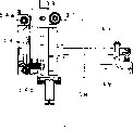
Fig. 1 is the block diagram of the medicament packaging device of this example.
Fig. 2 is the block diagram of expression powder medicine dispenser.
Fig. 3 represents the block diagram of the state behind the bench board of pulling out from Fig. 2.
State after Fig. 4 represents a part of parts of powder medicine dispenser are removed, the block diagram of seeing from the angle different with Fig. 2.
Fig. 5 is the upward view of powder medicine dispenser shown in Figure 2.
Fig. 6 is the upward view of powder medicine dispenser shown in Figure 3.
Fig. 7 is the cutaway view of powder medicine dispenser shown in Figure 2.
Fig. 8 is the block diagram of expression powder medicine dispenser.
Fig. 9 is the block diagram of the Handling device of presentation graphs 8.
Figure 10 is the cutaway view of the Handling device of Fig. 9.
Figure 11 a is the exploded perspective view that is arranged at the hopper of powder medicine packing department shown in Figure 8.
Figure 11 b is the block diagram of the state of upper side hopper from another viewpoint.
Figure 12 is the planar view of the packaging system of expression powder medicine packing department shown in Figure 8.
Figure 13 is the lateral plan of Figure 12.
Figure 14 is the block diagram of the 1st cam part that is arranged at the packaging system of Figure 12.
Figure 15 is the block diagram of the 2nd cam part that is arranged at the packaging system of Figure 12.
Figure 16 is the planar view of keeping out of the way state of expression packaging system shown in Figure 12.
Figure 17 is the lateral plan of Figure 16.
Figure 18 is the partial enlarged drawing of keeping out of the way state of expression package module shown in Figure 12.
Figure 19 is the partial enlarged drawing of the encapsulation readiness of expression package module shown in Figure 12.
Figure 20 is the partial enlarged drawing of the encapsulation state of expression package module shown in Figure 12.
The specific embodiment
Below, example of the present invention is described with reference to the accompanying drawings.
Fig. 1 illustrates the medicament packaging device of this example.This medicament packaging device has powder medicine dispenser 1 and powder medicine packing department 2.
To shown in Figure 6, powder medicine dispenser 1 is respectively equipped with the 1st disk the 5, the 2nd disk 6, powder medicine feedway 7a, 7b and transfers to device 8 (referring to Fig. 4, Fig. 7) on the bench board 4 of being located at device body 3 upper surfaces as Fig. 2.
The upper surface of device body 3 can be covered by shutter door 9 with opening, and two positions at both sides is formed with placement section 3a, 3b respectively forwardly, and placement section 3a, 3b are used to place the containers such as mortar of tablet being smash usefulness such as powdered.In addition, the upper surface both sides at device body 3 are provided with guide rail 10.On a side rails 10,, be provided with tooth bar 10a in the place ahead of device body 3 one side.
The 1st disk 5 and the 2nd disk 6 have the circular-arc circumferential groove of section 13, supply with powder medicine to this circumferential groove 13.The 1st disk 5 is arranged on than the high slightly position of the 2nd disk 6, two disks on bench board 4 with the local overlapping state setting of peripheral part.Therefore whole device can be done small compact.
The 1st disk 5, the neighboring comprise zone with the 2nd disk 6 laps at least, be formed with guide edge portion 14, the powder medicine that prevents to supply with the circumferential groove 13 of the 1st disk drops on the 2nd disk 6.In addition, but the 1st disk 5 is that the center free rotary ground supporting is being roughly on the fan-shaped intermediate plate 16 with axial region 5a, and passes through the propulsive effort of intermediary's transmission of gear 5b from the 1st driving motor 15a.Intermediate plate 16 is arranged at the through hole 11a of bench board 4, can be that the center rotates freely with rotating shaft 16a.Rotating shaft 16a passes bench board 4, is formed with the gear part 16b that local extension forms at the lower end peripheral part.When with bench board 4 when device body 3 is forwards pulled out, this gear part 16b and the tooth bar 10a engagement of being located at guide rail 10.Thus, intermediate plate 16 is that the center rotates with rotating shaft 16a, and the 1st disk 5 moves thereupon.At this moment, the 1st driving motor 15a is owing to be provided with and dodge hole 12 and can avoid colliding with bench board 4.In addition, because intermediate plate 16 and the 1st disk 5 are only supported by rotating shaft 16a, so, at the lower surface of intermediate plate 16, not shown accessory plate or bearing etc. are set suitably, can alleviate the burden of countershaft 16a.In addition, intermediate plate 16 can lock with lockout mechanisms such as screw actuator (not shown), makes that intermediate plate 16 can not rotate when not rotating powder medicine feedway 7.
The 2nd disk 6 is supported on the through hole 11b of described bench board 4 free to rotately.The 2nd disk 6 drives thereby can do rotation by the power of gear 6a transmission from the 2nd driving motor 15b.
Powder medicine feedway 7a, 7b are always known structure No. the 2669511st, Japanese patent gazette (for example referring to), and the limit makes disk 5,6 rotation limits will be supplied in the circumferential groove 13 that powder medicine in the hopper is supplied with disk 5,6 successively.Powder medicine feedway 7a is located at bench board 4, can and recess between the position of the 1st disk 5 and move in the position of the circumferential groove 13 that powder medicine can be supplied with the 1st disk 5.Certainly, the 1st disk 5 not only also can be made the 2nd disk 6 also can be moved.Thus, can further improve the cleaning performance on the bench board, more satisfactory.
Transfer to device be always known structure (for example, referring to the open 2000-85719 communique of Japanese Patent), be disposed at the core of each disk, the powder medicine that is contained in the disk circumferential groove 13 is transferred to one by one by the amount of each bag, make powder medicine drop to powder medicine packing department 2.
Powder medicine packing department 2 as shown in Figure 8, have: will be wound on the Handling device 19 that wrapper 18 on the reel 17 is transported to powder medicine packing department 2 usefulness automatically, powder medicine is supplied with the hopper parts 20 of carrying the wrapper 18 that comes, and the packaging system 21 that the wrapper 18 of supplying with powder medicine is carried out heat-seal.
As shown in figure 11, hopper parts 20 are made of funnelform upper side hopper 32 and lower side hopper 33.Upper side hopper 32 is divided into tablet path 32a and powder medicine path 32b, and the lower opening portion of powder medicine path 32b is opened and closed by opening-closing plate 34.Opening-closing plate 34 opens and closes by the transmission by the propulsive effort of electrical motor 41 described later of not shown synchronous belt and timing belt pulley.Therefore, the powder medicine of supplying with from disk 5,6 can not fall very long distance and directly arrive wrapper 18, and dispersing when falling is prevented.The substantially oblong-shaped shape of section of the lower opening tube 33a of portion of lower side hopper 33, the size of its major axis side is consistent with the Packaging Paper width, and its edge of opening portion bends to the shape of central portion depression.Constitute thus, can prevent that also powder medicine from dispersing towards periphery in wrapper 18.In addition, the powder medicine that flies upward in lower side hopper 33 is discharged by bleeder line 33b.Again, discharge swimmingly from bleeder line 33b, be formed with air entrance hole 33c across not shown (prevent powder medicine from falling usefulness) next door in order to make air.
Shown in Figure 12 and 13, packaging system 21 is on the adapter plate 36 of constituent apparatus body 3 front faces the 1st package module 37 and the 2nd package module 38 to be set with opening and closing, and corresponding surface is installed under the bevelled state to the wrapper 18 of oblique below.Adapter plate 36 is provided with the 1st and the 2nd mounted panel 39a, 39b side by side at its back side, the 3rd mounted panel 39c is fixed in two mounted panel 39a, 39b.The 2nd cam part 41 that the 1st cam part the 40, the 2nd electrical motor 41a that two package modules 37,38 are driven by the 1st electrical motor 40a drives makes the contact of encapsulation paper, separates, and the position that can intersect vertically at the broken line with the wrapper 18 of doubling and the position of opposition side roughly are the T font and encapsulate.In addition, the wrapper 18 that is supplied in packaging system 21 is by a pair of outlet roller 42a, 42b clamping, and one of them outlet roller is driven and can be carried by not shown stepper motor rotation.The carrying amount of wrapper 18 changes according to the difference of per 1 bag pharmaceutical quantities.Herein, the pulse change according to stepper motor determines the carrying amount.Thus, even if cutter (not shown) is fixed in adapter plate 36, also can keep in position wrapper 18 being cut off always.
The 1st package module 37 has the 1st heat-seal portion 43 that roughly is the T font, as Figure 12 and shown in Figure 13, is fixed in an end of the slide shaft 45 of the bearing portion 44 that connects adapter plate 36.The 1st heat-seal portion 43 built-in having heaters encapsulate wrapper 18 heating.The other end of slide shaft 45 is formed with the 45a of blade of a sword portion, is respectively arranged with the 1st bearing the 46, the 2nd bearing 47 and the 3rd bearing 48 herein.Be equipped with spring (not shown) between the bearing portion 44 of 45a of blade of a sword portion and adapter plate 36.Thus, the 1st package module 37 is located in the retreating position near adapter plate 36.In addition, the 45a of blade of a sword portion of slide shaft 45 is provided with the arm 49 that connects adapter plate 36 side extension forwards.The front end of arm 49 forms the 1st press section 50 and the 2nd press section 51 by the bearing that is arranged at two places.
The 2nd package module 38 has the 2nd heat-seal portion 52 with the 1st heat-seal portion 43 subtends configuration of aforementioned the 1st package module 37, but is installed on the lid 53 of the freely openable that covers two package modules 37,38 free to rotately.That is, on the lid 53, be that the center is provided with accessory plate 54 free to rotately with rotating shaft 54a, by spring 54b aforementioned the 2nd package module 38 is being installed under the power-assisted state of projected direction on this accessory plate 54.Again, the 2nd package module 38 is subjected to towards the application force of lid 53 1 sides by the not shown spring that is arranged between accessory plate 54 and the lid 53, with auxiliary cam 55 butts that are arranged at lid 53 free to rotately.Auxiliary cam 55 is provided with auxiliary bearing 56 at the axial region 56a of off-centre setting, and this auxiliary bearing 56 can be arranged in the slotted hole 57a of auxiliary block 57 with being free to slide.Auxiliary block 57, by pushed the bar 57b from this extension by the 1st press section 50 of aforementioned arm 49, making auxiliary cam 55 is that rotate in the scope of about 90 degree at the center with axial region 56a.Thus, the 2nd package module 38 is by accessory plate 54, orientates as parallel with lid 53 respectively or tilts near lid 53 sides.In addition, be provided with the hold assembly 58 of clamping wrapper 18 in the lid 53.Hold assembly 58 is by being that a pair of holding piece 59a, the 59b that the center is provided with constitutes with the fulcrum free to rotately.The subtend face of holding piece 59a, 59b is formed with the pressure contact portion 60 of rubber etc., rotates synchronously by pitch wheel portion 61.Among one side's the holding piece 59b, extend the portion that is pressed 62 of pushing by the 1st press section 50 of aforementioned arm 49.
As shown in figure 14, the 1st cam part 40 has the 1st guiding wall 63 that forms along outer peripheral roughly half part and the 2nd guiding wall 64 that forms abreast of the 1st guiding wall 63 therewith in 2/3 scope almost, with rotating shaft 40b is that the center is installed on the 3rd mounted panel 39c free to rotately, as shown in figure 12, be arranged at the power of the 1st electrical motor 40a of the 3rd mounted panel 39c by not shown gear transmission.Thus, if positive and negative rotating drive the 1st cam electrical motor 65, then the 1st cam part 40 rotates in the scopes of about 90 degree by driven wheel and driven gear according to the detection signal of sensor 49a, 49b.So, sliding between two guiding walls 63,64 by the 1st bearing 46 and to move, slide shaft 45 slides, and the 1st package module 37 is near the retreating position of adapter plate 36 and protrude between the encapsulation ready position of adapter plate 36 and move back and forth.
As shown in figure 15, the 2nd cam part 41 is stepped, and when off-centre was provided with center of gyration portion 66, the sidepiece of metastomium 67 was formed by the part excision and dodges recess 68.Be formed with the guiding groove 70 that slides for the 3rd bearing 48 that is arranged at aforementioned slide shaft 45 in the blade of a sword portion 69.The aforementioned center of gyration of 70 pairs of guiding grooves portion 66 forms same radius at central portion, tends to its radius of two ends along with leaving central portion and reduces gradually.The 2nd cam part 41 is that the center is arranged on the 1st mounted panel 39a and the 2nd mounted panel 39b free to rotately with the rotating shaft, is arranged at the driven gear of rotating shaft, with the incorporate driven wheel engagement of the rotating shaft of the 2nd electrical motor 41a that is arranged at the 1st mounted panel 39a.Thus, as be subjected to the 2nd electrical motor 41a driving, then the 2nd cam part 41 rotates by driven wheel and driven gear.
Below, the action of the medicament packaging device of relevant aforementioned formation describes.
At first, the wrapper 18 that is wound in the doubling on the roller 17 is supplied with to Handling device 19.Gone out by sensor in case be supplied in the wrapper 18 of Handling device 19, the 1st electrical motor 26 drives belt conveyor 24 circulations and moves.Again, the 2nd electrical motor 27 drives and makes guiding elements 25 near belt conveyor 24 and along the part of belt conveyor 24.Thus, wrapper 18 becomes crimped status between belt conveyor 24 and guiding elements 25, along with the mobile of belt conveyor 24 is handled upside down.The wrapper 18 of taking out of from Handling device 19, the state that is positioned at the below with crease is directed to packing department along being changed direction by guide plate 19a, roller 19b and the formed path that roughly is the U font of guiding wall 19c.Wrapper 18 is directed behind packing department, and the 2nd electrical motor 27 drives and makes guiding elements 25 leave belt conveyor 24.Thus, act on the load of wrapper 18 in the time of can alleviating packing, can prevent breaking of wrapper etc.
In the powder medicine packing department 2, make the 1st cam part 40 turn to position shown in Figure 12 by driving the 1st cam with electrical motor 40a, the 1st bearing 46 is slided along the 1st guiding wall 63, make it between two guiding walls 63,64, move to the zone that does not have the 2nd guiding wall 64.Thus, the 1st package module 37 by slide shaft 45 as Figure 12 and the encapsulation ready position that advances to shown in Figure 19.During this state, each holding piece 59a, 59b of hold assembly 58 is open, and the 2nd package module 38 is that rotate at retreating position at the center with accessory plate 54 with rotating shaft 54a under the elastic force effect of not shown spring.That is, be not only the carrying path that the 1st package module 37, the 2 package modules 38 also leave wrapper.Thereby, lower side hopper 33 can be placed the central part of carrying the path, wrapper 18 is expanded to its both sides.Therefore, compared, be difficult for taking place the location dislocation of wrapper 18, even if how pharmaceutical quantities also can be accommodated well with only make the occasion of the one-sided expansion of wrapper 18 in the past.
Here, driving the 2nd cam rotates the 2nd cam part 41 with electrical motor 41a.Thus,, push the 2nd bearing 47 at central portion because the radius of curvature of metastomium 67 outer peripheral faces of the 2nd cam part 41 changes, by slide shaft 45 make the 1st package module 37 with the state that advances to package position as shown in figure 20 keep fixed time (for example, 0.5 second).Along with moving of slide shaft 45, the arm 49 that is arranged at the 45a of its blade of a sword portion advances, and the portion that is pressed 62 of hold assembly 58 is pushed in the 1st press section 50.Thus, each holding piece 59 of hold assembly 58 near and the clamping wrapper.Again, auxiliary block 57 is pushed by bar 57b in the 2nd press section 51, by auxiliary bearing 56 auxiliary cam 55 is rotated.Thus, auxiliary cam 55 is pushed accessory plate 54, and accessory plate 54 turns to package position shown in Figure 20 with the 2nd package module 38.Its result, be positioned at the oblique below sidepiece of lower side hopper 33 of the wrapper 18 of doubling, wrapper 18 roughly is the T font by heat-seal portion 43,52 clampings of package module 37,38, that is, in abutting connection with the zone between 2 bags and surpass half regional packed of both sides of the edge portion slightly.On the other hand, the sidepiece of oblique upper that is positioned at lower side hopper 33 by hold assembly 58 along 33 clampings of lower side hopper.Thus, guarantee to supply with the powder medicine supply area of 1 bag deal powder medicine by lower side hopper 33.
At this state, wrap the powder medicines of deals by dial-out device 8 from the 1st disk 5 or the 6 each supplies 1 of the 2nd disk according to prescription data.The powder medicine of supplying with temporarily is contained in the powder medicine path 32b by the upper side hopper 32 of opening-closing plate 34 lockings, after preventing that powder medicine from dispersing, by open opening-closing plate 34, is supplied in the powder medicine supply area of the wrapper 18 that forms as previously mentioned.In the powder medicine supply area, as previously mentioned, a side's of lower side hopper 33 sidepiece is packed, and the opposing party's sidepiece is by hold assembly 58 clampings.Thereby the state of affairs that the powder medicine of supply disperses towards periphery is prevented.
Supply finishes to the powder medicine supply area whenever powder medicine, then drives the 2nd electrical motor 41a, makes the 2nd cam part 41 rotate weeks, and rotation simultaneously drives outlet roller 42a, 42b carrying 1 and wraps the wrapper 18 of deal.Thus, as shown in figure 19, when the 1st package module 37 and the 2nd package module 38 left wrapper 18 together, wrapper 18 was handled upside down under the state of being removed by the state of hold assembly 58 clampings.After, proceed the packing of powder medicine according to prescription data with aforementioned same action.
Do not pack the occasion of processing,, drive with electrical motor 40a, make the 1st cam part 40 to rotated position shown in Figure 16 by the 1st cam at packing department.As Figure 16 and shown in Figure 17, the 1st bearing 46 moves along the 2nd guiding wall 64, and the 1st package module 37 moves to retreating position by slide shaft 45.Therefore, the 1st package module 37 is not packed the occasion of processing away from wrapper 18, can get rid of 43 pairs of wrappers 18 of hi-heat the 1st heat-seal portion and medicament and bring bad influence.
In addition, the occasion of necessary cleaning disk etc., if open shutter door 9, rotation powder medicine feedway 7a, 7b, then the locking-in state of intermediate plate 16 is disengaged.By supply with the powder medicine feedway 7a of powder medicine, the rotation of 7b on the 1st disk 5, the cleaning in the easiest zone of dispersing of powder medicine becomes easy.Bench board 4 to pulling out near party of one's own, then as Fig. 3 and shown in Figure 6, is arranged at the gear part 16b and the tooth bar 10a engagement that is arranged at guide rail 10 of the 1st disk 5 rotating shafts, with the action interlock intermediate plate 16 of pulling out of bench board 4 be the center rotation with the rotating shaft.Follow in this, the 2nd disk 6 on the intermediate plate 16 is the center rotation with the rotating shaft, obtain removing with the overlap condition of the 2nd disk 6, thereby the 1st disk 5 moves to the position of easy cleaning.Because the 2nd disk 6 also is positioned at the place ahead along with pulling out bench board 4, be disengaged and the cleaning easily that becomes with the overlap condition of the 1st disk 5 again.
As can be known as described above, by the present invention, because disk is equipped on the telescopic bench board of relative device body, so, can clean the powder medicine that residues in the disk circumferential groove easily and positively although constitute simply.
Symbol description
1 powder medicine dispenser
2 powder medicine packing departments
3 device bodies
4 workbench
5 the 1st disks
6 the 2nd disks
7a, 7b powder medicine feedway
8 transfer to device
9 shutter door
10 guide rails
12 dodge the hole
13 circumferential groove
14 leading edge edges
15 the 1st drive motors
16 intermediate plates
17 rollers
18 wrapping papers
19 Handling devices
20 hopper parts
21 packaging systems
22 holding plates
23 carrying rollers
24 belt conveyor
25 guiding elements
26 the 1st electrical motors
27 the 2nd electrical motors
30 tooth bars
31 printing devices
32 upper side hoppers
33 lower side hoppers
37 the 1st package modules
38 the 2nd package modules
40 the 1st cam parts
41 the 2nd cam parts
45 slide shafts
52 the 2nd heat-seal portions
Claims (7)
1. medicament packaging device comprises:
Device body,
Be located at rotatable driving in the described device body and the disk of circumferential groove arranged,
Be configured in locational powder medicine feedway from powder medicine to the circumferential groove of described disk that to supply with in working order, the dial-out device of the powder medicine of described circumferential groove by the deal dial-out of each bag will be supplied with, and the powder medicine one that quilt is transferred to carries out wrapping packing device with wrapping successively, it is characterized in that
Described medicament packaging device also comprises the telescopic bench board of described relatively device body, and described disk is configured on the bench board.
2. medicament packaging device according to claim 1 is characterized in that, described disk is arranged to and can be moved relative to described bench board.
3. medicament packaging device according to claim 2 is characterized in that, the action of pulling out of described disk and described bench board is moved in linkage.
4. medicament packaging device as claimed in claim 1 is characterized in that,
Described powder medicine feedway is arranged to and can be able to is being supplied with between position and the retreating position that leaves described disk mobile to the powder medicine that the circumferential groove of described disk is supplied with powder medicine.
5. medicament packaging device according to claim 4 is characterized in that, also supplies with the position at described powder medicine and is provided with the lockout mechanism that described disk can not be rotated.
6. medicament packaging device according to claim 5 is characterized in that, the peripheral part of the disk above being positioned among the described disk is formed with and prevents to be contained in the guide portion that the powder medicine in the described circumferential groove falls.
7. medicament packaging device comprises:
Device body,
Be located at rotatable driving in the described device body and the disk of circumferential groove arranged,
Be configured in locational powder medicine feedway from powder medicine to the circumferential groove of described disk that can supply with in working order,
To supply with the dial-out device of the powder medicine of described circumferential groove by the deal dial-out of each bag,, and to the packing device that the powder medicine of being transferred to is packed with wrapping successively, it is characterized in that,
Be provided with described disk with local up and down overlapping state at Liang Chu, and be provided with the disk travel mechanism that described disk is moved and described lap is disappeared.
Applications Claiming Priority (2)
| Application Number | Priority Date | Filing Date | Title |
|---|---|---|---|
| JP2002130692A JP3964730B2 (en) | 2002-05-02 | 2002-05-02 | Drug packaging device |
| JP2002130692 | 2002-05-02 |
Related Child Applications (3)
| Application Number | Title | Priority Date | Filing Date |
|---|---|---|---|
| CNB2006100990721A Division CN100465069C (en) | 2002-05-02 | 2003-04-30 | Medicine packaging apparatus |
| CNB200510076059XA Division CN100422051C (en) | 2002-05-02 | 2003-04-30 | Medicine packaging apparatus |
| CNB2005100760585A Division CN100427362C (en) | 2002-05-02 | 2003-04-30 | Medicine packaging apparatus |
Publications (2)
| Publication Number | Publication Date |
|---|---|
| CN1454821A CN1454821A (en) | 2003-11-12 |
| CN1330534C true CN1330534C (en) | 2007-08-08 |
Family
ID=29267722
Family Applications (4)
| Application Number | Title | Priority Date | Filing Date |
|---|---|---|---|
| CNB2006100990721A Expired - Fee Related CN100465069C (en) | 2002-05-02 | 2003-04-30 | Medicine packaging apparatus |
| CNB031243169A Expired - Fee Related CN1330534C (en) | 2002-05-02 | 2003-04-30 | Medicine packaging device |
| CNB200510076059XA Expired - Fee Related CN100422051C (en) | 2002-05-02 | 2003-04-30 | Medicine packaging apparatus |
| CNB2005100760585A Expired - Fee Related CN100427362C (en) | 2002-05-02 | 2003-04-30 | Medicine packaging apparatus |
Family Applications Before (1)
| Application Number | Title | Priority Date | Filing Date |
|---|---|---|---|
| CNB2006100990721A Expired - Fee Related CN100465069C (en) | 2002-05-02 | 2003-04-30 | Medicine packaging apparatus |
Family Applications After (2)
| Application Number | Title | Priority Date | Filing Date |
|---|---|---|---|
| CNB200510076059XA Expired - Fee Related CN100422051C (en) | 2002-05-02 | 2003-04-30 | Medicine packaging apparatus |
| CNB2005100760585A Expired - Fee Related CN100427362C (en) | 2002-05-02 | 2003-04-30 | Medicine packaging apparatus |
Country Status (4)
| Country | Link |
|---|---|
| JP (1) | JP3964730B2 (en) |
| KR (7) | KR100969897B1 (en) |
| CN (4) | CN100465069C (en) |
| TW (3) | TWI285617B (en) |
Families Citing this family (10)
| Publication number | Priority date | Publication date | Assignee | Title |
|---|---|---|---|---|
| JP4713125B2 (en) * | 2004-10-14 | 2011-06-29 | 株式会社湯山製作所 | Drug packaging device |
| JP5133777B2 (en) * | 2008-05-23 | 2013-01-30 | 株式会社イシダ | Packaging machine |
| KR101529702B1 (en) * | 2008-10-09 | 2015-06-17 | 가부시키가이샤 유야마 세이사쿠쇼 | Medicine packing unit and packing control method thereof |
| TWI411430B (en) * | 2009-11-26 | 2013-10-11 | Jung Hua Shao | Automatic injection of drugs and packaging methods |
| KR101104849B1 (en) * | 2011-01-05 | 2012-01-16 | 안종범 | Dispaly unit carrying deivce |
| JP6287844B2 (en) * | 2012-10-03 | 2018-03-07 | 株式会社湯山製作所 | Drug inspection system |
| WO2014098493A1 (en) * | 2012-12-20 | 2014-06-26 | Kim Tae You | Medicine preparation method and medicine preparation apparaus |
| KR102401482B1 (en) | 2013-11-22 | 2022-05-24 | 가부시키가이샤 유야마 세이사쿠쇼 | Medicine dispensing device |
| CN105173206B (en) * | 2015-10-15 | 2018-12-14 | 刘思佳 | Medicine-packaging machine |
| CN107757984B (en) * | 2016-08-17 | 2020-04-17 | 诸暨市银生珍珠养殖有限公司 | Quantitative feeding device for pearl packaging assembly line |
Citations (1)
| Publication number | Priority date | Publication date | Assignee | Title |
|---|---|---|---|---|
| JP2669511B2 (en) * | 1990-12-21 | 1997-10-29 | 園部 尚俊 | Drug packaging device |
Family Cites Families (26)
| Publication number | Priority date | Publication date | Assignee | Title |
|---|---|---|---|---|
| JPH0688561B2 (en) * | 1989-08-08 | 1994-11-09 | 園部 尚俊 | Granule packing machine |
| JP2807931B2 (en) * | 1991-04-18 | 1998-10-08 | 株式会社 東京商会 | Drug packaging machine |
| CN1078209A (en) * | 1992-04-28 | 1993-11-10 | 周显权 | Micro-computer controlled traditional Chinese medicine pill wrapping machine |
| KR940009267A (en) * | 1992-10-15 | 1994-05-20 | 전성원 | Double layer high rigidity vibration damping sheet for automobile |
| CN2143593Y (en) * | 1992-10-17 | 1993-10-13 | 高景海 | Thermal closing soft packing machine for tablet |
| JPH0769330A (en) * | 1993-09-01 | 1995-03-14 | Hidetoshi Hirae | Rolling and wrapping apparatus for hand towel |
| CN2203266Y (en) * | 1994-03-29 | 1995-07-12 | 锦州东方包装机械制造公司 | Aluminium-plastic bubble packing machine with miniature suction bubble and heat-sealing combined mould roller |
| KR960000188A (en) * | 1994-06-10 | 1996-01-25 | 김준호 | Heating device of packing machine |
| JP3476935B2 (en) * | 1994-12-14 | 2003-12-10 | 株式会社湯山製作所 | Drug volume dividing method and dividing device |
| CN2251528Y (en) * | 1996-03-05 | 1997-04-09 | 饶智益 | Wrapping material feeding device for packing machine |
| JP3186970B2 (en) * | 1996-03-19 | 2001-07-11 | 株式会社湯山製作所 | Powder powder split control device |
| CA2316140C (en) * | 1996-09-20 | 2003-12-30 | Itsuo Yasunaga | Core pipe based magnetic sensing system for adjusting tension in rolls of winding sheet material |
| JP3720491B2 (en) * | 1996-11-05 | 2005-11-30 | 高園産業株式会社 | Drug packaging device |
| CN2311437Y (en) * | 1996-11-11 | 1999-03-24 | 顾正容 | Multi-function tablet sheet automatic packing machine |
| JP3039777B2 (en) * | 1997-04-18 | 2000-05-08 | 日本精機株式会社 | Stretch wrapping machine |
| JP2000085701A (en) * | 1998-09-11 | 2000-03-28 | Yuyama Seisakusho:Kk | Powdered medicine feeder |
| JP4302818B2 (en) * | 1999-05-26 | 2009-07-29 | 株式会社湯山製作所 | Drug packaging device |
| JP2000344203A (en) * | 1999-06-04 | 2000-12-12 | Ueda Avancer Corp | Dispensing machine |
| JP2001031003A (en) * | 1999-07-21 | 2001-02-06 | Takazono Sangyo Kk | Medicine packaging apparatus |
| KR200169923Y1 (en) | 1999-09-16 | 2000-02-15 | 주식회사협신메디칼 | Tension unit for automatic tablet sorting and counting machine |
| JP2001129059A (en) * | 1999-11-09 | 2001-05-15 | Sanyo Electric Co Ltd | Solid preparation filling apparatus |
| JP2001199414A (en) | 2000-01-18 | 2001-07-24 | Sanko Kikai Kk | Longitudinal sealing apparatus for automatic packaging machine |
| JP2002019737A (en) * | 2000-07-04 | 2002-01-23 | Takazono Sangyo Kk | Heat-sealing device |
| JP4404454B2 (en) * | 2000-07-05 | 2010-01-27 | 高園産業株式会社 | Heat sealing device and medicine packaging device |
| JP2002019713A (en) | 2000-07-06 | 2002-01-23 | Takazono Sangyo Kk | Heat sealer and medicine subdivision packing apparatus |
| KR20010069923A (en) * | 2001-05-18 | 2001-07-25 | 김성윤 | Logistics by use of mobile letter service |
-
2002
- 2002-05-02 JP JP2002130692A patent/JP3964730B2/en not_active Expired - Fee Related
-
2003
- 2003-04-30 CN CNB2006100990721A patent/CN100465069C/en not_active Expired - Fee Related
- 2003-04-30 CN CNB031243169A patent/CN1330534C/en not_active Expired - Fee Related
- 2003-04-30 CN CNB200510076059XA patent/CN100422051C/en not_active Expired - Fee Related
- 2003-04-30 CN CNB2005100760585A patent/CN100427362C/en not_active Expired - Fee Related
- 2003-05-01 KR KR1020030027943A patent/KR100969897B1/en active IP Right Grant
- 2003-05-01 TW TW092112033A patent/TWI285617B/en not_active IP Right Cessation
- 2003-05-01 TW TW094113875A patent/TWI285616B/en not_active IP Right Cessation
- 2003-05-01 TW TW094113874A patent/TWI285619B/en not_active IP Right Cessation
- 2003-12-05 KR KR1020030087848A patent/KR20040016434A/en not_active Application Discontinuation
- 2003-12-05 KR KR1020030087849A patent/KR20040016435A/en not_active Application Discontinuation
-
2009
- 2009-12-08 KR KR1020090120997A patent/KR100987308B1/en active IP Right Grant
- 2009-12-08 KR KR1020090120995A patent/KR100996509B1/en active IP Right Grant
- 2009-12-08 KR KR1020090120998A patent/KR100987309B1/en active IP Right Grant
- 2009-12-08 KR KR1020090120994A patent/KR100987307B1/en active IP Right Grant
Patent Citations (1)
| Publication number | Priority date | Publication date | Assignee | Title |
|---|---|---|---|---|
| JP2669511B2 (en) * | 1990-12-21 | 1997-10-29 | 園部 尚俊 | Drug packaging device |
Also Published As
| Publication number | Publication date |
|---|---|
| KR20100004084A (en) | 2010-01-12 |
| CN1693145A (en) | 2005-11-09 |
| KR100987307B1 (en) | 2010-10-12 |
| CN1891575A (en) | 2007-01-10 |
| TWI285616B (en) | 2007-08-21 |
| TW200306934A (en) | 2003-12-01 |
| KR100996509B1 (en) | 2010-11-24 |
| JP3964730B2 (en) | 2007-08-22 |
| KR20100004083A (en) | 2010-01-12 |
| JP2003327202A (en) | 2003-11-19 |
| KR100987308B1 (en) | 2010-10-12 |
| CN1696016A (en) | 2005-11-16 |
| KR20040016434A (en) | 2004-02-21 |
| CN1454821A (en) | 2003-11-12 |
| KR100987309B1 (en) | 2010-10-12 |
| KR20030086420A (en) | 2003-11-10 |
| CN100427362C (en) | 2008-10-22 |
| TWI285619B (en) | 2007-08-21 |
| CN100465069C (en) | 2009-03-04 |
| KR100969897B1 (en) | 2010-07-13 |
| KR20100004086A (en) | 2010-01-12 |
| KR20040016435A (en) | 2004-02-21 |
| CN100422051C (en) | 2008-10-01 |
| TW200528351A (en) | 2005-09-01 |
| TWI285617B (en) | 2007-08-21 |
| TW200530082A (en) | 2005-09-16 |
| KR20100004085A (en) | 2010-01-12 |
Similar Documents
| Publication | Publication Date | Title |
|---|---|---|
| KR100405292B1 (en) | Solid agent packing device | |
| CN1330534C (en) | Medicine packaging device | |
| US6766920B2 (en) | Medicine feed unit | |
| JPH10118159A (en) | Solid preparation packaging device | |
| JP4330886B2 (en) | Drug distribution device and drug packaging device | |
| JP4700631B2 (en) | Drug packaging device | |
| JP3604842B2 (en) | Solid preparation filling device | |
| JP4301922B2 (en) | Drug packaging device | |
| JP4477153B2 (en) | Drug packaging device | |
| JP4354707B2 (en) | Drug distribution device and drug packaging device | |
| JP4436791B2 (en) | Drug packaging device | |
| JP4371778B2 (en) | Drug packaging device | |
| JPH0956783A (en) | Solid preparation packing unit | |
| JP2009173348A (en) | Medicine packaging apparatus |
Legal Events
| Date | Code | Title | Description |
|---|---|---|---|
| C06 | Publication | ||
| PB01 | Publication | ||
| C10 | Entry into substantive examination | ||
| SE01 | Entry into force of request for substantive examination | ||
| C14 | Grant of patent or utility model | ||
| GR01 | Patent grant | ||
| C17 | Cessation of patent right | ||
| CF01 | Termination of patent right due to non-payment of annual fee |
Granted publication date: 20070808 Termination date: 20120430 |