CN1310223C - Mastering device, disc manufacturing method, disc-shaped recording medium, disc reproduction device, and disc reproduction method - Google Patents
Mastering device, disc manufacturing method, disc-shaped recording medium, disc reproduction device, and disc reproduction method Download PDFInfo
- Publication number
- CN1310223C CN1310223C CNB2003801003115A CN200380100311A CN1310223C CN 1310223 C CN1310223 C CN 1310223C CN B2003801003115 A CNB2003801003115 A CN B2003801003115A CN 200380100311 A CN200380100311 A CN 200380100311A CN 1310223 C CN1310223 C CN 1310223C
- Authority
- CN
- China
- Prior art keywords
- signal
- information
- numerical information
- read
- disc
- Prior art date
- Legal status (The legal status is an assumption and is not a legal conclusion. Google has not performed a legal analysis and makes no representation as to the accuracy of the status listed.)
- Expired - Fee Related
Links
- 238000000034 method Methods 0.000 title claims description 47
- 238000004519 manufacturing process Methods 0.000 title claims description 16
- 230000010354 integration Effects 0.000 claims description 31
- 230000005855 radiation Effects 0.000 claims description 6
- 230000007274 generation of a signal involved in cell-cell signaling Effects 0.000 claims description 3
- 230000007547 defect Effects 0.000 abstract 1
- 230000001360 synchronised effect Effects 0.000 description 36
- 238000006243 chemical reaction Methods 0.000 description 26
- 230000003287 optical effect Effects 0.000 description 23
- 230000008569 process Effects 0.000 description 21
- 238000006073 displacement reaction Methods 0.000 description 20
- 238000001514 detection method Methods 0.000 description 17
- 230000002950 deficient Effects 0.000 description 11
- BCJNRNBOQWJRIM-QFIPXVFZSA-N (2s)-3-(4-cyanonaphthalen-1-yl)oxy-n-[4-cyano-3-(trifluoromethyl)phenyl]-2-hydroxy-2-methylpropanamide Chemical compound O=C([C@@](O)(COC=1C2=CC=CC=C2C(C#N)=CC=1)C)NC1=CC=C(C#N)C(C(F)(F)F)=C1 BCJNRNBOQWJRIM-QFIPXVFZSA-N 0.000 description 9
- 238000003825 pressing Methods 0.000 description 6
- 238000010586 diagram Methods 0.000 description 5
- 239000000758 substrate Substances 0.000 description 5
- 239000000700 radioactive tracer Substances 0.000 description 4
- 239000011347 resin Substances 0.000 description 4
- 229920005989 resin Polymers 0.000 description 4
- 238000013459 approach Methods 0.000 description 3
- 230000015572 biosynthetic process Effects 0.000 description 3
- 230000008859 change Effects 0.000 description 3
- 239000011248 coating agent Substances 0.000 description 3
- 238000000576 coating method Methods 0.000 description 3
- 238000012937 correction Methods 0.000 description 3
- 230000002441 reversible effect Effects 0.000 description 3
- 238000003860 storage Methods 0.000 description 3
- 238000012360 testing method Methods 0.000 description 3
- 230000007704 transition Effects 0.000 description 3
- 238000013478 data encryption standard Methods 0.000 description 2
- 238000005516 engineering process Methods 0.000 description 2
- 230000006870 function Effects 0.000 description 2
- 239000011159 matrix material Substances 0.000 description 2
- 239000002184 metal Substances 0.000 description 2
- 230000005236 sound signal Effects 0.000 description 2
- 238000010023 transfer printing Methods 0.000 description 2
- 238000012795 verification Methods 0.000 description 2
- 244000287680 Garcinia dulcis Species 0.000 description 1
- 238000010276 construction Methods 0.000 description 1
- 125000004122 cyclic group Chemical group 0.000 description 1
- 238000005323 electroforming Methods 0.000 description 1
- 230000008030 elimination Effects 0.000 description 1
- 238000003379 elimination reaction Methods 0.000 description 1
- 239000011521 glass Substances 0.000 description 1
- 230000006872 improvement Effects 0.000 description 1
- 238000002347 injection Methods 0.000 description 1
- 239000007924 injection Substances 0.000 description 1
- 230000007246 mechanism Effects 0.000 description 1
- 230000005055 memory storage Effects 0.000 description 1
- 230000002085 persistent effect Effects 0.000 description 1
- 229920002120 photoresistant polymer Polymers 0.000 description 1
- 238000005498 polishing Methods 0.000 description 1
- 230000003362 replicative effect Effects 0.000 description 1
- 230000004044 response Effects 0.000 description 1
- 230000000717 retained effect Effects 0.000 description 1
- 230000011218 segmentation Effects 0.000 description 1
Images


Classifications
-
- G—PHYSICS
- G11—INFORMATION STORAGE
- G11B—INFORMATION STORAGE BASED ON RELATIVE MOVEMENT BETWEEN RECORD CARRIER AND TRANSDUCER
- G11B7/00—Recording or reproducing by optical means, e.g. recording using a thermal beam of optical radiation by modifying optical properties or the physical structure, reproducing using an optical beam at lower power by sensing optical properties; Record carriers therefor
- G11B7/24—Record carriers characterised by shape, structure or physical properties, or by the selection of the material
- G11B7/26—Apparatus or processes specially adapted for the manufacture of record carriers
-
- G—PHYSICS
- G11—INFORMATION STORAGE
- G11B—INFORMATION STORAGE BASED ON RELATIVE MOVEMENT BETWEEN RECORD CARRIER AND TRANSDUCER
- G11B20/00—Signal processing not specific to the method of recording or reproducing; Circuits therefor
- G11B20/00086—Circuits for prevention of unauthorised reproduction or copying, e.g. piracy
- G11B20/00572—Circuits for prevention of unauthorised reproduction or copying, e.g. piracy involving measures which change the format of the recording medium
- G11B20/00586—Circuits for prevention of unauthorised reproduction or copying, e.g. piracy involving measures which change the format of the recording medium said format change concerning the physical format of the recording medium
- G11B20/00601—Circuits for prevention of unauthorised reproduction or copying, e.g. piracy involving measures which change the format of the recording medium said format change concerning the physical format of the recording medium wherein properties of tracks are altered, e.g., by changing the wobble pattern or the track pitch, or by adding interruptions or eccentricity
-
- G—PHYSICS
- G11—INFORMATION STORAGE
- G11B—INFORMATION STORAGE BASED ON RELATIVE MOVEMENT BETWEEN RECORD CARRIER AND TRANSDUCER
- G11B20/00—Signal processing not specific to the method of recording or reproducing; Circuits therefor
- G11B20/10—Digital recording or reproducing
-
- G—PHYSICS
- G11—INFORMATION STORAGE
- G11B—INFORMATION STORAGE BASED ON RELATIVE MOVEMENT BETWEEN RECORD CARRIER AND TRANSDUCER
- G11B7/00—Recording or reproducing by optical means, e.g. recording using a thermal beam of optical radiation by modifying optical properties or the physical structure, reproducing using an optical beam at lower power by sensing optical properties; Record carriers therefor
- G11B7/004—Recording, reproducing or erasing methods; Read, write or erase circuits therefor
- G11B7/005—Reproducing
- G11B7/0053—Reproducing non-user data, e.g. wobbled address, prepits, BCA
-
- G—PHYSICS
- G11—INFORMATION STORAGE
- G11B—INFORMATION STORAGE BASED ON RELATIVE MOVEMENT BETWEEN RECORD CARRIER AND TRANSDUCER
- G11B7/00—Recording or reproducing by optical means, e.g. recording using a thermal beam of optical radiation by modifying optical properties or the physical structure, reproducing using an optical beam at lower power by sensing optical properties; Record carriers therefor
- G11B7/007—Arrangement of the information on the record carrier, e.g. form of tracks, actual track shape, e.g. wobbled, or cross-section, e.g. v-shaped; Sequential information structures, e.g. sectoring or header formats within a track
- G11B7/00736—Auxiliary data, e.g. lead-in, lead-out, Power Calibration Area [PCA], Burst Cutting Area [BCA], control information
-
- G—PHYSICS
- G11—INFORMATION STORAGE
- G11B—INFORMATION STORAGE BASED ON RELATIVE MOVEMENT BETWEEN RECORD CARRIER AND TRANSDUCER
- G11B7/00—Recording or reproducing by optical means, e.g. recording using a thermal beam of optical radiation by modifying optical properties or the physical structure, reproducing using an optical beam at lower power by sensing optical properties; Record carriers therefor
- G11B7/24—Record carriers characterised by shape, structure or physical properties, or by the selection of the material
- G11B7/2407—Tracks or pits; Shape, structure or physical properties thereof
- G11B7/24085—Pits
- G11B7/24088—Pits for storing more than two values, i.e. multi-valued recording for data or prepits
-
- G—PHYSICS
- G11—INFORMATION STORAGE
- G11B—INFORMATION STORAGE BASED ON RELATIVE MOVEMENT BETWEEN RECORD CARRIER AND TRANSDUCER
- G11B7/00—Recording or reproducing by optical means, e.g. recording using a thermal beam of optical radiation by modifying optical properties or the physical structure, reproducing using an optical beam at lower power by sensing optical properties; Record carriers therefor
- G11B7/24—Record carriers characterised by shape, structure or physical properties, or by the selection of the material
- G11B7/26—Apparatus or processes specially adapted for the manufacture of record carriers
- G11B7/261—Preparing a master, e.g. exposing photoresist, electroforming
-
- G—PHYSICS
- G11—INFORMATION STORAGE
- G11B—INFORMATION STORAGE BASED ON RELATIVE MOVEMENT BETWEEN RECORD CARRIER AND TRANSDUCER
- G11B20/00—Signal processing not specific to the method of recording or reproducing; Circuits therefor
- G11B20/00086—Circuits for prevention of unauthorised reproduction or copying, e.g. piracy
- G11B20/0021—Circuits for prevention of unauthorised reproduction or copying, e.g. piracy involving encryption or decryption of contents recorded on or reproduced from a record carrier
- G11B20/00217—Circuits for prevention of unauthorised reproduction or copying, e.g. piracy involving encryption or decryption of contents recorded on or reproduced from a record carrier the cryptographic key used for encryption and/or decryption of contents recorded on or reproduced from the record carrier being read from a specific source
- G11B20/00253—Circuits for prevention of unauthorised reproduction or copying, e.g. piracy involving encryption or decryption of contents recorded on or reproduced from a record carrier the cryptographic key used for encryption and/or decryption of contents recorded on or reproduced from the record carrier being read from a specific source wherein the key is stored on the record carrier
- G11B20/00405—Circuits for prevention of unauthorised reproduction or copying, e.g. piracy involving encryption or decryption of contents recorded on or reproduced from a record carrier the cryptographic key used for encryption and/or decryption of contents recorded on or reproduced from the record carrier being read from a specific source wherein the key is stored on the record carrier the key being stored by varying characteristics of the recording track, e.g. by altering the track pitch or by modulating the wobble track
-
- G—PHYSICS
- G11—INFORMATION STORAGE
- G11B—INFORMATION STORAGE BASED ON RELATIVE MOVEMENT BETWEEN RECORD CARRIER AND TRANSDUCER
- G11B23/00—Record carriers not specific to the method of recording or reproducing; Accessories, e.g. containers, specially adapted for co-operation with the recording or reproducing apparatus ; Intermediate mediums; Apparatus or processes specially adapted for their manufacture
- G11B23/28—Indicating or preventing prior or unauthorised use, e.g. cassettes with sealing or locking means, write-protect devices for discs
Abstract
Second digital information serving as copyright protection information can be stably and reliably read without any effect of a defect or pit missing on a disk-shaped recording medium. The second digital information is recorded onto a disk-shaped recording medium by wobbling a pit sequence recorded as a first signal. The second digital information is recorded so that a plurality of bits constituting the second digital information are allocated in a unit period of an identical sync signal contained in the first signal. During playback, the plurality of bits constituting the recorded second digital information are read a plurality of times every unit period of the sync signal, and information of the read bits is then integrated. Thus, information from a large number of wobbled pits across unit periods of a plurality of sync signals can be integrated to determine the bit values.
Description
Technical field
The present invention relates to a kind of making disc recording medium and make the disc manufacturing method of manufacturing disc recording medium such as CD or DVD such as the former dish making apparatus of CD (compact disk) or the former dish of DVD (digital universal disc) with by this former dish.The invention further relates to the device for playing disk of disc recording medium such as CD or DVD and broadcast disc recording medium.
Background technology
In typical compact disk (CD), the area code that is called IFPI (phonograph industry League of Nations) code be recorded in than the employed signal of recording user such as the zone of sound signal and TOC (contents table) more in the zone at center.For preventing the illegal copies purpose of (being called piracy), this code has marks such as dealer, manufacturing works, dish sequence number.
The mark of the dealer that is write down, manufacturing works, dish sequence number etc. is visually discerned.In play CD etc., on playback equipment, can not read this mark.
That is, the content of this IFPI code can not be reflected in the operation control of playback equipment.
In addition, as indicated above, owing to content can visually be confirmed, so the problem that the IFPI code exists is that code itself is easy to be copied.
The user can easily copy to CD, DVD etc. recordable CD on it and also can arrive on the market and buy.For example, the CD-R dish that can buy of market and the equipment numerical information that allows to be recorded among the CD accurately copies by shirtsleeve operation.This copy may be violated the copyright that is subjected to Copyright Law protection, and therefore another problem that produces is that the copyright owner can not obtain repayment liberally.
In order to overcome aforesaid problem, in correlation technique, suppose that the employed information of user sets as the first information such as sound signal, then as second information stack of the information of copyright protection etc. and be recorded on the first information.
In correlation technique, for example, so a kind of CD has been proposed, wherein a plurality of specific pit train are that unit be set at information track on certain interval with the data block of tracer signal in interrupted mode, and each pit train is constructed such that center line that the part of a plurality of information pits is arranged to make it is at the radial direction top offset.
Another example has been proposed, promptly be equipped with the CD that illegal copies prevent function, in this CD in the part of specific radial zone of dish the information pits sequence on track length track in the radial direction from the center line displacement of information pits sequence, detectable signal changes (for example referring to Japanese unexamined patent publication No.9-81938) has taken place in the tracking error signal band here.
In addition, in correlation technique, a kind of optical record carrier has been proposed, wherein write down with the first information of the information of deciding with the second relevant information of control information of the broadcast of the first information, the 3rd information that wherein is different from first and second information write down with the second associating information ground so that based on second information broadcast first information time the 3rd information directly be not included in the first information of decoding (referring to Japanese unexamined patent publication No.11-66739).
In addition, in correlation technique, a kind of data medium has been proposed, wherein first data are write down to the integral multiple corresponding to duration of the basic cycle of being scheduled in pit by repeating persistent signal and convex region, wherein write down second data and this displacement in the scope of predetermined amount, as long as (referring to Japanese unexamined patent publication No.2000-242929) do not take place the offset track situation by being shifted at the center that makes pit from track on the direction perpendicular to orbital direction.
In addition, in correlation technique, a kind of optical record medium has been proposed, wherein track record is formed by continuous pit or groove, pit is formed on the track record based on master data, write down master data thus, wherein be formed within a predetermined distance spaced apartly track record on pit based on the additional data amount (referring to Japanese unexamined patent publication No.2002-197671) predetermined with the direction superior displacement of the center line quadrature of track record on orbital direction.
According to the publication in the above-mentioned correlation technique, the pit by transversal displacement (swing) writes down second information.Only optical radiation just can carried out the information record by swing to the former dish making apparatus of original disc.Therefore can not record readable device such as on the CD-R by the information of recorded in wobbles.The information of swing is recorded on the former dish, and the existence of checking this information in the process of playing.Therefore, but can eliminate and copy illegal disc such as CD-R by recording unit.
Yet the problem that exists in the publication of correlation technique is that the q.s of requirement swing detects by swinging determined information guaranteeing.This is because the signal of wobble detection has relatively poor signal noise ratio (SNR).
For example, in the Japanese unexamined patent publication No.2002-197671 of correlation technique, oscillating quantity to 100 nanometers, needs to make the dish of the swing with relatively large amount from 20 nanometers.This bigger displacement may cause may observe such as using electron microscope and confirm swing.Therefore, the problem of generation is that the content of swing can be analyzed, the danger increase of illegal copies.
Usually, a kind of programmable technology that overcomes lower SNR is to extend the zone (being pit train) of swing and use low-pass filter to eliminate noise.Yet actual optical disc playing device is designed to be used in tracking servo and adjusts the position of light beam to the center of swing.If has extended in the zone of swing, then the amplitude of swing detection signal reduces gradually according to the motion of bundle point, and the swing detection signal does not have amplitude substantially on the position that the motion of light beam is finished.
Consider this function of tracking servo, it is still not enough only to extend wobble area.This is because require bigger wobble amplitude in correlation technique.
The inventor has proposed a kind of improvement, promptly, make the pit displacement and write down according to pit along the length of track and spacing and subdata Maurer Data Record CD thereon on interior and outer radial direction with respect to the center of track, wherein the result calculated according to subdata and predetermined binary sequence makes pit displacement (referring to Japanese unexamined patent publication No.2000-195049)
In this CD, use predetermined binary sequence to detect by integrated detected by the information of recorded in wobbles.In the present invention, a position with copyright protection information is assigned in the frame of the CD that will write down.One frame is the length that equals 12 millimeters dish.This macrocyclic play signal is by integrated detected, and therefore the swing with less relatively amplitude record can be detected fully.
Therefore this publication scheme of correlation technique has greatly reduced the pit wobble amount.When overcoming defective as described above, can realize practicable copyright protection thus by correlation technique.
For example, if defective has taken place when the beginning of frame in the playing process of CD, then clock variation phenomenon (sliding in the position) may take place.
In Japanese patent application publication No. 2000-195049, if sliding, the position taken place, and as indicated above, clock becomes out-phase, and the binary sequence that uses in record is not reproduced, and therefore correct data decode is impossible.Slide unless play next synchronous mode otherwise can not overcome the position.Therefore, if when the beginning of frame defective has taken place and the position has taken place to slide, position that then can not played data, this is cumbersome.
To not have error correction code to be increased under the situation in the sub-information (being copyright protection information), if the read error of a position has taken place, then the serious problems of Fa Shenging are the played data that must start anew.
Summary of the invention
For overcoming problem mentioned above, an object of the present invention is to reduce fully to prevent the desired wobble modulations amount of copyright protection information of illegal copies CD, DVD etc. and guarantee to read this information by recorded in wobbles.
Therefore, in the present invention, former dish making apparatus writes down pit train by laser beam radiation to the former dish and writes down first numerical information and further write down second numerical information by swinging this pit train, and this former dish making apparatus has following structure:
Former dish making apparatus comprise by modulate according to desired form first signal generation device that first numerical information produces first signal, according to and be included in first signal in the relative position of synchronizing signal distributes a selecting arrangement of a plurality of constituting second numerical information in the cycle in the unit of identical synchronizing signal and according to the wobble modulations device of output wobble pits sequence on the positive and negative both direction of position selecting arrangement.
In addition, in the present invention, write down pit train by laser beam radiation to the former dish and write down first numerical information and further write down second numerical information, this disc manufacturing method of following execution making by former dish in the disc manufacturing method of making disc recording medium by swinging this pit train:
This disc manufacturing method comprise by modulate according to desired form first signal that first numerical information produces first signal produce step, according to and be included in first signal in the relative position of synchronizing signal distributes a plurality of the position that constitutes second numerical information to select step and in the cycle according to the wobble modulations step of output wobble pits sequence on the positive and negative both direction of position selection step in the unit of identical synchronizing signal.
In addition, in the present invention, in disc recording medium with the length of pit with at interval by modulate first signal that first numerical information produces according to desired format record, and by with the direction of the longitudinal direction quadrature of track on make the displacement of pit and further write down second numerical information, this disc recording medium of following structure:
According to be included in first signal in the relative position of synchronizing signal in identical synchronous signal cycle, distribute a plurality of positions that constitute second numerical information, on the positive and negative both direction, make the groove position displacement according to the position of being distributed.
In addition, in the present invention, device for playing disk has following structure:
Device for playing disk comprise obtain according to desired form modulate the first read apparatus that the first digital information is recorded in the first signal on the disc recording medium with length and the interval of pit, read by wobble pits be recorded into the second read apparatus of being superimposed upon the second digital information on the first signal, according to the relative position that is included in the synchronizing signal in the first signal that is read by the first read apparatus the second digital information that is read by the second read apparatus being carried out a plurality of signal integration devices of integration and determining that the output of a plurality of signal integration devices is so that at definite devices of in the cycle being decoded in a plurality of positions of the second digital information as the unit of each synchronizing signal of the second digital information.
In addition, in the present invention, following execution dish player method:
The dish player method comprise obtain according to desired form modulate the first digital information with the length of pit and interval be recorded in first of first signal on the disc recording medium read step, read by wobble pits be recorded into second of the second digital information of being superimposed upon on the first signal read step, according to and be included in by the first relative position of reading the synchronizing signal in the first signal that step read carrying out a plurality of signal integration steps of integration in second the second digital information of reading in the step to be read and determining that the output of a plurality of signal integration steps is so that in definite steps of in the cycle being decoded in a plurality of positions of the second digital information as the unit of each synchronizing signal of the second digital information.
According to the present invention, by swing as the pit train of first signal record with second digital information recording on disc recording medium, and a plurality of pits that constitute second numerical information were assigned with and record with unit cycle of the identical synchronizing signal that is included in first signal.Therefore, a plurality of positions that constitute second numerical information were periodically distributed and record with the unit cycle of identical synchronizing signal.
For example, in the process of playing, repeatedly read the position of a plurality of periodicity records that constitute second numerical information, then the information of the position of being read is carried out integration with each unit cycle of synchronizing signal.
Come on the cycle in the unit of a plurality of synchronizing signals therefore can be integrated to determine place value from the information of the pit of a large amount of swings.Therefore, can be stably and read second numerical information reliably and defective on disc recording medium or lost efficacy without any influence.
Description of drawings
Accompanying drawing 4 is depicted as the explanation of the exemplary construction of the synchronous mode that inserts in the signal of modulation.
Accompanying drawing 5A, 5B and 5C are depicted as the explanation in the transition of the value of the selection signal SLCT of the appointment selection of the analog switch 28 shown in the accompanying drawing 2.
Also the explanation of transition of the value of the selection signal SLCT that selects in the appointment of the analog switch 28 shown in the accompanying drawing 2 shown in accompanying drawing 6A, 6B and the 6C.
Accompanying drawing 7 is depicted as based on swing command signal SBW and writes down the synoptic diagram of the operation of the second information SB.
Accompanying drawing 9 is depicted as the calcspar of the example of the inner structure of device for playing disk according to an embodiment of the invention.
Accompanying drawing 10 is depicted as the calcspar of example that is arranged on the inner structure of second decoding circuit 41 in the device for playing disk according to this embodiment.
Embodiment
Embodiments of the invention are described now.
Disc recording medium in the present embodiment for example is embodied as dish such as the dish of for example CD or DVD or the compact disc of developing recently (Bluray dish).
More particularly, this disc recording medium is that to have diameter be 12 centimetres CD, and for example the data that will only be used to play with the impression pit of about λ/4 degree of depth under the condition of the object lens of the NA of the laser of the wavelength of combination 405 nanometers (so-called blue laser) and 0.85 are recorded in this dish.Line density record and played data with 0.32 micron track space and 0.12 micron/.
The process of making this dish roughly is divided into so-called former dish manufacturing process and dish forming process (reproduction process).Former dish manufacturing process is formed in the process of the former dish of metal (pressing mold) that dish will use in the forming process, and the process of the CD that the dish forming process is to use pressing mold to produce in batches to duplicate.
More particularly, in former dish manufacturing process, with the glass substrate of photoresist coating polishing, bombardment with laser beams on this photosensitive film to form pit or swing.That is, implementing so-called former dish makes.
Former dish make and predetermined then operation such as after developing, for example information is transferred on the metal surface to form the required pressing mold of replicating disk by electroforming.
Then, for example use pressing mold to be transferred to information on the resin substrates and the information of institute's transfer printing on resin substrates forms reflectance coating by injection.Then, carry out required operation such as being processed into dish type to form last product.
In accompanying drawing 1, at first, drive and rotate former dish 15 by Spindle Motor 14.Its rotation is controlled to drive with the rotational speed that is suitable for employed method of controlling rotation by the Spindle Motor 14 of spindle servo circuit 13 controls.
The numerical information that is recorded on the former dish 15 is carried as first information SA from first signal source such as music and/or video.
Except first information SA, in the present embodiment, the second information SB that prevents to be called the information of pirate illegal copies provides from secondary signal source 6.
The second information SB be for example comprise each former dish 15 unique id information, information, build date, copy permission/copy relevant numerical information of forbidding control information etc. with manufacturing works.
In the present embodiment, use the second information SB that first information SA is encoded to carry out record by coding circuit 3 described below as key information.Therefore, use the second information SB to prevent illegal copies.
In the present embodiment, for the convenience that illustrates, in the following description, as an example, the second information SB is made of the 32-bit data.Yet in fact, figure place can increase to increase complexity of decoding so that it is difficult to form illegal copies more.
In this case, can use any coding techniques such as DES (data encryption standards).
ECC (error-correcting code) circuit 4 is increased to error-correcting code in the output of coding circuit 3, and the data that error-correcting code joins are wherein interlocked.If this has guaranteed based on former dish 15 formed dish generation defectives or had lost efficacy to play these data.
1-7PP change-over circuit 5 is according to the input data of RLL (1,7) PP modulator approach (RLL: running length restriction/verification is preserved and forbidden rmtr (repeating the minimum transit running length)) modulation from ECC circuit 4.
1-7PP change-over circuit 5 produce its level for the cyclomorphosis of the integral multiple in the cycle that equals to be scheduled to be 1 and level be 0 pit modulation signal SD.In pit modulation signal SD, the DC component is suppressed, and periodically inserts synchronous mode.
The inner structure of additional modulation circuit 7 is described below.
Laser beam L2 by reflective mirror 11 with certain angular bend so that be radiated on the recording surface of former dish 15, and focus on by object lens 12 on the recording surface of former dish 15.
For example towards the outer periphery displacement of former dish 15, track (pit train) mode with spiral on former dish 15 forms the focal position of laser beam L2.
The length of pit train and spacing define according to pit modulation signal SD.The position of pit (swing) according to swing command signal SBW with the direction top offset of track quadrature.
As indicated above, with described mode above develop with the former dish 15 of optical radiation by former dish making apparatus 1 and plate-making to form pressing mold.Then, use pressing mold that information is transferred on the resin substrates, reflectance coating is formed on the transfer printing information on the resin substrates.Then, carry out required operation such as being processed into dish type according to present embodiment with formation dish 100.
Accompanying drawing 2 is depicted as the example of the inner structure of additional modulation circuit 7.
In accompanying drawing 2, pit modulation signal SD is the signal from output the 1-7PP change-over circuit 5 shown in the accompanying drawing 1.As shown in Figure 2, pit modulation signal SD is input in synchronous mode (FS) testing circuit 20 in additional modulation circuit 7.
Therefore, synchronous mode detection circuit 20 receives the first information SA that has carried out RLL (1-7) PP modulation.
The signal that will be recorded on the former dish 15 (promptly coiling 100) after RLL (1-7) PP modulation has for example in the structure shown in the accompanying drawing 3.
Accompanying drawing 3 is depicted as the synoptic diagram that will record the structure of the signal on dish 100 (being former dish 15) according to present embodiment.
As shown in Figure 3, pit train is recorded on the dish 100 spirally or with one heart.
Shown in accompanying drawing 3 (a), the pit train that will write down is carried out segmentation with so-called piece with predetermined length.Each piece has error-correcting code and address information, and is the minimum unit of the data that can read independently.
Shown in accompanying drawing 3 (b), each piece is divided into 6 frames that are called " frame 0 " to " frame 5 ".Shown in accompanying drawing 3 (c), different synchronous modes join the beginning of corresponding frame, and frame number is determined by the type of synchronous mode.From accompanying drawing 3 (c), also as can be seen, the data of 200-byte are arranged after each synchronous mode.
Each synchronous mode for example utilizes the pattern with 30 bit lengths, described in Japanese unexamined patent publication No.2000-68846.
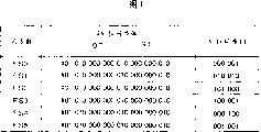
As shown in Figure 4, for example different synchronous mode is used for 6 the different frames FS0 to FS5 of accompanying drawing 4 (promptly).In the example shown in the accompanying drawing 4, the fixed mode that is called sync-body is distributed in 24 positions of beginning that constitute 30 positions of each synchronous mode.Determine by in the position shown in the accompanying drawing 4 according to the value of first anteposition, distribute the fixed mode after the 9T-9T reversal interval of being reversed in subsequently by " 010 " expression.This allows synchronous detection.
Unique 6-bit synchronization ID further distributes to each frame.ID can be used for discerning frame FS0 to FS5 synchronously.
In accompanying drawing 2, synchronous mode detection circuit 20 detects 6 synchronous modes (FS0 to FS5) that are included among the pit modulation signal SD, preserve these patterns in latch 21 as frame number information FN.
Synchronous mode detection circuit 20 also starts reset pulse RS when detecting synchronous mode, and makes the count resets of first counter 22 and second counter 23.Therefore, after testing after the synchronous mode count value of first counter 22 and second counter 23 reset to " 0 " and this value increased progressively.
Second counter 23 begins and increases progressively value the unit of channel clock from count value " 0 ", and makes count value reset to " 0 " when count value reaches predetermined value.In this case, predetermined value is set at " 164 ", and therefore second counter 23 is counters of 165.
First counter 22 adds 1 up when the count value of second counter 23 is overflowed and turn back to " 0 " at every turn.
Therefore, the output PN of first counter 22 resets to " 0 " immediately after synchronous mode, and per then 165 clocks increase by 1.
Reference table 24 comprises that memory storage is such as ROM (ROM (read-only memory)).The frame number information FN that the ROM of reference table 24 storage is carried from latch 21 and according to the reference information 42a of the value output preset selection signal SLCT of the output PN of first counter 22.
Reference table 24 will output to analog switch 28 by the selection signal SLCT of reference reference information 24a output based on frame number information FN and output PN.
The structure that is stored in the reference information 24a in the reference table 24 is hereinafter described.
The second information SB as shown in Figure 1 is input to CRC (cyclic redundancy check (CRC)) adding circuit 25.CRC adding circuit 25 is made of trigger, XOR etc., and the CRC sign indicating number is joined among the input second information SB.
In case receive the second information SB of 32-position, CRC adding circuit 25 increases the CRC sign indicating number of the 16-position that is used for error-detecting.Therefore the second information SB is to have the information of 48 (B0 to B47) altogether.
The CTC sign indicating number that is increased allows error-detecting and the elimination in the process of reading.
48-position copyright protection information (i.e. the second information SB) B0 to B47 with the CRC sign indicating number that is increased is input to string also in (S/P) change-over circuit 26, as shown in Figure 2.
Serial-parallel conversion circuit 26 is made of trigger etc., and the 48-position information of input is exported by turn as 48 parallel output signals.48 output signals are transported in the group of non-conversion amplifier 27A (0 to 47) and conversion amplifier 27B (0 to 47) along separate routes.
Each non-conversion amplifier 27A (0 to 47) output voltage "+Vw " when input signal has logical one, and when input signal has logical zero output voltage " Vw ".
On the contrary, each conversion amplifier 27B (0 to 47) output voltage " Vw " when input signal has logical one, and when input signal has logical zero output voltage "+Vw ".
Therefore, each group of non-conversion amplifier 27A and conversion amplifier 27B be used for each the input 1-position digital signal (B0 to B47) be converted to two simulating signals (+Vw and-Vw).For example, when the second information SB " B0 " has value " 1 ", this value is converted to two simulating signals by the aforesaid operations of non-conversion amplifier 27A-0 and conversion amplifier 27B-0, these simulating signals are exported in the "+Vw " conduct " B0A " that promptly will export and " Vw " conduct " B0B " that will export then.
Voltage Vw directly influences wobble amplitude, and is as mentioned below.In the present embodiment, as mentioned below, the amount of for example swinging displacement is set to 5 nanometers or littler.Regulation voltage Vw to this level in case the swing displacement amount can be 5 nanometers or littler.
Selection is one in the signal that analog switch 28 is imported from non-conversion amplifier 27A (0 to 47) and conversion amplifier 27B (0 to 47) based on the value of the selection signal SLCT that carries from reference table 24.
Selected voltage "+Vw " or " Vw " are as swing command signal SBW output.
Use this structure, additional modulation circuit 7 is selected the position of copyright protection information B0 to B47 according to elapsed time (relative position) from the synchronous mode that is detected by pit modulation signal SD, as mentioned below.One group "+Vw " or " Vw " corresponding to selected position from B0 to B47 also exports as swing command signal SBW.
With reference now to accompanying drawing 5 to 8, is described in the operation that realizes in the former dish making apparatus 1 with structure as described above.
Accompanying drawing 5A, 5B, 5C, 6A, 6B and 6C are depicted as the transition of the value of the selection signal SLCT that selects in the appointment of the analog switch 28 shown in the accompanying drawing 2.Accompanying drawing 5A, 5B, 5C, 6A, 6B and 6C schematically show the frame FS0 to FS6 that constitutes a piece shown in the accompanying drawing 4.
In the present embodiment, at first as indicated above, the 220-byte data is recorded in each frame.Shown in accompanying drawing 5A, 5B, 5C, 6A, 6B and 6C, the information with 220 * 8=1760 position is recorded in each frame, except the synchronous mode part.
In RLL (1-7) PP modulation, the 2-bit data is converted to the 3-bit data.Therefore, each frame has the length of 1760 * 3 a ÷ 2=2640 time clock.
In the frame synchronization that begins to locate of each frame shown in accompanying drawing 5A, 5B, 5C, 6A, 6B and the 6C by detecting in synchronous mode detection circuit shown in the accompanying drawing 2 20.As indicated above, 6 different frames (FS0 to FS5) use in the present embodiment, and the synchronous ID of the frame synchronization that is detected is determined by synchronous mode detection circuit 20.Value by synchronous mode detection circuit 20 determined frame number information FN outputs to reference table 24 from latch 21.
When detecting frame synchronization in mode as indicated above, also output from synchronous mode detection circuit 20 of reset pulse RS, the count value of first counter 22 resets to " 0 ".Therefore, the first counter 22 output PN that will have a value " 0 " outputs to reference table 24.
Response reset pulse RS, the count value of second counter 23 also resets to " 0 ".As indicated above, second counter 23 begins 165 counting according to channel clock.
First counter 22 made count value increase progressively 1 when each second counter 23 reached at last (channel clock changes 165 times).The value of the output PN of first counter 22 per 1 65 clocks in " 2640 " the individual clock corresponding to a frame increase progressively 1.In this case, output PN gets 16 values of 0 to 15 scope, as 1640 ÷ 165=16.
In case receive the output PN of value and from the frame number information FN of latch 21 outputs, then reference table 24 is based on output PN and frame number information FN output preset selection signal SLCT with scope of from 0 to 15.
To constitute a plurality of the precalculated positions of distributing to frame of the second information SB then based on relative time from the sync pattern detection effluxion.
The position has been shown in accompanying drawing 5A, 5B, 5C, 6A, 6B and 6C has distributed, 48 positions (B0 to B47) that wherein constitute the second information SB are distributed to 6 frames (FS0 to FS5) that constitute a piece again.
2 described with reference to the accompanying drawings as mentioned, by non-conversion amplifier 27A and conversion amplifier 27B each position in 48 positions is converted to two simulating signals (output).Therefore, a position is made of two signals.
Distribute to again 48 positions when frame that FS0 begins, shown in accompanying drawing 5A, 16 signals of beginning (being B0A, B0B...B7A and B7B) are distributed to frame FS0.Signal (being B8A, B8B...B15A and B15B) after the B7B is distributed to frame FS1.
Subsequently, signal B16A, B16B...B23A and B23B distribute at the frame FS2 shown in the accompanying drawing 5C, signal B24A, B24B...B31A and B31B distribute at the frame FS3 shown in the accompanying drawing 6A, and signal B32A, B32B...B39A and B39B distribute at the frame FS4 shown in the accompanying drawing 6B, signal B40A, B40B...B47A and B47B distribute at the frame FS5 shown in the accompanying drawing 6C.
2 described with reference to the accompanying drawings as mentioned, reference table 24 is with described mode storage of reference information 24a above, and a plurality of positions that reference information 24a helps to constitute the second information SB are distributed in the precalculated position in each frame.
Be stored in reference information 24a in the reference table 24 and for example have as shown in Figure 8 structure.
In accompanying drawing 8, reference information 24a helps to distribute in the output signal (B0B to B47B) of the output signal (B0A to B47A) of the non-conversion amplifier 27A related with the output PN of the frame number information FN of output from latch 21 and first counter 22 and conversion amplifier 27B.
For with as at this signal of order assignment as shown in accompanying drawing 5A, 5B, 5C, 6A, 6B and the 6C, shown in accompanying drawing 5A, signal B0A when frame number information FN is set at " 0 ", B0B...B7A and B7B distribute to the value " 0 to 15 " of output PN.Signal subsequently distributes according to the value of frame number information FN and the value of output PN again.
Shown in accompanying drawing 5A, 5B, 5C, 6A, 6B and 6C, per subsequently 165 clock selecting B0A, the selection signal SLCT of B0B...B47A and B47B exports from reference table 24.
Owing to change to select the value of signal SLCT, therefore corresponding to the swing command signal SBW output of the simulating signal of the value of the second information SB as output from analog switch 28.Swing command signal SBW is input in the optical deflector shown in the accompanying drawing 19, and according to the direct of travel of this signal change laser beam LO.Therefore, by swing the second information SB is recorded on the former dish 15.
Accompanying drawing 7 is depicted as the synoptic diagram by the operation of recorded in wobbles second information based on swing command signal SBW.
Accompanying drawing 7 is depicted as the have value frame number information FN of " 0 ", promptly will be recorded in the 8-position second information SB among the frame FS0 as shown in accompanying drawing 7 (a).
In accompanying drawing 7, at first, for example, the low level B0 to B7 that supposes the second information SB has as in the value as shown in the accompanying drawing 7 (d).For having value 0 " least significant bit (LSB) " B0 ", 2 described with reference to the accompanying drawings as mentioned, non-conversion amplifier 27A-0 output " Vw " and conversion amplifier 27B-0 export "+Vw ".Therefore, in the swing command signal SBW shown in the accompanying drawing 7 (e) output so that be selected as output " Vw " in period 1 in the value of the selection signal SLTC shown in the accompanying drawing 7 (c) at " B0A ", and output "+Vw " in " B0B " selecteed cycle subsequently.
For second lowest order " B1 " with value " 1 ", non-conversion amplifier 27A-1 output "+Vw " and conversion amplifier 27B-1 output " Vw ".Therefore, be selected as selecting output voltage "+Vw " in cycle of signal SLTC at " B1A ", and in " B1B " selecteed cycle output voltage " Vw ".
Therefore export as swing command signal SBW in the change in voltage shown in the accompanying drawing 7 (e).
Shown in accompanying drawing 7 (e), in the present embodiment, the cycle that equals to export negative voltage (i.e. " Vw ") in cycle to each position output positive voltage (i.e. "+Vw ").This be because, 2 descriptions with reference to the accompanying drawings as mentioned always are converted to two simulating signals with the value of a position by non-conversion amplifier 27A and conversion amplifier 27B, promptly " Vw " and "+Vw " exports these simulating signals then.
Therefore, in the present embodiment, swing is equivalent to carry out on two polarity of positive and negative.This has prevented that tracking servo from changing the position of light beam spot.
As indicated above, be input in the optical deflector shown in the accompanying drawing 19 at the swing command signal SBW shown in the accompanying drawing 7 (e).Optical deflector 9 changes the direct of travel of laser L0 according to swing command signal SBW.Be recorded on the recording surface of former dish 15 pit with the direction superior displacement of the length direction quadrature of track.
Accompanying drawing 7 (f) schematically shows displacement.For example, be chosen as the cycle of selecting signal SLCT signal, output signal "+Vw ", pit train displacement "+Δ " for " B1A ".That is, shown in accompanying drawing 7 (f), selecting in the cycle of " B1A ", pit P1, P2 and P3 in accompanying drawing 7 (f) reference orbit TC in move shift amount " Δ " in the heart.
For selecting " B1B " as the cycle of selecting signal SLCT, output signal " Vw " is as swing command signal SBW, pit train displacement " Δ ".That is, shown in accompanying drawing 7 (f), pit P4, the center of P5 and P6 reference orbit TC in accompanying drawing 7 (f) moves down shift amount " Δ ".
Like this, pit train swings to positive and negative polarity, will be recorded on the former dish 15 as the second information SB of copyright protection information thus, promptly coils on 100.
With reference now to accompanying drawing 9 to 10 describe play that make and have stack and the record first information SA thereon and an optical disc playing device 30 of the dish 100 of the second information SB by former dish making apparatus mentioned above 1.
Accompanying drawing 9 is depicted as the calcspar of conduct according to the example of the inner structure of the optical disc playing device 30 of the embodiment of device for playing disk of the present invention.
In accompanying drawing 9, dish 100 is disc recording mediums of making by former dish making apparatus 1.Be appreciated that from the description of preamble first information SA and the second information SB as copyright protection that indicates the pit train of first information SA to form by swing are recorded on the dish 100.
Tracking error signal TK and focus error signal FS flow to servo circuit 39, and are used to focus of controlling optical pickup 32 etc.Play signal HF flows to binarization circuit 34 and is used as pit modulation signal SD with the information of detection record on dish 100.
Push-pull signal PP flows to low-pass filter (BPF) 40, eliminates undesirable low frequency and high frequency noise components in low-pass filter 40, and the result is flowed to second decoding circuit 41.Second decoding circuit 41 reads by the second information SB of recorded in wobbles on dish 100 based on push-pull signal PP.The inner structure of second decoding circuit 41 is hereinafter described.
The reverse operating that 1-7PP decoding circuit 35 is carried out RLL (1-7) PP modulation to be decoding to the information that is write down, and the result is flowed to ECC circuit 36.
The channel clock CK that is produced flows at the parts shown in the accompanying drawing 9, and as operating clock.
In CRC check circuit 42, if determine that then except CRC sign indicating number (16-position), 32 (representative copyright protection informations) of the beginning of 48 (B0 to B47) flow to decrypt circuit 37 because the result of error checking has correctly read the second information SB.
Therefore, use the encoded first information SA of the second information SB (being copyright protection information) to decode and play in the mode of standard as key.
In CRC check circuit 42, if determine because the result of error checking has comprised error, then first information SA deciphering correctly to encoding.In this case, for example, this situation of reporting system controller (not shown), system controller can control the parts of optical disc playing device 30 so that system reset can detect copyright protection information B0 to B47 once more.
Accompanying drawing 10 is depicted as the calcspar that is used for the example of the inner structure of second decoding circuit 41 of decoding at the second information SB shown in the accompanying drawing 9.
In accompanying drawing 10, be input in the AD converter 50 from the push-pull signal PP that the low-pass filter shown in the accompanying drawing 9 40, carries, and be converted to digital signal.Digital signal postpones preset time by delay circuit 51, and synchronous with binary signal BD.
Be input to synchronous mode (FS) testing circuit 58 at the binary signal BD shown in the accompanying drawing 9.Synchronous mode detection circuit 58 carry out with in synchronous mode detection circuit 20 similar operation shown in the accompanying drawing 2.
Specifically, synchronous mode detection circuit 58 detects 6 synchronous modes (FS0 to FS5) among the binary signal BD that is included in RLL (1-7) PP modulation, and these patterns are retained in the latch 59 as frame number information FN.Synchronous mode detection circuit 58 further starts reset pulse RS in described mode above when detecting synchronous mode, and the count value of first counter 60 and second counter 61 is resetted.
Also be in this case, first counter 60 and second counter 61 reset to " 0 " immediately after synchronous mode, and increase progressively 1.
First counter 60 and second counter 61 are carried out and similar operation in accompanying drawing 2.That is, second counter 61 is counters of 165, and first counter 60 makes count value increase progressively 1 when the count value of second counter 61 resets to " 0 " at every turn.
Reference table 62 also carry out with in the operation similar operation shown in the accompanying drawing 2.Specifically, reference table 62 is exported the predetermined value related with the output PN of the frame number information FN and first counter 60 as selecting signal SLCT.
Also be in this case, select signal SLCT to be input to analog switch 52.Therefore, to select to be input to the signal B0A of analog switch 52, B0B...B47A, a signal among the B47B in the sequential that above 5 the and 6 described sequential that are used for writing down are suitable with reference to the accompanying drawings.
Also be in this case, the reference information that is stored in the reference table 62 is equivalent at the reference information 24a shown in the accompanying drawing 8.
Therefore, for example, when playing " B0A " terminal of in the process of record, being chosen in the analog switch 28 shown in the accompanying drawing 2 regional, appear on " B0A " terminal of analog switch 52 from the output of the push-pull signal PP of delay circuit 51.
Similarly, for example, in the process of record, select and push-pull signal PP that the zone of record " B0B " obtains appears on " B0B " terminal of analog switch 52 by playing.
Therefore, in analog switch 52,48 (each all is converted to two simulating signals in the process of record) obtains based on the push-pull signal PP of input from delay circuit 51.
Conversion equipment 53-0 to 53-47 is converted to B0B to the B47B terminal of analog switch 52 respectively, and the reverse signal of output polarity.
For example, when the least significant bit (LSB) as the second information SB of push-pull signal PP input is " 0 ", with reference to the accompanying drawings 7, the signal of swing " Δ " and "+Δ " obtains on " B0A " and " B0B " of analog switch 52 terminal respectively.Because the above-mentioned operation of conversion equipment 53, "+Δ " swing of " Δ " that obtains on " B0B " terminal and "+Δ " swing oppositely.
Use this conversion operations, when being " 0 ", only obtained signal corresponding to " Δ " in position as the second information SB.When the position as the second information SB is " 1 ", only obtained signal corresponding to "+Δ ".
By adding circuit 54-0 to 54-47 the signal of gained is sued for peace, and the signal of summation is input to digital integrating circuit 55 (0 to 47) respectively.
Each digital integrating circuit 55-0 to 55-47 carries out integration to the signal of carrying from the adding circuit 54 of correspondence.
55 pairs of reverse signals of each digital integrating circuit carry out integration.For example, when having logical zero in the position of record, each integrating circuit 55 is only to the signal integration corresponding to " Δ " swing.Then, digital integrating circuit 55 obtains negative value.On the contrary, for example on the throne when having logical one, obtain on the occasion of.
In the present embodiment, as shown in Figure 7, with the polarity record swing of alternate.Therefore expect the noise component that is included in record and the playing process by on average with the relative less amplitude of result's acquisition as the integration operation of digital integrating circuit mentioned above 55.
Determine that circuit 56 (0 to 47) counts the number of times of the integration carried out in digital integrating circuit 55, and the polarity of the output of the digital integrating circuit 55 of verification correspondence when the number of times of integration surpasses predetermined value.Be output as timing at each digital integrating circuit 55, determine circuit 56 output logics " 1 ".Being output as when negative, determine circuit 56 output logics " 0 ".
The numerical data (B0 to B47) of output flows to parallel-to-serial (P/S) change-over circuit 57 from determine circuit 56, and exports as the second information SB.
In the present embodiment, be set in that each predetermined times of determining the integration in the circuit 56 is determined so that predetermined times n greater than 16.That is, digital integrating circuit 55 repeats above-mentioned integration operation and has imported at least 16 times up to the play signal that for example has identical frame number information FN.
As mentioned before, in this example, the record second information SB in the cycle of 6 frames (a for example piece in accompanying drawing 3).If predetermined value n sets in described mode above, then repeat integration operation up to the push-pull signal PP that has imported at least 16 pieces.
Because each digital integrating circuit 55 is carried out the integration in the cycle of at least 16 pieces, so the optical disc playing device 30 of present embodiment detects reliably by the second information SB of 5 nanometers or littler recorded in wobbles and not influenced by any of noise.
In correlation technique, require the oscillating quantity Δ of at least 20 nanometers.Relative with it, in the present embodiment, the oscillating quantity Δ is set 5 nanometers or littler.In this case, compare with correlation technique, the signal noise ratio of push-pull signal PP (SNR) also is reduced to 1/4 or littler.
Yet because the generation at random of noise, the square root of the value of SNR and the number of times of integration increases pro rata.
In the optical disc playing device 30 of present embodiment, as indicated above, digital integrating circuit 55 is carried out at least 16 integrations, therefore allows to detect the dish with oscillating quantity Δ littler than correlation technique reliably with the SNR that is equal to or higher than the SNR in correlation technique.
In the present embodiment, shown in accompanying drawing 5 to 6, the second information SB distributes and is recorded in the piece, and further is recorded in a plurality of.Therefore, the identical information as the second information SB is recorded on a plurality of that coil on 100.
When the second information SB of record plays by optical disc playing device 30 by this way; if because coming off of causing of the defective etc. of dish, slide in the position etc. causes that a certain frame is not readable, though then defective part still can correctly be play the second information SB (being copyright protection information) as slight noise level reflection.
Therefore, according to present embodiment, the second information SB can be stably and is read reliably and be not subjected to any influence that defective in the tracer signal of dish in 100 or pit are lost.
Therefore, in the present embodiment, in broadcast dish 100, repeatedly integration is repeatedly as the second information SB of recorded in wobbles.Therefore, the swing displacement on dish 100 can be reduced to 5 nanometers or littler.
As indicated above, the second information SB repeatedly is recorded in a plurality of that coil on 100.In the process of playing the second information SB, repeatedly read the identical information of record repeatedly, then to its integration.
Even this has for example guaranteed to begin to have taken place still can play when defective or pit are lost the second information SB as copyright protection information at frame.
Therefore,, can write down the second information SB with the less swing displacement that is equivalent to the swing displacement in the correlation technique according to present embodiment, even and for example frame begin defective or convex region have taken place loses still and can play the second information SB reliably.
Because the second information SB with less oscillating quantity record does not influence tracer signal, therefore can accurately copy first information SA.In other words, though the first information SA of coding can be copied, be difficult to analyze and copy stack and the record second information SB thereon that is used for first information SA decoding.
The copied disc unlawfully because the second information SB can not be copied, therefore this dish can not be play on optical disc playing device 30.This helps only to sell authorized dish, has therefore protected copyright more effectively.
In the above-described embodiment, the present invention for example supports RLL (1-7) PP modulation signal method.Yet this method only is that essence of the present invention can be supported all modulator approaches for example, for example comprises EFM modulation, RLL (8-16) modulation and RLL (2-7) modulation.
To distribute for the position of each frame only be for example to the second information SB in the above-described embodiment, also can use any other position to distribute.
In the above-described embodiment, the second information SB of each alternately is assigned to the positive and negative signal by non-conversion amplifier 27A and conversion amplifier 27B.Yet, for example, also can use pseudo-random number sequence to wait and be assigned to positive and negative polarity.In this case, the complexity of the tracer signal of the second information SB further increases, and therefore makes it be difficult to form pirate copies more.
Industrial applicibility
As indicated above, in the present invention, modulate first digital information to obtain first signal (signal of RLL (1-7) PP modulation) is as the pit train swing of first signal record With with second digital information recording to disc recording medium. Record second digital information so that structure Become a plurality of positions of second digital information to distribute to the identical synchronizing signal that is included in the first signal Unit in the cycle. That is, periodically distribute also in the cycle in the unit of identical synchronizing signal Record consists of a plurality of positions of second digital information.
In the process of playing, periodically a plurality of positions of formation second digital information of record exist Each unit of synchronizing signal was read repeatedly in cycle, and to read the position information carry out integration.
Therefore, in the unit of a plurality of synchronizing signals on the cycle from the pit of a large amount of swings Information can be integrated to determine the value of position. Therefore, second digital information can be stablized and reliably Read and defective or lost efficacy to disc recording medium without any impact.
In addition, according to the present invention, in the process of playing, after carrying out integration, determine formation the The value of the position of two numerical information. Therefore, second digital information can be by the swing of less Record.
Because second digital information can by the recorded in wobbles of less, therefore for example be used Electron microscope is difficult to analyze swing. This can stop second digital information easily to be decoded.
Claims (6)
1, a kind of former dish making apparatus writes down pit train by laser beam radiation to the former dish and writes down first numerical information and further write down second numerical information by swinging this pit train, and said former dish making apparatus comprises:
According to modulate first signal generation device that first numerical information produces first signal by desired form;
According to the relative position that is included in the synchronizing signal in first signal, distribute a plurality of the position selecting arrangement that constitutes second numerical information in the cycle in the unit of identical synchronizing signal; With
Wobble modulations device according to output wobble pits sequence on the positive and negative both direction of position selecting arrangement.
2, a kind of disc manufacturing method of making disc recording medium of making by former dish, wherein write down pit train to the former dish and write down first numerical information and further write down second numerical information, wherein carry out former dish and make by carrying out following step by swinging this pit train by laser beam radiation:
By modulate first signal generation step that first numerical information produces first signal according to desired form;
According to the relative position that is included in the synchronizing signal in first signal, distribute a plurality of the position that constitutes second numerical information to select step in the cycle in the unit of identical synchronizing signal; With
Select the wobble modulations step of output wobble pits sequence on the positive and negative both direction of step according to the position.
3, a kind of device for playing disk comprises:
Be used to obtain first read apparatus of first signal, wherein said first signal is by modulating first numerical information according to desired form, with the length of pit be recorded on the disc recording medium at interval;
Be used to read the second reading device of second numerical information, wherein said second numerical information is recorded into by wobble pits and is superimposed upon on first signal;
According to the relative position that is included in the synchronizing signal in first signal that is read by first read apparatus, second numerical information that is read by the second reading device is carried out a plurality of signal integration devices of integration; With
The output of determining a plurality of signal integration devices is so that definite devices of in the cycle being decoded in a plurality of positions of second numerical information in the unit of each synchronizing signal that is used as second numerical information.
4, device for playing disk according to claim 3, a plurality of integrating gears wherein are provided so as to correspond respectively to the position that constitutes second numerical information and
Each integrating gear is to repeatedly carrying out integration in the cycle of detecting synchronizing signal.
5, device for playing disk according to claim 3, each integrating gear in wherein a plurality of integrating gears is to each position of constituting second numerical information integration 16 times at least.
6, a kind of dish player method comprises:
Acquisition is modulated first numerical information with the length of pit be recorded in first of first signal on the disc recording medium at interval and read step according to desired form;
Read by wobble pits and be recorded into the second reading step that is superimposed upon second numerical information on first signal;
According to be included in the relative position of reading the synchronizing signal in first signal that step reads by first, second numerical information that is read is carried out a plurality of signal integration steps of integration in the second reading step; With
The output of determining a plurality of signal integration steps is so that definite steps of in the cycle being decoded in a plurality of positions of second numerical information in the unit of each synchronizing signal that is used as second numerical information.
Applications Claiming Priority (2)
| Application Number | Priority Date | Filing Date | Title |
|---|---|---|---|
| JP2003000341A JP4273767B2 (en) | 2003-01-06 | 2003-01-06 | Mastering device, disc manufacturing method, disc-shaped recording medium, disc playback device, and disc playback method |
| JP341/2003 | 2003-01-06 |
Related Child Applications (1)
| Application Number | Title | Priority Date | Filing Date |
|---|---|---|---|
| CNB2006101257278A Division CN100429704C (en) | 2003-01-06 | 2003-12-26 | Mastering device, disc manufacturing method, disc-shaped recording medium, disc reproduction device, and disc reproduction method |
Publications (2)
| Publication Number | Publication Date |
|---|---|
| CN1692413A CN1692413A (en) | 2005-11-02 |
| CN1310223C true CN1310223C (en) | 2007-04-11 |
Family
ID=32708768
Family Applications (2)
| Application Number | Title | Priority Date | Filing Date |
|---|---|---|---|
| CNB2003801003115A Expired - Fee Related CN1310223C (en) | 2003-01-06 | 2003-12-26 | Mastering device, disc manufacturing method, disc-shaped recording medium, disc reproduction device, and disc reproduction method |
| CNB2006101257278A Expired - Fee Related CN100429704C (en) | 2003-01-06 | 2003-12-26 | Mastering device, disc manufacturing method, disc-shaped recording medium, disc reproduction device, and disc reproduction method |
Family Applications After (1)
| Application Number | Title | Priority Date | Filing Date |
|---|---|---|---|
| CNB2006101257278A Expired - Fee Related CN100429704C (en) | 2003-01-06 | 2003-12-26 | Mastering device, disc manufacturing method, disc-shaped recording medium, disc reproduction device, and disc reproduction method |
Country Status (10)
| Country | Link |
|---|---|
| US (3) | US7248558B2 (en) |
| EP (1) | EP1475788B1 (en) |
| JP (1) | JP4273767B2 (en) |
| KR (1) | KR101017306B1 (en) |
| CN (2) | CN1310223C (en) |
| AT (1) | ATE533150T1 (en) |
| CA (1) | CA2477424C (en) |
| HK (2) | HK1083919A1 (en) |
| TW (2) | TWI277965B (en) |
| WO (1) | WO2004061832A1 (en) |
Families Citing this family (21)
| Publication number | Priority date | Publication date | Assignee | Title |
|---|---|---|---|---|
| JP4273767B2 (en) * | 2003-01-06 | 2009-06-03 | ソニー株式会社 | Mastering device, disc manufacturing method, disc-shaped recording medium, disc playback device, and disc playback method |
| TWI343049B (en) * | 2003-01-23 | 2011-06-01 | Lg Electronics Inc | Recording medium with an intermittent or alternate wobbled pits and apparatus and methods for forming, recording, and reproducing the recording medium |
| CN1698102A (en) * | 2003-01-23 | 2005-11-16 | Lg电子株式会社 | Recording medium with an optional information and apparatus and methods for forming, recording, reproducing and controlling reproduction of the recording medium |
| KR100952949B1 (en) * | 2003-01-24 | 2010-04-15 | 엘지전자 주식회사 | Method for managing a copy protection information of high density optical disc |
| JP2004253048A (en) * | 2003-02-19 | 2004-09-09 | Fuji Electric Holdings Co Ltd | Master disk for magnetic transfer, its manufacturing method, and magnetic transfer method |
| KR101016988B1 (en) | 2003-02-20 | 2011-02-25 | 코닌클리케 필립스 일렉트로닉스 엔.브이. | Information carrier comprising access information |
| EP1597728B1 (en) | 2003-02-20 | 2012-02-29 | Koninklijke Philips Electronics N.V. | Information carrier comprising access information and dummy information and corresponding reproducing apparatus |
| KR100499586B1 (en) * | 2003-05-20 | 2005-07-07 | 엘지전자 주식회사 | Method for managing a copy protection information of high density optical disc and high density optical disc therof and apparatus for detecting a copy protection information |
| JP2006155694A (en) | 2004-11-25 | 2006-06-15 | Sony Corp | Device and method for evaluating disk signal |
| JP2006202352A (en) * | 2005-01-18 | 2006-08-03 | Sony Corp | Master disk manufacturing equipment, master disk manufacturing method, optical recording medium |
| US20100239088A1 (en) * | 2006-03-13 | 2010-09-23 | Dtr Limited | Method and system for digital content protection |
| US20080019260A1 (en) * | 2006-07-24 | 2008-01-24 | International Business Machines Corporation | Anti-piracy for rom optical disks |
| US20090067316A1 (en) * | 2007-08-30 | 2009-03-12 | Mario Torbarac | Method and system for recordable DVDS |
| JP4521457B2 (en) | 2008-11-28 | 2010-08-11 | 株式会社東芝 | Information transmission system |
| EP2434489A4 (en) | 2009-05-21 | 2012-12-05 | Panasonic Corp | Optical disc reproduction apparatus, optical disc reproduction method, reproduction processing apparatus, and reproduction processing method |
| JP2011023051A (en) | 2009-07-13 | 2011-02-03 | Sony Corp | Information recording device, information playback device, device for producing recording medium, information recording medium and method, and program |
| JP2011060348A (en) | 2009-09-08 | 2011-03-24 | Sony Corp | Information recording device, information reproducing device, recording medium manufacturing device, information recording medium, method, and program |
| JP5834554B2 (en) * | 2011-07-07 | 2015-12-24 | ソニー株式会社 | Optical recording medium |
| JP2014142978A (en) * | 2013-01-22 | 2014-08-07 | Sony Corp | Control device, control method, and master-disc fabricating apparatus |
| CN105096983B (en) * | 2015-07-09 | 2017-11-28 | 清华大学 | Credible CD drive with image watermarking and encryption function |
| CN105096984B (en) * | 2015-07-09 | 2017-11-28 | 清华大学 | Image watermarking and encryption method based on optical storage media |
Citations (3)
| Publication number | Priority date | Publication date | Assignee | Title |
|---|---|---|---|---|
| JPH1166739A (en) * | 1997-08-19 | 1999-03-09 | Seiji Yonezawa | Optical recording carrier, and recording device and reproducing device of optical recording carrier |
| JP2001357533A (en) * | 1999-07-07 | 2001-12-26 | Matsushita Electric Ind Co Ltd | Optical disk, its recorder, recording method and reproducing device |
| JP2002197671A (en) * | 2000-12-26 | 2002-07-12 | Sony Corp | Optical recording medium, recording method of optical recording medium and recorder, and playing-back method of optical recording medium and playing-back device |
Family Cites Families (11)
| Publication number | Priority date | Publication date | Assignee | Title |
|---|---|---|---|---|
| JP3061098B2 (en) * | 1994-02-10 | 2000-07-10 | 日本ビクター株式会社 | Optical disk, optical disk reproducing apparatus, and optical disk recording method |
| JPH09246979A (en) | 1996-03-04 | 1997-09-19 | Hitachi Ltd | Modulation method, modulation device, demodulation method and demodulation means for digital data |
| JP3442945B2 (en) | 1996-10-31 | 2003-09-02 | 株式会社東芝 | Synchronous circuit |
| JP3551727B2 (en) * | 1997-10-21 | 2004-08-11 | ソニー株式会社 | Optical information recording device, optical information recording medium, and optical information reproducing device |
| JP4051515B2 (en) | 1998-12-28 | 2008-02-27 | ソニー株式会社 | Disc recording apparatus, disc recording method, optical disc reproducing device, optical disc reproducing method, optical disc, and signal processing circuit |
| JP2000242929A (en) * | 1998-12-07 | 2000-09-08 | Sony Corp | Method and device for recording/reproducing data and recording medium |
| US6735160B1 (en) * | 1999-07-07 | 2004-05-11 | Matsushita Electric Industrial Co., Ltd. | Optical disc, and recording apparatus, recording method, and reproducing apparatus for the same |
| JP3503930B2 (en) | 1999-08-04 | 2004-03-08 | 株式会社リコー | Demodulation circuit and information recording / reproducing device using the same |
| JP4310885B2 (en) | 2000-05-11 | 2009-08-12 | ソニー株式会社 | Optical disc apparatus, optical disc access method, and optical disc |
| JP4449175B2 (en) | 2000-06-22 | 2010-04-14 | ソニー株式会社 | Optical disc apparatus, optical disc recording method, optical disc, and optical disc reproduction method |
| JP4273767B2 (en) * | 2003-01-06 | 2009-06-03 | ソニー株式会社 | Mastering device, disc manufacturing method, disc-shaped recording medium, disc playback device, and disc playback method |
-
2003
- 2003-01-06 JP JP2003000341A patent/JP4273767B2/en not_active Expired - Fee Related
- 2003-12-26 CA CA2477424A patent/CA2477424C/en not_active Expired - Fee Related
- 2003-12-26 EP EP03768297A patent/EP1475788B1/en not_active Expired - Fee Related
- 2003-12-26 WO PCT/JP2003/016868 patent/WO2004061832A1/en active Application Filing
- 2003-12-26 CN CNB2003801003115A patent/CN1310223C/en not_active Expired - Fee Related
- 2003-12-26 KR KR1020047013256A patent/KR101017306B1/en not_active IP Right Cessation
- 2003-12-26 US US10/504,322 patent/US7248558B2/en not_active Expired - Fee Related
- 2003-12-26 CN CNB2006101257278A patent/CN100429704C/en not_active Expired - Fee Related
- 2003-12-26 AT AT03768297T patent/ATE533150T1/en active
-
2004
- 2004-01-06 TW TW095114181A patent/TWI277965B/en not_active IP Right Cessation
- 2004-01-06 TW TW093100240A patent/TWI268496B/en not_active IP Right Cessation
-
2006
- 2006-03-24 HK HK06103732A patent/HK1083919A1/en not_active IP Right Cessation
-
2007
- 2007-06-18 US US11/764,418 patent/US7596075B2/en not_active Expired - Fee Related
- 2007-07-27 HK HK07108170.8A patent/HK1103848A1/en not_active IP Right Cessation
-
2009
- 2009-07-30 US US12/512,613 patent/US7903522B2/en not_active Expired - Fee Related
Patent Citations (3)
| Publication number | Priority date | Publication date | Assignee | Title |
|---|---|---|---|---|
| JPH1166739A (en) * | 1997-08-19 | 1999-03-09 | Seiji Yonezawa | Optical recording carrier, and recording device and reproducing device of optical recording carrier |
| JP2001357533A (en) * | 1999-07-07 | 2001-12-26 | Matsushita Electric Ind Co Ltd | Optical disk, its recorder, recording method and reproducing device |
| JP2002197671A (en) * | 2000-12-26 | 2002-07-12 | Sony Corp | Optical recording medium, recording method of optical recording medium and recorder, and playing-back method of optical recording medium and playing-back device |
Also Published As
| Publication number | Publication date |
|---|---|
| EP1475788A4 (en) | 2010-01-06 |
| EP1475788B1 (en) | 2011-11-09 |
| KR101017306B1 (en) | 2011-02-28 |
| WO2004061832A1 (en) | 2004-07-22 |
| TW200425102A (en) | 2004-11-16 |
| US20050122889A1 (en) | 2005-06-09 |
| EP1475788A1 (en) | 2004-11-10 |
| US20090285058A1 (en) | 2009-11-19 |
| TWI268496B (en) | 2006-12-11 |
| US20070297318A1 (en) | 2007-12-27 |
| CN1692413A (en) | 2005-11-02 |
| HK1103848A1 (en) | 2007-12-28 |
| US7903522B2 (en) | 2011-03-08 |
| CN100429704C (en) | 2008-10-29 |
| JP4273767B2 (en) | 2009-06-03 |
| KR20050088260A (en) | 2005-09-05 |
| TWI277965B (en) | 2007-04-01 |
| US7596075B2 (en) | 2009-09-29 |
| US7248558B2 (en) | 2007-07-24 |
| CN1917049A (en) | 2007-02-21 |
| JP2004213781A (en) | 2004-07-29 |
| ATE533150T1 (en) | 2011-11-15 |
| HK1083919A1 (en) | 2006-07-14 |
| TW200630980A (en) | 2006-09-01 |
| CA2477424A1 (en) | 2004-07-22 |
| CA2477424C (en) | 2012-07-24 |
Similar Documents
| Publication | Publication Date | Title |
|---|---|---|
| CN1310223C (en) | Mastering device, disc manufacturing method, disc-shaped recording medium, disc reproduction device, and disc reproduction method | |
| CN1299260C (en) | Recording apparatus, recording medium, playback apparatus, recording method and playback method | |
| CN1324569C (en) | Information recording medium, recording apparatus, reproduction apparatus, recording method, and reproduction method | |
| CN1291406C (en) | Optical disc and optical disc drive | |
| CN1755809A (en) | Optical head, optical drive apparatus and method for generating tracking error signal | |
| CN1478271A (en) | Disc driving device and wobble information detection method | |
| CN1476600A (en) | Disc-shaped recording medium disc driving device and method and apparatus for producing disc | |
| CN1956083A (en) | Apparatus for manufacturing information record medium, information recording apparatus and information recording method | |
| CN1327230A (en) | Information recording medium and its recording method and playback method | |
| CN1758355A (en) | Recording-medium evaluation method, recording/reproduction apparatus and recording medium | |
| CN1327228A (en) | Disc driving equipment and method for producing swing information | |
| CN1281213A (en) | Information recording equipment, information recording method, information recording media, information replication device and information replication method | |
| CN1263011C (en) | Information recording disc, recording and/or reproducing device and method | |
| CN100347775C (en) | Multi-level read-only optical disc and method of production | |
| CN1764979A (en) | Optical disc recording apparatus, optical disc recording method, optical disc, optical disc reproducing apparatus, and optical disc reproducing method | |
| CN1853221A (en) | Optical record carrier recording method, optical record carrier and apparatus for writing information | |
| CN1658306A (en) | Multistep read-only optical disk and its making method | |
| CN1455922A (en) | Light spot shaping device and method, light pickup device, and optical disk apparatus | |
| CN1284301C (en) | Digital information signal recording method and recording medium | |
| CN1308951C (en) | Data recording method and medium | |
| CN1534644A (en) | Light disk and light disk apparatus | |
| CN1585975A (en) | Optical recording/reproducing medium, stamper for manufacturing optical recording/reproducing medium, and optical recording/reproducing apparatus | |
| CN1967685A (en) | Manufacturing method of multistage CDROM | |
| CN1838270A (en) | Disk recording apparatus, method, and recording control program | |
| CN1831976A (en) | Converging optical apparatus, optical pickup and optical disc apparatus |
Legal Events
| Date | Code | Title | Description |
|---|---|---|---|
| C06 | Publication | ||
| PB01 | Publication | ||
| C10 | Entry into substantive examination | ||
| SE01 | Entry into force of request for substantive examination | ||
| REG | Reference to a national code |
Ref country code: HK Ref legal event code: DE Ref document number: 1083919 Country of ref document: HK |
|
| C14 | Grant of patent or utility model | ||
| GR01 | Patent grant | ||
| CF01 | Termination of patent right due to non-payment of annual fee |
Granted publication date: 20070411 Termination date: 20151226 |
|
| EXPY | Termination of patent right or utility model |