CN1307352C - A structural formwork member - Google Patents
A structural formwork member Download PDFInfo
- Publication number
- CN1307352C CN1307352C CNB028139828A CN02813982A CN1307352C CN 1307352 C CN1307352 C CN 1307352C CN B028139828 A CNB028139828 A CN B028139828A CN 02813982 A CN02813982 A CN 02813982A CN 1307352 C CN1307352 C CN 1307352C
- Authority
- CN
- China
- Prior art keywords
- structural formwork
- stiffener
- bottom member
- structural
- Prior art date
- Legal status (The legal status is an assumption and is not a legal conclusion. Google has not performed a legal analysis and makes no representation as to the accuracy of the status listed.)
- Expired - Fee Related
Links
Images


Abstract
A structural formwork member is disclosed. The structural formwork member includes a base member in the form of a profiled metal sheet that has parallel ribs (5) and plurality of pans (6) between the ribs. The structural member also includes a strengthening member (71) that is structurally connected to the base member.
Description
Technical field
The present invention relates to structural formwork member, and relate to the composite plate that comprises these structural formwork members.
The invention particularly relates to the structural formwork member that is used to construct composite plate.
Background technology
Main (but not being unique) final use of these structural formwork members is to be configured in the composite plate that forms the floor in the building (this term comprises the parking lot).
Another of these structural formwork members (but be not unique other) final use is to constitute the composite plate that forms vertical wallboard.
A kind of structural formwork member that is used to construct the composite plate that forms building floor comprises:
(a) bottom member of shaping steel plate form, it has the parallel ribs of being separated by chassis (pan); And
(b) stiffener of grid beam form, it is by the portions of top cord element that is positioned at steel plate top and be welded on the rib of portions of top cord element and steel plate and/or the belly chord member element on the chassis forms.
The grid beam can also comprise the bottom cord element parallel with the portions of top cord element.
The example of the composite plate that in Japanese patent application JP-A-4-222739 (Hory corporation) and Australian Patent 707101 (The Broken Hill Proprietary Company Limited), has disclosed the structural formwork member of the above-mentioned type and formed by this member.
Described in Australian Patent 707101 and claimed structural formwork member and on market, sell with trade mark TRUSSDEK by the applicant by the composite plate that these members form.
In the scheme disclosed in Japanese patent application and the Australian Patent, steel plate, portions of top cord element and belly chord member element (and the bottom cord element, if any) limit a series of isolated truss that extend along plate length.
In use, these structural formwork members are laid on the floor support and are fixed thereon sometimes, and cast-in-place concrete is to finish the structure of composite floor board.
Therefore, every composite floor board comprises structural formwork member and is positioned at a layer concrete on the bottom member of structural formwork member.
These structural formwork members can constitute to rest against on the floor support by the end with these modular shuttering elements and extend on the span between the adjacent temporary transient or permanent floor support.
These structural formwork members can also constitute like this: promptly, rest against on the outmost floor support and the mid portion of these modular shuttering elements is rested against on the one or more floor support between the outermost floor support by end, thereby on a plurality of spans between the temporary transient or permanent floor support, extending these modular shuttering elements.
The inventor has carried out extensive studies and development on TRUSSDEK structural formwork member and the TRUSSDEK composite floor board that formed by these members.
A result of this research-and-development activity is that the inventor has made many improvement and invented out a kind of improved structural formwork member the TRUSSDEK structural formwork member.
Summary of the invention
Generally speaking, improvement structural formwork member of the present invention comprises:
(a) bottom member of metal sheet form, this bottom member has relative end and relative side, this bottom member comprises the parallel ribs of longitudinal extension, a plurality of chassis between these ribs, and convex and spill forming section, these forming sections are along the side of bottom member and make that a plurality of structural formwork members can be to be superposed side by side relation setting, wherein said rib is not more than 20% of the height of described stiffener above described chassis at the height above the chassis of described bottom member, and the height and the number of the rib of wherein said bottom member are selected like this: the width of described bottom member is at least 80% of a following width: promptly form described rib and produce the width of the flat board before the described bottom member in flat board; And
(b) at least one stiffener that structurally is connected with bottom member.
Preferably, this metal sheet is a steel plate.
This bottom member can adopt flat type.
This bottom member can adopt the forming board form, and it has along the parallel ribs of the length extension of bottom member and a plurality of chassis between these ribs.
Preferably, described chassis is flat.
This stiffener can be arranged in one of them chassis.
Perhaps, stiffener can be arranged in two adjacent chassis, and strides across the rib between these chassis.
Preferably, the rib of bottom member is little rib.
The applicant finds that little rib obviously helps forming board at the compressed capability that has along plate length in the spherical hogging bending zone.
Usually, be located immediately at be used for the temporary transient of structural formwork member above the permanent support part or near the part of the forming board it have hogging bending.
This is a major issue in the length of span that is supported of the structural formwork member that improves given thickness of slab.
This also is to stride across a major issue in the thickness of slab of structural support members of the given length of span in reduction.
The applicant also finds, little rib makes it possible in the structure of composite plate to use this structural formwork member, and described composite plate will be subjected to obvious compound bending effect, and therefore need carry out sizable reinforcement or along strengthening these composite plates with the horizontal direction prestressing of stiffener.
The applicant finds that also little rib can not cause negative effect to the cutting performance of shearing connector, and these are sheared connector and are used for composite plate is connected support member.
Preferably, the height of these ribs above the chassis is not more than 20mm.
Especially preferred is that the height of these ribs above the chassis is not more than 15mm.
More specifically preferably, the height of these ribs above the chassis is not more than 10mm.
Preferably, these ribs are not more than 20% of the height of stiffener above the chassis at the height above the chassis.
Especially preferred is that these ribs are not more than 15% of the height of stiffener above the chassis at the height above the chassis.
Preferably, the height and the number of these ribs are chosen to like this, thereby the width of forming board is at least 80% of a following width, that is, form rib and form the width of the flat board before this forming board in flat board.
Preferably, the concrete interlocking that the shape of these ribs helps bottom member and is poured on the bottom member and solidifies thereon, thus form composite plate.
Preferably, the longitudinally-extending sides face of bottom member comprises convex and spill forming section, these forming sections make a plurality of structural formwork members to concern setting to be superposed side by side, and the female member of the convex component of a member and adjacent members forms overlap.
Bottom member and stiffener can form the truss that extends along the length of bottom member.
Stiffener can comprise the grid beam, and this grid beam is formed with the belly chord member element that is connected with the rib and/or the chassis of portions of top cord element and bottom member by the portions of top cord member at interval above bottom member.
This grid beam can also comprise the bottom cord element, and these elements are parallel to the portions of top cord element and are connected with belly chord member element.
This stiffener can also adopt the form of being inverted pocket member.
Preferably, this inversion pocket member has a roof and two sides, and these sides are connected with bottom member and roof is positioned at the bottom member top.
Preferably, described pocket member is formed by the rolled metal plate.
Preferably, described pocket member is formed by rolled plate.
Preferably, described rolled plate thickness is 0.6-1.2mm.
More preferably, described rolled plate thickness is 0.6-0.8mm.
Preferably, the height of described pocket member is 80-240mm.
More preferably, the height of described pocket member is 130-240mm.
Preferably, described pocket member is 90-190mm at the width of measuring between being connected of the side of this pocket member and bottom member.
Preferably, the side of described pocket member is upwards assembled towards the top of this pocket member.
Preferably, the side of described pocket member has resupinate flange with the side of improving pocket member and the connection between the bottom member.
Preferably, one or two side of described pocket member comprises pressurized or otherwise is formed into part outside the plane of one or two side, thereby the local buckling of structural formwork member is provided resistance and improves the shear ability of structural formwork member.
Preferably, part in compression is rib or the ripple in described one or two side.
Preferably, the longitudinal direction of the axis of these ribs and bottom member laterally extends.
Preferably, the longitudinal direction of the crest of ripple and trough and bottom member laterally extends.
Preferably, the degree of depth of the ripple of measuring between the bottom of the top of crest and trough is at least 3mm.
Preferably, between the top of adjacent peaks or the wavelength of the ripple of between adjacent trough, measuring be 30-60mm.
Pocket member and bottom member can limit a waterproof space, thus when structure is poured into water-bearing concreae on this member in the composite plate, reduce the lateral deformation of structural formwork member and/or in composite plate for building service for example communication cable access way is provided.
Term " waterproof space " here is understood that, refers to and can not be cast in the space that the water-bearing concreae on the structural formwork member penetrates.
Preferably, this space is filled with fire-resistant or fire proofing.
Preferably, interstitial pocket member inner surface and bottom member surface-coated have fire-resistant or fire proofing.
Preferably, described space comprises damping material.
Perhaps, one or two side of pocket member can comprise opening, and to allow to lead to the inside of pocket member, water-bearing concreae can flow in the space that is limited by pocket member and bottom member during the structure composite plate thus.
Preferably, the side of pocket member comprises the opening of alignment, so that stiffener/electric wire/cable can be arranged to extend laterally across pocket member during the structure composite plate.
Preferably, these openings form and reduce the weaken possibility of this pocket member of these openings.These openings can comprise suitable reinforcing section.
Perhaps, this pocket member can so form, thereby one or more part can be filled with concrete and one or more part can be the space.For example, this pocket member can comprise near opening and the internal partition the end that is positioned at pocket member, and described internal partition so is provided with, thereby concrete can only flow in the end of pocket member.This layout has prevented the obstruction of space for the integrality of the shearing connection of making between composite plate and permanent support beam.
Preferably, this pocket member comprises inside or outer support members at end place and/or along the length of pocket member, is used for preventing this pocket member unstability by the reaction force of transfer function on this pocket member.
Preferably, pocket member also comprises and is installed on the pocket member or by its top fixed chord member element.
This portions of top cord element can be the member of any appropriate.
Preferably, the portions of top cord element is bar or rod or plate.
Preferably, this portions of top cord element is steel pole or rod iron or steel plate.
Preferably, make plate distortion, ripple or punch to improve structural formwork member in composite plate and concrete mechanical interlocked.
For example, can be usually form and make this plate distortion, thereby comprise and turning over and/or the downturned portion branch this plate.
The portions of top cord element can be installed on the pocket member by the parts of any appropriate.
A method is that this portions of top cord element is welded on the bottom of pocket member.
Another method is that the portions of top cord element is adhesive on the bottom of pocket member.
Another method is that employing is installed in the portions of top cord element on the pocket member with the belly chord member element that the portions of top cord element is connected with pocket member.
Another (but be not unique other) method is to adopt one or more supports the portions of top cord element to be installed on the bottom of pocket member, and described support is installed on the pocket member and forms by snap fit or other suitable joint method fixed top chord member element.
Preferably, described support is the saddle form, this saddle has the shank of the pocket member of striding across, and these shanks have inwardly towards projection, and the side of this pocket member have the opening that holds these projections and thus with this saddle fixation on pocket member.
Perhaps, the bottom of described pocket member can form partial closure and fixed top chord member element at least thus.
Preferably, described bottom comprises the lateral part of matching with the portions of top cord element, thereby this portions of top cord element can snap fit become to engage with the bottom.
The bonding strength of portions of top cord element and pocket member is preferred so to be selected, and makes to form inefficacy by in stretching or compression the portions of top cord element being surrendered.
This structural formwork member can comprise bridge member, it is connected with one or two end of structural formwork member, and/or be positioned at one or more positions along the length of structural formwork member so that structural formwork member can be directly passed to temporary transient or permanent support part from stiffener with load.
Comprise the portions of top cord element and form in the situation of belly chord member element of truss that at stiffener this bridge member is the feature of particular importance, but unique anything but with bottom member.Specifically, this feature has considered that the assembly of the belly chord member element of portions of top cord element and formation stiffener is generally the fundamental length unit that repeats along the length of structural formwork member.
Therefore, according to the length of structural formwork member, can be at the stiffener at one or two part place that rests against the modular shuttering element on temporary transient or the permanent support part for the end of unit or along the mid portion (partway) of element length.Similarly, if structural formwork member continues on a plurality of spans, temporary transient or permanent support part place in the middle of then identical situation can appear at.
Because can influence loading transfer between this member and temporary transient or permanent support part in the structure of the stiffener of end that directly rests against the structural formwork member on temporary transient or the permanent support part or pars intermedia office, so above-mentioned situation is tangible.Especially with concrete pouring to this member when forming composite plate, can cause intensity to reduce and the excessive deformation or the local distortion of structural formwork member inferior to the optimal load transmission.
Use bridge member to make it possible in the scope of non-standard length of span situation, use the structural formwork member of typical construction length, and can not hinder the loading transfer between structural formwork member and temporary transient or permanent support part.
This bridge member can be the form of the chord member element that is connected with stiffener.
This chord member element can be the form of framework.
This chord member element can comprise that permission chord member element adjustable ground is connected the parts on the stiffener.
This bridge member can also be the form of the panel that for example formed by sheet metal or plate.
This bridge member can also be the slender member that is connected with the bottom member of the structural formwork member form of beam and plate for example.
This structural formwork member can comprise one or more waterproof spaces, it with adjacent stiffener between a part or a plurality of part of bottom member contact, thereby reduced the lateral deformation of this part when being poured into water-bearing concreae on the structural formwork member.
Above-mentioned space feature promptly, has two specific factors to help the partial response of the bottom member between adjacent stiffener in the lateral deformation (promptly to lower process) of water-bearing concreae loading based on applicant's following understanding.These factors are the weight of the static pressure and the water-bearing concreae of the water in the water-bearing concreae that acts on the bottom member.
Can be excessive and quite obvious on the downside of lower process at structural formwork member, and except the infringement visual appearance, also may influence the installation of decoration and/or building service.In addition, can increase the needed amount of concrete of formation planar surface to lower process.
The applicant has been found that and uses aforesaid space, can be by will be to the stiffener that is positioned at the side, space or its zone from the loading transfer that causes at the water-bearing concreae above the space, thus the negative effect of reduction hydrostatic pressure and weight concrete.
This space needn't be used as structural member.
But the structure that limits the space need have loading transfer that enough rigidity and intensity causes with the water-bearing concreae with the top, space to the stiffener that closes on or its zone.
Preferably, this space is passed on most of width of the part of the bottom member between the adjacent stiffener and is extended.
Preferably, more preferably at least 80% on is extending in 70% of the bottom member between adjacent stiffener part at least in this space.
This structural formwork member can comprise a plurality of isolated spaces of length along the part of the bottom member between adjacent stiffener.
This structural formwork member can also comprise the single space of extending along the length of the part of the bottom member between adjacent stiffener.
This space can be less aspect height, thereby make it possible to utilization structure modular shuttering element in the structure composite plate, therefore these composite plates will be subjected to tangible compound bending effect, need transversely to carry out sizable reinforcement or prestressing to strengthen these composite plates in the direction of stiffener.
This space for example can be limited by the material block that is bonded in or otherwise be fixed on the bottom member.
Preferable material is a for example styrene of lightweight material.
This space for example can also be by being limited by the space that surrounds with lower member: (i) bottom member; (ii) the side of bottom member rib or other are near the side of the suitable structure of the part of the bottom member between adjacent stiffener; And (iii) be positioned at bottom member top and extend across described part and contact the sheet material of adjacent rib or other suitable member.
This space for example can also be by being limited by the space that surrounds with lower member: (i) bottom member and (ii) forming board material, and bent plate for example, it has by the rib of bottom member or the fixing side of other suitable fixed component.
This space can also be for example by limiting by the space that surrounds with lower member: (i) bottom member and (ii) be in pocket member in the attitude of upwards overturning, and the bottom of this pocket member is above bottom member and interstitial top, extend downwards the side of pocket member, and pocket member structurally connects bottom member and interstitial other two sides.
Preferably, this space is filled with fire-resistant or fire proofing.
Preferably, interstitial pocket member inner surface and bottom member surface-coated have fire-resistant or fire proofing.
Preferably, this space comprises damping material.
This structural formwork member can also comprise:
(a) structural member, for example reinforcing bar or the framework made by many reinforcing bars; And
(b) pull bar, they with the structural member mechanical couplings on the part of the bottom member of a structural formwork member or be coupled on the part of bottom member of the adjacent structure modular shuttering element that is in overlapping relation, to reduce the lateral deformation that these parts occur when being poured into water-bearing concreae on the structural formwork member.
This feature relates in particular to those parts between stiffener.
This feature can or be used in combination with it with the replacement of the above-mentioned feature in the waterproof space of opposing.
This feature is based on applicant's following understanding, below two specific factors help the especially bottom member partial response between adjacent stiffener in the lateral deformation (promptly to lower process) that water-bearing concreae loads, promptly act on the static pressure of the water in water-bearing concreae on the bottom member and the weight of water-bearing concreae.
As mentioned above, the applicant has been found that and uses the said structure element by making it possible to and will reducing the negative effect of the static pressure and the weight concrete of water for adjacent stiffener from the loading transfer of water-bearing concreae.
Above-mentioned feature to the situation that wherein is arranged side by side two structural formwork members with overlapping relation particularly (but not being unique) relevant.In these situations, the overlap between two members separates to lower process in response to the part of the bottom member that comprises this overlap easily.
According to the present invention, a kind of composite floor board also is provided, it comprises said structure modular shuttering element and one deck hardened concrete that is positioned on this member.
According to the present invention, a kind of composite plate of vertical wallboard form also is provided, it comprises said structure modular shuttering element and one deck hardened concrete or other the suitable sheet material cast that are positioned on this member.
Description of drawings
Mode with embodiment further specifies the present invention below with reference to accompanying drawings, wherein:
Fig. 1 is based on Fig. 1 of Australian Patent 707101, and is the stereogram of an embodiment of TRUSSDEK structural formwork member;
Fig. 2 is the end-view according to an embodiment of structural formwork member of the present invention;
Fig. 3 is the end-view according to another embodiment of structural formwork member of the present invention;
Fig. 4 is the end-view according to another embodiment of structural formwork member of the present invention;
Fig. 5 is the stereogram according to another embodiment of structural formwork member of the present invention;
Fig. 6 is the sectional drawing along the line 6-6 of Fig. 5;
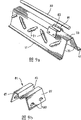
Fig. 7 is the stereogram according to the stiffener of another embodiment of structural formwork member of the present invention;
Fig. 8 is the stereogram according to the stiffener of another embodiment of structural formwork member of the present invention;
Fig. 9 a is the stereogram according to the stiffener of another embodiment of structural formwork member of the present invention;
Fig. 9 b is the stereogram at one of them saddle of the stiffener shown in Fig. 9 a; And
Figure 10 is the end-view according to the stiffener of another embodiment of structural formwork member of the present invention;
Figure 11 is the end-view according to an embodiment of composite floor board of the present invention, and it comprises another embodiment according to structural formwork member of the present invention;
Figure 12 is the end-view according to another embodiment of composite floor board of the present invention, and it comprises another embodiment according to structural formwork member of the present invention;
Figure 13 is the end-view according to another embodiment of composite floor board of the present invention, and it comprises another embodiment according to structural formwork member of the present invention;
Figure 14 is the lateral view according to the end parts of another embodiment that is positioned at the structural formwork member on the floor support of the present invention, and this figure demonstrates an embodiment according to bridge member of the present invention;
Figure 15 is the end-view in the structure shown in Figure 14;
Figure 16 is the lateral view that is similar to Figure 14, demonstrates another embodiment according to bridge member of the present invention;
Figure 17 is the end-view in the structure shown in Figure 16;
Figure 18 be with at the similar lateral view of lateral view shown in Figure 14 and 16, demonstrate another embodiment according to bridge member of the present invention;
Figure 19 is the end-view in the structure shown in Figure 18;
Figure 20 be with at the similar lateral view of lateral view shown in Figure 14,16 and 18, demonstrate another embodiment according to bridge member of the present invention;
Figure 21 is at the end-view of the structure shown in Figure 20 along the line 21-21 in Figure 20; And
Figure 22 is the end-view according to another embodiment of structural formwork member of the present invention; And
Figure 23 is the end-view according to another embodiment of structural formwork member of the present invention.
The specific embodiment
Below to describing at the structural formwork member shown in these accompanying drawings, these structural formwork members can be arranged side by side with overlapping relation and be supported by temporary transient support member or permanent support part (for example girder steel), and are used for making up and comprise these members and be positioned at the concrete composite floor board of one deck on these members.
Fig. 1 is based on Fig. 1 of Australian Patent 707101.This figure demonstrates typical TRUSSDEK structural formwork member 3.
Comprise that at the TRUSSDEK structural formwork member 3 shown in Fig. 1 the bottom member of shaping steel plate form, these shaping steel plates have two parallel ribs 5 and three chassis 6 of extending along the longitudinal direction of shaping steel plate.
The side of this bottom member comprises convex forming section 38 and spill forming section 37, and they are by being inserted into convex forming section 38 in the spill forming section 37, thereby makes adjacent panels to link together with the leakproof overlap.
This TRUSSDEK structural formwork member 3 also comprises two stiffeners that identified by numeral 71 substantially, and these stiffeners extend along the length of bottom member.Each stiffener comprises the grid beam that is formed by following element:
(a) the portions of top cord element 7, and it is parallel to rib 5 and extends; And
(b) a plurality of belly chord member elements 9, they are welded on steel plate and the portions of top cord element 7, and steel plate and portions of top cord element 7 are interconnected.
Chord member element 7,9 is formed by reinforcing bar.
Chord member element 7,9 and bottom member form two truss.
A plurality of improvement that structural formwork member shown in Fig. 2 to 23 has adopted the inventor that the TRUSSDEK modular shuttering element is made.
Structural formwork member shown in Fig. 2 comprises bottom member of dull and stereotyped 6 (rather than forming board) form and the stiffener 71 that is welded on inversion pocket member (rather than the grid beam) form on the flat board.
Each pocket member is formed by rolled plate, and has roof 33 and two inclined sides 35 that are welded on the lower end of bottom member.
These pocket member are structural element, and they are arranged to be supported in the effect of bending, vertical shear and the concentrated force at support member place with bottom member.
In addition, these pocket member and bottom member form a series of waterproof spaces 18.
Be similar at the structural formwork member shown in Fig. 2 at the structural formwork member shown in Fig. 3 and 4.
The portions of top cord element 39 that also comprises the steel plate form that is welded on the pocket member 71 at the stiffener of the structural formwork member shown in Fig. 3 and 4.
In addition, comprise two pocket member 71 that size is different at the structural formwork member shown in Fig. 4.This embodiment demonstrates flexibility of the present invention.
The bottom member that comprises forming board form at the structural formwork member shown in Fig. 5 and 6 with central rib 5 and two chassis 6.
This structural formwork member also comprises two substantially by the stiffener of numeral 31 expressions, and they extend along the length of bottom member.
Each stiffener 31 is arranged in one of them chassis 6 and comprises:
(a) be inverted pocket member, it is formed by rolled plate and has roof 33 and two and is connected inclined side 35 on the bottom member at its lower end; And
(b) the portions of top cord element 39, and it is connected with the bottom 33 of pocket member.
The lower end of the side 35 of this pocket member forms the flange 41 of outside upset, to strengthen and the contacting of shaping steel plate 3.This flange 41 welding and/or gluing or otherwise structurally connect on the bottom member.
Two sides 35 of pocket member comprise along a series of ripples 43 of the length of the side 35 of this pocket member.With reference to Fig. 6, these ripples 43 comprise crest 45 and trough 47.Preferably, the depth D of these ripples 43 is at least 6mm (annotating: with respect to each limit 3mm of plate center line), and the wavelength W of ripple 43 is 30-60mm.Ripple 43 so forms, thereby crest 45 and trough 47 are transverse to the longitudinal direction of bottom member.The purpose of ripple 43 is to provide resistance and raising at the enabling capabilities that supports the reaction position for the transverse projections of modular shuttering element.
Two sides 35 of pocket member comprise opening 47, are used for allowing to lead to the inside of pocket member, and water-bearing concreae can flow in the space that is limited by pocket member and bottom member during the structure composite plate thus, fills this space thus.Opening 47 is in the only about half of place of pocket member height.Preferably, the bottom of opening 47 is higher than the height of rib 5.These openings are shown as slit.Preferably, slit width be not more than pocket member height 40%, and slit length and slit width ratio are not more than 2: 1.Usually, slit width is 45mm, and length is 90mm.Preferably, the pocket member of 20mm is at least arranged so that enough shearing resistances are provided above each slit.
Two sides of pocket member also comprise near a series of apertures 48 that are positioned at the pocket member top, are used for making air to overflow from pocket member when water-bearing concreae flows to pocket member inside by main opening 47.
Portions of top cord element 39 is a square-section reinforcing bar form, and its welds or is adhesive on the bottom 33 of pocket member.Portions of top cord element 39 is spaced apart the height H of pocket member with it above bottom member.
The structure that forms pocket member by rolled plate makes it possible to steel with stiffener and concentrates on the bottom member top as far as possible and rightly steel is supported in this position simultaneously.
Be similar in many aspects at the embodiment shown in Fig. 5 and 6 at the embodiment of the stiffener shown in Fig. 7 31.
For example, comprise rolling pocket member at the embodiment shown in Fig. 7, it has bottom 33 and has the side 35 of outside upset flange 41.
Main difference between these embodiment is that portions of top cord element 39 is circular reinforcing bar form, and it is supported by the belly chord member on the side 35 that is welded on pocket member 40.
Be similar in many aspects at the embodiment shown in Fig. 5 and 7 at the embodiment of the stiffener shown in Fig. 8 31.
For example, comprise rolling pocket member at the embodiment shown in Fig. 8, it has bottom 33 and has the outside upset flange 41 that is formed in the side 35 and the side 35 of opening 47.
There are many differences in these embodiments.
For example, comprise also at the embodiment shown in Fig. 8 and to strengthen rib 51 that this reinforcement rib 51 is subjected to from the plane of the side 35 of pocket member rather than in the extruding of the ripple 43 of the embodiment shown in Fig. 5 and 6.The axis of rib 51 is transverse to the longitudinal extension direction of shaping steel plate 3 (not shown).
In addition, be configured as the keyhole structure, and portions of top cord element 39 has the circular cross-section of cooperation and held and fixed by the keyhole structure in the bottom 33 of the pocket member of the embodiment shown in Fig. 8.
Be similar in many aspects at the embodiment shown in Fig. 5,6 and 8 at the embodiment of the stiffener 31 shown in Fig. 9 a and the 9b.
Main difference between these embodiment is, comprises at the embodiment shown in Fig. 9 a and the 9b portions of top cord element 39 is installed to detachable saddle 61 on the pocket member.These saddles 61 stride across the bottom 33 of pocket member and engage with the side 35 of pocket member at isolated interval along its length.These saddles 61 also comprise semi-circular recesses 63, and they engage by snap fit and hold and fixed top chord member element 39.These saddles 61 by be formed in the shank 67 inwardly towards projection 69 engage with the side 35 of pocket member, and extend into spaced openings (not shown) in the side 35 of pocket member.
In the embodiment shown in Figure 10, portions of top cord element 39 is the plate form on the bottom 33 that is welded on pocket member.Usually, the thickness of plate is 5mm.This plate comprises the upwards upset and the wing 79 that overturns downwards.
In order to strengthen, can to make plate distortion (for example having part), ripple and/or be drilled with the hole in upwards upset shown in Figure 10 and downward upset with concrete mechanical interlocked.
This plate need high lateral stability, big flexible rigidity therein and stretch greatly and the situation of compressed capability in be preferred.
Comprise the bottom member of the shaping steel plate form with a series of ribs 5 and chassis 6 and the stiffener 71 of two grid beam forms at the structural formwork member shown in Figure 11, this stiffener comprises two chord member elements 7, belly chord member element 9 and bottom cord element 8.
Stiffener 71 so is provided with, thereby each stiffener 71 strides across the exterior rib 5 of bottom member, and belly chord member element 9 is welded on two chassis 6 of bottom member.The present invention is not limited to this layout, and extends to as shown in FIG. 5 the wherein whole layout that is arranged in the chassis 6 of stiffener.
The width on chassis, the left side 6 as shown in Figure 11 is chosen as enough wide and the position of left side stiffener is chosen as near the rib 5 that is positioned on that side, thereby there is the space, and make and shear on the girder steel (not shown) of connector (for example take the lead stud, not shown) under being welded on or be fixed on other floor support.
The width on chassis, the right 6 as shown in Figure 11 is chosen as relative narrower, and therefore this right stiffener approaches convex forming section 38.In this layout, in use the right stiffener will be arranged near and support coupling part between the adjacent panels of overlapping (and interlocking) thus thus.
A standard-sized structural formwork member 3 has the stiffener that is formed for the 12mm reinforcing bar by diameter, and so constitute, thereby portions of top cord element 7 is the 120mm place above chassis 6, the distance of the center to center of the belly chord member element 9 of each stiffener is 78mm at their place, bottom, the distance of the center to center of stiffener (promptly, the distance of the center to center of portions of top cord element 7) be 166mm, and left side stiffener is 60mm apart from spill forming section 37.
A kind of standard-sized structural formwork member 3 has rib 5, and it is 50mm for 12mm and roof width above chassis 6 highly.
At the rib shown in Figure 11 5 is little rib.
These ribs 5 are less on the height of the portions of top cord element of the stiffener above the chassis 6.
These ribs 5 at height above the chassis 6 and portions of top cord element 7 relation between the height above the chassis 6 also less.Specifically, aspect above-mentioned standard-sized structural formwork member, described pass be 12mm than 120mm, promptly the height of rib be the portions of top cord element height 10%.
Also comprise a plurality of fixed components 19 in chassis 6 at the structural formwork member shown in Figure 11 3.Fixed component 19 helps bottom member and concrete interlocking, thereby can produce good longitudinal sliding motion resistance between bottom member and concrete, to be used for preventing the vertical separation of bottom member and hardened concrete.In addition, as described below the same, these fixed components can be fixed on the bottom member with helping that the space is formed part 27.
Comprise also that at the structural formwork member shown in Figure 11 3 space in the part that is set in place the bottom member between stiffener 71 forms part 27.
It is the form of inverted pocket member that the space forms part 27, and it has roof 33 and separates and contact with the side 35 of the bottom member of structural support members 3 from roof 33 with two.
The space forms part 27 and is fixed on the bottom member by securing member 19.Specifically, the space forms the size of part 27 and so selects, thereby has interference engagement between space shaped portion 27 and securing member 19.
Selectively, or in addition, this space forms part 27 and securing member 19 and can be provided with projection (not shown) and opening (not shown) so that the space forms the interlocking of part 27 and securing member.
It can be open-ended that this space forms part 27.
Perhaps, this space formation part 27 can be formed with the closed end (not shown).For example, the end of this space formation part 27 can be sealed by insert (for example styrene connector or steel sheet).
When being arranged on the bottom member as shown in fig. 11, the space forms part 27 and bottom member defines a space in the part of the bottom member between stiffener.
The purpose in these spaces is to reduce following negative effect: (i) weight that acts on the static liquid pressure on the bottom member and (ii) form the needed water-bearing concreae of composite plate in time on the part that water-bearing concreae is poured into the bottom member between stiffener 71 and bottom member.
Preferably, these spaces are by taking up space and will achieving this end for stiffener 71 from the loading transfer of the water-bearing concreae that is positioned at the top, space.
These spaces needn't be hollow space.In this respect, related request is that the space is a space that keeps under the weight effect of water-bearing concreae and can not be permeated by water-bearing concreae.
Therefore, the space can by be fixed on the bottom member the solid-state material piece for example styrene limit.
The space also needn't occupy the whole width of the bottom member part between stiffener.Requirement is that extend on most of width of this part in this space.
Form the part composite floor board at the structural formwork member shown in Figure 11.Specifically, this floor comprises structural formwork member, is positioned at a layer concrete 4 and horizontal reinforcement 14 on this member.
Has the basic structure identical at Figure 12 and the structural formwork member 3 shown in 13 with structural formwork member shown in the figure 3.
Main difference between the structural formwork member 3 of Figure 11 and 12 is that the space forms the structure of part 27.Specifically, space formation part 27 is the more shallow relatively space formation part 27 with the twisted plate form of suitable material, and it is arranged to make the opposite flank fixing by fixed component 19.
Use more shallow space to form part 27 and make it possible to utilization structure modular shuttering element 3 in the structure composite plate, this composite plate will be subjected to the compound bending effect.Specifically, the same as shown, more shallow space forms part 27 and makes it possible to horizontal prestressing pipeline and cable 46 are arranged in the composite plate, as exist compound bending do the time spent needed.Though do not demonstrate in Figure 12, still the same as shown in Figure 13, laterally reinforcement 49 can be as the possibility for the horizontal prestressing of employing up and down.More shallow space forms the pipe tunnel 44 that part 27 also makes it possible to be equipped with the facility cable and is arranged in the plate in enough lowlands downwards.
Figure 11 and 12 and the structural formwork member 3 of Figure 13 between main difference be that the member of Figure 13 comprises the 3rd stiffener that strides across intermediate rib 5, therefore do not need the space to form part 27.
Figure 13 also demonstrates the optimum position of the stud 48 of taking the lead, and these bolts can be used for modular shuttering element 3 is fixed on floor support for example on the girder steel (not shown).
Also comprise bridge member at the structural formwork member shown in Fig. 2 to 13 3 at place, one or two end or in position, so that in the use of this member, load optimally passed to temporary transient or permanent support part along the length of structural formwork member.Each embodiment below with reference to Figure 14 to 21 pair of bridge member describes.These bridge members are represented by numeral 11 in these accompanying drawings substantially.
In use, in order to make up the floor:
(a) many structural formwork members are arranged to rest against temporarily or plate support 13 for example on perpendicular walls and the horizontal beam for good and all, and these bridge members 11 make load pass to floor support 13 from stiffener 71; And
(b) with concrete pouring to modular shuttering element and form a plurality of composite floor boards (as shown in Figure 11 to 13).
According to the requirement in any given situation, these structural formwork members can extend and just supported by these floor support 13 at these places, ends striding across on the single span that is adjacent between the plate support 13, perhaps can extend across a plurality of spans and are supported on these places, ends and are supported on along one or more positions of the length of structural formwork member by intermediate floor support member 13 by outermost floor support.
In fact, the span between floor support 13 can be 5m or bigger.Especially in the span of this order of magnitude, importantly to load optimally be passed to floor support 13 from structural formwork member.
Usually, structural formwork member is being constructed away from the place in building place, and is transported to this place.Usually, these stiffeners comprise the elementary cell of the length L (as shown in Figure 14) that repeats along the length of structural formwork member.
According to the length of structural formwork member, the stiffener 71 that in use rests against one or two end place of this member on the floor support 13 can be for end of unit or along (centre) part of the length of a unit.As mentioned above, these all are important consideration items, because can influence loading transfer between structural formwork member and floor support 13 in the structure of the stiffener 71 that directly rests against structural formwork member end on the floor support 13 or pars intermedia office.
More particularly, be lower than intensity reduction and excessive deformation or local distortion that the optimal load transmission can cause structural formwork member, especially with concrete pouring to this member when forming composite floor board.
As Figure 14/15,16/17,18/19 with four embodiment as shown in 20/21 as described in the same, bridge member 11 is connected at least one end of structural formwork member and/or is connected one or more positions between these ends of structural formwork member, thereby makes load optimally to pass to floor support from stiffener 71.
In the situation of the embodiment of Figure 14/15, bridge member 11 is triangle-frames 15 that the length by crooked one section reinforcing bar forms.This framework 15 is welded to connect on structural formwork member 3 by following:
(a) summit 17 of framework 15 is welded on top and the belly chord member element 7,9; And
(b) summit 19,21 of framework 15 is connected with bottom cord element 8.
The position of framework 15 is so selected, thereby in use the bottom 23 of framework 15 is positioned at the top of floor support 13.
The optimum location of framework 15 needs the one or more of cutting and/or curved top portion chord member element 7, bottom cord element 8 and belly chord member element 9.Dotted line by numeral 23 expressions in Figure 14 demonstrates the position of belly chord member element 9 in the structural formwork member that constitutes like this.As can be seen from the figure, for correct positioning framework 15, must cut the top with belly chord member element 7,9 and belly chord member element 9 is bent upwards to contact portions of top cord element 7.
In the situation of the embodiment of Figure 16/17, bridge member 11 comprises:
(a) mounting blocks 29, it has the hollow core that can hold portions of top cord element 7 and can slide into desired position along portions of top cord element 7, be resisted against then on the belly chord member element 9, perhaps push, weld or otherwise be connected on the portions of top cord element 7 in that position;
(b) a pair of chord member element 37, each is connected on the piece 29 and is arranged at place, an end extends downwards from piece 29; And
(c) a pair of bottom cord element 51, they are parallel to the core axis of piece 29 and can be extruded, weld or otherwise be connected to the bottom cord element 8 of modular shuttering element 3.
In the situation of the embodiment of Figure 18/19, bridge member comprises the plate 35 on the soffit on the chassis 6 that a little is welded in modular shuttering element 3.
In the situation of the embodiment of Figure 20/21, bridge member 11 be with in identical triangle-frame structure shown in Figure 14/15 embodiment.In the situation of the embodiment of Figure 20/21, framework 15 so is provided with, thereby the bottom of framework is located at intermediate floor support member 13 tops shown in these figure.
At Figure 22 and the structural formwork member 3 shown in 23 is the basic structure identical with the structural formwork member shown in the described figure in front 3 in many aspects.
Figure 22 and 23 demonstrates the promptly outstanding possibility of lateral deformation of the part that is used for reducing the shaping steel plate between adjacent stiffener downwards.
Figure 22 and 23 demonstrates overlapping structural formwork member.In these situations, the part of the shaping steel plate of being discussed is the adjacent side part of overlapping plates, comprises the convex structure 38 and the concave structure 37 of the overlap 61 that forms plate.
In the layout shown in Figure 22, modular shuttering element comprises the pull bar 65 of interfix that is connected with reinforcing bar 63 with the structural member of reinforcing bar 63 forms that are connected with adjacent stiffener at the opposed end place and at place, end and forms the hook of joint overlap 61.
In the layout shown in Figure 23, structural formwork member comprises the structural member with the frame form of the reinforcing bar 63 that is arranged to Pyramid, and culminating point is positioned at the top of overlap 61, and downward and outward extending reinforcing bar, and the lower end of reinforcing bar 63 abuts against on the rib 5 that is close to stiffener.
In two kinds of layouts shown in Figure 22 and 23, the framework of reinforcing bar 63 and reinforcing bar 63 is given stiffener 71 with loading transfer, the downward distortion of the lap of opposing shaping steel plate when water-bearing concreae being poured on these plates thus.
The foregoing description is the example according to many possibility embodiment of structural formwork member of the present invention.
Can under the situation that does not break away from the spirit and scope of the present invention, make many improvement to described these preferred embodiments of the present invention of reference accompanying drawing.
For example, though will form part 27 in the space shown in Figure 11 and 12 by jointing fastener 19 is fixed on the bottom member of structural formwork member 3, but the present invention is not limited to this, but can extend to the method that these space forming sections is fixed on bottom member of any appropriate.
In addition for example, form though bottom member is described as by steel plate, the present invention is not limited to this, and this bottom member can be formed by the metal or the nonmetals of any appropriate.
Claims (55)
1. a structural formwork member comprises:
(a) bottom member of formed metal plate form, this bottom member has relative end and relative side, this bottom member comprises the parallel ribs of longitudinal extension, a plurality of chassis between these ribs, and convex and spill forming section, these forming sections are along the side of bottom member and make that a plurality of structural formwork members can be to be superposed side by side relation setting, wherein said rib is not more than 20% of the height of described stiffener above described chassis at the height above the chassis of described bottom member, and the height and the number of the rib of wherein said bottom member are selected like this: the width of described bottom member is at least 80% of a following width: promptly form described rib and produce the width of the flat board before the described bottom member in flat board; And
(b) at least one stiffener that structurally is connected with described bottom member.
2. structural formwork member as claimed in claim 1 is characterized in that, the height of described rib above the chassis of described bottom member is not more than 20mm.
3. structural formwork member as claimed in claim 1 is characterized in that, the height of described rib above the chassis of described bottom member is not more than 15mm.
4. structural formwork member as claimed in claim 1 is characterized in that, the height of described rib above the chassis of described bottom member is not more than 10mm.
5. structural formwork member as claimed in claim 1 is characterized in that, the rib of described bottom member is not more than 15% of the height of described stiffener above described chassis at the height above the described chassis.
6. structural formwork member as claimed in claim 1, it is characterized in that, described strengthening part comprises the grid beam, this grid beam by the portions of top cord element that is positioned at bottom member top with form with the described rib of this portions of top cord element and bottom member and/or the belly chord member element that the chassis is connected.
7. structural formwork member as claimed in claim 6 is characterized in that, described grid beam also comprises bottom cord element parallel with described portions of top cord element and that be connected with described belly chord member element.
8. structural formwork member as claimed in claim 1 is characterized in that, described stiffener is for being inverted the pocket member form.
9. structural formwork member as claimed in claim 7 is characterized in that, described inversion pocket member has a roof and two sides, and these sides are connected with the roof member and the bottom is positioned at the bottom member top.
10. structural formwork member, it comprises:
(a) bottom member of metal sheet form; And
(b) at least one stiffener of the inversion pocket member form that structurally is connected with bottom member.
11. structural formwork member as claimed in claim 10 is characterized in that, described bottom member is the flat metal plate form.
12. structural formwork member as claimed in claim 10 is characterized in that, described bottom member is the formed metal plate form and comprises parallel ribs and a plurality of chassis between these ribs of extending along the length of bottom member.
13. structural formwork member as claimed in claim 12 is characterized in that, described rib is little rib.
14., it is characterized in that described pocket member has a roof and two sides as each described structural formwork member in the claim 10 to 13, and described side is connected with bottom member, and the bottom is positioned at roof member top.
15. structural formwork member as claimed in claim 10 is characterized in that, described pocket member is formed by the rolled metal plate.
16. structural formwork member as claimed in claim 15 is characterized in that, described rolling thickness of slab is 0.6-1.2mm.
17. structural formwork member as claimed in claim 15 is characterized in that, described rolling thickness of slab is 0.6-0.8mm.
18. structural formwork member as claimed in claim 10 is characterized in that, the height of described pocket member is 80-240mm.
19. structural formwork member as claimed in claim 10 is characterized in that, the height of described pocket member is 130-240mm.
20. structural formwork member as claimed in claim 10 is characterized in that, described pocket member is 90-190mm in the side of this pocket member to the width of measuring between the connection of bottom member.
21. structural formwork member as claimed in claim 10 is characterized in that, the side of described pocket member has the flange of outside upset, with the side of improving this pocket member and the connection between the bottom member.
22. structural formwork member as claimed in claim 10, it is characterized in that, one or two side of described pocket member comprises pressurized or otherwise is formed into part outside the plane of described one or two side, thereby the local buckling of structural formwork member is provided resistance and improved the shear ability of this structural formwork member.
23. want 22 described structural formwork members, it is characterized in that described part in compression is rib or the ripple in described one or two side as right.
24. structural formwork member as claimed in claim 23 is characterized in that, the axis of described rib and the longitudinal direction of described bottom member laterally extend.
25., it is characterized in that the longitudinal direction of the crest of described ripple and trough and described bottom member laterally extends as claim 23 or 24 described structural formwork members.
26. structural formwork member as claimed in claim 10, it is characterized in that, described pocket member and described bottom member define a waterproof space, are used for reducing the lateral deformation of structural formwork member and/or be used for providing access way in the composite plate of finishing for building service when water-bearing concreae being poured on this member in the structure composite plate.
27. structural formwork member as claimed in claim 10, it is characterized in that, one or two side of described pocket member includes opening, be used for allowing to lead to the inside of described pocket member, water-bearing concreae can flow in the space that is limited by described pocket member and described bottom member during the structure composite plate thus.
28. structural formwork member as claimed in claim 10 is characterized in that, the side of described pocket member comprises the opening of aligning, is used to make stiffener/electric wire/cable to be arranged to extend laterally across described pocket member during the structure composite plate.
29. structural formwork member as claimed in claim 10 is characterized in that, described pocket member also comprises the portions of top cord element, and this portions of top cord element is installed on the described pocket member or by it to be fixed.
30. structural formwork member as claimed in claim 29 is characterized in that, described portions of top cord element is bar or rod or plate.
31. structural formwork member as claimed in claim 30 is characterized in that, turns over and/or the downturned portion branch on described plate has, and is used for improving at composite plate structural formwork member parts and concrete mechanical interlocked.
32. a structural formwork member, it comprises:
(a) bottom member of metal sheet form;
(b) at least one stiffener that structurally is connected with bottom member; And
(c) bridge member, it is connected with one or two end of this stiffener and/or is positioned at along one or more positions of the length of this stiffener, is used for making it possible to directly give temporary transient support member or the permanent support part that is used for this structural formwork member with loading transfer from stiffener.
33. structural formwork member as claimed in claim 32 is characterized in that, described bridge member is the form that is connected the chord member element on the described stiffener.
34. structural formwork member as claimed in claim 33 is characterized in that, described chord member element is the form of framework.
35., it is characterized in that described chord member element comprises permission described chord member element and the adjustable parts that are connected of described stiffener as claim 33 or 34 described structural formwork members.
36. structural formwork member as claimed in claim 32 is characterized in that, described bridging component is the panel-form that is formed by steel disc or steel plate.
37. structural formwork member as claimed in claim 32 is characterized in that, described bridge member is the form of the slender member that is connected with the bottom member of described structural formwork member.
38. structural formwork member as claimed in claim 32, it is characterized in that, described stiffener comprises the grid beam, and this grid beam is formed with the belly chord member element that is connected with described portions of top cord element and described bottom member by the portions of top cord element that is positioned at described bottom member top.
39. structural formwork member as claimed in claim 38 is characterized in that, described grid beam also comprises bottom cord element parallel with described portions of top cord element and that be connected with described belly chord member element.
40. structural formwork member as claimed in claim 32 is characterized in that, described stiffener is for being inverted the form of pocket member.
41. structural formwork member as claimed in claim 40 is characterized in that, described inversion pocket member has a roof and two sides, and described side is connected with described roof member, and the bottom is positioned at the bottom member top.
42. a structural formwork member, it comprises:
(a) bottom member of metal sheet form;
(b) a plurality of stiffeners that structurally are connected with described bottom member;
(c) waterproof space, it contacts with the part of described bottom member between adjacent stiffener, is used to reduce the lateral deformation of this part when water-bearing concreae being poured on the described structural formwork member.
43. structural formwork member as claimed in claim 42 is characterized in that, described space is not as structural member.
44., it is characterized in that described space is being extended as claim 42 or 43 described structural formwork members on most of width of the described bottom member part between the adjacent stiffener.
45., it is characterized in that described space is extended as claim 42 or 43 described structural formwork members at least 70% part of the described bottom member that is positioned at adjacent stiffener.
46. structural formwork member as claimed in claim 42 is characterized in that, comprises a plurality of isolated spaces of length along the part of the bottom member between adjacent stiffener.
47. structural formwork member as claimed in claim 42 is characterized in that, comprises the single space of extending along the length of the part of the bottom member between adjacent stiffener.
48. structural formwork member as claimed in claim 42, it is characterized in that, described space is less aspect height, thereby make it possible in the structure composite plate, use this member, therefore these composite plates will be subjected to tangible compound bending effect, need transversely to carry out sizable reinforcement or prestressing to strengthen this composite plate in the direction of described stiffener.
49. structural formwork member as claimed in claim 42 is characterized in that, described space is limited by material block bonding or that otherwise be fixed on the described bottom member.
50. structural formwork member as claimed in claim 42 is characterized in that, described bottom member is the formed metal plate form, and it has the rib and the chassis between these ribs of longitudinal extension.
51. structural formwork member as claimed in claim 50 is characterized in that, described space is by being limited by the space that surrounds with lower member: (i) described bottom member; The side of (ii) described bottom member rib or other side near the suitable structure of the part of the bottom member between adjacent stiffener; And (iii) be positioned at the sheet material that bottom member top extends across described part and contacts adjacent rib or other suitable member.
52. structural formwork member as claimed in claim 50 is characterized in that, described space is by being limited by the space that surrounds with lower member: (i) described bottom member; And (ii) shaped sheet, it has by the rib of described bottom member and the fixing side of other suitable fasteners.
53. structural formwork member as claimed in claim 50 is characterized in that, described space is also by being limited by the space that surrounds with lower member: (i) described bottom member; And (ii) be in pocket member in the attitude of upwards overturning, the bottom of this pocket member is positioned at the top and the interstitial top of described bottom member, and extend downwards the side of this pocket member and structurally with on described bottom member and two sides in addition that form this space be connected.
54. a composite floor board, it comprises structural formwork member as claimed in claim 1 and one deck hardened concrete that is positioned on this member.
55. the composite plate of a vertical wallboard form, it comprises structural formwork member as claimed in claim 1 and one deck hardened concrete or other the suitable sheet material cast that are positioned on this member.
Applications Claiming Priority (5)
| Application Number | Priority Date | Filing Date | Title |
|---|---|---|---|
| AUPR5604A AUPR560401A0 (en) | 2001-06-12 | 2001-06-12 | A structural formwork member |
| AUPR5604 | 2001-06-12 | ||
| AUPS0937 | 2002-03-06 | ||
| AUPS0937A AUPS093702A0 (en) | 2002-03-06 | 2002-03-06 | A structural formwork member |
| PCT/AU2002/000754 WO2002101168A1 (en) | 2001-06-12 | 2002-06-11 | A structural formwork member |
Publications (2)
| Publication Number | Publication Date |
|---|---|
| CN1527899A CN1527899A (en) | 2004-09-08 |
| CN1307352C true CN1307352C (en) | 2007-03-28 |
Family
ID=32231620
Family Applications (1)
| Application Number | Title | Priority Date | Filing Date |
|---|---|---|---|
| CNB028139828A Expired - Fee Related CN1307352C (en) | 2001-06-12 | 2002-06-11 | A structural formwork member |
Country Status (4)
| Country | Link |
|---|---|
| EP (1) | EP1421241A1 (en) |
| CN (1) | CN1307352C (en) |
| HK (1) | HK1066255A1 (en) |
| TW (1) | TWI247841B (en) |
Families Citing this family (4)
| Publication number | Priority date | Publication date | Assignee | Title |
|---|---|---|---|---|
| CN102134906A (en) * | 2011-03-02 | 2011-07-27 | 天津市建科机械制造有限公司 | Truss in integral type framework structure |
| CN103046679B (en) * | 2013-01-22 | 2014-09-03 | 江苏银环新型建材科技有限公司 | Reinforcement steel bar template for concrete molding |
| AU2013206540B1 (en) * | 2013-06-26 | 2014-09-11 | Inhabit Studio Limited | An edge-formwork element with integrated channel |
| CN108894422A (en) * | 2018-07-12 | 2018-11-27 | 华南理工大学 | Assembled Profiled Steel Sheet and Concrete Composite Floor and construction method |
Citations (8)
| Publication number | Priority date | Publication date | Assignee | Title |
|---|---|---|---|---|
| CA704842A (en) * | 1965-03-02 | E. Curran Bernard | Composite floor construction utilizing metal cellular flooring and concrete | |
| AU1262070A (en) * | 1970-03-16 | 1971-09-23 | HENRY LIVINGSTON BURN, KENNETH CAMPBELL GRIFFIES and FREDERICK JOHN BROOKMAN | Load carrying panel |
| AU426485B2 (en) * | 1969-05-13 | 1971-11-11 | Civil & Civic Pty. Limited | Improvements in reinforced concrete constr tion |
| AU4882172A (en) * | 1972-11-16 | 1974-05-16 | Burn H L | Tridetic floor system |
| GB2060730A (en) * | 1979-09-15 | 1981-05-07 | Tinsley Building Prod Ltd | Concrete floors |
| WO1997017509A1 (en) * | 1995-11-09 | 1997-05-15 | Germix Oy | Composite slab, a profile plate thereof and a method for producing a composite slab |
| AU707101B2 (en) * | 1995-01-06 | 1999-07-01 | Broken Hill Proprietary Company Limited, The | A structural member |
| JPH11192613A (en) * | 1997-12-29 | 1999-07-21 | Nkk Corp | Steel base formwork and floor plate |
-
2002
- 2002-06-11 CN CNB028139828A patent/CN1307352C/en not_active Expired - Fee Related
- 2002-06-11 EP EP02726025A patent/EP1421241A1/en not_active Withdrawn
- 2002-06-11 TW TW91112692A patent/TWI247841B/en not_active IP Right Cessation
-
2004
- 2004-11-24 HK HK04109270A patent/HK1066255A1/en not_active IP Right Cessation
Patent Citations (8)
| Publication number | Priority date | Publication date | Assignee | Title |
|---|---|---|---|---|
| CA704842A (en) * | 1965-03-02 | E. Curran Bernard | Composite floor construction utilizing metal cellular flooring and concrete | |
| AU426485B2 (en) * | 1969-05-13 | 1971-11-11 | Civil & Civic Pty. Limited | Improvements in reinforced concrete constr tion |
| AU1262070A (en) * | 1970-03-16 | 1971-09-23 | HENRY LIVINGSTON BURN, KENNETH CAMPBELL GRIFFIES and FREDERICK JOHN BROOKMAN | Load carrying panel |
| AU4882172A (en) * | 1972-11-16 | 1974-05-16 | Burn H L | Tridetic floor system |
| GB2060730A (en) * | 1979-09-15 | 1981-05-07 | Tinsley Building Prod Ltd | Concrete floors |
| AU707101B2 (en) * | 1995-01-06 | 1999-07-01 | Broken Hill Proprietary Company Limited, The | A structural member |
| WO1997017509A1 (en) * | 1995-11-09 | 1997-05-15 | Germix Oy | Composite slab, a profile plate thereof and a method for producing a composite slab |
| JPH11192613A (en) * | 1997-12-29 | 1999-07-21 | Nkk Corp | Steel base formwork and floor plate |
Also Published As
| Publication number | Publication date |
|---|---|
| CN1527899A (en) | 2004-09-08 |
| HK1066255A1 (en) | 2005-03-18 |
| EP1421241A1 (en) | 2004-05-26 |
| TWI247841B (en) | 2006-01-21 |
Similar Documents
| Publication | Publication Date | Title |
|---|---|---|
| KR101144586B1 (en) | Steel built-up beam having closed section for applying long span and reduction of height and concrete filled composite beam system using the same | |
| KR101816142B1 (en) | Girder-plate type bridge using arch-shape composite girder and construction method thereof | |
| AU2002256575B2 (en) | A structural formwork member | |
| AU2002256575A1 (en) | A structural formwork member | |
| US20070000197A1 (en) | Structural decking system | |
| CN108291401B (en) | Support beam for ceiling system, ceiling system and method for manufacturing the same | |
| EP2076637B1 (en) | Building floor structure comprising framed floor slab | |
| EP2689075B1 (en) | System for reinforcing concrete slabs | |
| CN1307352C (en) | A structural formwork member | |
| KR100343960B1 (en) | Steel concrete structure | |
| KR101105404B1 (en) | Deck plate system using cap plate | |
| CN217517829U (en) | Connecting structure for building prefabricated floor and roof board | |
| CN109853873A (en) | Overlap concrete bidirectional stress insulation roof slab | |
| JP5047060B2 (en) | Synthetic floor slab and its reinforcement method | |
| KR102129130B1 (en) | Composite deck plate for adhering z-shaped latticed bar, and manufacturing method for the same | |
| JP4293696B2 (en) | Construction method of composite floor slab bridge | |
| RU2380494C1 (en) | Butt joint of precast concrete columns with solid flooring | |
| CN211007246U (en) | Novel steel bar structure of connecting node of structural beam and full prefabricated slab | |
| CN216865715U (en) | Connection structure of integral seam of coincide floor shaped steel net piece combination | |
| KR102120665B1 (en) | Composite deck plate for integrating web of latticed bar and web of deck plate, and manufacturing method for the same | |
| CN209924269U (en) | Combined beam using aerated concrete blocks | |
| CN216360844U (en) | Prefabricated assembled multi-limb steel reinforced concrete beam | |
| CN217500567U (en) | Connection structure of closed profiled sheet composite floor and steel reinforced concrete beam | |
| CN211645941U (en) | Precast concrete beam and concrete slab combination beam with built-in steel plate | |
| CN215716414U (en) | One-way close rib composite floor |
Legal Events
| Date | Code | Title | Description |
|---|---|---|---|
| C06 | Publication | ||
| PB01 | Publication | ||
| C10 | Entry into substantive examination | ||
| SE01 | Entry into force of request for substantive examination | ||
| REG | Reference to a national code |
Ref country code: HK Ref legal event code: DE Ref document number: 1066255 Country of ref document: HK |
|
| C14 | Grant of patent or utility model | ||
| GR01 | Patent grant | ||
| C19 | Lapse of patent right due to non-payment of the annual fee | ||
| CF01 | Termination of patent right due to non-payment of annual fee |