CN1297378C - Debarking shaft for a debarking mechanism - Google Patents
Debarking shaft for a debarking mechanism Download PDFInfo
- Publication number
- CN1297378C CN1297378C CNB028079477A CN02807947A CN1297378C CN 1297378 C CN1297378 C CN 1297378C CN B028079477 A CNB028079477 A CN B028079477A CN 02807947 A CN02807947 A CN 02807947A CN 1297378 C CN1297378 C CN 1297378C
- Authority
- CN
- China
- Prior art keywords
- debarking
- trees
- tooth
- debarking shaft
- shaft
- Prior art date
- Legal status (The legal status is an assumption and is not a legal conclusion. Google has not performed a legal analysis and makes no representation as to the accuracy of the status listed.)
- Expired - Lifetime
Links
- 239000002023 wood Substances 0.000 claims abstract description 4
- 238000000034 method Methods 0.000 claims description 23
- 230000032258 transport Effects 0.000 claims 1
- 241001014327 Anodontia Species 0.000 description 3
- 206010002583 anodontia Diseases 0.000 description 3
- 230000005212 anodontia Effects 0.000 description 3
- 230000000694 effects Effects 0.000 description 1
- 230000014509 gene expression Effects 0.000 description 1
- 230000002441 reversible effect Effects 0.000 description 1
- 239000007787 solid Substances 0.000 description 1
Images


Classifications
-
- B—PERFORMING OPERATIONS; TRANSPORTING
- B27—WORKING OR PRESERVING WOOD OR SIMILAR MATERIAL; NAILING OR STAPLING MACHINES IN GENERAL
- B27L—REMOVING BARK OR VESTIGES OF BRANCHES; SPLITTING WOOD; MANUFACTURE OF VENEER, WOODEN STICKS, WOOD SHAVINGS, WOOD FIBRES OR WOOD POWDER
- B27L1/00—Debarking or removing vestiges of branches from trees or logs; Machines therefor
- B27L1/10—Debarking or removing vestiges of branches from trees or logs; Machines therefor using rotatable tools
-
- B—PERFORMING OPERATIONS; TRANSPORTING
- B27—WORKING OR PRESERVING WOOD OR SIMILAR MATERIAL; NAILING OR STAPLING MACHINES IN GENERAL
- B27L—REMOVING BARK OR VESTIGES OF BRANCHES; SPLITTING WOOD; MANUFACTURE OF VENEER, WOODEN STICKS, WOOD SHAVINGS, WOOD FIBRES OR WOOD POWDER
- B27L1/00—Debarking or removing vestiges of branches from trees or logs; Machines therefor
- B27L1/02—Debarking or removing vestiges of branches from trees or logs; Machines therefor by rubbing the trunks against each other; Equipment for wet practice
Landscapes
- Life Sciences & Earth Sciences (AREA)
- Engineering & Computer Science (AREA)
- Wood Science & Technology (AREA)
- Forests & Forestry (AREA)
- Debarking, Splitting, And Disintegration Of Timber (AREA)
- Catching Or Destruction (AREA)
- Connection Of Plates (AREA)
- Automatic Assembly (AREA)
- Forging (AREA)
- Solid-Sorbent Or Filter-Aiding Compositions (AREA)
Abstract
The invention relates to a debarking shaft (3) for a debarking mechanism (1), said debarking mechanism being intended for the decortication or pretreatment of trees (2) for separately performed final barking and for the expulsion of at least some of the removed barks from a wood flow passing through the debarking mechanism, said debarking mechanism comprising a number of rotatable debarking shafts (3) extending parallel to the advancing direction of the trees (2) to be fed therethrough and provided with a number of teeth (4) extending beyond the circumferential surface of the shaft (3) and adapted to strip bark off the presently processed trees (2) transversely to the lengthwise direction of the trees and at the same to convey the trees transversely relative to said shafts (3), and said shafts (3), together with the teeth (4) thereof, being adapted to constitute at least a part of a support surface, upon which the presently processed trees (2) travel through the debarking mechanism (1). The debarking shaft (3) has its teeth (4) designed as a number of annular tooth rims (20), each of said tooth rims comprising two or more releasably connected elements (21, 22), having the outer periphery provided with the teeth (4) and said elements being adapted to be fitted around a body member (25) of the debarking shaft (3) by way of press clamping.
Description
Technical field
The present invention relates to a kind of peeling procedure, more specifically, relate to a kind of debarking shaft that is used for a peeling procedure.Described peeling procedure is used to the last peeling of carrying out separately to carry out peeling or the preliminary treatment of trees and be used for from removing the bark that at least some are peeled off through the wood flow of peeling procedure, described peeling procedure comprises that a plurality of edges are parallel to direction of feed that trees are sent to and extend and be provided with a plurality of rotatable debarking shafts that extend to the tooth that extends outside the circumferential surface of described axle, described tooth is applicable to along the processed trees peeling of the horizontal alignment of the length direction of trees with simultaneously with respect to the horizontal transhipment trees of described axle, and described axle and its tooth are suitable for constituting just processed trees together and advance thereon through surface-supported at least a portion of described peeling procedure.
Background technology
The peeling procedure of the above-mentioned type is known in United States Patent (USP) 4685498 and 5394912 for example.
In the peeling procedure of the above-mentioned type, described tooth is fixedly mounted on some position usually.In one application, can replace single tooth, even but under the sort of situation, the position of a tooth on the described axle always remains unchanged.
Summary of the invention
An object of the present invention is to provide a kind of debarking shaft that is used for a peeling procedure, its feature in, one has the tooth of tooth debarking shaft is reversible about the direction of rotation of axle not only, can also easily be moved and replace.
Another object of the present invention is tooth can be moved with the position that arrives a hope and in this position at axial and circumferential make its locking or clamping.
According to the present invention, can realize these purposes by a kind of debarking shaft of the present invention, described axle is characterised in that, it has the tooth that is designed to a plurality of annular gear rings, wherein, each described gear ring comprises two or more attaching parts of unclamping, and they have the outer rim that is provided with tooth, and described parts are applicable to by extruding and are clamped and installed in around the main part of described debarking shaft.
Described gear ring parts preferably are provided with the clamping structure on the main part that makes these parts lean against debarking shaft toward each other.Described clamping structure for example may comprise that one one end is provided with left hand thread and the other end is provided with the headless screw of right-handed thread, and the gripping section that is used to screw described headless screw between screw thread.
Described debarking shaft preferably is made of a round tube.Therefore, this easily can be locked or be clamped in to the adjacent gear ring that is positioned on the same axle upward in the position, any angle that the axle direction of rotation differs from one another, the tooth of described adjacent gear ring can make axle have for example helical structure (helixes).Similarly, can adjust axial relative distance between the gear ring on the same axle on request.
The main part of described debarking shaft is provided with one and is used for the preferably key of guide gear delineation position and the guide structure of groove, and this guide structure is preferably used for each gear ring.
The main part of described debarking shaft is preferably designed so that its cross section is a polygon, thus, can easily guide described gear ring and it is clamped in position, various angle.
Described tooth is preferably designed so that two direction of rotation at debarking shaft all are effective.Can differ from one another or similar at all effective described tooth of opposite direction of rotation.When opposite direction of rotation is used different teeth, different direction of rotation will cause different peeling abilities, for example, be used for the peeling in winter and will be used for the peeling in summer.Also can use sharp tooth to remove the peel to give trees difficult peeling at the beginning or that freeze, and the trees that the tooth of use wearing and tearing peels easily with processing.As long as by getting next gear ring and after with its upset, just reinstalling again and can replace.
Also can be by forming the anodontia some effects peeling of one or more gear rings ability.Therefore, some gear rings on the debarking shaft may be anodontia wholly or in part.
Description of drawings
Describe the present invention referring now to accompanying drawing, wherein:
Fig. 1 illustrates the schematic side elevation that is used for the debarking shaft of a peeling procedure of the present invention;
Fig. 2 illustrates a sectional view along the line II-II direction among Fig. 1;
Fig. 3 illustrates a sectional view along the line III-III direction among Fig. 2;
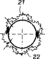
Fig. 4 illustrates a sectional view along the line IV-IV direction among Fig. 3;
Fig. 5 illustrates a sectional view along the line V-V direction among Fig. 3.
The specific embodiment
A peeling procedure 1 shown in the figure is used to the last peeling of carrying out separately to carry out peeling or the preliminary treatment of trees 2 and be used for from removing the bark that at least some are peeled off through the wood flow of peeling procedure.
Described peeling procedure 1 is provided with a plurality of edges and is parallel to the rotatable debarking shaft 3 that direction of feed that trees 2 are sent to is extended.In this illustrated example, every end of described debarking shaft 3 all is provided with sprocket wheel 6, and wherein, at least one end of described peeling procedure 1, described sprocket wheel 6 interconnects and is connected on the gear of a unshowned electro-motor by a sprocket chain (not shown).
Described debarking shaft 3 is provided with a plurality of teeth 4 that extend to outside the circumferential surface of described axle 3, and described tooth is applicable to along the horizontal alignment of the length direction of trees 2 in the trees peeling of processing with simultaneously with respect to the horizontal transhipment trees of described debarking shaft 3.
Described debarking shaft 3 and its tooth 4 constitutes together support log 2 pass through described peeling procedure 1 a surface-supported part.This illustrated example comprises four debarking shafts 3 that assemble each other to form a clinoplain.In addition, described stayed surface also comprises solid object surface, and the stayed surface that described integral surface is designed to constitute with described debarking shaft provides an open-ended skewed slot that covers described peeling procedure 1 through and through together.
The tooth 4 of described debarking shaft 3 is designed to as the clearest a plurality of annular gear rings 20 that illustrate among Fig. 3 and Fig. 4.In the example of Fig. 4, but each gear ring 20 comprises two attaching parts that can unclamp 21,22, and their outer rim is provided with tooth 4.Described parts 21,22 be applicable to by extruding be clamped and installed in described debarking shaft 3 main part 25 around.
These parts 21,22 that make that the parts 21,22 of described gear ring 20 preferably are provided with usually with reference number 23 expressions lean against clamping structure on the main part 25 of debarking shaft 3 toward each other.
In the example of Fig. 4, described clamping structure 23 comprises that one one end is provided with left hand thread and the other end is provided with the headless screw of right-handed thread, and the gripping section 24 that is used to screw described headless screw between screw thread.Described parts 21 and 22 are provided with the screw thread that matches, and can screw described gripping section 24 thus so that parts 21,22 are close to each other or separately.
The cross section of the described main part 25 of debarking shaft 3 is circular, and this main part preferably is made of a round tube.Main part 25 can be used to guide gear ring 20 to the preferably key in its precalculated position and the guide structure (not shown) of groove for each gear ring 20 is provided with one.
It is a polygon that the main part 25 of described debarking shaft 3 also can be designed to its cross section, can easily guide described gear ring that it is clamped with the position, various angle with respect to main part 25 thus.
According to the example among Fig. 4, described tooth 4 can be designed to can work in two direction of rotation of debarking shaft 3.Effective tooth 4 may be shown in different direction of rotation as the example among Fig. 4 and differ from one another, or mutually the same.Select different profiles of tooth may influence the peeling ability that can obtain.Be installed in the position, angle that differs from one another by tooth 4 and may influence peeling (ability) equally adjacent gear ring 20.One or more in the gear ring 20 also can be anodontia (not shown).
Each end of described debarking shaft 3 all is provided with than the axle journal 8 of minor diameter and sprocket wheel 6, wherein, the bearing race (bearing cup) 9 of bearing and bearing is installed on axle journal.Can utilize screw 11 with bearing race 9 fix in position on the end plate 10 of the end of the described peeling procedure 1 that is consistent with described debarking shaft 3.End plate 10 has a top edge that is provided with the top end opening groove 12 of the axle journal 8 that is used for debarking shaft 3, thus, if necessary, can easily by top passageway described axle 3 be carried away.
Claims (1)
- A kind of debarking shaft (3) that is used for a peeling procedure (1), described peeling procedure is used to the last peeling of carrying out separately to carry out peeling or the preliminary treatment of trees (2) and be used for from removing the bark that at least some are peeled off through the wood flow of peeling procedure, described peeling procedure comprises that a plurality of edges are parallel to the tooth (4) outside a plurality of circumferential surfaces that extend to described axle (3) is extended and be provided with to trees (2) by the direction of feed of being sent to by it rotatable debarking shaft (3), described tooth is applicable to along the processed trees of the horizontal alignment of the length direction of trees (2) peeling and laterally transports trees with respect to described axle (3) simultaneously, and described axle (3) and its tooth (4) are suitable for constituting just processed trees (2) together and advance on it through surface-supported at least a portion of described peeling procedure (1), it is characterized in that, the tooth (4) of described debarking shaft (3) is designed to a plurality of annular gear rings (20), each described gear ring comprises two or more attaching parts (21 of unclamping, 22), have the outer rim that is provided with tooth (4), and described parts be applicable to be clamped and installed in described debarking shaft (3) by extruding a main part (25) on every side.A kind of axle according to claim 1 is characterized in that the parts (21,22) of described gear ring (20) are provided with the clamping structure (23) on the main part (25) that makes these parts (21,22) lean against debarking shaft (3) toward each other.A kind of axle according to claim 2, it is characterized in that, described clamping structure (23) comprises that one one end is provided with left hand thread and the other end is provided with the headless screw of right-handed thread, and the gripping section that is used to screw described headless screw (24) between screw thread.A kind of axle according to claim 1 is characterized in that the main part (25) of described debarking shaft (3) is made of a round tube.A kind of axle according to claim 1 is characterized in that, the main part (25) of described debarking shaft (3) is provided with a guide structure that is used for guide gear delineation position for each gear ring (20).A kind of axle according to claim 5 is characterized in that described guide structure is a key and groove.A kind of axle according to claim 1 is characterized in that the cross section that the main part (25) of described debarking shaft (3) is designed to it is a polygon.A kind of axle according to claim 1 is characterized in that two direction of rotation that described tooth (4) is designed at described debarking shaft (3) all are effective.A kind of axle according to claim 1 is characterized in that, differs from one another at all effective described tooth of the opposite direction of rotation of described debarking shaft (3) (4).A kind of axle according to claim 1 is characterized in that, and is mutually the same at all effective described tooth of the opposite direction of rotation of described debarking shaft (3) (4).A kind of axle according to claim 1 is characterized in that described gear ring (20) has one or more no toothed portions.
Applications Claiming Priority (2)
| Application Number | Priority Date | Filing Date | Title |
|---|---|---|---|
| FI20010756A FI112181B (en) | 2001-04-11 | 2001-04-11 | Barking shaft for barking device |
| FI20010756 | 2001-04-11 |
Publications (2)
| Publication Number | Publication Date |
|---|---|
| CN1501854A CN1501854A (en) | 2004-06-02 |
| CN1297378C true CN1297378C (en) | 2007-01-31 |
Family
ID=8560968
Family Applications (1)
| Application Number | Title | Priority Date | Filing Date |
|---|---|---|---|
| CNB028079477A Expired - Lifetime CN1297378C (en) | 2001-04-11 | 2002-02-15 | Debarking shaft for a debarking mechanism |
Country Status (11)
| Country | Link |
|---|---|
| CN (1) | CN1297378C (en) |
| AT (1) | AT413964B (en) |
| BR (1) | BR0208819B1 (en) |
| CA (1) | CA2438614C (en) |
| DE (1) | DE10296635B4 (en) |
| ES (1) | ES2242519B1 (en) |
| FI (1) | FI112181B (en) |
| NO (1) | NO322544B1 (en) |
| RU (1) | RU2253565C2 (en) |
| SE (1) | SE526114C2 (en) |
| WO (1) | WO2002083382A1 (en) |
Families Citing this family (11)
| Publication number | Priority date | Publication date | Assignee | Title |
|---|---|---|---|---|
| FI117378B (en) * | 2004-04-20 | 2006-09-29 | Andritz Oy | Debarking Device |
| FI119283B (en) * | 2004-04-20 | 2008-09-30 | Andritz Oy | Stripping tool |
| CA2629826C (en) * | 2008-04-24 | 2015-10-06 | Realsearch Inc. | Flexible debarking abrader |
| DE102009021802A1 (en) | 2009-05-18 | 2010-11-25 | Pallmann Maschinenfabrik Gmbh & Co Kg | Tool for use with tool unit for debarking of tree trunks, has support base for mounting tool on rotors of debarker, where toolbar is provided, which is in direct contact with tree trunks |
| DE202009016936U1 (en) | 2009-12-15 | 2010-04-15 | Rudnick & Enners Maschinen- Und Anlagenbau Gmbh | Debarking shaft for a debarking process with a releasable attachment of the debarking tools |
| CN105328753A (en) * | 2014-08-13 | 2016-02-17 | 江苏保龙机电制造有限公司 | Four-roller peeling machine |
| CN108527581A (en) * | 2018-06-12 | 2018-09-14 | 安徽安真木业有限公司 | A kind of trees apparatus for peeling off for density board production |
| CN108527582A (en) * | 2018-06-12 | 2018-09-14 | 安徽安真木业有限公司 | A kind of wind pressure for density board production drives trees device for peeling |
| CN108481497A (en) * | 2018-06-12 | 2018-09-04 | 安徽安真木业有限公司 | A kind of trees peeling serrated knife for density board production |
| CN108481496B (en) * | 2018-06-12 | 2023-09-26 | 安徽安真木业有限公司 | A crooked trees device of skinning for density board production |
| CN108582372B (en) * | 2018-06-12 | 2023-11-07 | 安徽安真木业有限公司 | Hydraulic drive tree peeling device for density board production |
Citations (4)
| Publication number | Priority date | Publication date | Assignee | Title |
|---|---|---|---|---|
| US3228440A (en) * | 1964-01-22 | 1966-01-11 | Ingersoll Rand Canada | Log debarking apparatus |
| US5094281A (en) * | 1991-01-25 | 1992-03-10 | Barnhill Equipment Ltd. | Debarking/delimbing apparatus |
| US5394912A (en) * | 1993-08-04 | 1995-03-07 | Real Search Inc. | Wood fibre debris processor |
| US5630453A (en) * | 1996-05-24 | 1997-05-20 | Fuji Kogyo Co., Ltd. | Debarking machine |
Family Cites Families (3)
| Publication number | Priority date | Publication date | Assignee | Title |
|---|---|---|---|---|
| CA1225309A (en) * | 1984-02-08 | 1987-08-11 | Junichi Nakajima | Drum barker |
| US5673865A (en) * | 1996-08-29 | 1997-10-07 | Stroulger; Neal P. | Waste debarker |
| FI101524B (en) * | 1996-12-10 | 1998-07-15 | Andritz Patentverwaltung | Device for removing bark from a tree and bark comprising wood stream m |
-
2001
- 2001-04-11 FI FI20010756A patent/FI112181B/en not_active IP Right Cessation
-
2002
- 2002-02-15 BR BRPI0208819-3A patent/BR0208819B1/en not_active IP Right Cessation
- 2002-02-15 RU RU2003132681/12A patent/RU2253565C2/en active
- 2002-02-15 CN CNB028079477A patent/CN1297378C/en not_active Expired - Lifetime
- 2002-02-15 CA CA002438614A patent/CA2438614C/en not_active Expired - Lifetime
- 2002-02-15 AT AT0904402A patent/AT413964B/en not_active IP Right Cessation
- 2002-02-15 WO PCT/FI2002/000121 patent/WO2002083382A1/en active IP Right Grant
- 2002-02-15 DE DE10296635T patent/DE10296635B4/en not_active Expired - Fee Related
- 2002-02-15 ES ES200350056A patent/ES2242519B1/en not_active Expired - Fee Related
-
2003
- 2003-09-11 SE SE0302425A patent/SE526114C2/en not_active IP Right Cessation
- 2003-10-09 NO NO20034522A patent/NO322544B1/en not_active IP Right Cessation
Patent Citations (4)
| Publication number | Priority date | Publication date | Assignee | Title |
|---|---|---|---|---|
| US3228440A (en) * | 1964-01-22 | 1966-01-11 | Ingersoll Rand Canada | Log debarking apparatus |
| US5094281A (en) * | 1991-01-25 | 1992-03-10 | Barnhill Equipment Ltd. | Debarking/delimbing apparatus |
| US5394912A (en) * | 1993-08-04 | 1995-03-07 | Real Search Inc. | Wood fibre debris processor |
| US5630453A (en) * | 1996-05-24 | 1997-05-20 | Fuji Kogyo Co., Ltd. | Debarking machine |
Also Published As
| Publication number | Publication date |
|---|---|
| WO2002083382A1 (en) | 2002-10-24 |
| ATA90442002A (en) | 2005-11-15 |
| BR0208819B1 (en) | 2011-06-28 |
| SE0302425L (en) | 2003-09-11 |
| FI20010756A0 (en) | 2001-04-11 |
| NO20034522D0 (en) | 2003-10-09 |
| ES2242519A1 (en) | 2005-11-01 |
| RU2253565C2 (en) | 2005-06-10 |
| CA2438614A1 (en) | 2002-10-24 |
| SE526114C2 (en) | 2005-07-05 |
| CA2438614C (en) | 2006-10-24 |
| ES2242519B1 (en) | 2006-10-16 |
| NO20034522L (en) | 2003-10-09 |
| FI20010756A (en) | 2002-10-12 |
| NO322544B1 (en) | 2006-10-23 |
| FI112181B (en) | 2003-11-14 |
| DE10296635B4 (en) | 2009-02-19 |
| CN1501854A (en) | 2004-06-02 |
| AT413964B (en) | 2006-07-15 |
| BR0208819A (en) | 2004-03-09 |
| SE0302425D0 (en) | 2003-09-11 |
| DE10296635T5 (en) | 2004-04-22 |
Similar Documents
| Publication | Publication Date | Title |
|---|---|---|
| CN1297378C (en) | Debarking shaft for a debarking mechanism | |
| EP1866223B1 (en) | Device and method for orienting preforms used to produce plastics containers by blow moulding | |
| JPH01283425A (en) | Detent screw part | |
| EP2618950B1 (en) | Brush deburring machine | |
| US6314854B1 (en) | Saw blades with convex ground saw tooth flanks | |
| DE773850T1 (en) | CHUCK WITH QUICK RELEASE DEVICE | |
| CN1066383C (en) | Knife clamping system | |
| EP1820592A3 (en) | Device for machining thread-like profiles | |
| DE102014119043B4 (en) | Belt conveyors | |
| EP2839881A1 (en) | Brush chipper assembly with counter-rotating feeder rollers and chipping heads | |
| CN1309542C (en) | Debarking shaft arrangement for debarking mechanism | |
| EP3268159A1 (en) | Milling tool having a cutter arranged on the circumference | |
| US6615884B2 (en) | Debarking shaft for a debarking machine | |
| DE1302331C2 (en) | TOOL HEAD FOR MACHINING THE SIDE SURFACES OF ROUND LOGS | |
| RU2003132681A (en) | BELL SHAFT FOR BAND SHAFT | |
| DE10028466A1 (en) | Branch and cutting head for a wood harvester | |
| EP0328605B1 (en) | Feed roller for a device for processing tree trunks | |
| DE102008031759B4 (en) | Shaft-hub connection with eccentric clamping sleeve | |
| CN1942294A (en) | Debarking mechanism | |
| DE102006041342B4 (en) | Roundwood alignment | |
| DE3423059C2 (en) | Device for producing packaging units from a carrier tape equipped with containers | |
| CN1117121A (en) | A selflock bolt, a process for producing the selflock bolt, and a dice used directly in the working of the process invention | |
| SU959936A1 (en) | Combination broach for working holes | |
| DE202021103939U1 (en) | Rear derailleur protection and bike with the rear derailleur protection | |
| KR20220002416A (en) | bar feeder |
Legal Events
| Date | Code | Title | Description |
|---|---|---|---|
| C06 | Publication | ||
| PB01 | Publication | ||
| C10 | Entry into substantive examination | ||
| SE01 | Entry into force of request for substantive examination | ||
| C14 | Grant of patent or utility model | ||
| GR01 | Patent grant | ||
| CX01 | Expiry of patent term |
Granted publication date: 20070131 |
|
| CX01 | Expiry of patent term |