CN1293244C - Device for crading machine and treater for fibre material, especially cotton - Google Patents
Device for crading machine and treater for fibre material, especially cotton Download PDFInfo
- Publication number
- CN1293244C CN1293244C CNB01141216XA CN01141216A CN1293244C CN 1293244 C CN1293244 C CN 1293244C CN B01141216X A CNB01141216X A CN B01141216XA CN 01141216 A CN01141216 A CN 01141216A CN 1293244 C CN1293244 C CN 1293244C
- Authority
- CN
- China
- Prior art keywords
- card clothing
- roller
- clothing roller
- cladding element
- rollers
- Prior art date
- Legal status (The legal status is an assumption and is not a legal conclusion. Google has not performed a legal analysis and makes no representation as to the accuracy of the status listed.)
- Expired - Fee Related
Links
- 239000000835 fiber Substances 0.000 title claims abstract description 18
- 229920000742 Cotton Polymers 0.000 title abstract description 6
- 239000000463 material Substances 0.000 title abstract description 3
- 238000009960 carding Methods 0.000 claims abstract description 14
- 239000012535 impurity Substances 0.000 claims abstract description 12
- 238000005253 cladding Methods 0.000 claims description 42
- 239000002657 fibrous material Substances 0.000 claims description 38
- 230000002093 peripheral effect Effects 0.000 claims description 15
- 239000002699 waste material Substances 0.000 claims description 13
- 238000000926 separation method Methods 0.000 claims description 8
- 238000011144 upstream manufacturing Methods 0.000 abstract 2
- 238000004140 cleaning Methods 0.000 abstract 1
- 230000002349 favourable effect Effects 0.000 description 4
- 238000007599 discharging Methods 0.000 description 3
- 238000000034 method Methods 0.000 description 3
- 241000347389 Serranus cabrilla Species 0.000 description 2
- 238000005452 bending Methods 0.000 description 2
- 239000000428 dust Substances 0.000 description 2
- 238000007789 sealing Methods 0.000 description 2
- 230000007704 transition Effects 0.000 description 2
- 238000005516 engineering process Methods 0.000 description 1
- 230000014509 gene expression Effects 0.000 description 1
- 230000006698 induction Effects 0.000 description 1
Images


Classifications
-
- D—TEXTILES; PAPER
- D01—NATURAL OR MAN-MADE THREADS OR FIBRES; SPINNING
- D01G—PRELIMINARY TREATMENT OF FIBRES, e.g. FOR SPINNING
- D01G15/00—Carding machines or accessories; Card clothing; Burr-crushing or removing arrangements associated with carding or other preliminary-treatment machines
- D01G15/76—Stripping or cleaning carding surfaces; Maintaining cleanliness of carding area
- D01G15/82—Arrangements for confining or removing dust, fly or the like
-
- D—TEXTILES; PAPER
- D01—NATURAL OR MAN-MADE THREADS OR FIBRES; SPINNING
- D01G—PRELIMINARY TREATMENT OF FIBRES, e.g. FOR SPINNING
- D01G15/00—Carding machines or accessories; Card clothing; Burr-crushing or removing arrangements associated with carding or other preliminary-treatment machines
- D01G15/02—Carding machines
- D01G15/12—Details
- D01G15/34—Grids; Dirt knives; Angle blades
Abstract
The system is for use with carding machines, cleaning machines etc. to remove impurities from fibre material, particularly cotton, with the machine including at least two clothed rollers arranged in back of the input device . A separating edge, formed from a separating blade, is provided with an anti-rotation directional in at least one clothed roller. Preferably the downstream roller has a high circumferential speed than the upstream roller. The clothed rollers are tandem arranged, the downstream roller cooperates with the upstream roller as feed-out roller and discharge roller. For improving the configuration further, the separating edge is disposed in the roller gap (in wedge shape) of the two working rollers.
Description
Technical field
The present invention relates to a kind of fibrous material that is used for, the carding machine of cotton particularly, device on clarifier or the like, have at least two card clothing rollers that are connected an input unit back, for example sawtooth roller or pin Kun, wherein set the separation blade of the affiliated separating opening of the band that is used for impurity of reverse rotational direction layout at least to a card clothing roller, discreet knives for example, the peripheral speed of card clothing roller that is connected the back for the drawing of fiber material is greater than the peripheral speed of the card clothing roller that is connected the front, card clothing roller is connected mutually, is connected the card clothing roller of back and is connected the card clothing roller of front respectively as outlet roller and opening roller co-operation.
Background technology
Every roller of multiple roll clarifier sets a separation blade (discreet knives) in a kind of known devices, it and a cladding element co-operation, and cladding element covers the part of same roller.Be connected by this covering the front roller the card clothing shredding and be connected the fibrous material that the card clothing of the roller of back catches and move in the space of a sealing along direction of rotation.The cladding element reverse rotational direction is stretched in the roll gap that is located at the front and with it always and fills up fully.One separating opening that is used for waste material or the like is arranged between the openend that separates blade and cladding element.Separate a blade and a suction hood co-operation.
Summary of the invention
The objective of the invention is, further improve the such particularly carding machine of cotton of fibrous material, device on clarifier or the like of being used for.
For this reason, the invention provides a kind of carding machine of fibrous material or device on the clarifier of being used for, have at least two card clothing rollers that are arranged on the input unit back, set that a reverse rotational direction arranges wherein at least one card clothing roller, the discreet knives that has affiliated separating opening that is used for impurity, for the drawing of fiber material, the peripheral speed of rearmounted card clothing roller is greater than the peripheral speed of the card clothing roller that is connected the front, each card clothing roller is connected mutually, rearmounted card clothing roller and the card clothing roller that is connected the front are separately as sending and the opening roller co-operation, and it is characterized by: discreet knives is arranged in two roll gap wedge areas between the cooperative card clothing roller.
By can in fibrous material shredding zone, separating waste material or the like the fibrous material by the layout of separation blade of the present invention is feasible.Make fibrous material when the roller that is connected the front carries out the transition to the roller that is connected the back, stand stretching by the method that the roller peripheral speed is increased gradually along operative orientation.The mutual relative motion of all fibres in this state, at this moment fibrous material is by shredding.Thereby the impurity that is present in the fibrous material also moves and reorientation in the fiber strip of stretching and shredding together.Be transformed into crooked shape when fibrous material is on carrying out the transition to next roller in addition in the other direction.At this position, particularly at the pick-up point of the roller that is connected the front between the interface point on the roller that is connected the back, in order to realize that the drawing of fiber material freely places between card clothing, impurity is by separating blade and separate from fibrous material effectively and discharging.
Separate blade, discreet knives for example is suitable at a roller place covering the cladding element co-operation of another card clothing roller with one to small part.Especially cladding element is crooked.It is useful that cladding element can be parallel to that roller surfaces moves.Preferably set a suction hood that is used for waste material or the like to discreet knives.Discreet knives is suitable for being provided with at angle with respect to card clothing roller.It is favourable respectively being arranged on the direction of rotation of direction of rotation and the card clothing roller that respectively is arranged on the front of card clothing roller of back opposite.The direction of rotation of card clothing roller that respectively is arranged on the back is best identical with the rotation of the card clothing roller that respectively is arranged on the front.Be suitable for existing certain distance between the card clothing of separation blade and roller.Separate blade and preferably be equipped on a roller that is arranged on the back in two cooperative rollers.It is favourable that cladding element is equipped on a roller that is arranged on the front in two cooperative rollers.Fibrous material is preferably turned to when joining between cooperative roller.Waste material or the like is suitable for discharging between separation blade and cladding element.Especially separating blade is located in the open roll gap.Dispersal point on the last card clothing roller of fibrous material from two cooperative card clothing rollers to the open size adjustable of the acceptance point of back on one card clothing roller-for example according to fibre length and/or waste material amount-be favourable.Separating opening is preferably disposed in the roll gap.Setting suction hood to roll gap suits.Cladding element is preferably disposed in the roll gap.Cladding element openend and the fibrous material distance between the burble point on the roller is adjustable to be favourable.Device is preferably disposed between per two rollers of multiple roll clarifier.Device is suitable for being arranged between per two licker-ins of carding machine.
Description of drawings
Below by means of the embodiment explanation more detailed in addition to the present invention.
Their expressions:
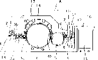
Fig. 1 has the diagrammatic side view by the carding machine of device of the present invention,
Fig. 2 presses the partial view of the device of Fig. 1,
The diagrammatic side view by of the present invention device of Fig. 3 on a clarifier,
The handing-over and the stretching of fibrous material between two cooperative rollers of Fig. 4,
Fig. 5 discreet knives disposes with respect to the angle and distance of the licker-in of a band saw tooth card clothing,
Fig. 6 another kind of form of implementation of the present invention.
The specific embodiment
Fig. 1 represents a carding machine, and for example the efficient carding machine DK903 of Tr ü tzschler has a feeding roller 1, curtain formula feed table 2, card clothing roller (licker-in) 3a, 3b, 3c, comber cylinder 4, doffer 5 (Abnehmer), angle stripper 6, removal of impurities grating roller (Quetschwalzen) 7,8, fine hair induction element 9, fine hair funnel 10, carry-over pinch rolls 11,12 and the revolving flats 13 that has the rod of cover 14 of slow circulation.The direction of rotation of carding machine roller is represented by the arrow of bending.The can coiler 16 that one tape tube 15 is arranged in the exit of carding machine is with the storage strip.Represent flow direction (fibrous material flow direction) with A.Be provided with a discreet knives 22 in the roll gap (wedge shape) between card clothing roller (licker-in) 3a and 3b, be provided with a discreet knives 27 in the roll gap between card clothing roller (licker-in) 3b and 3c.
The fibrous material for the treatment of combing flows to fiber feeding device with the form of lap by a device that does not specifically draw, and this device is made up of curtain formula feed table 2 and feeding roller 1.Lap is fixed between feeding roller 1 and the curtain formula feed table 2, and turns to nail roller 3a direction slowly to carry by 1 dextrorotation of feeding roller.The nail thorn 32 of card clothing roller (nail roller) 3a embeds in the lap of pushing ahead, and fiber is got loose from lap, and lap passes the nail thorn or pin 32 continues to carry.Here card clothing roller (nail roller) 3a is with the speed rotation more much higher than feeding roller 1, and with opposite being rotated counterclockwise of direction of rotation of feeding roller 1.The fiber of shredding is through a separating opening, and the separation blade in a discreet knives gets on except that foreign material there, by means of an aspirator they is exported.Then through a fixing combing element 18, card clothing roller (licker-in) 3b rotates fiber clockwise and with the peripheral speed higher than card clothing roller (licker-in) 3a before its arrives follow-up card clothing roller (licker-in) 3b that is equipped with saw-tooth clothing 34.Fiber is handed to card clothing roller (licker-in) 3c that is rotated counterclockwise by card clothing roller (licker-in) 3b of rotation.Card clothing roller (licker-in) 3c also is equipped with saw-tooth clothing 36, but sawtooth is done carefullyyer than card clothing roller (licker-in) 3b here.Fiber is handed to the comber cylinder 4 of carding machine by card clothing roller (licker-in) 3c.All card clothing rollers (licker-in or nail roller) 3a to 3c can be equipped with cladding element.
Between card clothing roller (licker-in) 3a and 3b, there are two roll gap wedge areas.Press that Fig. 2 assembles, just establish a cladding element 21 along the roll gap of direction of rotation 31 and 33 closures, extrudate for example, it makes the roll gap sealing.What disperse, just along establishing a discreet knives 22 in direction of rotation 31 and the 33 open roll gaps, it separates the direction of rotation 33 and card clothing 34 settings Face to face spaced apart of contrary card clothing roller (licker-in) 3b of blade 22a.Can adjust by a regulator 25 apart from a (see figure 5), for example adjust screw.The same cladding element 23 that has an openend that is provided with in the roll gap of dispersing, it covers the part of card clothing roller (licker-in) 3a.Cladding element 23 (with unillustrated method) can move with one heart with the shell surface of card clothing roller (licker-in) 3a.Also can leave card clothing roller (licker-in) 3a or rotate around a pivot to card clothing roller (licker-in) 3a.Discreet knives 22 and cladding element 23 set a common suction hood 24 that is used for waste material, dust, staple fibre or the like.
There are two roll gap wedge areas between card clothing roller (licker-in) 3b and the 3c in the corresponding way.Press that Fig. 2 assembles, just establish a cladding element 26 along the roll gap of direction of rotation 33 and 35 closures, extrudate for example, it seals roll gap.What disperse, just along being provided with a discreet knives 27 in direction of rotation 33 and the 35 open roll gaps, its direction of rotation 35 of separating contrary card clothing roller (licker-in) 3c of blade 27a is provided with Face to face with card clothing 36 a spaced apart.Can pass through regulator 30 apart from a, for example adjust the screw adjustment.The same cladding element 28 that is provided with the bending of a band openend 28a in the roll gap of dispersing, it covers the part of card clothing roller (licker-in) 3b.Cladding element 28 can (with unillustrated method) and the mobile with one heart revolution in other words of the shell surface of card clothing roller (licker-in) 3b.It is one common that discreet knives 27 and cladding element 28 set, and is used for the suction hood 29 of waste material, dust, staple fibre or the like.
Card clothing roller (licker-in) 3b sets three fixedly combing element 19a, 19b and 19c, and card clothing roller (licker-in) 3c sets two fixedly combing element 20a, 20b.Fixedly combing element is arranged on the back of each preposition discreet knives along the roller direction of rotation.
Press Fig. 3 card clothing roller 31,32,33 and 34 and be provided with in turn, its direction of rotation A, B, C and D represent.The one pneumatic aspirator 35 that is used for fibrous material (arrow F) is arranged at card clothing roller 34 ends.Card clothing roller 31 is identical with 34 diameter.The peripheral speed of each rearmounted roller is greater than the peripheral speed of each preposition roller.
Carry the fibrous material to be clean, particularly cotton of bulk fibre form for the purifier that is arranged in the closure casing.For example by one (unillustrated) charging hopper, conveyer belt or the like carries out for this.Lap is by means of two feeding rollers 36,37, flows to card clothing roller (nail roller) 31 (diameter 150 to 300mm, for example 250mm) under situation about clamping, and it can be rotated to support in the housing and (arrow A) rotation counterclockwise.A card clothing roller 32 is established in card clothing roller (nail roller) 31 back.Card clothing roller 32 covers saw-tooth clothing, and has about 150 to 300mm, for example the diameter of 250mm.Card clothing roller 31 peripheral speeds are about 10 to 21 meter per seconds, 15 meter per seconds for example, and the peripheral speed of card clothing roller 32 is about 15 to 25 meter per seconds, card clothing roller 33 has about 30 to 35 meter per seconds, the peripheral speed of 32 meter per seconds for example, the peripheral speed of card clothing roller 34 is about 40 to 50 meter per seconds, for example 46 meter per seconds.
Card clothing roller (nail roller) 31 sets a separating opening 38 that is used for discharging fiber impurity, and pollution level of its size and cotton adapts or can mate therewith.Separating opening 38 sets one and separates blade 39, for example blade.Be provided with another separating opening in card clothing roller 31 upper edge arrow A directions and separate blade with one.Represent fixedly combing element with 42 and 43.
Adjacent at two, be respectively equipped with a cladding element that fills up roll gap in the convergence roll gap between the cooperative roller, also be the cladding element 44 between card clothing roller 31 and 32, the cladding element 45 between the card clothing roller 32 and 33, and the cladding element between card clothing roller 33 and 34 46.Per two adjacent, dispersing between the cooperative roller is respectively equipped with the discreet knives that a band separates blade in the roll gap, also be the discreet knives 47 between card clothing roller 31 and 32, discreet knives 48 between the card clothing roller 32 and 33 and the discreet knives 49 between card clothing roller 33 and 34.
The card clothing roller 31 on discreet knives 47 opposites sets a cladding element 50, the card clothing roller 32 on discreet knives 48 opposites sets a cladding element 51, the card clothing roller 33 on discreet knives 49 opposites sets a cladding element 52, discreet knives 47 and cladding element 50 are connected on the common aspirator 53, discreet knives 48 and cladding element 51 are on aspirator 54, and discreet knives 49 and cladding element 52 are connected on the aspirator.Between the openend 50a of the separation blade 47a of discreet knives 47 and cladding element 50 a slit b is arranged, this slit-shaped becomes to separate mouth, and the waste material I that separates from fibrous material H passes this slit and siphons away.Slit b stretches into roll gap dearly.Between the narrowest position between slit b and card clothing roller 31 and 32, there is not member.Fibrous material H transfers on the card clothing roller 32 from card clothing roller 31 in this space.Corresponding judgement also is suitable for being arranged on the discreet knives 47,48,49 of back, cladding element 50,51,52, and suction hood 53,54,55, the roll gap of dispersing, the roll gap of convergence, the fibrous material handing-over, waste material separates and discharges or the like.
Operation principle is as follows: the lap of being made up of bulk fibre is by feeding roller 36,37 flow to card clothing roller (nail roller) 31 under clamped condition, it leads to the fibrous material comb and fibre bundle is carried on its nail thorn, other through out-of-date at card clothing roller 31 from separating opening, separate corresponding separating opening size staple fibre and thick impurity with curvature and with this first order because centrifugal force throws away corresponding to the peripheral speed of this roller from fibrous material, they are through arriving behind the separating opening in the impurity chamber in the housing.The fibrous material of preliminary clearning is sent from first card clothing roller 31 by the card clothing spine of card clothing roller 32 like this, at this moment its further shredding.From ribbon, throw away by centrifugal force through out-of-date other impurity from separating blade 47a next door at card clothing roller 32.
Rotate card clothing roller (licker-in) faster and in the zone of open size , stand one-off drawing when 3c gets on transferring to according to Fig. 4 fibrous material H, represent first open size with from slower card clothing roller (licker-in) 3d of rotation.This opening size be equivalent to basically fibrous material H from card clothing roller (licker-in) 3b dispersal point and the distance between the acceptance point that receives by card clothing roller (licker-in) 3c of fibrous material H.Fibrous material H is called the second open size Y from dispersal point and the distance between the cladding element 28 openend 28a on card clothing roller (licker-in) 3b.
Represent the impurity separated with I, as waste material or the like.
Set a discreet knives 56 in the roll gap of dispersing, for card clothing roller (licker-in) 3a by Fig. 6, set a cladding element 57 for card clothing roller (licker-in) 3b.
Claims (24)
1. be used for the carding machine of fibrous material or the device on the clarifier, have at least two card clothing rollers that are arranged on the input unit back, set the discreet knives that has affiliated separating opening that a reverse rotational direction is arranged, be used for impurity wherein at least one card clothing roller, for the drawing of fiber material, the peripheral speed of rearmounted card clothing roller is greater than the peripheral speed of the card clothing roller that is connected the front, each card clothing roller is connected mutually, rearmounted card clothing roller and the card clothing roller that is connected the front are separately as sending and the opening roller co-operation, it is characterized by: discreet knives (22,27,27a; 47; 48,49; 56) be arranged on two cooperative card clothing rollers (3a, 3b, 3c; 31,32,33,34) in the roll gap wedge area between.
2. by the device of claim 1, it is characterized by: at card clothing roller (3a, 3b, a 3c; 31,32,33,34) discreet knives of locating (22,27,27a; 47; 48,49; 56) with a cladding element (23,28; 50,51,52; 57) co-operation, cladding element to small part covers corresponding another card clothing roller (3a, 3b, 3c; 31,32,33,34).
3. by the device of claim 2, it is characterized by: cladding element (23,28; 50,51,52; 57) be crooked.
4. by the device of claim 2, it is characterized by: cladding element (23,28; 50,51,52; 57) can be parallel to roller surfaces moves.
5. by each device of claim 1 to 4, it is characterized by: discreet knives (22,27,27a; 47,48,49; 56) set a suction hood (24,29 that is used for waste material; 53,54,55; 58).
6. by each device of claim 1 to 4, it is characterized by: discreet knives (22,27,27a, 47,48,49,56) is with respect to card clothing roller (3a, 3b, 3c; 31,32,33,34) the tangential setting.
7. by each device of claim 1 to 4, it is characterized by: discreet knives (22,27,27a; 47,48,49; 56) with respect to card clothing roller (3a, 3b, 3c; 31,32,33,34) at angle (α) is provided with.
8. by each device of claim 1 to 4, it is characterized by: each rearmounted card clothing roller (3b, 3c; 32,33,34) direction of rotation (3
3, 3
5B, C is D) with the card clothing roller (3a, the 3b that respectively are connected the front; 31,32,33) direction of rotation (3
1, 3
3, A, B is C) opposite.
9. by each device of claim 1 to 4, it is characterized by: each rearmounted card clothing roller (3b, 3c; 32,33,34) direction of rotation (3
3, 3
5, B, C is D) with each preposition card clothing roller (3a, 3b; 31,32,33) each direction of rotation is identical.
10. by each device of claim 1 to 4, it is characterized by: discreet knives (22,27,27a; 47,48,49; 56) and card clothing roller (3a, 3b, 3c; 31,32,33,34) card clothing (3
2, 3
4, 3
660,61,62,63) there is a distance (a) between.
11. each the device by claim 1 to 4 is characterized by: each rearmounted card clothing roller (3b, 3c; 32,33,34) separation blade is equipped on two cooperative card clothing rollers.
12. each the device by claim 2 to 4 is characterized by: each preposition card clothing roller (3a, 3b; 31,32,33) cladding element (23,28; 50,51,52; 57) be equipped on two cooperative card clothing rollers.
13. by each device of claim 1 to 4, it is characterized in that: fibrous material (H) is at cooperative card clothing roller (3a, 3b, 3c; Turned to when shifting 31,32,33,34).
14. each the device by claim 2 to 4 is characterized by: waste material (I) from discreet knives (22,27,27a; 47,48,49; 56) and cladding element (23,28; 50,51,52; 57) pass between.
15. each the device by claim 1 to 4 is characterized by: discreet knives (22,27,27a; 47,48,49; 56) be arranged in the open roll gap of promptly dispersing.
16. each the device by claim 1 to 4 is characterized by: the open size () of the acceptance point of the dispersal point on the last card clothing roller of fibrous material from two cooperative card clothing rollers to one card clothing roller of back is adjustable.
17. each the device by claim 1 to 4 is characterized by: separate opening and be arranged in the roll gap.
18. the device by claim 5 is characterized by: suction hood (24,29; 53,54,55; 58) be equipped on roll gap.
19. each the device by claim 2 to 4 is characterized by: cladding element (23,28; 50,51,52; 57) be arranged in the roll gap.
20. each the device by claim 2 to 4 is characterized by: cladding element (23,28; 50,51,52; 57) openend (28a) and fibrous material are from card clothing roller (3a, 3b, 3c; 31,32,33,34) distance between the dispersal point on is adjustable.
21. by each device of claim 1 to 4, it is characterized by: device is arranged between per two card clothing rollers (31,32,33,34) of a multiple roll clarifier.
22. each the device by claim 1 to 4 is characterized by: device is arranged on per two card clothing rollers of carding machine, and (3a, 3b are between the licker-in 3c).
23. each the device by claim 1 to 4 is characterized by: card clothing roller (3a, 3b, 3c; 31,32,33,34) set fixedly combing element (18,19a, 19b, 20a, 20b; 42,43; 56a, 56b; 57a, 57b; 58a, 58b).
24. by the device of claim 16, it is characterized by: described open size can be adjusted according to fibre length and/or waste material amount.
Applications Claiming Priority (2)
| Application Number | Priority Date | Filing Date | Title |
|---|---|---|---|
| DE10048664.9 | 2000-09-30 | ||
| DE10048664A DE10048664A1 (en) | 2000-09-30 | 2000-09-30 | Device on a card, cleaner or the like for fiber material, especially cotton |
Publications (2)
| Publication Number | Publication Date |
|---|---|
| CN1344824A CN1344824A (en) | 2002-04-17 |
| CN1293244C true CN1293244C (en) | 2007-01-03 |
Family
ID=7658338
Family Applications (1)
| Application Number | Title | Priority Date | Filing Date |
|---|---|---|---|
| CNB01141216XA Expired - Fee Related CN1293244C (en) | 2000-09-30 | 2001-09-28 | Device for crading machine and treater for fibre material, especially cotton |
Country Status (8)
| Country | Link |
|---|---|
| US (1) | US6539586B2 (en) |
| JP (1) | JP2002155430A (en) |
| CN (1) | CN1293244C (en) |
| CH (1) | CH695779A5 (en) |
| DE (1) | DE10048664A1 (en) |
| FR (1) | FR2814759B1 (en) |
| GB (1) | GB2367306B (en) |
| IT (1) | ITMI20011956A1 (en) |
Families Citing this family (9)
| Publication number | Priority date | Publication date | Assignee | Title |
|---|---|---|---|---|
| DE50307306D1 (en) * | 2002-02-26 | 2007-07-05 | Rieter Ag Maschf | Method and device for cleaning the leaving zone on a carding machine |
| DE102010022479A1 (en) * | 2010-06-02 | 2011-12-08 | TRüTZSCHLER GMBH & CO. KG | Device on a card or card with a garnished drum and a neighboring garnished lickerin |
| TWI397498B (en) * | 2010-11-24 | 2013-06-01 | Avision Inc | Sheet de-curling mechanism and printing apparatus using the same |
| CN104593911B (en) * | 2015-03-02 | 2017-02-22 | 常熟市振泰无纺机械有限公司 | Card clothing cleaner of carding machine |
| EP3276055A1 (en) * | 2016-07-29 | 2018-01-31 | Tma-Sd, Llc. | Textile apparatus for opening and cleaning textile fiber material and method for opening and cleaning textile fiber material |
| CN107142564B (en) * | 2017-05-06 | 2020-06-02 | 青岛源泉机械有限公司 | Can separate cylinder and flat comb of impurity |
| CH714680A1 (en) * | 2018-02-26 | 2019-08-30 | Rieter Ag Maschf | Device for removing impurities in a card or a cleaner. |
| CN110344142A (en) * | 2019-07-23 | 2019-10-18 | 赣州安益宏科技有限公司 | A kind of highly-safe carding machine with clearing function |
| CN115369523B (en) * | 2022-09-15 | 2023-04-28 | 无锡城市职业技术学院 | Device and method for uniformly mixing color fibers |
Citations (2)
| Publication number | Priority date | Publication date | Assignee | Title |
|---|---|---|---|---|
| US4539728A (en) * | 1982-10-07 | 1985-09-10 | Portell Jose E | Cards |
| US5313688A (en) * | 1990-09-17 | 1994-05-24 | Trutzschler Gmbh & Co. Kg | Fiber waste separator including carriers, movable covers, and suction hood |
Family Cites Families (18)
| Publication number | Priority date | Publication date | Assignee | Title |
|---|---|---|---|---|
| US4126914A (en) * | 1976-06-22 | 1978-11-28 | Cotton, Incorporated | Process and apparatus for treating fibrous materials for subsequent processing |
| JPS59187628A (en) * | 1983-02-26 | 1984-10-24 | ツリユツラ−・ゲゼルシヤフト・ミツト・ベシユレンクテル・ハフツング・ウント・コンパニ−・コマンデイトゲゼルシヤフト | Dust collector for card |
| US4831691A (en) * | 1987-10-09 | 1989-05-23 | John D. Hollingsworth On Wheels, Inc. | Compact carding apparatus with sliver thread-up and method |
| DE3902204C2 (en) | 1989-01-26 | 2003-04-30 | Truetzschler Gmbh & Co Kg | Device on a card, cleaning machine or the like for cotton fibers, in which a support element is assigned to a roller |
| JPH0382948A (en) * | 1989-08-25 | 1991-04-08 | Shimadzu Corp | High sensitivity analyzing method of benzodiazepine compound |
| IT1231054B (en) * | 1989-09-27 | 1991-11-12 | Marzoli & C Spa | APPARATUS FOR CARDING OF TEXTILE MATERIALS. |
| DE4039773C2 (en) * | 1990-01-23 | 2003-06-26 | Truetzschler Gmbh & Co Kg | Cotton opening and cleaning machine - has equal size cylinders and trash extn. in stages |
| DE4018311C2 (en) * | 1990-06-08 | 1999-05-20 | Truetzschler Gmbh & Co Kg | Device for cleaning and opening textile fiber material, in particular cotton, with a rotating pin or needle roller arranged downstream of a feed device |
| JP3082969B2 (en) * | 1990-09-17 | 2000-09-04 | ツリュツラー ゲゼルシャフト ミット ベシュレンクテル ハフツング ウント コンパニー コマンディトゲゼルシャフト | Equipment installed on cards for cotton fibers, clearer machines, etc. |
| US5862573A (en) * | 1990-09-17 | 1999-01-26 | Trutzschler GmbH & Co, KG | Carding machine having a fiber introducing apparatus |
| DE4200394B4 (en) * | 1991-03-19 | 2004-12-02 | Trützschler GmbH & Co KG | Device for cleaning and opening flake fiber material z. B. cotton, synthetic fiber u. like. |
| US5546635A (en) * | 1991-03-28 | 1996-08-20 | Trutzschler Gmbh & Co. Kg | Apparatus for cleaning and opening fiber tufts |
| DE4110297A1 (en) * | 1991-03-28 | 1992-10-01 | Truetzschler & Co | DEVICE FOR CLEANING AND OPENING FIBER GOODS THAT ARE IN FLAKE SHAPE, e.g. COTTON, SYNTHETIC FIBER GOODS AND THE LIKE. |
| DE4224939A1 (en) * | 1992-07-28 | 1994-02-03 | Hollingsworth Gmbh | teasel |
| US5737806A (en) * | 1994-05-26 | 1998-04-14 | Trutzschler Gmbh & Co. Kg | Apparatus for treating fiber and producing a fiber lap therefrom |
| DE4418377A1 (en) * | 1994-05-26 | 1995-11-30 | Truetzschler Gmbh & Co Kg | Device on a card, especially for cotton, man-made fibers and. the like |
| DE4439564B4 (en) * | 1994-11-05 | 2005-05-04 | Trützschler GmbH & Co KG | Apparatus for cleaning and opening fibrous material in flake form, e.g. As cotton, synthetic fiber material u. like. |
| DE4441254A1 (en) * | 1994-11-19 | 1996-05-23 | Truetzschler Gmbh & Co Kg | Device for opening and cleaning flake fiber material, for. B. cotton, synthetic fiber u. the like |
-
2000
- 2000-09-30 DE DE10048664A patent/DE10048664A1/en not_active Withdrawn
-
2001
- 2001-09-17 CH CH01707/01A patent/CH695779A5/en not_active IP Right Cessation
- 2001-09-19 IT IT2001MI001956A patent/ITMI20011956A1/en unknown
- 2001-09-20 JP JP2001286322A patent/JP2002155430A/en active Pending
- 2001-09-27 FR FR0112416A patent/FR2814759B1/en not_active Expired - Fee Related
- 2001-09-28 US US09/964,430 patent/US6539586B2/en not_active Expired - Fee Related
- 2001-09-28 CN CNB01141216XA patent/CN1293244C/en not_active Expired - Fee Related
- 2001-09-28 GB GB0123425A patent/GB2367306B/en not_active Expired - Fee Related
Patent Citations (2)
| Publication number | Priority date | Publication date | Assignee | Title |
|---|---|---|---|---|
| US4539728A (en) * | 1982-10-07 | 1985-09-10 | Portell Jose E | Cards |
| US5313688A (en) * | 1990-09-17 | 1994-05-24 | Trutzschler Gmbh & Co. Kg | Fiber waste separator including carriers, movable covers, and suction hood |
Also Published As
| Publication number | Publication date |
|---|---|
| CH695779A5 (en) | 2006-08-31 |
| GB2367306A (en) | 2002-04-03 |
| FR2814759A1 (en) | 2002-04-05 |
| CN1344824A (en) | 2002-04-17 |
| ITMI20011956A0 (en) | 2001-09-19 |
| GB0123425D0 (en) | 2001-11-21 |
| ITMI20011956A1 (en) | 2003-03-19 |
| DE10048664A1 (en) | 2002-05-08 |
| US20020038494A1 (en) | 2002-04-04 |
| GB2367306B (en) | 2004-04-07 |
| US6539586B2 (en) | 2003-04-01 |
| JP2002155430A (en) | 2002-05-31 |
| FR2814759B1 (en) | 2005-06-03 |
Similar Documents
| Publication | Publication Date | Title |
|---|---|---|
| US4827574A (en) | Device for removing short fibers | |
| CN100453717C (en) | Apparatus having at least one separating knife in cotton carding machine, dust-colecting machnie or the like | |
| CN101012578B (en) | Apparatus for cleaning fibre material on a flat machine, a roller card | |
| CN1293244C (en) | Device for crading machine and treater for fibre material, especially cotton | |
| US5146652A (en) | Apparatus for opening and cleaning fiber material | |
| JP3126760B2 (en) | Equipment installed on cards for cotton fibers, clearer machines, etc. | |
| CN103510189A (en) | Device on spinning room preparation machine for opening and cleaning fibre material | |
| EP0423856A1 (en) | Carding apparatus for textile materials | |
| CN1327054C (en) | Device on carding machine, multiple working elements on roller, e.g.card can, on carding machine | |
| GB2222607A (en) | Apparatus for opening and cleaning fibre material | |
| US4129924A (en) | Apparatus for separating card strips during carding of fibrous materials | |
| GB2271126A (en) | Apparatus and method for processing fibre material | |
| CN1370862A (en) | Mechanism for carding machine and its cover with at least one hole | |
| GB2221701A (en) | Improvements in and relating to textile machines | |
| US6477742B2 (en) | Device for separating waste from fiber material while processed in a carding machine | |
| US5546635A (en) | Apparatus for cleaning and opening fiber tufts | |
| CN1304658C (en) | Device mounted on wool card or cotton card for levelling fibre web or ribbon | |
| EP0952244B1 (en) | Unit for opening and separation of the impurities, for machines for opening or carding of flock textile material | |
| JPH05195328A (en) | Apparatus for cleaning and opening fiber material which exists in shape of fibrous lump, for example, cotton, synthetic fiber material, etc. | |
| JPH07324228A (en) | Fixed flat card | |
| GB2376244A (en) | Arrangement at a textile fibre-processing machine for the removal of waste | |
| US6584651B2 (en) | Device for increasing the specific weight of fiber material in a carding machine | |
| EP0019455A1 (en) | Carding engine and method of carding textile fibres | |
| EP1378593A1 (en) | Carding machine and carding method | |
| US5771541A (en) | Apparatus for cleaning fibers |
Legal Events
| Date | Code | Title | Description |
|---|---|---|---|
| C06 | Publication | ||
| PB01 | Publication | ||
| C10 | Entry into substantive examination | ||
| SE01 | Entry into force of request for substantive examination | ||
| C14 | Grant of patent or utility model | ||
| GR01 | Patent grant | ||
| C17 | Cessation of patent right | ||
| CF01 | Termination of patent right due to non-payment of annual fee |
Granted publication date: 20070103 Termination date: 20110928 |