CN1286662A - Gear box - Google Patents
Gear box Download PDFInfo
- Publication number
- CN1286662A CN1286662A CN98812624A CN98812624A CN1286662A CN 1286662 A CN1286662 A CN 1286662A CN 98812624 A CN98812624 A CN 98812624A CN 98812624 A CN98812624 A CN 98812624A CN 1286662 A CN1286662 A CN 1286662A
- Authority
- CN
- China
- Prior art keywords
- gear
- clutch
- gear box
- moment
- change speed
- Prior art date
- Legal status (The legal status is an assumption and is not a legal conclusion. Google has not performed a legal analysis and makes no representation as to the accuracy of the status listed.)
- Granted
Links
- 230000008859 change Effects 0.000 claims description 288
- 230000005540 biological transmission Effects 0.000 claims description 148
- 238000012546 transfer Methods 0.000 claims description 98
- 229920000136 polysorbate Polymers 0.000 claims description 36
- 244000144983 clutch Species 0.000 claims description 14
- 239000007858 starting material Substances 0.000 claims description 11
- 230000008878 coupling Effects 0.000 abstract 8
- 238000010168 coupling process Methods 0.000 abstract 8
- 238000005859 coupling reaction Methods 0.000 abstract 8
- 238000000034 method Methods 0.000 description 134
- 230000001360 synchronised effect Effects 0.000 description 69
- 230000008569 process Effects 0.000 description 52
- 230000001133 acceleration Effects 0.000 description 41
- 230000000694 effects Effects 0.000 description 40
- 230000002441 reversible effect Effects 0.000 description 40
- 238000002485 combustion reaction Methods 0.000 description 38
- 230000002349 favourable effect Effects 0.000 description 26
- 238000010586 diagram Methods 0.000 description 20
- 230000009471 action Effects 0.000 description 14
- 230000007246 mechanism Effects 0.000 description 12
- 230000007935 neutral effect Effects 0.000 description 12
- 230000009467 reduction Effects 0.000 description 10
- 241000446313 Lamella Species 0.000 description 9
- 238000006073 displacement reaction Methods 0.000 description 9
- 230000006870 function Effects 0.000 description 9
- 238000013016 damping Methods 0.000 description 7
- 230000000630 rising effect Effects 0.000 description 7
- 230000000712 assembly Effects 0.000 description 6
- 238000000429 assembly Methods 0.000 description 6
- 230000008901 benefit Effects 0.000 description 6
- 238000006243 chemical reaction Methods 0.000 description 6
- 239000012530 fluid Substances 0.000 description 6
- 230000033001 locomotion Effects 0.000 description 6
- 238000003825 pressing Methods 0.000 description 6
- 230000015572 biosynthetic process Effects 0.000 description 5
- 230000001141 propulsive effect Effects 0.000 description 5
- 238000007789 sealing Methods 0.000 description 5
- 230000001419 dependent effect Effects 0.000 description 4
- 238000013461 design Methods 0.000 description 4
- 230000004907 flux Effects 0.000 description 4
- 230000001105 regulatory effect Effects 0.000 description 4
- 230000008093 supporting effect Effects 0.000 description 4
- 230000002035 prolonged effect Effects 0.000 description 3
- 238000003860 storage Methods 0.000 description 3
- 230000007704 transition Effects 0.000 description 3
- IAZDPXIOMUYVGZ-UHFFFAOYSA-N Dimethylsulphoxide Chemical compound CS(C)=O IAZDPXIOMUYVGZ-UHFFFAOYSA-N 0.000 description 2
- 230000000295 complement effect Effects 0.000 description 2
- 230000003750 conditioning effect Effects 0.000 description 2
- 230000001276 controlling effect Effects 0.000 description 2
- 238000011161 development Methods 0.000 description 2
- 230000001976 improved effect Effects 0.000 description 2
- 238000007689 inspection Methods 0.000 description 2
- 238000005259 measurement Methods 0.000 description 2
- 230000001095 motoneuron effect Effects 0.000 description 2
- 238000012856 packing Methods 0.000 description 2
- 230000001052 transient effect Effects 0.000 description 2
- 101000945093 Homo sapiens Ribosomal protein S6 kinase alpha-4 Proteins 0.000 description 1
- 101000945096 Homo sapiens Ribosomal protein S6 kinase alpha-5 Proteins 0.000 description 1
- 101150034459 Parpbp gene Proteins 0.000 description 1
- 235000014676 Phragmites communis Nutrition 0.000 description 1
- 102100033644 Ribosomal protein S6 kinase alpha-4 Human genes 0.000 description 1
- 102100033645 Ribosomal protein S6 kinase alpha-5 Human genes 0.000 description 1
- 239000003082 abrasive agent Substances 0.000 description 1
- 210000004712 air sac Anatomy 0.000 description 1
- 238000013459 approach Methods 0.000 description 1
- 239000000872 buffer Substances 0.000 description 1
- 230000003139 buffering effect Effects 0.000 description 1
- 239000003054 catalyst Substances 0.000 description 1
- 230000009194 climbing Effects 0.000 description 1
- 230000006835 compression Effects 0.000 description 1
- 238000007906 compression Methods 0.000 description 1
- 239000007799 cork Substances 0.000 description 1
- 230000009193 crawling Effects 0.000 description 1
- 230000007423 decrease Effects 0.000 description 1
- 238000001514 detection method Methods 0.000 description 1
- 238000009826 distribution Methods 0.000 description 1
- 238000001035 drying Methods 0.000 description 1
- 230000009977 dual effect Effects 0.000 description 1
- 238000004146 energy storage Methods 0.000 description 1
- 239000000446 fuel Substances 0.000 description 1
- ZZUFCTLCJUWOSV-UHFFFAOYSA-N furosemide Chemical compound C1=C(Cl)C(S(=O)(=O)N)=CC(C(O)=O)=C1NCC1=CC=CO1 ZZUFCTLCJUWOSV-UHFFFAOYSA-N 0.000 description 1
- 231100001261 hazardous Toxicity 0.000 description 1
- 230000002706 hydrostatic effect Effects 0.000 description 1
- 230000008676 import Effects 0.000 description 1
- 238000002347 injection Methods 0.000 description 1
- 239000007924 injection Substances 0.000 description 1
- 238000009434 installation Methods 0.000 description 1
- 238000012432 intermediate storage Methods 0.000 description 1
- 238000004519 manufacturing process Methods 0.000 description 1
- 239000000463 material Substances 0.000 description 1
- 230000000116 mitigating effect Effects 0.000 description 1
- 230000004048 modification Effects 0.000 description 1
- 238000012986 modification Methods 0.000 description 1
- 230000035772 mutation Effects 0.000 description 1
- 238000005457 optimization Methods 0.000 description 1
- 230000002093 peripheral effect Effects 0.000 description 1
- 230000001737 promoting effect Effects 0.000 description 1
- 230000001172 regenerating effect Effects 0.000 description 1
- 230000004044 response Effects 0.000 description 1
- 238000005096 rolling process Methods 0.000 description 1
- 230000035807 sensation Effects 0.000 description 1
- 230000035939 shock Effects 0.000 description 1
- 238000004904 shortening Methods 0.000 description 1
- 230000009466 transformation Effects 0.000 description 1
Images


Classifications
-
- F—MECHANICAL ENGINEERING; LIGHTING; HEATING; WEAPONS; BLASTING
- F16—ENGINEERING ELEMENTS AND UNITS; GENERAL MEASURES FOR PRODUCING AND MAINTAINING EFFECTIVE FUNCTIONING OF MACHINES OR INSTALLATIONS; THERMAL INSULATION IN GENERAL
- F16H—GEARING
- F16H3/00—Toothed gearings for conveying rotary motion with variable gear ratio or for reversing rotary motion
- F16H3/02—Toothed gearings for conveying rotary motion with variable gear ratio or for reversing rotary motion without gears having orbital motion
- F16H3/16—Toothed gearings for conveying rotary motion with variable gear ratio or for reversing rotary motion without gears having orbital motion essentially with both gears that can be put out of gear and continuously-meshing gears that can be disengaged from their shafts
-
- B—PERFORMING OPERATIONS; TRANSPORTING
- B60—VEHICLES IN GENERAL
- B60W—CONJOINT CONTROL OF VEHICLE SUB-UNITS OF DIFFERENT TYPE OR DIFFERENT FUNCTION; CONTROL SYSTEMS SPECIALLY ADAPTED FOR HYBRID VEHICLES; ROAD VEHICLE DRIVE CONTROL SYSTEMS FOR PURPOSES NOT RELATED TO THE CONTROL OF A PARTICULAR SUB-UNIT
- B60W10/00—Conjoint control of vehicle sub-units of different type or different function
- B60W10/02—Conjoint control of vehicle sub-units of different type or different function including control of driveline clutches
-
- F—MECHANICAL ENGINEERING; LIGHTING; HEATING; WEAPONS; BLASTING
- F16—ENGINEERING ELEMENTS AND UNITS; GENERAL MEASURES FOR PRODUCING AND MAINTAINING EFFECTIVE FUNCTIONING OF MACHINES OR INSTALLATIONS; THERMAL INSULATION IN GENERAL
- F16H—GEARING
- F16H61/00—Control functions within control units of change-speed- or reversing-gearings for conveying rotary motion ; Control of exclusively fluid gearing, friction gearing, gearings with endless flexible members or other particular types of gearing
- F16H61/04—Smoothing ratio shift
- F16H61/0403—Synchronisation before shifting
-
- B—PERFORMING OPERATIONS; TRANSPORTING
- B60—VEHICLES IN GENERAL
- B60L—PROPULSION OF ELECTRICALLY-PROPELLED VEHICLES; SUPPLYING ELECTRIC POWER FOR AUXILIARY EQUIPMENT OF ELECTRICALLY-PROPELLED VEHICLES; ELECTRODYNAMIC BRAKE SYSTEMS FOR VEHICLES IN GENERAL; MAGNETIC SUSPENSION OR LEVITATION FOR VEHICLES; MONITORING OPERATING VARIABLES OF ELECTRICALLY-PROPELLED VEHICLES; ELECTRIC SAFETY DEVICES FOR ELECTRICALLY-PROPELLED VEHICLES
- B60L15/00—Methods, circuits, or devices for controlling the traction-motor speed of electrically-propelled vehicles
- B60L15/20—Methods, circuits, or devices for controlling the traction-motor speed of electrically-propelled vehicles for control of the vehicle or its driving motor to achieve a desired performance, e.g. speed, torque, programmed variation of speed
-
- B—PERFORMING OPERATIONS; TRANSPORTING
- B60—VEHICLES IN GENERAL
- B60L—PROPULSION OF ELECTRICALLY-PROPELLED VEHICLES; SUPPLYING ELECTRIC POWER FOR AUXILIARY EQUIPMENT OF ELECTRICALLY-PROPELLED VEHICLES; ELECTRODYNAMIC BRAKE SYSTEMS FOR VEHICLES IN GENERAL; MAGNETIC SUSPENSION OR LEVITATION FOR VEHICLES; MONITORING OPERATING VARIABLES OF ELECTRICALLY-PROPELLED VEHICLES; ELECTRIC SAFETY DEVICES FOR ELECTRICALLY-PROPELLED VEHICLES
- B60L50/00—Electric propulsion with power supplied within the vehicle
- B60L50/10—Electric propulsion with power supplied within the vehicle using propulsion power supplied by engine-driven generators, e.g. generators driven by combustion engines
- B60L50/16—Electric propulsion with power supplied within the vehicle using propulsion power supplied by engine-driven generators, e.g. generators driven by combustion engines with provision for separate direct mechanical propulsion
-
- B—PERFORMING OPERATIONS; TRANSPORTING
- B60—VEHICLES IN GENERAL
- B60W—CONJOINT CONTROL OF VEHICLE SUB-UNITS OF DIFFERENT TYPE OR DIFFERENT FUNCTION; CONTROL SYSTEMS SPECIALLY ADAPTED FOR HYBRID VEHICLES; ROAD VEHICLE DRIVE CONTROL SYSTEMS FOR PURPOSES NOT RELATED TO THE CONTROL OF A PARTICULAR SUB-UNIT
- B60W10/00—Conjoint control of vehicle sub-units of different type or different function
- B60W10/10—Conjoint control of vehicle sub-units of different type or different function including control of change-speed gearings
- B60W10/11—Stepped gearings
-
- B—PERFORMING OPERATIONS; TRANSPORTING
- B60—VEHICLES IN GENERAL
- B60W—CONJOINT CONTROL OF VEHICLE SUB-UNITS OF DIFFERENT TYPE OR DIFFERENT FUNCTION; CONTROL SYSTEMS SPECIALLY ADAPTED FOR HYBRID VEHICLES; ROAD VEHICLE DRIVE CONTROL SYSTEMS FOR PURPOSES NOT RELATED TO THE CONTROL OF A PARTICULAR SUB-UNIT
- B60W30/00—Purposes of road vehicle drive control systems not related to the control of a particular sub-unit, e.g. of systems using conjoint control of vehicle sub-units
- B60W30/18—Propelling the vehicle
- B60W30/1819—Propulsion control with control means using analogue circuits, relays or mechanical links
-
- F—MECHANICAL ENGINEERING; LIGHTING; HEATING; WEAPONS; BLASTING
- F16—ENGINEERING ELEMENTS AND UNITS; GENERAL MEASURES FOR PRODUCING AND MAINTAINING EFFECTIVE FUNCTIONING OF MACHINES OR INSTALLATIONS; THERMAL INSULATION IN GENERAL
- F16H—GEARING
- F16H3/00—Toothed gearings for conveying rotary motion with variable gear ratio or for reversing rotary motion
- F16H3/02—Toothed gearings for conveying rotary motion with variable gear ratio or for reversing rotary motion without gears having orbital motion
- F16H3/08—Toothed gearings for conveying rotary motion with variable gear ratio or for reversing rotary motion without gears having orbital motion exclusively or essentially with continuously meshing gears, that can be disengaged from their shafts
- F16H3/087—Toothed gearings for conveying rotary motion with variable gear ratio or for reversing rotary motion without gears having orbital motion exclusively or essentially with continuously meshing gears, that can be disengaged from their shafts characterised by the disposition of the gears
-
- F—MECHANICAL ENGINEERING; LIGHTING; HEATING; WEAPONS; BLASTING
- F16—ENGINEERING ELEMENTS AND UNITS; GENERAL MEASURES FOR PRODUCING AND MAINTAINING EFFECTIVE FUNCTIONING OF MACHINES OR INSTALLATIONS; THERMAL INSULATION IN GENERAL
- F16H—GEARING
- F16H57/00—General details of gearing
- F16H57/02—Gearboxes; Mounting gearing therein
- F16H57/023—Mounting or installation of gears or shafts in the gearboxes, e.g. methods or means for assembly
-
- F—MECHANICAL ENGINEERING; LIGHTING; HEATING; WEAPONS; BLASTING
- F16—ENGINEERING ELEMENTS AND UNITS; GENERAL MEASURES FOR PRODUCING AND MAINTAINING EFFECTIVE FUNCTIONING OF MACHINES OR INSTALLATIONS; THERMAL INSULATION IN GENERAL
- F16H—GEARING
- F16H57/00—General details of gearing
- F16H57/02—Gearboxes; Mounting gearing therein
- F16H57/033—Series gearboxes, e.g. gearboxes based on the same design being available in different sizes or gearboxes using a combination of several standardised units
-
- B—PERFORMING OPERATIONS; TRANSPORTING
- B60—VEHICLES IN GENERAL
- B60L—PROPULSION OF ELECTRICALLY-PROPELLED VEHICLES; SUPPLYING ELECTRIC POWER FOR AUXILIARY EQUIPMENT OF ELECTRICALLY-PROPELLED VEHICLES; ELECTRODYNAMIC BRAKE SYSTEMS FOR VEHICLES IN GENERAL; MAGNETIC SUSPENSION OR LEVITATION FOR VEHICLES; MONITORING OPERATING VARIABLES OF ELECTRICALLY-PROPELLED VEHICLES; ELECTRIC SAFETY DEVICES FOR ELECTRICALLY-PROPELLED VEHICLES
- B60L2240/00—Control parameters of input or output; Target parameters
- B60L2240/40—Drive Train control parameters
- B60L2240/42—Drive Train control parameters related to electric machines
- B60L2240/421—Speed
-
- B—PERFORMING OPERATIONS; TRANSPORTING
- B60—VEHICLES IN GENERAL
- B60L—PROPULSION OF ELECTRICALLY-PROPELLED VEHICLES; SUPPLYING ELECTRIC POWER FOR AUXILIARY EQUIPMENT OF ELECTRICALLY-PROPELLED VEHICLES; ELECTRODYNAMIC BRAKE SYSTEMS FOR VEHICLES IN GENERAL; MAGNETIC SUSPENSION OR LEVITATION FOR VEHICLES; MONITORING OPERATING VARIABLES OF ELECTRICALLY-PROPELLED VEHICLES; ELECTRIC SAFETY DEVICES FOR ELECTRICALLY-PROPELLED VEHICLES
- B60L2240/00—Control parameters of input or output; Target parameters
- B60L2240/40—Drive Train control parameters
- B60L2240/42—Drive Train control parameters related to electric machines
- B60L2240/423—Torque
-
- B—PERFORMING OPERATIONS; TRANSPORTING
- B60—VEHICLES IN GENERAL
- B60L—PROPULSION OF ELECTRICALLY-PROPELLED VEHICLES; SUPPLYING ELECTRIC POWER FOR AUXILIARY EQUIPMENT OF ELECTRICALLY-PROPELLED VEHICLES; ELECTRODYNAMIC BRAKE SYSTEMS FOR VEHICLES IN GENERAL; MAGNETIC SUSPENSION OR LEVITATION FOR VEHICLES; MONITORING OPERATING VARIABLES OF ELECTRICALLY-PROPELLED VEHICLES; ELECTRIC SAFETY DEVICES FOR ELECTRICALLY-PROPELLED VEHICLES
- B60L2240/00—Control parameters of input or output; Target parameters
- B60L2240/40—Drive Train control parameters
- B60L2240/44—Drive Train control parameters related to combustion engines
- B60L2240/441—Speed
-
- B—PERFORMING OPERATIONS; TRANSPORTING
- B60—VEHICLES IN GENERAL
- B60L—PROPULSION OF ELECTRICALLY-PROPELLED VEHICLES; SUPPLYING ELECTRIC POWER FOR AUXILIARY EQUIPMENT OF ELECTRICALLY-PROPELLED VEHICLES; ELECTRODYNAMIC BRAKE SYSTEMS FOR VEHICLES IN GENERAL; MAGNETIC SUSPENSION OR LEVITATION FOR VEHICLES; MONITORING OPERATING VARIABLES OF ELECTRICALLY-PROPELLED VEHICLES; ELECTRIC SAFETY DEVICES FOR ELECTRICALLY-PROPELLED VEHICLES
- B60L2240/00—Control parameters of input or output; Target parameters
- B60L2240/40—Drive Train control parameters
- B60L2240/46—Drive Train control parameters related to wheels
- B60L2240/461—Speed
-
- B—PERFORMING OPERATIONS; TRANSPORTING
- B60—VEHICLES IN GENERAL
- B60L—PROPULSION OF ELECTRICALLY-PROPELLED VEHICLES; SUPPLYING ELECTRIC POWER FOR AUXILIARY EQUIPMENT OF ELECTRICALLY-PROPELLED VEHICLES; ELECTRODYNAMIC BRAKE SYSTEMS FOR VEHICLES IN GENERAL; MAGNETIC SUSPENSION OR LEVITATION FOR VEHICLES; MONITORING OPERATING VARIABLES OF ELECTRICALLY-PROPELLED VEHICLES; ELECTRIC SAFETY DEVICES FOR ELECTRICALLY-PROPELLED VEHICLES
- B60L2240/00—Control parameters of input or output; Target parameters
- B60L2240/40—Drive Train control parameters
- B60L2240/50—Drive Train control parameters related to clutches
- B60L2240/507—Operating parameters
-
- B—PERFORMING OPERATIONS; TRANSPORTING
- B60—VEHICLES IN GENERAL
- B60L—PROPULSION OF ELECTRICALLY-PROPELLED VEHICLES; SUPPLYING ELECTRIC POWER FOR AUXILIARY EQUIPMENT OF ELECTRICALLY-PROPELLED VEHICLES; ELECTRODYNAMIC BRAKE SYSTEMS FOR VEHICLES IN GENERAL; MAGNETIC SUSPENSION OR LEVITATION FOR VEHICLES; MONITORING OPERATING VARIABLES OF ELECTRICALLY-PROPELLED VEHICLES; ELECTRIC SAFETY DEVICES FOR ELECTRICALLY-PROPELLED VEHICLES
- B60L2250/00—Driver interactions
- B60L2250/10—Driver interactions by alarm
-
- B—PERFORMING OPERATIONS; TRANSPORTING
- B60—VEHICLES IN GENERAL
- B60L—PROPULSION OF ELECTRICALLY-PROPELLED VEHICLES; SUPPLYING ELECTRIC POWER FOR AUXILIARY EQUIPMENT OF ELECTRICALLY-PROPELLED VEHICLES; ELECTRODYNAMIC BRAKE SYSTEMS FOR VEHICLES IN GENERAL; MAGNETIC SUSPENSION OR LEVITATION FOR VEHICLES; MONITORING OPERATING VARIABLES OF ELECTRICALLY-PROPELLED VEHICLES; ELECTRIC SAFETY DEVICES FOR ELECTRICALLY-PROPELLED VEHICLES
- B60L2270/00—Problem solutions or means not otherwise provided for
- B60L2270/10—Emission reduction
- B60L2270/14—Emission reduction of noise
- B60L2270/145—Structure borne vibrations
-
- B—PERFORMING OPERATIONS; TRANSPORTING
- B60—VEHICLES IN GENERAL
- B60W—CONJOINT CONTROL OF VEHICLE SUB-UNITS OF DIFFERENT TYPE OR DIFFERENT FUNCTION; CONTROL SYSTEMS SPECIALLY ADAPTED FOR HYBRID VEHICLES; ROAD VEHICLE DRIVE CONTROL SYSTEMS FOR PURPOSES NOT RELATED TO THE CONTROL OF A PARTICULAR SUB-UNIT
- B60W2510/00—Input parameters relating to a particular sub-units
- B60W2510/06—Combustion engines, Gas turbines
- B60W2510/0638—Engine speed
-
- B—PERFORMING OPERATIONS; TRANSPORTING
- B60—VEHICLES IN GENERAL
- B60W—CONJOINT CONTROL OF VEHICLE SUB-UNITS OF DIFFERENT TYPE OR DIFFERENT FUNCTION; CONTROL SYSTEMS SPECIALLY ADAPTED FOR HYBRID VEHICLES; ROAD VEHICLE DRIVE CONTROL SYSTEMS FOR PURPOSES NOT RELATED TO THE CONTROL OF A PARTICULAR SUB-UNIT
- B60W2510/00—Input parameters relating to a particular sub-units
- B60W2510/06—Combustion engines, Gas turbines
- B60W2510/0657—Engine torque
-
- B—PERFORMING OPERATIONS; TRANSPORTING
- B60—VEHICLES IN GENERAL
- B60W—CONJOINT CONTROL OF VEHICLE SUB-UNITS OF DIFFERENT TYPE OR DIFFERENT FUNCTION; CONTROL SYSTEMS SPECIALLY ADAPTED FOR HYBRID VEHICLES; ROAD VEHICLE DRIVE CONTROL SYSTEMS FOR PURPOSES NOT RELATED TO THE CONTROL OF A PARTICULAR SUB-UNIT
- B60W2710/00—Output or target parameters relating to a particular sub-units
- B60W2710/02—Clutches
- B60W2710/021—Clutch engagement state
-
- B—PERFORMING OPERATIONS; TRANSPORTING
- B60—VEHICLES IN GENERAL
- B60W—CONJOINT CONTROL OF VEHICLE SUB-UNITS OF DIFFERENT TYPE OR DIFFERENT FUNCTION; CONTROL SYSTEMS SPECIALLY ADAPTED FOR HYBRID VEHICLES; ROAD VEHICLE DRIVE CONTROL SYSTEMS FOR PURPOSES NOT RELATED TO THE CONTROL OF A PARTICULAR SUB-UNIT
- B60W2710/00—Output or target parameters relating to a particular sub-units
- B60W2710/10—Change speed gearings
- B60W2710/1005—Transmission ratio engaged
-
- F—MECHANICAL ENGINEERING; LIGHTING; HEATING; WEAPONS; BLASTING
- F16—ENGINEERING ELEMENTS AND UNITS; GENERAL MEASURES FOR PRODUCING AND MAINTAINING EFFECTIVE FUNCTIONING OF MACHINES OR INSTALLATIONS; THERMAL INSULATION IN GENERAL
- F16H—GEARING
- F16H3/00—Toothed gearings for conveying rotary motion with variable gear ratio or for reversing rotary motion
- F16H3/006—Toothed gearings for conveying rotary motion with variable gear ratio or for reversing rotary motion power being selectively transmitted by either one of the parallel flow paths
- F16H2003/007—Toothed gearings for conveying rotary motion with variable gear ratio or for reversing rotary motion power being selectively transmitted by either one of the parallel flow paths with two flow paths, one being directly connected to the input, the other being connected to the input though a clutch
-
- F—MECHANICAL ENGINEERING; LIGHTING; HEATING; WEAPONS; BLASTING
- F16—ENGINEERING ELEMENTS AND UNITS; GENERAL MEASURES FOR PRODUCING AND MAINTAINING EFFECTIVE FUNCTIONING OF MACHINES OR INSTALLATIONS; THERMAL INSULATION IN GENERAL
- F16H—GEARING
- F16H57/00—General details of gearing
- F16H57/02—Gearboxes; Mounting gearing therein
- F16H2057/02039—Gearboxes for particular applications
- F16H2057/02043—Gearboxes for particular applications for vehicle transmissions
- F16H2057/02052—Axle units; Transfer casings for four wheel drive
-
- F—MECHANICAL ENGINEERING; LIGHTING; HEATING; WEAPONS; BLASTING
- F16—ENGINEERING ELEMENTS AND UNITS; GENERAL MEASURES FOR PRODUCING AND MAINTAINING EFFECTIVE FUNCTIONING OF MACHINES OR INSTALLATIONS; THERMAL INSULATION IN GENERAL
- F16H—GEARING
- F16H61/00—Control functions within control units of change-speed- or reversing-gearings for conveying rotary motion ; Control of exclusively fluid gearing, friction gearing, gearings with endless flexible members or other particular types of gearing
- F16H61/04—Smoothing ratio shift
- F16H61/0403—Synchronisation before shifting
- F16H2061/0422—Synchronisation before shifting by an electric machine, e.g. by accelerating or braking the input shaft
-
- F—MECHANICAL ENGINEERING; LIGHTING; HEATING; WEAPONS; BLASTING
- F16—ENGINEERING ELEMENTS AND UNITS; GENERAL MEASURES FOR PRODUCING AND MAINTAINING EFFECTIVE FUNCTIONING OF MACHINES OR INSTALLATIONS; THERMAL INSULATION IN GENERAL
- F16H—GEARING
- F16H61/00—Control functions within control units of change-speed- or reversing-gearings for conveying rotary motion ; Control of exclusively fluid gearing, friction gearing, gearings with endless flexible members or other particular types of gearing
- F16H61/04—Smoothing ratio shift
- F16H2061/0425—Bridging torque interruption
- F16H2061/0429—Bridging torque interruption by torque supply with a clutch in parallel torque path
-
- F—MECHANICAL ENGINEERING; LIGHTING; HEATING; WEAPONS; BLASTING
- F16—ENGINEERING ELEMENTS AND UNITS; GENERAL MEASURES FOR PRODUCING AND MAINTAINING EFFECTIVE FUNCTIONING OF MACHINES OR INSTALLATIONS; THERMAL INSULATION IN GENERAL
- F16H—GEARING
- F16H2200/00—Transmissions for multiple ratios
- F16H2200/003—Transmissions for multiple ratios characterised by the number of forward speeds
- F16H2200/0047—Transmissions for multiple ratios characterised by the number of forward speeds the gear ratios comprising five forward speeds
-
- F—MECHANICAL ENGINEERING; LIGHTING; HEATING; WEAPONS; BLASTING
- F16—ENGINEERING ELEMENTS AND UNITS; GENERAL MEASURES FOR PRODUCING AND MAINTAINING EFFECTIVE FUNCTIONING OF MACHINES OR INSTALLATIONS; THERMAL INSULATION IN GENERAL
- F16H—GEARING
- F16H2200/00—Transmissions for multiple ratios
- F16H2200/003—Transmissions for multiple ratios characterised by the number of forward speeds
- F16H2200/0052—Transmissions for multiple ratios characterised by the number of forward speeds the gear ratios comprising six forward speeds
-
- F—MECHANICAL ENGINEERING; LIGHTING; HEATING; WEAPONS; BLASTING
- F16—ENGINEERING ELEMENTS AND UNITS; GENERAL MEASURES FOR PRODUCING AND MAINTAINING EFFECTIVE FUNCTIONING OF MACHINES OR INSTALLATIONS; THERMAL INSULATION IN GENERAL
- F16H—GEARING
- F16H2306/00—Shifting
- F16H2306/40—Shifting activities
- F16H2306/48—Synchronising of new gear
-
- F—MECHANICAL ENGINEERING; LIGHTING; HEATING; WEAPONS; BLASTING
- F16—ENGINEERING ELEMENTS AND UNITS; GENERAL MEASURES FOR PRODUCING AND MAINTAINING EFFECTIVE FUNCTIONING OF MACHINES OR INSTALLATIONS; THERMAL INSULATION IN GENERAL
- F16H—GEARING
- F16H3/00—Toothed gearings for conveying rotary motion with variable gear ratio or for reversing rotary motion
- F16H3/006—Toothed gearings for conveying rotary motion with variable gear ratio or for reversing rotary motion power being selectively transmitted by either one of the parallel flow paths
-
- F—MECHANICAL ENGINEERING; LIGHTING; HEATING; WEAPONS; BLASTING
- F16—ENGINEERING ELEMENTS AND UNITS; GENERAL MEASURES FOR PRODUCING AND MAINTAINING EFFECTIVE FUNCTIONING OF MACHINES OR INSTALLATIONS; THERMAL INSULATION IN GENERAL
- F16H—GEARING
- F16H3/00—Toothed gearings for conveying rotary motion with variable gear ratio or for reversing rotary motion
- F16H3/02—Toothed gearings for conveying rotary motion with variable gear ratio or for reversing rotary motion without gears having orbital motion
- F16H3/08—Toothed gearings for conveying rotary motion with variable gear ratio or for reversing rotary motion without gears having orbital motion exclusively or essentially with continuously meshing gears, that can be disengaged from their shafts
- F16H3/087—Toothed gearings for conveying rotary motion with variable gear ratio or for reversing rotary motion without gears having orbital motion exclusively or essentially with continuously meshing gears, that can be disengaged from their shafts characterised by the disposition of the gears
- F16H3/089—Toothed gearings for conveying rotary motion with variable gear ratio or for reversing rotary motion without gears having orbital motion exclusively or essentially with continuously meshing gears, that can be disengaged from their shafts characterised by the disposition of the gears all of the meshing gears being supported by a pair of parallel shafts, one being the input shaft and the other the output shaft, there being no countershaft involved
-
- F—MECHANICAL ENGINEERING; LIGHTING; HEATING; WEAPONS; BLASTING
- F16—ENGINEERING ELEMENTS AND UNITS; GENERAL MEASURES FOR PRODUCING AND MAINTAINING EFFECTIVE FUNCTIONING OF MACHINES OR INSTALLATIONS; THERMAL INSULATION IN GENERAL
- F16H—GEARING
- F16H3/00—Toothed gearings for conveying rotary motion with variable gear ratio or for reversing rotary motion
- F16H3/02—Toothed gearings for conveying rotary motion with variable gear ratio or for reversing rotary motion without gears having orbital motion
- F16H3/08—Toothed gearings for conveying rotary motion with variable gear ratio or for reversing rotary motion without gears having orbital motion exclusively or essentially with continuously meshing gears, that can be disengaged from their shafts
- F16H3/087—Toothed gearings for conveying rotary motion with variable gear ratio or for reversing rotary motion without gears having orbital motion exclusively or essentially with continuously meshing gears, that can be disengaged from their shafts characterised by the disposition of the gears
- F16H3/091—Toothed gearings for conveying rotary motion with variable gear ratio or for reversing rotary motion without gears having orbital motion exclusively or essentially with continuously meshing gears, that can be disengaged from their shafts characterised by the disposition of the gears including a single countershaft
- F16H3/0915—Toothed gearings for conveying rotary motion with variable gear ratio or for reversing rotary motion without gears having orbital motion exclusively or essentially with continuously meshing gears, that can be disengaged from their shafts characterised by the disposition of the gears including a single countershaft with coaxial input and output shafts
-
- F—MECHANICAL ENGINEERING; LIGHTING; HEATING; WEAPONS; BLASTING
- F16—ENGINEERING ELEMENTS AND UNITS; GENERAL MEASURES FOR PRODUCING AND MAINTAINING EFFECTIVE FUNCTIONING OF MACHINES OR INSTALLATIONS; THERMAL INSULATION IN GENERAL
- F16H—GEARING
- F16H3/00—Toothed gearings for conveying rotary motion with variable gear ratio or for reversing rotary motion
- F16H3/02—Toothed gearings for conveying rotary motion with variable gear ratio or for reversing rotary motion without gears having orbital motion
- F16H3/08—Toothed gearings for conveying rotary motion with variable gear ratio or for reversing rotary motion without gears having orbital motion exclusively or essentially with continuously meshing gears, that can be disengaged from their shafts
- F16H3/12—Toothed gearings for conveying rotary motion with variable gear ratio or for reversing rotary motion without gears having orbital motion exclusively or essentially with continuously meshing gears, that can be disengaged from their shafts with means for synchronisation not incorporated in the clutches
- F16H3/126—Toothed gearings for conveying rotary motion with variable gear ratio or for reversing rotary motion without gears having orbital motion exclusively or essentially with continuously meshing gears, that can be disengaged from their shafts with means for synchronisation not incorporated in the clutches using an electric drive
-
- F—MECHANICAL ENGINEERING; LIGHTING; HEATING; WEAPONS; BLASTING
- F16—ENGINEERING ELEMENTS AND UNITS; GENERAL MEASURES FOR PRODUCING AND MAINTAINING EFFECTIVE FUNCTIONING OF MACHINES OR INSTALLATIONS; THERMAL INSULATION IN GENERAL
- F16H—GEARING
- F16H63/00—Control outputs from the control unit to change-speed- or reversing-gearings for conveying rotary motion or to other devices than the final output mechanism
- F16H63/40—Control outputs from the control unit to change-speed- or reversing-gearings for conveying rotary motion or to other devices than the final output mechanism comprising signals other than signals for actuating the final output mechanisms
- F16H63/46—Signals to a clutch outside the gearbox
-
- Y—GENERAL TAGGING OF NEW TECHNOLOGICAL DEVELOPMENTS; GENERAL TAGGING OF CROSS-SECTIONAL TECHNOLOGIES SPANNING OVER SEVERAL SECTIONS OF THE IPC; TECHNICAL SUBJECTS COVERED BY FORMER USPC CROSS-REFERENCE ART COLLECTIONS [XRACs] AND DIGESTS
- Y02—TECHNOLOGIES OR APPLICATIONS FOR MITIGATION OR ADAPTATION AGAINST CLIMATE CHANGE
- Y02T—CLIMATE CHANGE MITIGATION TECHNOLOGIES RELATED TO TRANSPORTATION
- Y02T10/00—Road transport of goods or passengers
- Y02T10/60—Other road transportation technologies with climate change mitigation effect
- Y02T10/64—Electric machine technologies in electromobility
-
- Y—GENERAL TAGGING OF NEW TECHNOLOGICAL DEVELOPMENTS; GENERAL TAGGING OF CROSS-SECTIONAL TECHNOLOGIES SPANNING OVER SEVERAL SECTIONS OF THE IPC; TECHNICAL SUBJECTS COVERED BY FORMER USPC CROSS-REFERENCE ART COLLECTIONS [XRACs] AND DIGESTS
- Y02—TECHNOLOGIES OR APPLICATIONS FOR MITIGATION OR ADAPTATION AGAINST CLIMATE CHANGE
- Y02T—CLIMATE CHANGE MITIGATION TECHNOLOGIES RELATED TO TRANSPORTATION
- Y02T10/00—Road transport of goods or passengers
- Y02T10/60—Other road transportation technologies with climate change mitigation effect
- Y02T10/70—Energy storage systems for electromobility, e.g. batteries
-
- Y—GENERAL TAGGING OF NEW TECHNOLOGICAL DEVELOPMENTS; GENERAL TAGGING OF CROSS-SECTIONAL TECHNOLOGIES SPANNING OVER SEVERAL SECTIONS OF THE IPC; TECHNICAL SUBJECTS COVERED BY FORMER USPC CROSS-REFERENCE ART COLLECTIONS [XRACs] AND DIGESTS
- Y02—TECHNOLOGIES OR APPLICATIONS FOR MITIGATION OR ADAPTATION AGAINST CLIMATE CHANGE
- Y02T—CLIMATE CHANGE MITIGATION TECHNOLOGIES RELATED TO TRANSPORTATION
- Y02T10/00—Road transport of goods or passengers
- Y02T10/60—Other road transportation technologies with climate change mitigation effect
- Y02T10/7072—Electromobility specific charging systems or methods for batteries, ultracapacitors, supercapacitors or double-layer capacitors
-
- Y—GENERAL TAGGING OF NEW TECHNOLOGICAL DEVELOPMENTS; GENERAL TAGGING OF CROSS-SECTIONAL TECHNOLOGIES SPANNING OVER SEVERAL SECTIONS OF THE IPC; TECHNICAL SUBJECTS COVERED BY FORMER USPC CROSS-REFERENCE ART COLLECTIONS [XRACs] AND DIGESTS
- Y02—TECHNOLOGIES OR APPLICATIONS FOR MITIGATION OR ADAPTATION AGAINST CLIMATE CHANGE
- Y02T—CLIMATE CHANGE MITIGATION TECHNOLOGIES RELATED TO TRANSPORTATION
- Y02T10/00—Road transport of goods or passengers
- Y02T10/60—Other road transportation technologies with climate change mitigation effect
- Y02T10/72—Electric energy management in electromobility
-
- Y—GENERAL TAGGING OF NEW TECHNOLOGICAL DEVELOPMENTS; GENERAL TAGGING OF CROSS-SECTIONAL TECHNOLOGIES SPANNING OVER SEVERAL SECTIONS OF THE IPC; TECHNICAL SUBJECTS COVERED BY FORMER USPC CROSS-REFERENCE ART COLLECTIONS [XRACs] AND DIGESTS
- Y10—TECHNICAL SUBJECTS COVERED BY FORMER USPC
- Y10T—TECHNICAL SUBJECTS COVERED BY FORMER US CLASSIFICATION
- Y10T74/00—Machine element or mechanism
- Y10T74/19—Gearing
- Y10T74/19219—Interchangeably locked
- Y10T74/19251—Control mechanism
-
- Y—GENERAL TAGGING OF NEW TECHNOLOGICAL DEVELOPMENTS; GENERAL TAGGING OF CROSS-SECTIONAL TECHNOLOGIES SPANNING OVER SEVERAL SECTIONS OF THE IPC; TECHNICAL SUBJECTS COVERED BY FORMER USPC CROSS-REFERENCE ART COLLECTIONS [XRACs] AND DIGESTS
- Y10—TECHNICAL SUBJECTS COVERED BY FORMER USPC
- Y10T—TECHNICAL SUBJECTS COVERED BY FORMER US CLASSIFICATION
- Y10T74/00—Machine element or mechanism
- Y10T74/19—Gearing
- Y10T74/19219—Interchangeably locked
- Y10T74/19293—Longitudinally slidable
- Y10T74/19298—Multiple spur gears
- Y10T74/19307—Selective
- Y10T74/19312—Direct clutch and drive
-
- Y—GENERAL TAGGING OF NEW TECHNOLOGICAL DEVELOPMENTS; GENERAL TAGGING OF CROSS-SECTIONAL TECHNOLOGIES SPANNING OVER SEVERAL SECTIONS OF THE IPC; TECHNICAL SUBJECTS COVERED BY FORMER USPC CROSS-REFERENCE ART COLLECTIONS [XRACs] AND DIGESTS
- Y10—TECHNICAL SUBJECTS COVERED BY FORMER USPC
- Y10T—TECHNICAL SUBJECTS COVERED BY FORMER US CLASSIFICATION
- Y10T74/00—Machine element or mechanism
- Y10T74/19—Gearing
- Y10T74/19219—Interchangeably locked
- Y10T74/19293—Longitudinally slidable
- Y10T74/19298—Multiple spur gears
- Y10T74/19316—Progressive
- Y10T74/19321—Direct clutch and drive
Landscapes
- Engineering & Computer Science (AREA)
- Mechanical Engineering (AREA)
- General Engineering & Computer Science (AREA)
- Transportation (AREA)
- Chemical & Material Sciences (AREA)
- Combustion & Propulsion (AREA)
- Power Engineering (AREA)
- Automation & Control Theory (AREA)
- Structure Of Transmissions (AREA)
- Arrangement Of Transmissions (AREA)
- Control Of Transmission Device (AREA)
Abstract
A variable speed gear box (1) comprising at least two shafts, i.e. an input shaft and an output shaft (5), in addition to a plurality of gear pairs, loose wheels (30, 31, 32, 33, 34, 35) which can be rotationally fixed to a first shaft (5) by means of couplings (40, 41, 50), shift wheels (20, 21, 22, 23, 24, 25) that are rotationally fixed with a shaft (4), and a shiftable starting coupling (3) arranged on the input side. At least one of the couplings (40, 51, 50) is embodied as a powershift coupling (50). The starting coupling (3) and the powershift coupling (50) can be actuated by at least one actuating unit. For practical reasons, the powershift coupling can be engaged when the starting coupling is at least partially engaged.
Description
The present invention relates to a kind of change speed gear box such as speed-changing gear box, it has at least two axles as a main shaft and a driven shaft and a presumable tween drive shaft, and described change speed gear box has many gear mesh and can not have by adapter and primary shaft and relatively rotates bonded assembly gear such as idle gear and a start clutch of connecting that is arranged on input side.
In automobile, such change speed gear box is well-known.Its shortcoming is that it can not carry out power shfit, in other words, in the gearshift procedure that changes the change speed gear box transmitting ratio, always exists tractive force and interrupts.
Task of the present invention provides the change speed gear box of the above-mentioned type, and it can carry out power shfit and it can be made of simply used member simultaneously.
According to the present invention, so finish above-mentioned task, but promptly one of them adapter is designed to have the power-transfer clutch such as the power shift clutch of higher transfer torque, and start clutch and power shift clutch can be handled by a steering unit at least.
In addition, when start clutch is engaged at least in part, then can engage power shift clutch, this is suitable.
Same suitable is when engaging start clutch, can engage power shift clutch so.Being bonded on this is meant and can have been improved by the moment of torsion of clutch transmits.
Advantageously, at least one idle gear can link to each other with an axle by first adapter and/or a power shift clutch.
When two idle gears can link to each other with an axle by first adapter and/or a power shift clutch, this also was suitable.
Same suitable is that the idle gear of top-gear can link to each other with an axle by an adapter and/or a power shift clutch.
In another embodiment advantageously, the adapter that is used to connect at least one idle gear and an axle be one by form fit bonded assembly adapter.
If be used to connect the adapter of at least one idle gear and an axle is an adapter by frictional connection, then is favourable.
Further advantageously, the synchro that inserts in the middle of having one of the adapter that is used to connect at least one idle gear and an axle.
Power shift clutch is a frictional connection formula power-transfer clutch, and this also is suitable.When start clutch (Anfahrkupplung) was a frictional connection formula power-transfer clutch, this was suitable especially.
Advantageously, start clutch is positioned in the space region of a clutch case.
When at least one power shift clutch was positioned in the space region of a clutch case, this also was suitable.
When start clutch and at least one power shift clutch were a dry type clutch, this also was suitable.
In the time of in start clutch is positioned in transmission housing, this also is suitable.
When at least one power shift clutch was positioned in the transmission housing, this also was fit to.
When start clutch and/or at least one power shift clutch were a friction clutch, this also was favourable.
When start clutch was a turbine transformer that has or do not have a changer bridging clutch, this also was favourable.
In another embodiment, the manipulation executive item that is used to handle start clutch and at least one power shift clutch is a hydraulically controlled formula executive item with a pressure medium source of supply and at least one valve, described valve is being controlled respectively and is being carried to one on two power-transfer clutchs pressure medium of accepting cylinder, and this is suitable.
According to another imagination of the present invention, the manipulation executive item that is used to handle start clutch and at least one power shift clutch is one to have one equally and is connected the driving device behind an electrical motor or the electromagnet or the motor-driven executive item of drop-gear box, and this is suitable.
According to another imagination of the present invention, the manipulation executive item that is used to handle the speed change adapter is a hydraulically controlled formula executive item with a pressure medium source of supply and at least one valve, described valve is being controlled respectively and is being carried to one on the adapter pressure medium of accepting cylinder, and this is suitable.
According to another imagination of the present invention, the manipulation executive item that is used for operating contact maker is one to have one equally and is connected the driving device behind an electrical motor or the electromagnet or the motor-driven executive item of drop-gear box, and this is suitable.
According to another imagination of the present invention, change speed gear box has a motor, and it is used as the starter of automotive engine and/or by the electrical generator of kinetic energy and feedback generation electric energy thereof, this is suitable.
When coming drive motor by an escape wheel (Gangrad) of change speed gear box, perhaps during the described escape wheel of this motor-driven, this is favourable.
According to another imagination of the present invention, can drive described motor by a flywheel of automotive engine, the perhaps described flywheel of this motor-driven, this is favourable.
According to another imagination of the present invention, the described motor of main shaft drives that can be by change speed gear box, the perhaps described main shaft of this motor-driven, this is favourable.
When described motor has a stator and a rotor, wherein said stator and rotor be with the concentric setting of transmission main shaft the time, this is suitable.
When described motor has a stator and a rotor, wherein said stator is that a relative such axle is provided with rotor, and when promptly described axle was set up and locatees to such an extent that be roughly parallel to transmission main shaft, this was suitable.
When described motor has a stator and a rotor, wherein said stator and rotor are configured to concentric with transmission main shaft and described rotor and a flywheel or parts that link to each other with transmission main shaft not to be had when being connected with relatively rotating, and this also is suitable.
In conjunction with figure the present invention is described, wherein:
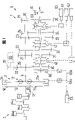
Fig. 1 is the scheme drawing of change speed gear box;
Fig. 2 is a diagram of curves;
Fig. 3 a is the schematic partial graph of change speed gear box;
Fig. 3 b is the schematic partial graph of change speed gear box;
Fig. 4 a is the schematic partial graph of change speed gear box;
Fig. 4 b is the schematic partial graph of change speed gear box;
Fig. 5 a is the scheme drawing of change speed gear box;
Fig. 5 b is the scheme drawing of change speed gear box;
Fig. 6 is the scheme drawing of change speed gear box;
Fig. 7 a is the scheme drawing of change speed gear box;
Fig. 7 b is the scheme drawing of change speed gear box;
Fig. 8 is the schematic section of change speed gear box;
Fig. 8 a is the schematic section of change speed gear box;
Fig. 9 is the schematic section of change speed gear box;
Fig. 9 a is the schematic section of change speed gear box;
Figure 10 shows a change speed gear box;
Figure 11 a is the partial graph of change speed gear box;
Figure 11 b is the partial graph of change speed gear box;
Figure 11 c is the partial graph of change speed gear box;
Figure 12 shows a change speed gear box;
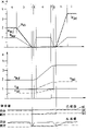
Figure 13 a-Figure 17 b is the diagram of curves according to time representation moment of torsion and rotating speed;
Figure 18 schematically shows a change speed gear box;
Figure 19-Figure 27 is a diagram of curves;
Figure 28 is a block scheme;
Figure 29 is a block scheme;
Figure 30-Figure 33 is a diagram of curves;
Figure 34 is a block scheme;
Figure 35 is a block scheme;
Figure 36-Figure 39 is a diagram of curves;
Figure 40 is a block scheme;
Figure 41-Figure 43 is a diagram of curves;
Figure 44 is a block scheme;
Figure 45-Figure 49 is a diagram of curves;
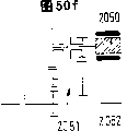
Figure 50 a-Figure 50 f shows general layout with section drawing;
Figure 51 is the automobile scheme drawing;
Figure 52-Figure 56 schematically shows other embodiment of change speed gear box of the present invention;
Figure 54 a-Figure 55 a is the diagram of curves that belongs to Figure 54,55 embodiment's and start clutch relevant with separating stroke or power shift clutch transmission of torque.
Fig. 1 schematically shows an automobile gearbox 1, and it is set at an actuating device 2 as driving engine or a combustion engine and a start clutch or 3 back as friction clutch that operate the clutch.Change speed gear box 1 has a main shaft 4, a tween drive shaft 5 and a presumable additional driven shaft 6, and in the embodiment in figure 1, tween drive shaft is equal to driven shaft.In another embodiment of the present invention, when being provided with an additional driven shaft 6 for main shaft 4 and tween drive shaft 5, this is favourable.Between driving engine 2 and change speed gear box 1, be provided with a flywheel 10, on flywheel, be provided with the friction clutch that has pressing plate and clutch cover back plate.Can replace equally fixedly that flywheel 10 ground are provided with a double mass flywheel, it has two the rotating mass portions that can support with relatively rotating with respect to each other, and they can overcome the reset force that for example is arranged on the force-storing device between the mass of flywheel portion and rotate.
Between clutch driven disc 3a and transmission main shaft 4, be provided with a torsional damping arrangement 11.It has at least two disk shaped part 11a, the 11b that can support with relatively rotating with respect to each other, and they can overcome as a reset force that is arranged on the force-storing device between the mass of flywheel portion rotates.On the clutch driven disc radially outer, friction covering is set preferably.
Axle is rotatably supported in the transmission housing as main shaft, driven shaft and presumable tween drive shaft by bearing and centering and being supported in the axial direction in case of necessity diametrically.But be not clearly shown that bearing.
Start clutch or operate the clutch 3 in an advantageous embodiments for example as the friction clutches of wet running be arranged in the transmission housing.In another advantageous embodiment, power-transfer clutch 3 is for example as dry type clutch ground as be arranged in the clutch case between driving engine 2 and change speed gear box 1.
Transmission gear 20-25 there is no with main shaft 4 axial restraints of change speed gear box 1 with relatively rotating and is connected.Transmission gear 20-25 and gear such as idle gear 30-35 engagement, described idle gear can be rotated on tween drive shaft 5 and can not have with axle 5 by adapter and be connected with relatively rotating.Between gear 25,35, be provided with a reverse idler gear 36.Therefore gear mesh 25,35,36 is a reverse gear R gear mesh.Gear mesh the 24, the 34th, first gear is right.Gear mesh the 23, the 33rd, second speed gear is right.Gear mesh the 22, the 32nd, 3rd gear is right.Gear mesh the 21, the 31st, fourth speed gear is right.Gear mesh 20,30 is five grades of gear mesh.In another advantageous embodiments, idle gear 30-35 also can be installed on the main shaft, and transmission gear can not only be provided with idle gear but also transmission gear is set on each axle in another embodiment on tween drive shaft.
Change speed gear box 1 has three standard packages as shown in the figure, and they are to be made of as the slide joint cover two gear mesh and the adapter that is placed in therebetween.One of them standard package A by gear mesh 20,30 and 21,31 and slide joint cover 40 constitute.The second standard package B by gear mesh 22,32 and 23,33 and slide joint cover 41 constitute.The 3rd standard package C by gear mesh 24,34 and 25,35,36 and slide joint cover 42 constitute.
As will seeing, the gear mesh of one grade and reverse gear R has constituted first standard package, and second gear and three-speed gear mesh have constituted second standard package, and the gear mesh of fourth gear and five grades has constituted the 3rd standard package.Also can be assembled into other standard packages of the present invention.
As handling the slide joint cover 40-42 that is used for change speed gear box 1 gear shift, between steering unit and slide joint cover, be provided with an attaching parts respectively by steering unit 60-62 as a bar, a fluid pressure section, a hauling rope, a bottom tie rod or a control lever shaft with moving axially.Steering unit can be that a motor operated driving mechanism, an electromagnetic drive mechanism and/or a pressure medium operated driver train are as a hydraulic efficiency gear.Relevant therewith ground is referring to DE4426260, DE19504847, DE19627980, DE19637001.The invention still further relates to these old patent applications, the content of these patent documentations belongs to the written disclosure content of present patent application.
In at least one attaching parts between steering unit and slide joint cover, a converter speed ratio i can be set.
The cooresponding change speed gear box of the present invention also for example is not subjected to generally restrictedly to be designed to the four-speed gear shift case (level Four D Drive) of a band reverse gear R or six grades of change speed gear boxs (six grades of D Drives) of a band reverse gear R.
For detect the change speed gear box output speed promptly axle 5 rotating speed and be provided with a tachogen 70.In order to detect the i.e. rotating speed of axle 4 of change speed gear box input speed, an additional tachogen 71 can also be set.For the detection of engine rotating speed, be provided with a tachogen 71.In order to control to starting to walk/operate the clutch and being used for changing the operation of the adapter of change speed gear box speed ratio, be provided with an electronic controller, it is furnished with memory device and computing machine and produces control signal with the control steering unit according to incoming signal.Can also use to stable drive ratio according to other measurement rotating speed and calculate a rotating speed.
Power-transfer clutch 80 links to each other as one among power shift clutch and the gear 30-34, and described power-transfer clutch makes this gear link to each other with axle 5 when it is engaged.Handling executive item 65 can handle as engage or cut-off clutch 80 by attaching parts 65b.Advantageously utilize with handle start clutch or operate the clutch 3 identical manipulation executive items or one independently executive item come operated clutch 80, handling executive item 65 can and disconnect described power-transfer clutch by attaching parts 65a joint.
When power-transfer clutch 80 was arranged on the axle head of the axle 5 adjacent with power-transfer clutch 3, this was favourable.In another advantageous embodiment,, also be suitable if power-transfer clutch 80 is arranged on the axle head opposite with power-transfer clutch 3 of axle 5.
Another favorable characteristics of change speed gear box is that the starter-generator 90 of motor such as starter, electrical generator or driving engine can come axle drive shaft 4 by gearbox gear such as gear 20-24.Can drive electrical generator such as automobile current generator equally.Particularly advantageous is that starter and electrical generator are combined into a comprehensive motor such as starter-electrical generator.Therefore, this motor can fire an engine.But in another operational mode, when driving change speed gear box, produce moment of torsion and therefore provide to drive and support to driving engine.At least temporarily or in short time be utilized separately for the driving automobile by suitable mode under the situation that this motor is low at moment of torsion or power output is little.In another embodiment or invention application examples, motor is used to automobile kinetic energy partly is transformed into electric energy and for example store in battery.This for example can realize in the promotion process at driving engine 2 when car descending and/or brake.The automobile that change speed gear box of the present invention is housed can advantageously reduce high-abrasive material loss and hazardous emission thus.Motor can also improve torque level when gear shift.
According to Fig. 1, motor 90 for example can and be configured to be parallel to transmission main shaft or the change speed gear box driven shaft by a gear drive.Between the driving gear 91 of a transmission gear such as gear 20 and motor 90, an intermediate gear 92 can be set.Also can come drive motor by belt or chain.For the speed change of motor and driving or for motor-driven, can adopt the driving device of the convertible or secured adjusted of an infinitely variable transmission system, branch gear stage.
In addition, motor can be positioned to the main shaft of change speed gear box concentric.
The present invention relates to power shfit or change speed gear box 1 that can power shfit.Power shfit so realizes or carries out, and the combustion engine 2 that promptly comprises main shaft 4 is subjected to the load of automotive driven chain by power shift clutch 80 and is braked.Therefore driving engine 2 kinetic energy partly are converted into automobile kinetic energy.
According to the present invention, be provided with a clutch control executive item at least, it is not only operated start clutch or operates the clutch 3, and steering maneuver gear shift sleeve 80.Advantageously, start clutch 3 is engaged when the steering maneuver gear shift sleeve at least in part.In another embodiment, to be engaged fully be suitable to start clutch.
Device of the present invention is simple and handle that executive item quantity is few to have superiority very much because of gearbox designs.
The advantage of this change speed gear box is: owing at least almost interruptedly do not carry out power shfit, so gear shift is very comfortable; Owing to may partly omit synchro, so scantling length is little; In light weight; High efficiency.
In device of the present invention, the driving engine kinetic energy during gear shift is not lost because of brake, but is applied pari passu as drive torque.Driving engine is subjected to the braking of driven chain.No longer producing tractive force thus interrupts.
This is very favourable when the traction upshift.This also is favourable when reverse gear R is changed in slip, because automobile kinetic energy is used to improve engine speed.
Idle gear is arranged on main shaft or the tween drive shaft, can be attached thereto by adapter or slide joint cover.Idle gear can link to each other with axle by operating contact maker.The slide joint cover is as making tween drive shaft 5 link to each other with idle gear by castellated adapter.The adapter by form fit of one grade or reverse gear R can be assembled into one with a friction clutch such as synchro, sees the baulk ring 50 that is used for a grade and reverse gear R.Adapter 40-42 can handle executive item by at least one and handle.
This system also comprises the electrical controller of a band microprocessor, it is used for electrically controlled gearbox and power-transfer clutch, measurement rotating speed, throttle electric control or engine load conditions, and this system comprises that also one is used for the electronic engine control system of combustion engine, artificial gear selecting operating parts lever, switch or similarity piece and gearshift display device that is contained in the automobile as being used for artificial and automatic gear selecting.
Can also be advantageously provided a motor that starter, electrical generator can be used as and may be used as automobile hydraulic brake (Retarter) and auxiliary drive.
For start-up course, in change speed gear box, hang low gear (a grade or second gear).When driving engine produces moment of torsion under the situation of pedal of stepping on the throttle, connect start clutch 3 so that make car acceleration by manipulation executive item 65.When start clutch adheres to, interrupt starting-up process.Now only moment of torsion is passed to tween drive shaft 5 by power-transfer clutch of connecting and the gear that hangs up.
Under any circumstance, gearshift procedure is all by the chaufeur gear selecting or pass through automatic guidance and realize.
When the traction upshift, clutch control executive item control power shift clutch 80 ground are connected it, and start clutch 3 keeps on-state.The moment of torsion that power shift clutch 80 is transmitted is high more, and adapter 40, the 41 or 42 suffered moments of torsion of then hanging (former) gear are more little.If the moment of torsion of the former shelves of hanging reduces to zero substantially, then disconnect the adapter of former shelves.By the transfer torque of frictional power gear shift sleeve 80, comprise that the rotating speed of the combustion engine of main shaft has reduced, this means that driving engine kinetic energy reduces.Therefore the moment of torsion of frictional power gear shift sleeve 80 is supported and the part kinetic energy of combustion engine 2 is provided to automobile on driven chain.Moment of torsion on the driven chain remains unchanged in synchronizing process, thus change speed gear box is carried out power shfit.
Reach synchronous speed if put the adapter 40,41 or 42 of new shelves, then connect this adapter by the operation executive item.Simultaneously, disconnect power shift clutch 80.New gear is hung up and is interrupted gearshift procedure.
When reaching synchronous speed, so control clutch moment and engine moment promptly only quicken combustion engine slightly and no longer quicken combustion engine basically under the situations of synchronous speed at once.Engage the adapter of new shelves now.If the joint operating contact maker then disconnects power shift clutch.
Power shift clutch 80 best one are installed on the idle gear of top-gear, but it also can be installed on the more low-grade idle gear.At this, the gear shift on more high-grade no longer can be carried out under the power shfit condition.For this reason, the gear shift on more low-grade (new shelves are not more than the shelves of drive gear shift sleeve) has very little tractive force and disturbs.
Improve engine moment.Simultaneously, power shift clutch bears moment of torsion, thereby can disconnect the operating contact maker of former shelves.Subsequently, can reduce the moment of torsion and the boost engine of power shift clutch.Before reaching synchronous speed at once, engage power shift clutch, retroengine also hangs up new shelves under synchronous speed.Now, disconnect power shift clutch, new shelves bear engine moment.
When gear down, must improve engine speed.For this reason, utilize self power to improve driving engine kinetic energy.Reduce engine torque controllably.If the moment of torsion of former shelves reduces to zero basically, the adapter 40,41 or 42 of then former shelves is disconnected.Now, improve engine torque, driving engine and main shaft are quickened.If driving engine has reached new shelves synchronous speed, then temporary transient returning fallen engine moment and engaged new shelves adapter 40,41 or 42.Now, regulate engine moment controllably according to the chaufeur hope again.
Can utilize the power shift clutch 80 on high speed gear more cosily to draw gear down, the part engine moment that wherein is conceived to be used to quicken combustion engine is strengthened on driven chain.Thus one, even prolonged synchronizing process, but torque is not reduced to zero.
If change speed gear box has second power shift clutch in deep low gear, then when promoting gear down, power-transfer clutch makes engine speed improve under the driven chain effect.Automobile is checked in synchronizing process subsequently, because automobile energy is shunted to driving engine.Therefore, under the power shfit condition, promote gear down equally subsequently.Replace power shift clutch, can on crawling gear or reverse gear R, utilize an efficient locking synchro such as double-cone synchronizer.
Fig. 2 shows a characteristic curve, and wherein showing as the function ground of the control run of handling executive item 65 can be by the moment of torsion M of start clutch 3 and power shift clutch 80 transmission
aAnd M
l
But the transfer torque of power- transfer clutch 3,80 is functions of control run.In the first area, but the transfer torque of power shift clutch is zero, but the transfer torque of start clutch raises.Engage and but transfer torque, engages power shift clutch 80, thereby formed the M of rising when irrelevant with control run when start clutch 3 is basic
1Eigenwert.
Fig. 3 a, 3b show embodiment with section drawing, wherein show the variation of the relative Fig. 1 embodiment of the present invention.The feature of unshowned Fig. 1 change speed gear box can be with reference to Fig. 1 in Fig. 3 a, 3b.
In Fig. 3 a, two manipulation executive items that are used to select the engage a gear position have been used.Handling executive item selects and operates desirable adapter 40,41,42 or slide joint cover and connect so that form between axle 5 and gear 30-35 in that the slide joint cover is moved.In addition, also be provided with a mechanism as a center control lever shaft perhaps multiaxis or bar between manipulation executive item 101,102, their allow to select the slide joint cover and allow slide joint to overlap axially to move by handling executive item.In use under the situation of heart control lever shaft, for example Zhou rotation is selected the slide joint cover and by drawing or pressing and realize axial operation axle.Can realize above-mentioned action according to opposite steering equally.In an embodiment with at least two joysticks, one of them handle executive item can carry out to the bar that will operate and and then the selection of the slide joint cover that will operate, and another is handled executive item and can draw or press selected bar.
In an embodiment with at least two control lever shafts, one of them is handled executive item and carries out the selection of slide joint cover by rotating the axle that will operate, and another handles executive item can realize moving axially of selected slide joint cover by rotating second.
In Fig. 3 b, used a manipulation executive item 105 that is used to select the engage a gear position.Handling executive item 105 selects and operates desirable adapter 40,41,42 or slide joint cover and connect so that form between axle 5 and gear 30-35 in that the slide joint cover is moved.In addition, also be provided with a mechanism 120 as an operation roller between manipulation executive item 105 and slide joint cover, its permission is selected slide joint to overlap by the manipulation executive item and is allowed the slide joint cover axial mobile.Under the situation of an operation roller, on the outer peripheral face of rotatable rollers, be provided with groove, the pin of slide joint cover embeds in the described groove, and the rotation of its central roll moves and gear shift in order the slide joint cover corresponding to trough.
Fig. 4 a shows an embodiment of change speed gear box of the present invention with section drawing, wherein fourth gear be installed in rotation on axle 204 with five grades idle gear 230,231 as on axle drive shaft or the main shaft and they can be connected with a nothing by slide joint cover or adapter 240 with relatively rotating, and described adapter is axially movable.Fourth gear and five grades transmission gear 220,221 are installed on driven shaft or the tween drive shaft and their do not have with relatively rotating and are connected with described axle.Idle gear 32-35 is installed on the axle 205, and corresponding transmission gear is installed on the axle 204.
One grade synchro is designed to combination tapered synchro 250 as double-cone synchronizer as the synchro between gear 34 and slide joint cover.
In this embodiment, motor 290 is as starter-electrical generator or starter (starter) or electrical generator (automobile current generator) driving three-speed transmission gear.It also can drive the transmission gear of another grade.
Fig. 4 b shows a change speed gear box of the present invention with section drawing, wherein by be installed in rotation on main shaft upper transfer gear 225, can axially movable intermediate gear 237 and one handle reverse gear R not having the tooth that relatively rotates on the bonded assembly slide joint cover 238 with driven shaft.In order to hang up reverse gear R, can move axially by a manipulation executive item 295 by axially movable intermediate gear 237, thereby between parts 225,237,238, have connection by form fit.
Fig. 5 a, 5b show the embodiment of change speed gear box of the present invention, wherein show and be connected on the diff 299,298 of driven shaft 205 back.In Fig. 5 a, be located in the axial end region of moment of torsion flux it and driving driving engine and start clutch position opposite behind the diff 299 of driven shaft or tween drive shaft 205.In Fig. 5 b, be located in the axial end region of moment of torsion flux behind the diff 298 of driven shaft or tween drive shaft 206, it is adjacent with start clutch with driving driving engine 2.
Fig. 6 shows the embodiment of a change speed gear box 300, and described change speed gear box mainly has the keystone configuration part of change speed gear box 1 shown in Figure 1, wherein in order to handle adapter or the slide joint cover that gear shift is used, has adopted two to handle executive item 360,361 shown in Fig. 3 a.They are by mechanism's 350 conversions or operating contact maker or slide joint cover 340,341,342, and described mechanism for example handles executive item by one of them and carries out the selection of slide joint cover and handle the operation that executive item carries out selected slide joint cover by another.
A power shift clutch 310 links to each other as the idle gear 330 of friction clutch with the 5th grade, and when engaging described power shift clutch, described power shift clutch makes idle gear 330 not have with axle 305 and links together with relatively rotating.In addition, second power shift clutch such as friction clutch link to each other with one grade idle gear 335, and described power shift clutch makes idle gear 335 not have with axle 305 when it is engaged and links together with relatively rotating.Therefore, as described above, power-transfer clutch 310 or power-transfer clutch 320 can be engaged so that can gear shift promptly can not have tractive force gear shift interruptedly.In order to operate the clutch 310,320, the manipulation executive item 362,363 that strap drive chain link 362a, 363a are provided is for use.Bar, quill shaft, band active cylinder and the hydraulic pressure bindiny mechanism that accepts cylinder are as drive link.The motor-driven executive item that has speed increaser or retarder can be used as executive item.Also advantageously, in another embodiment, adopted hydraulic operation formula executive item.
Fig. 7 a, 7b show the embodiment of change speed gear box 400 of the present invention, and wherein start clutch 403 is arranged in the change speed gear box clutch case but outside osed top transmission housing 401 own.In addition, clutch case is one and half open spaces, and its boundary member ground is arranged on by one that the clutch case outer cover limits on the change speed gear box, wherein clutch case be fixed on the automotive engine and therefore except inappreciable opening outer closure whole clutch case.In the embodiment of Fig. 7 a, it is in the space region 402 that the power shift clutch 480 that is used to connect idle gear 430 and axle 404 is arranged on clutch case.Realize that with being connected by a hollow shaft of idle gear described hollow shaft passes a casing wall opening, wherein by described hollow shaft, an axle 404 passes casing wall equally.Two power-transfer clutchs 403,480 are arranged in the clutch case chamber 402 and can advantageously be designed to friction clutch such as dry type clutch.Axle 404 and hollow shaft between power-transfer clutch 480 and the idle gear 430 advantageously are supported in outside the case shell by bearing part 450.
In the embodiment of Fig. 7 b, it is in the space region 400a that the power shift clutch 480 that is used to connect idle gear 430 and axle 404 is arranged on transmission housing.Realize with being connected of idle gear by a hollow shaft.Power-transfer clutch 403 is arranged in the clutch case chamber 402 and advantageously is designed to friction clutch such as dry type clutch.Power shift clutch 480 is arranged in the transmission housing and the friction clutch such as the lamella clutch of an advantageously wet running.Axle 404 advantageously is bearing in outside the case shell by bearing part 450.
In different embodiment, power shift clutch 80,480 can link to each other with the another one idle gear and the corresponding axle of another grade.It preferably links to each other with the idle gear of top-gear.
If power shift clutch 80 is arranged on the idle gear of top-gear or is coupled, then when top grade is changed in traction, can under power, change all shelves.If power shift clutch is arranged on the idle gear of low gear (as third gear or four-speed), then can not under power, change than its higher shelves.But there is such advantage, promptly seldom obtains the result that the power shfit tractive force interrupts.Power shift clutch 80 can resemble and be installed on main shaft 4 or the tween drive shaft 5 each idle gear.But it preferably is installed on the main shaft 4.In another advantageous embodiment, power shift clutch is installed on the tween drive shaft.
Power shift clutch 80 preferably spatially is positioned in the transmission housing close clutch case, perhaps even directly is placed on the bearing of main shaft.
Power shift clutch be positioned in the indoor of change speed gear box oiling or in clutch case.
The order of shelves or configuration can freely be selected, because change speed gear box is operated automatically, therefore do not need to resemble shelves preface required in manual-shift gearbox.This means that advantageously each two shelves that is engaged by a slide joint cover need not to be adjacent shelves, then are the sort of situations in manual-shift gearbox.
Change reverse gear R for the propelling under the power shfit condition and draw, can between slide joint cover and idle gear, use effectively in principle and change the efficient lock synchronizer of one grade of usefulness.In such system, lock synchronizer provides the part moment of torsion, and the moment of torsion of another part is provided combustion engine so that main shaft and combustion engine are synchronous.Yet tractive force so does not fully interrupt, but the part moment of torsion acts on the automobile driving chain by versatile spindle and driven gear.
Power shift clutch can advantageously be designed to following one of them power-transfer clutch:
-the power-transfer clutch that under wet condition, turns round;
-the power-transfer clutch that under drying condition, turns round;
-slip clutch;
-have a cone clutch of conical surface;
-one friction face;
-two friction faces;
-many friction faces (as lamella clutch).
The adapter or the slide joint cover that are used to connect idle gear and axle advantageously design in such a way:
-by form fit bonded assembly adapter, as castellated adapter;
The adapter of-frictional connection.
For the efficient that makes change speed gear box obtains optimization, when the adapter that is used for adapter shaft and idle gear or slide joint cover had extraneous additional-energy to consume ground to keep engagement state basically, this was very favorable.In order there not to be expenditure of energy ground to keep leaning on the adapter of frictional connection, can be advantageously provided storage power or energy storage component such as spring, they make friction face stressed mutually.Equally can use activity key type clutch (Ziehkeilgetriebe) or spring-loaded friction clutch.
The tooth of the form fit portion in leaning on form fit bonded assembly adapter can be designed to various, as the smooth-shaped of band fillet, and tuck pointing odontoid, Bo Lite inserted tooth or branch inserted tooth.
It may be favourable that one grade and/or reverse gear R are furnished with synchro.In another embodiment, when several at least shelves were furnished with a blocker synchronizer, this may be favourable.
Idle gear 30-35 and adapter 40-42 can arrange according to different modes in having the change speed gear box of tween drive shaft.Every grade idle gear can be installed on main shaft or the tween drive shaft.So in different embodiment, power shift clutch can be installed on one of them axle.
Change speed gear box is a design-calculated like this, and promptly for example it is designed to four-speed gear shift case, five grades of change speed gear boxs or six grades of change speed gear boxs or other many grades of speed-changing gear boxs.
An advantageous embodiment of change speed gear box of the present invention can be according to preceding-horizontal layout type setting.In automobile.Another embodiment can propose a kind of favourable preceding-vertical layout type, and wherein this layout also can be used to other favourable driver circuit structure.
In different embodiment, handle that executive item 60,61,62,65,101,105,105 and/or 363 advantageously is equipped with its output element to make the motor of rotator type output movement, the motor of doing the straight line output movement rotates the motor of executive item (as gear type pump, blade-type pump etc.), hydraulic linear executive item (as piston/cylinder assembly etc.), pneumatic rotation executive item (as blade-type pump etc.), pneumatic linear executive item (piston etc.), piezoelectricity executive item and hot mechanical executive item as having linear magnet, hydraulic pressure.
Between electrical motor and manipulation executive item, handle the mechanical drive that executive item can have driving device such as prior art: lever, key, cam drive, rotating shaft, worm screw, cylindrical wheel, planetary assemblies etc.; Or hydraulic actuator, pneumatic actuator (active cylinder/accept cylinder) or public pressure medium driving device.
For in check parts are turned to, according to embodiment, wherein a kind of transmission route form below can advantageously adopting.Can adopt adjustable or self-regulating transmission route, as mechanical route such as lever, stay cord, bar, slide plate, key, cam drive etc. or hydrostatic pressure route as the active cylinder that has or do not have the automatic deflation hole-accept cylinder, fluid power route or pneumatic route.
Be used to operate gear shift and select the manipulation executive item of follow-up shelves also can join together by intermediate transmission mechanism 110.To change many shelves the executive item right thereby can resemble.For example, corresponding to the auxiliary gear box of H-switch figure or operation roller, it arbitrarily changes four gears with an executive item.
Power-transfer clutch such as start clutch 3 or power shift clutch 80 can be designed to pressing of transmission or step type power-transfer clutch, and they remain under the force-storing device state of not operated by the spring prestress of a force-storing device pressurized.In addition, power-transfer clutch can be one and subtract power self-regulation power-transfer clutch, its automatic equalization the wearing and tearing of friction lining.In another embodiment, power-transfer clutch also can be the compression type power-transfer clutch, and it must be by executive item to small part or utilize component ground to handle, and this moment, it was switched on.
Torsional damping arrangement is advantageously located in the driven chain, and starting to walk/operating the clutch and driving engine between be provided with a spring damper 11.This bumper can be integrated into one with clutch plate or a double mass flywheel.
In addition, be equipped with following feature can also for automobile gearbox of the present invention:
-have have signal conditioning, the controller of the microprocessor of electronic circuit, control logic circuit, signal amplifier, data highway system etc.;
-display system such as alarm lamp, warning acoustical generator, gearshift display device etc.;
-operating parts such as shift knob, switch etc.;
-band is used to select automatic gear selecting, the manual program of the selection element of gear selecting, winter, motion, chaufeur identification etc.;
-electronics generator control unit on combustion engine has electronic fuel and carries control, as E gas (electrically operated, electronics etc.);
-be used for detecting engine rotating speed, vehicle wheel rotational speed, identification is opened in the identification of opening the door, car bonnet etc. detector;
-data between the engine controller of gearbox control and combustion engine exchange with control signal.
In an above-mentioned change speed gear box, the motor of can one packing into, as starter, starter, electrical generator resemble the automobile current generator or starter one electrical generator, hydraulic brake/auxiliary drive.In this case, it is a motor that satisfies following function advantageously, also may be used as the regenerating electric brake as cranking internal combustion engine, generation automobile wallboard electrical network with electric current, and wherein dump energy is supplied to actuating device again.Motor can be advantageously to Synchromous device of gearbox generation support effect and can equally advantageously to be used to make the braking of transmission main shaft rotating speed when the vehicle stationary be zero.So, in each embodiment, just can in reverse gear R or one grade, save baulk ring.In order to make moment of torsion reverse gear R steady when the gear shift, can advantageously clearly control motor so that in this stage, can utilize moment of torsion.
Motor can act on and start pusher side promptly on the flywheel as on the primary flywheel or secondary flywheel at double mass flywheel.In another embodiment, when motor acted on the transmission main shaft, this was favourable, and wherein motor not only can be to be provided with one heart, also can shift to install by axle.Motor can directly or by intermediate gearing drive combustion engine or main shaft.Intermediate gearing can have fixing or a change transmitting ratio.It can be changed between many fixing transmitting ratios back and forth, perhaps can the step-less adjustment transmitting ratio.Transmission ratios is as can being to realize by the control centnifugal force or by an executive item.
Rotatablely moving of motor can be delivered to engine shaft or transmission main shaft by following driving device:
-tooth (cylindrical wheel, finishing bevel gear cuter etc.)
-circulating drive (chain, cone belt are with etc. synchronously)
-hydraulic actuator (pump/electrical motor etc.)
-friction gear is as friction drive, endless drive or taper star change speed gear box.
In addition, starting process realizes by dual mode.Motor directly quickens combustion engine, and perhaps at first the independent drive motor also begins to drive combustion engine from high rotating speed subsequently, and this is because for example engaged friction clutch.After motor had formerly quickened transmission main shaft, such engine starting provided by start clutch.
Fig. 8 shows change speed gear box 500 of the present invention with section drawing.Here, start clutch 504 be placed in a nothing relatively rotate with flywheel 502 that driving engine driven shaft 501 links to each other on.In addition, power-transfer clutch is made of as the carrier ring and the disc spring 509 of in the axial direction disc spring 507 being pressed to pad or carrier ring clutch cover back plate 505, pressing plate 506 and disc spring 507 and lid side ring shape pad 508.In addition, disc spring is bearing on the annular arrangement pressing plate cam and radially inner being bearing on the ring-shaped article 508 radially outerly.Parts 509 can be designed to be made up of several sections, and wherein at least two parts are axially playing the effect of regulating the disc spring supporting area under the situation in relative rotation.
In addition, show clutch plate 520, it mainly is made of a clutch plate 521 and a respective disc 522, and they are made into the annular arrangement discoid component, and these members link together radially outerly spaced reciprocally.Flange 23 radial projection wherein are being provided with force-storing device 524 effectively between clutch plate and the respective disc and between clutch plate and flange between clutch plate and respective disc.Clutch plate and respective disc and clutch plate and flange are arranged to overcome force-storing device 524 reset force ground and rotate.Flange relatively rotates with wheel hub 525 nothings by a castellated shaft tooth radially innerly and is connected.Clutch plate 521 has an annulus radially outerly, and it constitutes by its elastomeric ferrodo 526 of conversion between the spring Duan Zaiqi by two.Pressing plate 506 wipe contacts of ferrodo and corresponding flywheel friction face and power-transfer clutch 504.
A clutch control lever 530 can be used to operate the clutch, and it can be supported rotationally around axle 531.Joystick 530 is received within a cross section radially innerly and becomes in the groove 531 of U-shaped, and described groove again can axially movable hollow cylinder seat 532 supportings by one.Groove can be circular.Hollow cylinder seat 532 outside race of release thrust bearing 535 at an one axle head district internal support, and wherein it encircles the axis bearing outer-ring radially outerly.The bearing inner ring axially mounting one and is used for operation board reed languid so that be switched on or switched off the block district of power-transfer clutch 504.In Fig. 8, joystick clockwise rotates, and power-transfer clutch is disconnected.By a guide groove 599 guide seat 532.In addition, be provided with an axial seat 598 and an axial seat thrust ring 597.
Wheel hub 525 is connected with transmission main shaft 503 nothings by the castellated shaft tooth with relatively rotating.
Change speed gear box 500 has a transmission housing 500a, and it also makes clutch case and change speed gear box inner chamber separate.The speed change tank wall has an opening, and transmission main shaft 503 passes described opening.Idle gear 560 is rotatably supported on the transmission main shaft 503 and centering by bearing 562.Simultaneously, idle gear 560 is bearing in outside the case by bearing 563, and wherein axially external member 560a puts bearing 563 radially outerly and puts bearing 562a radially innerly, and an external member 560b puts bearing 562b radially innerly.Sealing member 570 and bearing seal overlappingly and are arranged between two shell 500a and the parts 560a.Sealing member 571 is arranged between transmission main shaft 503 and the parts 560a hermetically.Sealing member also can be placed between shell and the guide groove.
Idle gear has a tooth 560c radially outerly in the opposed petiolarea of its tank wall, when slide joint cover 551 was axially shifted to idle gear, its form fit connected ground and embeds in the described tooth.This by being connected of form fit by between slide joint cover and the idle gear realized that transmission gear 561 and axle 503 are by leaning on being connected of form fit that idle gear 560 forms.Moving axially by bar such as gearbox forks 570 of slide joint cover 551 realize, described gearbox forks relies on form fit to overlap with slide joint in a groove that roughly becomes U-shaped to be connected radially outerly.In order to move axially,, wherein control executive item 571 by controller by bar control slide joint cover for this reason.
Executive item 580 is used to make bar 530 to rotate.
In order between contact pin 550 and idle gear, to form frictional connection, also be provided with power shift clutch 590.Power shift clutch 590 is designed to friction clutch or lamella clutch, thereby several at least clutch segments are bearing on the axially extended contact pin arm radially outerly and other several clutch segments are radially inner and nothing is bearing on the axially extended idle gear arm with relatively rotating, and wherein clutch segment is alternately arranged.For this reason, clutch segment has a ferrodo seat, ferrodo may be installed on this both sides, and one of them is radially outer and another has inner recess or otch or projection radially innerly, and they connect on form fit ground each other by the recess or the projection of contact pin or idle gear.If conter clockwise control lever 530, then depart from power-transfer clutch bearing inner ring axial sides hits arm 560a the side and it is moved axially, thereby the clutch segment mutual action, idle gear with the axle be in the same place by frictional connection each other.
Fig. 8 a shows an embodiment of change speed gear box of the present invention, and wherein the manipulation of lamella clutch is not by a hollow shaft 560a but realizes by the pin that passes wall 500a split shed.For this reason, the disposal area 531 of bar 530 links to each other with a disc 601, and it is connected with several at least bolt 602 form fit ground again.In another embodiment, disk 601 and bolt 602 are soldered or be threaded togather.In axle 503, be provided with hole 596.In addition, be provided with force-storing device 595 as spring.
On the bolt petiolarea of transmission housing 500a, be provided with a side bearing 610, it by rolling body 611 axially mountings on idle gear 560, thereby when handling lamella clutch, be passed to bolt 602 by disk 601 and be passed to idle gear 560 and pass to the clutch segment group therefrom by side bearing 611 from the axial force of bar 530.
Fig. 9 schematically shows the embodiment 700 of pressure medium operated ground as hydraulic operation ground operation start clutch and power shift clutch.An executive item 701 is by handling a piston 703 of accepting cylinder 704 as the back motor-driven driving device of establishing driving device 701a that has a strap drive bar.Piston 703 can axially move in accepting the cylinder inner region 705 of cylinder 704.Piston 703 is divided into a space region 707 that is presented axially in after space region 706 before the piston and are presented axially in piston with cylinder inner region 705.Space region 706 is accepted cylinder 720 by fluid adapter 710 as hydraulic tubing and and is linked to each other.Space region 707 is accepted cylinder 730 by fluid adapter 711 as hydraulic tubing and and is linked to each other.
If surpassing automatic deflation hole 712, moves to hydraulic tubing 710 vertically in piston 703, sealing member enclosure space district 706, continue under the axially movable situation at piston 703, make and accept cylinder piston 721 and move axially, thus can be by the disengaging bar of lance 722 operation start clutchs and cut-off clutch like this.Reverse when mobile at piston 721, power-transfer clutch is engaged again.Accept cylinder and between a piston and an one axial side wall, have a force-storing device 723, described force-storing device when power-transfer clutch disconnects because of the travelling backwards of its reset force supporting piston 721.If piston surpasses 712 travelling backwards of automatic deflation hole again, then space region 706 is connected by no pressure ground again, because it links to each other with equalizing reservoir 740.
If piston 703 is by the axially outer hydraulic tubing 711 of shifting in automatic deflation hole 713, sealing member 708 seal cavity districts 707 then, continue under the axially movable situation at piston 703, make and accept cylinder 731 axial motions, declutch thereby can also can hold thus by the disengaging bar of lance 732 operational power gear shift sleeves.Reverse when mobile at piston 731, power-transfer clutch is engaged again.Accept cylinder and between a piston and an one axial side wall, have a force-storing device 733, described force-storing device when power-transfer clutch disconnects because of the travelling backwards of its reset force supporting piston 731.If by automatic deflation hole 712 outside move (shift to 710), then again by no pressure ground connected, because it with equalizing reservoir 740 link to each other again by space region 707 for piston.
Fig. 9 a shows an embodiment, wherein accepts cylinder 720,730 and is arranged in the change speed gear box.Accept in the dimple that cylinder 720 is received within tank wall 500a, wherein piston rod stretches out described case shell by a case shell opener, thereby operation is rotatably supported in the disengaging bar 530 in the bearing 531, because piston rod is pressed towards bar 530.For the supply pressure medium, fluid circuit 710 links to each other with active cylinder as hydraulic tubing.
In addition, Fig. 9 a shows an embodiment, wherein accepts cylinder 730 and is designed to air sac and accepts cylinder, and it is arranged in change speed gear box on the tank wall 500a.Hydraulic tubing 711 is by the opening of tank wall 500a opening and give air bag 801 interior zone supply pressure media.Air bag is designed to the annular arrangement bag for this reason, and it at its petiolarea internal support near lamella clutch and is used to make idle gear 560 and lamella clutch 590 to bear the side bearing 611 of application force.
Accept in the dimple that cylinder 720 is placed in tank wall 500a, wherein piston rod stretches out described case shell by a case shell opener, thereby operation is rotatably supported in the disengaging bar 530 in the bearing 531, because piston rod is pressed towards bar 530.For the supply pressure medium, fluid circuit 710 links to each other with active cylinder as hydraulic tubing.
Another imagination of the present invention relates to such change speed gear box such as speed-changing gear box, it has a main shaft and a driven shaft and presumable tween drive shaft and many gear mesh that comprise first gear and second gear, wherein first gear does not have with primary shaft with relatively rotating and is connected, and second gear can be connected with second shape shaft ordinatedly by slide joint cover, wherein can change the change speed gear box transmitting ratio, the slide joint cover that two gear mesh is arranged respectively and be arranged on therebetween is arranged to assembly, gear mesh is a design-calculated like this, and promptly they have produced a different transmitting ratio in the transmitting ratio between numerous main shafts and driven shaft respectively under engagement state.In addition, another imagination of the present invention also relates to a kind of like this change speed gear box such as speed-changing gear box, it has a main shaft, a driven shaft and a presumable tween drive shaft and many gear mesh that comprise first gear and second gear, wherein first gear does not have with primary shaft with relatively rotating and is connected, and second gear can be connected with second shape shaft ordinatedly by slide joint cover, wherein can change the change speed gear box transmitting ratio, the slide joint cover that two gear mesh is arranged respectively and be arranged on therebetween is arranged to assembly together, gear mesh is a design-calculated like this, be that they have produced a different transmitting ratio in the transmitting ratio between numerous main shafts and driven shaft respectively under engagement state, it is characterized in that, in several at least assemblies, two gear mesh of one group have such transmitting ratio respectively, and promptly it continues before and after not in the rising of change speed gear box transmitting ratio is sorted mutually.
The invention still further relates to such change speed gear box such as speed-changing gear box, it has a main shaft, a driven shaft and a presumable tween drive shaft and many gear mesh that comprise first gear and second gear, wherein first gear does not have with primary shaft with relatively rotating and is connected, and second gear can be connected with second shape shaft ordinatedly by slide joint cover, wherein can change the change speed gear box transmitting ratio, the slide joint cover that two gear mesh is arranged respectively and be arranged on therebetween is arranged to assembly together, gear mesh is a design-calculated like this, and promptly they have produced a different transmitting ratio in the transmitting ratio between numerous main shafts and driven shaft respectively under engagement state.
Such change speed gear box is well-known in automobile, such change speed gear box is the change speed gear box transmitting ratio that has independently and can change between input and output, and wherein gear or transmitting ratio can be according to rising sequence (shelves from a grade to five grades or six grades and reverse gear R) arrangements.One grade is used for starting to walk and turning to basically, and high speed gear is used for travelling with so-called big speed ratio or under high road speed.Change speed gear box is so to constitute, and promptly assembly is to be made of two gear mesh and the slide joint cover between gear mesh, each gear mesh have one different but in the transmitting ratio ordering adjacent transmitting ratio.So, for example one grade of gear mesh and second speed gear to and slide joint cover between them formed an assembly together.Forwarding second gear to from one grade realizes from one grade of gear mesh side shifting second speed gear offside by the slide joint cover.If change to another shelves, then one grade and second speed gear between the slide joint cover be brought into midway location, and as operation third gear and another slide joint cover of four-speed.This generally when hand shift drives by the conversion of gear-change hand lever with select motion to realize, wherein when changing second gear for one grade, the mobile of slide joint cover is to realize by gear-change hand lever vertically moving in 1 → 2 gear shift groove.
Especially in the operable automatically change speed gear box, the mobile of slide joint cover is to realize controllably by the steering unit of a band actuating device, but also be feasible in the change speed gear box of hand shift, in above-mentioned change speed gear box, automatically operation is with relatively very the switching speed at the end is relevant, must finish in order because pluck one grade and extension second gear.In the automation change speed gear box, gear selecting or transmitting ratio are finished by chaufeur and are carried described gear selecting result by a transmitting set by driver's operation to controller, perhaps undertaken by program or the method method in controller, carried out automatically, the characteristic curve of engine moment, change speed gear box rotating speed or engine speed wherein is provided, and they produce a signal that causes and carry out gear shift when reaching engine moment undulating quantity, change speed gear box rotating speed and/or engine speed.
Task of the present invention is exactly the change speed gear box that a kind of the above-mentioned type will be provided, and wherein obviously can improve switching speed.It has such advantage, and promptly when the unbroken transmission of tractive force, shortening tractive force break period and automobile driver as far as possible, to look no longer tractive force interrupts be a kind of trouble.
According to the present invention, so finish this task, promptly in several at least assemblies, two gear mesh of one group have such transmitting ratio respectively, and promptly it is discontinuous in the lifting of change speed gear box transmitting ratio is sorted continuously.In so continuous ordering situation, the sequence 1,2,3,4,5 (6) of D Drive has appearred, and wherein lifting sequence has been stipulated the sequence of gear or transmitting ratio.
In addition, when being provided with at least several assembly, this is favourable, and described assembly has gear mesh, and described gear mesh can be engaged by the slide joint cover, and they have such transmitting ratio, and they raise at transmitting ratio and do not continue in the ordering mutually.
In an assembly, be used for the assembly of a gear shift and one and be used to be transformed into gear mesh one of three-six grades or reverse gear R and fit together, this is suitable equally.
In an assembly, be used for the assembly of two gear shifts and one and be used to be transformed into gear mesh one of three-six grades or reverse gear R and fit together, this is suitable equally.
In an assembly, be used for the gear mesh that the assembly of three gear shifts and is used to be transformed into a grade, five grades or six grades or reverse gear R and fit together, this is suitable equally.
Advantageously, in an assembly, the gear mesh that fourth gear shifter assemblies and are used to be transformed into a grade, second gear, six grades or reverse gear R fits together, and this is suitable equally.
Suitable is, in an assembly, is used for the gear mesh that the assembly of five gear shifts and is used to be transformed into a grade, second gear, third gear or reverse gear R and fits together.
In addition, when the slide joint cover of several assemblies can be operated by at least one steering unit, this also was suitable.
Advantageously, at least one steering unit and one connect palmistry and can carry out the change speed gear box speed change with hand by handle.
When at least one steering unit linked to each other with the operating control of a band actuating device and controllably carries out the change speed gear box speed change automatically by operating control, this was suitable.
Figure 10 schematically shows an automobile gearbox 1001, it be equipped with an actuating device 1002 as driving engine or combustion engine, a power-transfer clutch 1003 as friction clutch.Change speed gear box has a main shaft 1004, a driven shaft 1005.Main shaft 1004 is rotatably supported in the transmission housing 1a by bearing 1010 and its centering diametrically, and is supported in the axial direction if necessary.
Change speed gear box 1001 is also arranged a tween drive shaft 1006, and described tween drive shaft is connected with main shaft drives by gear mesh 1007,1008.In addition, gear 1007 does not have with main shaft with relatively rotating and is connected, and gear 1008 does not have with tween drive shaft 1006 and is connected with relatively rotating.Gear 1011,1012,1013,1014 is connected with tween drive shaft 1006 nothings with relatively rotating.Gear 1017,1018,1019,1020 is installed in rotation on the tween drive shaft 1006. Gear 1021,1022 is pressed long on main shaft 1005 equally rotationally.
Change speed gear box 1001 has three assemblies as shown in figure, and they are made of two gear mesh and a slide joint cover that is arranged on therebetween.One group of A by gear mesh 1011,1017 and 1012,1018 and slide joint cover 1030 constitute.Two groups of B by gear mesh 1015,1021 and 1016,1022 and slide joint cover 1031 constitute.Three groups of C by gear mesh 1013,1019 and 1014,1020 and slide joint cover 1032 constitute.
In addition, gear 1011,1017 or gear mesh have constituted one grade of transmitting ratio, gear 1021,1015 has constituted the second gear transmitting ratio, gear 1012,1018 has constituted the third gear transmitting ratio, gear 1022,1016 has constituted the fourth gear ratio, gear 1013,1019 has constituted five grades of transmitting ratios, and gear 1014,1020 and intermediate gear 1040 have constituted the transmitting ratio of reverse gear R.
As seen, one grade and three-speed gear mesh have constituted first group according to the present invention, and second gear and four-speed gear mesh have constituted second group.In addition, by gear rising order, the gear mesh of non-conterminous shelves has constituted one group respectively with corresponding slide joint cover.
By operating control 1051, as it being operated with moving axially be used to the slide joint cover 1030,1031,1032 of the gear of changing change speed gear box 1001, wherein between operating control 1051 and slide joint cover, be respectively equipped with an attaching parts 1050 as bar or hauling rope or bottom tie rod or transaxle.Operating control can be provided with a motor and/or pressure medium operated actuating device such as hydraulic efficiency gear.
It is that a kind of that the present invention dreams up may be with the gear layout of five grades of change speed gear boxs of reverse gear R that shelves 1,3 and 2,4 and 5, R are arranged to one group.Other possible arrangement form has been listed in following table, wherein in the listed embodiment of table, always has such two groups, and promptly they have stipulated the gear arrangement according to discontinuous ordering.
| 1,3 | 2,4 | 5, |
| 1,3 | 2,5 | 4, |
| 1,4 | 2,5 | 3, |
| 1,4 | 2, | 3,5 |
| 1,5 | 2,4 | 3, |
| 1, | 2,4 | 3,5 |
Other feasible arrangement mode of the present invention is listed in following table, wherein in the listed embodiment of table, always has such one group, and it has stipulated the gear arrangement according to discontinuous ordering.
| 1,3 | 2, | 4,5 |
| 1,4 | 2,3 | 5, |
| 1,5 | 2,3 | 4, |
| 1,5 | 2, | 3,4 |
| 1, | 2,5 | 3,4 |
| 1,2 | 3,5 | 4,R |
The corresponding change speed gear box of the present invention is not subjected to generally restrictedly for example can also be equipped with the four-speed gear shift case (four D Drives) of a band reverse gear R or six grades of change speed gear boxs (six D Drives) of band reverse gear R.
By the structure of change speed gear box of the present invention, can realize that several times of plucking shelves and engage a gear step overlap.Can also proceed to the manipulation of small part simultaneously.
Figure 11 a shows embodiments of the invention, wherein motor 1011 is arranged to be parallel to transmission main shaft 1102 and it can pass through an intermediate gear 1103 or direct drive combustion engine 1106 flywheels with or without driving device 1104, and perhaps it drives with described flywheel and is connected.Can also between motor shaft and motor-driven gear, insert change speed gear box.Also will see power-transfer clutch 1107 and a manipulation executive item 1109 of a band bumper 1108.
Figure 11 b shows one embodiment of the present of invention, and wherein motor 1111 is arranged to coaxial with driving engine driven shaft 1110 and/or transmission main shaft 1102 and can drives the flywheel 1105 of combustion engine 1106 or drive with described flywheel be connected.Also will see power-transfer clutch 1107 and a manipulation executive item 1109 of a band bumper 1108.In addition, motor 1111 is made of a stator 1112 and a rotor 1113 that is arranged on the flywheel wall that starts pusher side that is fixedly mounted on the shell.In another embodiment of the present invention, rotor also is fixedly installed on the flywheel radially outerly.
Figure 11 c shows one embodiment of the present of invention, and wherein motor 1120 is arranged to coaxial with driving engine driven shaft 1110 and/or transmission main shaft 1102 and it can drive the flywheel 1105 of combustion engine 1106 or drive with it and is connected.Also will see power-transfer clutch 1107 and a manipulation executive item 1109 of a band bumper 1108.In addition, motor 1120 is fixedly mounted on stator 1121 on the shell and one by one does not have the bonded assembly of relatively rotating rotor 1122 with transmission main shaft and constitutes.It for example can assign to realize by the bumper efferent.In another embodiment of the present invention, rotor also is fixedly installed on the flywheel radially outerly.
Figure 12 shows one and has and be used to operate or the change speed gear box 1200 of the power shift clutch 1201 of put in the first speed or five grades or preferably high speed gear or two shelves.Power shift clutch 1201 makes the driving driving engine link to each other with driven shaft 1203 by transmission main shaft 1202.Power shift clutch preferably is designed to friction clutch.
In automobile, in the time can realizing parking lock mechanism at low cost, this guarantees that to parking lock mechanism it is favourable that automobile can not be not intended to roll in climbing or during descending.
When hanging up the change speed gear box gear, the change speed gear box of Figure 12 can be guaranteed such parking locking, and wherein the gear cluster of gear does not link to each other with power shift clutch.For example, throw in second gear when 1211 groups of switching idle gear 1201 and transmission gears.In addition, idle gear 1210 is connected with axle 1214 as the adapter 1213 by form fit by adapter.If engage frictional connection formula power shift clutch 1201 subsequently, then engage one grade or another shelves and block change speed gear box and locking output with power shift clutch equally.In above-mentioned figure, the structure of Powershift transmission of the present invention has been described.
With in this Powershift transmission of power shift clutch, can obtain above-mentioned advantage by band output that the motor collection is packed into.Especially advantageously, the complementary application of motor in gearshift procedure, and as the electrical generator that kinetic energy is fed back into electric energy.By motor, the tractive force relevant with gear shift can obtain full remuneration when being reduced in gear shift at full capacity.In addition, motor especially uses with power shift clutch when the part load gear shift simultaneously, so that the Instantaneous Control output torque.Thus one, can obtain the M curve in the gearshift procedure, described M curve is similar to the function of the rotating speed in step-less adjustment change speed gear box such as the CVT change speed gear box.In addition, motor can advantageously play a role in the gear shift critical stage, thus it by in check to mouth transmission of torque and regulate the non-moment effect of wanting open circuited operating contact maker reliably.The change speed gear box synchronizing process can effectively shorten by using motor equally.
The foundation arrangement drawing of this specification sheets that has the power shift clutch of self-contained motor figure 12 illustrates.It can be a tween drive shaft change speed gear box (Vorgelegegetriebe) that has power shift clutch 1201, and it not only can support the output of one grade and five grades, and this will be according at which direction engaging clutch deciding.According to different embodiment, act on to motor 1220 speed changes or non-speed change on the transmission main shaft as passing through one-level gear or a belt or another kind of drive configuration.
Advantageously, the power of the 1220 pairs of change speed gear boxs of motor input can temporarily improve power of IC engine, but but the time grown and just meaned that the motor transmitted power reduces.Implement in the variation at another, it is suitable that motor produces the power littler than combustion engine.
If gearshift procedure comprises motor 1220, then drawing upshift can not have tractive force interruptedly to carry out basically.Power shift clutch keeps the car acceleration in the gear shift stage, and described power-transfer clutch is given the output carry-over moment when change speed gear box is synchronous.Because power shift clutch is positioned on five grades of the change speed gear boxs, so under full load gear shift situation, output torque reduces in the stage of " plucking former shelves-engaging a new gear " according to the transmitting ratio between existing shelves operating contact maker and power shift clutch.According to plucking one grade of moment level of hanging second gear, it is equivalent to tractive force and reduces by 40%.Reduce in order to suppress such tractive force fully, can use motor torque, it and combustion engine act on the transmission main shaft simultaneously.
Be described in the traction that utilizes motor to pluck one grade of extension second gear down at full capacity to get off and change high-grade gearshift procedure.Affiliated moment and speed curves have illustrated in Figure 13 a, 13b.Start clutch 1230 all keeps engagement state in whole gearshift procedure.
In Figure 13 a, 13b, the curve of torque M and rotation speed n is the function of time.Between district a-j of several times, be different in addition, below will describe these district time.
A district: state before the gear shift.One grade operating contact maker is engaged and gives output with the maximum engine transmission of torque.According to the simplest model M
Ab=M
Mot* i
SKlObtain output torque.
When considering mass acceleration, obtain following formula:
M
ab=M
mot*i
SKl-∑J
i*dωi/dt
Moment of inertia is by following group's amount Ji=(j
Mot, J
Ku, J
KS, J
E-Masch, J
Ein, J
Aus, J
SR) expression, and following amount ω i=(ω
Mot, ω
Ku, ω
KS, ω
E-Masch, ω
Ein, ω
Aus, ω
SR) the expression rotating speed.Wherein be designated as down: Mot=driving engine, Ku=power-transfer clutch, KS=clutch plate, E-Masch=motor, Ein=transmission main shaft, Aus=change speed gear box driven shaft, SR=flywheel.
Shown at total Xiang Shizhong of above-mentioned formula and to have considered moment of inertia.In the formula of following rotating speed and/or torque, there is not such consideration.But it still is suitable for as described above and will carries out an acceptance inspection according to this formula.
The b district: here, the beginning gear shift.Operating contact maker 1201 on five grades will be switched on controllably, and such output torque level has appearred in the result, and promptly the level of torque after the gear shift equals (M
Behind the ab-Change shelves=M
V-Mot* i
SK2).According to the form fit of power shfit speed-changing gear box and the formula of frictional connection, amount to M by the moment of power shift clutch transmission
LSK=(M
GE* (i
SK1-i
SK2))/(i
SKi-i
LSK).M
GEExpression acts on the moment of change speed gear box input end.
C, d district: in order to disconnect the operating contact maker of institute's engage a gear, transmission main shaft (M
GE) whole moment must pass to mouth from power shift clutch.Power shift clutch is engaged at least in part and moment stream is transferred on the power shift clutch from operating contact maker SK1.Because i
LSK<i
SK2Determined output torque to be reduced to M
Ab=M
GE* i
LSKBy in the gear shift stage, using motor, can compensate tractive force and reduce.For this reason, temporarily improve motor torque, thereby on transmission main shaft 1202, level of torque M occurred
GE=M
V-Mot+ M
E-MotCan so select level of torque, promptly obtain fixing output torque.Owing to a moment stream process power shift clutch, so the operating contact maker non-moment effect of current shelves also can be disconnected.
E, f district: when top grade is changed in traction, combustion engine and change speed gear box input end must be reduced to than slow speed of revolution so that can engage the operating contact maker of new engage a gear under synchronous speed.Synchronizing process is by power shift clutch and driving engine support effect and accelerated greatly.Power shift clutch also is in on-state and passes torque to mouth.Make combustion engine change advanced state over to, utilize engine moment and power shift clutch moment sum to come retroengine and change speed gear box input end thus.Motor torque is lowered to zero too in this stage.
In another flexible program of the present invention, also can realize effective braking of combustion engine and transmission main shaft by motor.In this case, motor has played the effect of electrical generator and the kinetic energy of combustion engine and change speed gear box input end is converted into electric current.Shortened the time of synchronizing process thus.Such countermeasure has illustrated in Figure 14 a, 14b.
G, h district: when reaching rotating speed of target soon, trample the desirable moment of throttle and engine moment is brought up to analog value or maxim according to chaufeur.Owing to also realized moment stream, so in order to adjust changeless output torque reliably, motor just must pass torque to mouth simultaneously with combustion engine by the power shift clutch on five grades.Because the whole moment of transmission main shaft is delivered to mouth by power shift clutch, so the operating contact maker non-moment effect of new engage a gear and the described operating contact maker of joint under synchronous speed.In addition, the control of the rotating speed of driving engine and change speed gear box input end can cosily be carried out by motor.
I, j district: if the operating contact maker of engage a gear is engaged, then motor torque returns and falls and disconnect power shift clutch.Moment stream is stably transferred on the operating contact maker and is interrupted gearshift procedure from power shift clutch subsequently.
Drawing gear down at full capacity can completely or partially not have tractive force to carry out by motor support effect equally with reducing phenomenon.In this case, motor and combustion engine pass torque to the change speed gear box input end simultaneously.Subsequently, moment is used to combustion engine and transmission main shaft are accelerated to synchronous speed on the one hand, on the other hand, and by power shift clutch and five grades of affiliated moments of support on mouth.Gear shift maybe need not controlled start clutch ground with can having engine action fully and carry out.Can realize the support control of combustion engine and start clutch.Moment-the speed curves of aftermentioned gear shift countermeasure has illustrated in Figure 15 a, 15b, 16a, 16b.
A district: the state before the gear shift.Operating contact maker SK3 gives mouth the maximum engine transmission of torque.Output torque is by M
Ab=M
V-Mot* i
SK2Provide.
B, c district: beginning gearshift procedure.For this reason, power shift clutch device and the existing operating contact maker of unloading on engaging five grades with shelves.At this moment, do not produce output torque in this stage, motor must pass torque to transmission main shaft with combustion engine.Under the situation of full engagement power shift clutch, motor torque must be brought up to M
E-Mot=M
V-Mot(i
SK3/ i
LSK-1), therefore tractive force not taking place interrupts.If power shift clutch is given mouth with all transmission of torque, then current operating contact maker non-moment effect also can be disconnected.
The d-g district: when top grade was changed in traction, the change speed gear box input was accelerated to the higher synchronous rotating speed with combustion engine.Because driving engine provides maximum torque (at full capacity gear shift), so synchronously required energy only produces (prerequisite is should be remained unchanged by the moment that power shift clutch passes to mouth) by motor.Motor torque also is enhanced and the change speed gear box input end is accelerated to higher rotation speed with combustion engine.Power shift clutch skids and transmission equals the moment of level before and after the gear shift to mouth at this moment.
When reaching synchronous speed soon, to reduce motor torque so that can guarantee on the one hand that the operating contact maker that will engage does not bear moment reliable on the other hand and cosily adjust the synchronous speed district.If satisfy this two critical conditions, then disconnect operating contact maker SK2.
H, i district: disconnect the circulation of power shift clutch and moment now and move on on the operating contact maker SK2.Meanwhile, motor torque is reduced to zero and interrupts gearshift procedure.
Gearshift procedure at full capacity more than has been discussed.Also showing one is how to compensate tractive force to reduce in the gear shift stage to the motor of transmission main shaft carry-over moment with combustion engine simultaneously.Can provide the possibility that can form the output torque curve in the gearshift procedure by the motor influence in the possibility of the moment of change speed gear box input end rapidly and accurately with changing.Thus one, can obtain the M curve in the part load gear shift, the M curve of it and CVT change speed gear box is similar.When the possibility of control torque preferably appears at the part load gear shift of carrying out automatically.Because motor not only can transmit additional moment to the change speed gear box input, it can also brake the change speed gear box input, so can make whole M curve steady.
In Figure 17 a, 17b, high-grade M curve is changed in the part load traction that shows from a grade to second gear, has so formed by motor and power shift clutch and has led bow and change top grade, promptly adjusts the continuous transition between the output torque before and after the gear shift.Do not have motor effect (the fuzzy M curve that draws) and have the part load of motor effect (the clear M curve that draws) to draw of the steady effect of the clear motor of the synopsis that changes between the top grade the output torque curve.
In this case, motor has braking (b, c district) effect and accelerating action (e, f district) to transmission main shaft to the effect of gearshift procedure.Shown gear shift countermeasure does not need the interference of engine control or control start clutch.The kinetic energy that is discharged before the gear shift in the transmission main shaft braking procedure is as being converted into electric energy in the motor of electrical generator and being temporarily stored and being supplied to again during at shift end the change speed gear box input end.
Electric motors function in the gearshift procedure is such:
-transmit additional moment (promptly quicken and brake transmission main shaft, the tractive force in the gear shift stage interrupts) for the change speed gear box input end
-conversion distribute energy (kinetic energy that takes out from the change speed gear box input end before gear shift begins is got up by intermediate storage and be supplied to the change speed gear box input end again when finishing, and has produced the CVT-characteristic in M curve)
-produced the change speed gear box operating contact maker non-moment effect that will handle
-control is also regulated change speed gear box input end rotating speed (synchronously)
The invention still further relates to a kind of change speed gear box such as Powershift transmission, wherein so satisfy tractive force interruption or tractive force and disturb, promptly combustion engine connects with driving chain by power shift clutch effectively and is braked thus.
Change speed gear box shown in Figure 180 has schematically shown one and has had two quality that suitable moment of inertia is arranged, i.e. engine quality J
Mot1301 and convert the car mass J of mouth
Ab1302.In addition, can change two transmitting ratio (i back and forth by two form fit bonded assembly operating contact makers 1303,1304 (SK1 and SK2)
SK1, i
SK2) and power shift clutch 1305 (LSK) be friction clutch, it acts on top grade (i
LSK) as on five grades.Between engine shell 1301 and main shaft 1306, be provided with a power-transfer clutch such as start clutch 1307 (AK).The transmitting ratio SK1 of shelves and SK2 realize that by gear mesh 1310,1311,1312,1313 wherein respectively have a gear to be configured to transmission gear, a gear is configured to idle gear.In addition, for example transmission gear 1310,1312 links to each other with transmission main shaft, and idle gear 1311,1313 links to each other with a countershaft or driven shaft 1314.Power shift clutch makes transmission main shaft link to each other by a pair of gear 1320,1321 with driven shaft.
In following Figure 19-Figure 23, show as drawing at full capacity and change high-grade gearshift procedure.These illustrate as the torque curve M of time t function, rotating speed development and following at full capacity traction the in time and change high-grade clutch state.For simplicity, unify moment M and unify rotating speed according to maximum engine moment according to output speed.Describe to get off Figure 19 and shown in moment of torsion-speed curves.
The a district shows the state before the gear shift.In this step, engine moment is maximum (M
Mot=1).As be M therefore,
Mot* the output torque of i1 is applicable to former shelves, is 3.5 in this embodiment, and it is transmitted by operating contact maker SK11303 subsequently.Disconnect power shift clutch 1305 and transfer torque not.Correspondingly, little symbolistic component is represented the moment of torsion transfer route by power-transfer clutch SK1.
B district expression beginning gearshift procedure.In this step, engage power shift clutch 1305 at least lentamente.Start clutch 1307 keeps on-state.When the moment of power shift clutch 1305 increased, the moment on the operating contact maker 1303 reduced gradually.This is suitable for following formula: M
Mot=M
LSK+ M
SK1/ i
SK1
If the moment that the power shift clutch transmission is big like this, operating contact maker carry-over moment no longer then obtains following equation thus:
Work as M
SK1=0 o'clock, M
LSK=M
Mot
Work as M
SK1=0 o'clock, M
Ab=M
LSK* i
LSK=M
Mot* i
LSK
At this moment, the former shelves that formed by gear and power-transfer clutch 1310,1311,1303 can be removed and can cut-off clutch 1303.
Above formula has demonstrated, when output torque is reduced to Mmot*i
LSKDuring numerical value, this is suitable.If engine moment Mmot this moment high as far as possible (its prerequisite is at full capacity), then this is suitable.
In the c district, synchronous as next controlled step ground beginning driving engine.Be not connected owing between driving engine and mouth, produce form fit, so can control engine speed by existing moment.Two moments are used to control engine speed.One of them is an engine moment, and another is the moment of power shift clutch.Whether the size of power shift clutch moment is advantageously comfortable by determines, because it and output torque are proportional.
In the c step, the power shift clutch moment of torsion is brought up to such degree, promptly output torque reaches the level of torque that occurs after the gear shift basically.After gear shift, under full load as reach M
Ab=M
Motmax* i
SK2=2 output torque.In order to reach such output torque, M is brought up in the torque of power shift clutch 1305
Mot-max* ψ 2-L:M
LSK=M
After the ab-gear shift/ i
LSK=(M
Mot-max* i
SK2)/i
LSK=M
Mot-max* ψ
2-LNumerical example of the present invention is 2.5 times a engine moment.
The torque retroengine 1301 of power shift clutch.In order to stop this process as quickly as possible, in the c district, can engine moment be returned and fall, drop to maximum boost torque as returning.Therefore, two kinds of moments superpose and retroengine.The rotating speed of driving engine 1301 and main shaft 1306 and coupled gear cluster descends.
In next controlled step, in the d district, reach and keep the new height of output torque, as M
LSK=M
Mot-max* ψ
2-LAnd for example using the highest drag torque, and proceed synchronizing process to Jake brake.
In next controlled step, in the e district, when reaching synchronous speed soon, improve engine moment M again
MotReduced rotation acceleration thus.Because the rotation acceleration of driving engine is smaller,, exactly enter this rotating speed district easily so that engage a gear reliably so enter this rotating speed easily.
In next controlled step, driving engine remains unchanged in the f district, up to equating rotating speed reaching at least approx between operating contact maker SK2 input part and the efferent.Under situation, depress or engage operating contact maker SK2 with rotating speed.
In next controlled step, disconnect power shift clutch 1305 in the g district.Before disconnecting power shift clutch, engage operating contact maker SK2.Because power shift clutch is also in friction, so produce output torque at least in part.Under special circumstances, for example under full load situation, carry out the moment of torsion commutation.Moment changes or the moment sudden change causes owing to system change, is perhaps caused to frictional connection is connected combination with form fit system sudden change by simple frictional connection.
In change speed gear box of the present invention, when power shift clutch disconnects under this state, be favourable.Power shift clutch is advantageously disconnected fast.In another advantageous embodiments, if power shift clutch not by fully but be adjusted to an engage position, it has can be by the little moment of torsion of clutch transmits, this is suitable.
In the next controlled step in h district, Figure 19 shows the state after the gear shift.Engine moment M
MotMaximum (M
Mot=1), thus one as M
Mot* i
2=2 output torque is applicable to new shelves, and it can be transmitted by operating contact maker SK2 subsequently.
Figure 20 shows and has in the operating contact maker rotation speed difference deltan
SK=0, angular acceleration
Mot=0, engine moment M
MotThe gearshift procedure time curve of the track during=maximum.Unshowned step of this figure or zone correspond essentially to step or the zone of Figure 19.
When existing rotating speed to equate on operating contact maker or acceleration/accel equates and driving engine when not being accelerated, curve shows the situation of system when the engagement operating contact maker.In this case, maximum engine moment is present on the driving engine, also has onesize power shfit moment, i.e. the moment of being transmitted by power shift clutch.Before engaging a new gear, do not have to keep the moment of torsion that transmits by power shift clutch, but described moment of torsion decreases, so that engine moment equals the moment of power shift clutch.Driving engine no longer is accelerated under these circumstances, and perhaps it to be being quickened with the same acceleration/accel of driven shaft, thereby can gearing in.Subsequently, can disconnect power shift clutch.
In the controlled step in e district, improve engine moment so that reduction puffer acceleration/accel.
In another controlled step in f district, keep engine moment, reach engage a gear rotating speed district up to the rotating speed of engine speed or power-transfer clutch SK2 input and output portion.
In another controlled step in g district, when reaching synchronous speed soon, disconnect power shift clutch to such degree, promptly power shift clutch moment equals or offsets engine moment.Driving engine no longer changes its rotating speed.Under such condition, can there be instantaneous mutation ground engage a gear.
In next controlled step in h district, boost engine and hang up new shelves no longer.The advantage of this method is not cause the moment impact by engage a gear.Transformation transition reposefully from friction system (LSK) to friction+form fit connected system (LSK+SK2).Do not produce system sudden change.
In the i district, as another controlled step, power shift clutch is disconnected fully, up to having only operating contact maker SK2 to transmit engine moment.Thus one, the moment on the operating contact maker increases to output torque.
In the j district, determined output torque M as another controlled step interruption gearshift procedure and engine moment
Ab
Figure 21 shows and has in the operating contact maker rotation speed difference deltan
SK=0, angular acceleration
Mot=0, engine moment M
MotThe gearshift procedure time curve of the track during=maximum.Unshowned step of this figure or zone correspond essentially to step or the zone of Figure 19.In this embodiment, before engaging a new gear, disconnect power shift clutch fully.
If engine moment also is reduced to than low value or drops to zero, then no longer boost engine also can engage a gear.Subsequently, engine moment is enhanced required output torque.
In the next controlled step in e district, improve engine moment so that reduce engine acceleration.
In the next controlled step in f district, keep engine moment, till reaching engage a gear rotating speed district.
In the next controlled step in g district, when reaching synchronous speed soon, between power-transfer clutch SK2 input and output, disconnect power shift clutch.Simultaneously, reduce engine moment to such degree, i.e. boost engine no longer basically.Under such condition, can there be moment sudden change ground engage a gear.
In the next controlled step in h district, boost engine and hang up new shelves no longer basically.The advantage of this method is not cause the moment impact by engage a gear.
In the next controlled step in i district, engine moment is brought up to required output torque.
In the next controlled step in j district, interrupt gearshift procedure and engine moment and determined output torque.
Figure 22 shows the gearshift procedure time curve that has quick disengaging.Unshowned step of this figure or zone correspond essentially to Figure 19 or Figure 20,21 step or zone.The figure shows a control variant, wherein can shorten the tractive force break period when plucking grade by quick joint power shift clutch.If tractive force interrupts being shortened greatly, then chaufeur can be noted interrupting, and this such sensation may occur, i.e. gear shift does not have tractive force to interrupt.
In the next controlled step in a district, show the preceding state of gear shift.Engine moment is maximum, has therefore obtained for example M for former shelves
Mot* the output torque of i1=3.5, it can be transmitted by operating contact maker SK1 subsequently.
In the next controlled step in b district, the beginning gear shift.Slowly disconnect power shift clutch LSK.Start clutch AK1307 keeps on-state.Moment is lowered to such degree, and promptly level of torque equals the moment numerical value of new shelves.This can single-stage or is classified to realize in a plurality of steps.In Figure 22, the reduction in b district at first is to carry out under the situation that the moment slope is fixed, and up to a later moment, moment reduces and carries out with another bigger slope.
In the next controlled step in c district, power shift clutch moment continuously or stably raises, thus operating contact maker SK1 carry-over moment no longer.Can take former shelves.
In the next controlled step in d district, begin the synchronous of driving engine.Power shift clutch LSK is engaged.The moment that power shift clutch transmitted (power shfit moment) is enhanced such degree, and promptly output torque reaches such level, and this level of torque is adjusted after gear shift and obtained.After gear shift, under full load or than under the low load condition, for example reached M
Ab=M
Motmax* i
SK2=2 output torque.
In order to reach such output torque, must improve the moment of power shift clutch, perhaps must still connect power-transfer clutch.Numerical example is 2.5 times a engine moment.The power shift clutch braking drives driving engine.In order to quicken this process, in the c district, engine moment is returned and drop to maximum boost torque.So, two moments superpose and retroengine.The rotating speed of driving engine and main shaft and coupled gear cluster has reduced.
Figure 23 is illustrated in to draw in the part load district and changes high-grade gearshift procedure time curve.Unshowned step of this figure or zone correspond essentially to step or the zone shown in Figure 19 or Figure 20-22.The figure shows bearing under the part load situation traction and change high-grade gearshift procedure.
In a district, the first step shows the state before the gear shift.Engine moment equals part load such as M
Mot=0.3, therefore, obtain M for former shelves
Ab-M
Mot* the output torque of il=1.05, it can be transmitted by operating contact maker SK1 subsequently.
In the next controlled step in b district, the beginning gear shift.Simultaneously, improve power shfit moment and engine moment.
In the next controlled step in c district, the beginning driving engine is synchronous.Slowly reduce power shift clutch moment, the level of torque that after output torque reaches gear shift, occurs.After gear shift,, reached as equaling M as under 30% part load
Ab=M
Mot* i
SK2=0.6 output torque.
In the next controlled step in d district, when reaching synchronous speed soon, engine moment is brought up to such degree, promptly, reach state of equilibrium between engine moment and the power shift clutch up to when rotating speed equates.
In d, e district, engage operating contact maker SK2.Moment sudden change does not appear basically, this because of output torque because of under frictional connection and frictional connection+form fit bonded assembly situation, being identical occurring moment balance on the combustion engine.
In the e district, disconnect power shift clutch and engine moment is reduced to desired level of torque such as M after the gear shift
Mot=30%.When disconnecting power shift clutch, finish gearshift procedure.In the f district, stop gearshift procedure.Figure 24-Figure 49 shows operating mode in the gearshift procedure of the present invention with diagram of curves and block diagram.In addition, in diagram of curves, as time t function drawn torque M, rotation speed n and clutch engagement state.The subscript of M, n is such:
MotThe torque and the rotating speed of expression driving engine, SK1 represents operating contact maker SK1, and SK2 represents operating contact maker SK2, and ab represents mouth (driven shaft), and LSK represents power shift clutch.Used abbreviation as shown in figure 18.
By gearshift procedure control of the present invention,, for example realize the gear shift countermeasure by engine control by engine action by being used in combination start clutch and power shift clutch and control engine moment.So, can in the gear shift stage, change ground and realize that torque curve also reacts the driving situation that changes thus neatly.This has obtained comfortable gearshift procedure.
As shown in the figure, in the change speed gear box of the present invention that has as the power shift clutch on the high speed gear of change speed gear box, can obviously reduce tractive force and interruptedly control traction at full capacity and change high-grade and the traction gear down.If (the 2nd a) LSK on the change speed gear box deep low gear, then can not have tractive force interruptedly to form the propelling gear down at least basically and top grade is changed in propelling.
The gear shift countermeasure that is adapted to various driving situations or chaufeur hope can realize by Comprehensive Control driving engine, power shift clutch and start clutch.
In Figure 24, show at full capacity traction and change high-grade process, as at maximum engine moment M
MotTop grade is changed in the one grade of traction of changing second gear that does not have power shift clutch during=maximum.Traction is changed top grade and can be belonged to important shift type according to corresponding driving situation.Especially when overtaking process or when crossing over mountain after mountain, the tractive force relevant with gear shift interrupts being considered to very important.In order to demonstrate the potential of the power shfit speed-changing gear box (LSG) that has power shift clutch (LSK), at first not working power gear shift sleeve ground is described traction and is changed top grade.Figure 24 illustrates moment-speed curves.
In a district, expressed the preceding state of gear shift.Engine moment is as equaling maximum (gear shift at full capacity, M
Mot=1) and for former shelves obtains M
Ab=i
LSK* M
Mot=3.5 output torque, it passes to driven shaft by operating contact maker SK1 subsequently.In the b district, the beginning gear shift.Engine moment is lowered to zero so that adjust the non-moment effect reliably when disconnecting current shelves.At this moment, start clutch keeps on-state.Because also exist form fit to be connected between driving engine and driven shaft, so operating contact maker SK1 is engaged, output torque is corresponding to engine moment M
Mot* i
SK1Reduce to zero.In the c district, engine moment is reduced to zero, thereby can take former shelves as one grade and begin driving engine synchronous.Owing between driving engine and driven shaft, do not exist form fit to be connected now, so can control engine speed by existing engine moment and by engine control.
In the d district, the braking transmission main shaft.Change under the high-grade situation rotating speed of the synchronous speed that will reach before less than gear shift in traction.Therefore, must the braking transmission main shaft.In this case, can only utilize the tractive force limit square (according to engine type, approximating 30Nm) of combustion engine, it is synchronous to proceed driving engine in the e district for this reason.Because transmission main shaft quickens to need driving engine, so do not provide output torque to automobile.Vehicle traction power is interrupted.In the f district, just when reaching synchronous speed soon, engine moment brings up to zero from the drag torque negative value.That engine acceleration is reduced to is zero and quicker, more easily reach and guarantee within it the reliably range of speed of engaging a new gear.
In the g district, formed between the input speed of operating contact maker SK2 and output speed that rotating speed equates and the effect of operating contact maker SK2 non-moment.Can hang up new shelves reliably.In h, i district, engine moment wishes that corresponding to chaufeur moment is enhanced its maxim (according to trampling the throttle dynamics).Owing between driving engine and driven shaft, produced the form fit connection again, so output torque is for example corresponding to M
Ab=i
SK2* M
Mot=2 change and finish gear shift.Describe gearshift procedure when engaging start clutch in the gear shift countermeasure of this proposition, seen the figure second from the bottom of Figure 24.Concerning improving in the stage the gear shift comfort plucking shelves-engage a gear, guarantee that each operating contact maker non-moment effect is favourable.This has only just realized by the control engine moment when the gear shift that does not have LSK.In addition, precondition is correspondingly accurately to regulate engine moment.The non-moment effect can be as realizing by handling start clutch in traditional shift transmission reliably when gear shift for operating contact maker.For this reason, the temporary transient start clutch that disconnects when plucking former shelves and renew grade.See Figure 24 figure below.Figure 25 represents as changing high-grade time course from one grade of traction of changing to second gear by the power shift clutch on five grades under the situation of high-engine moment.Can be contained in that high speed gear (speedup transmission) is gone up and the power shift clutch of driven shaft braking transmission main shaft and the tractive force that reduces at least in the change speed gear box synchronizing process described in the leading portion interrupts relatively effectively by using one.The long-time disturbance of the pickup in the time of will avoiding gear shift is changed under the high-grade situation in the traction that (crossing over mountain after mountain overtaking process) carries out at full capacity under extreme driving situation.Gear shift comfort (forming noise, thump etc.) has obtained approval in such gearshift procedure.By quick reduction engine moment and engage LSK subsequently and can be implemented in that vehicle traction power fully reduces in the minimum time scope.In a district, show the preceding state of gear shift.Engine moment maximum (Mm
Ot=1) and for former shelves obtains M
Ab=i
SK1* M
Mot=3.5 output torque, it passes to driven shaft by operating contact maker SK1 subsequently.In the b district, engine moment is reduced to zero so that can disconnect operating contact maker SK1 under the state of non-moment effect.In c, d district, take former shelves.It is favourable making transmission main shaft decelerate to new synchronous speed as far as possible apace.For this reason, can utilize two kinds of effects.A kind of is exactly to make driving engine move into maximum advanced state under the situation that engages start clutch.Join LSK to such degree exactly in addition, promptly corresponding to level of torque after the gear shift pass torque to driven shaft.Change speed gear box and driving engine are braked and are passed torque to simultaneously driven shaft thus as far as possible apace.In this stage, pass through M
Ab=i
LSK* M
LSKDetermine output torque.In this zone, when reaching rotating speed of target soon, advantageously as quickly as possible engine moment is brought up to zero and also disconnected simultaneously LSK fully.So, at first guarantee non-moment effect on the operating contact maker SK2 that will hang, secondly engine acceleration has been reduced to zero, can more accurate and more easily realize the object synchronization rotating speed thus.In f, g district, produce the non-moment state and reached the fresh target rotating speed of operating contact maker SK2, can engage operating contact maker SK2 and hang up new shelves simultaneously.Subsequently, wish that corresponding to chaufeur moment improves engine moment and finishes gearshift procedure.Figure 26 represents another favourable flexible program of the present invention, and it allows a spot of tractive force and interrupts.Comprehensive Control engine moment and LSK institute torque transmitted have been started such possibility, promptly advantageously influence output torque curve and synchronization time.Subsequently, proposed a kind of be used for that tractive force interrupts seldom or may minimum ground at full capacity traction change high-grade gear shift countermeasure.
In a district, show the preceding state of gear shift.Engine moment is maxim (M
Mot=1), obtains M for former shelves
Ab=i
SK1* M
Mot=3.5 output torque.According to another embodiment, maximum engine moment does not have general restriction.Corresponding gearshift procedure also can carry out under the less situation of engine moment.
Beginning gear shift in the b district.Engage power shift clutch LSK lentamente.Start clutch keeps on-state.Output torque can be by being controlled by the moment of torsion of power shift clutch transmission, and output torque is reduced to the level of torque of wanting engaging a new gear.In the c district, but the transfer torque of power shift clutch LSK is brought up to the engine moment value, thus operating contact maker SK1 carry-over moment no longer.In the d district, produced moment and equated also can pluck shelves.In the e district, the beginning driving engine is synchronous.Engine moment M
MotBe lowered to the tractive force limit square and so regulate the moment M of power shift clutch
LSK, an output torque that equals level of torque after the gear shift has promptly appearred.Simultaneously, at M
Ab=M
After the ab-gear shiftSituation under, the power shfit moment that regulate equals M
LSK=(M
Mot* i
SK2)/i
LSK
In the f district, the moment of torsion that power shift clutch LSK adjusts after with a gear shift passes to driven shaft.Simultaneously, make change speed gear box input decelerate to new synchronous speed with engine moment and the moment sum on power shift clutch.This can advantageously be used to shorten synchronization time.In the g district, when reaching rotating speed of target soon, wish that corresponding to chaufeur moment (high-engine moment) improves engine moment and power shift clutch moment is reduced to same level.So, at first guarantee the operating contact maker SK2 non-moment effect that to hang, secondly at least approx engine acceleration has been reduced to zero or the acceleration/accel of the two halves of the power-transfer clutch that will hang is equated, can easily adjust the object synchronization rotating speed thus.
In the h district, produced moment and equated and reached the fresh target rotating speed.Operating contact maker SK2 can be engaged and can engaging a new gear.System is by M
Ab=i
LSK* M
LSKFrictional connection be converted to and have M
Ab=i
LSK* M
LSK+ M
SK2Frictional connection+form fit connected system.Because M
SK2=0, be stable so change.In i, j district, the power shift clutch moment of torsion reduce to as quickly as possible zero and the moment transmitted as changing M into
Ab=i
SK2* M
Mot=2.
Change high-grade process in the traction that the gear shift countermeasure of this proposition has been described when engaging start clutch.Plucking shelves one engage a gear in the stage, the precondition of gear shift comfort is a non-moment, or when reaching each operating contact maker synchronous speed, the acceleration/accel of engine speed and output speed equates.This returns to fall by engine moment when no LSK gear shift and realizes.
When using LSK, moment stream begins to transfer on the power shift clutch from operating contact maker.In two kinds of countermeasures, the torque adjusting performance is exactly the factor of decision comfort.By in this gear shift stage, handling start clutch, can improve the gear shift comfort.
Figure 27 shows the flexible program of the present invention with a soft M curve.The control torque transmission provides such possibility in synchronizing process, promptly can influence the gear shift comfort effectively.It is an alternative embodiment of the present invention that is used to realize comfortable gearshift procedure that high-grade M curve development is in time changed in traction under full load shown in Figure 27, has wherein avoided the sudden change in the transmission of torque.Process in several stages is similar to and is equal to above-mentioned countermeasure shown in Figure 26.The key distinction is the slow and stable rising of power shift clutch LSK moment of torsion, in this embodiment, the branch two-stage or multistage control described power shift clutch and be in line as shown in figure 27 or according to alternate manner dull raise ground control it.Rising realizes through long-time, thereby has realized soft shift feel.
Figure 28 shows one and is used to illustrate as traction under in full load and changes high-grade block diagram 1400.In frame 1401, gearshift procedure causes by gear shift purpose signal.The operation that this for example can send by chaufeur or automatically realize by control program.In frame 1402, if power shift clutch LSK be connect or increase by the moment of torsion of its transmission, then the engine moment of whole existence all can be transmitted by LSK.Inquiry in frame 1403, the moment of torsion M on operating contact maker SK1
SK1Whether approximately reduce to zero.If, then break operating contact maker SK1 at frame 1404, if not, LSK closed in frame 1402 relaying continued accesses.
In frame 1405, engine moment has reduced.This reduction preferably can be reduced to tractive force limit square value, perhaps is reduced to another reduction value.Similarly, the moment of torsion M that transmits by power shift clutch
LSKBe adjusted to a numerical value according to the gear shift countermeasure.Inquiry in frame 1406, engine speed n
MotWhether greater than predetermined critical.If not, in frame 1405, proceed.If then in frame 1407, make engine moment M
MotBring up to one and increase value such as maxim.In frame 1407, also bring up to one by the moment of torsion of power shift clutch transmission and increase value such as engine moment value.Inquiry in frame 1408, engine speed n
MotWhether the number of time derivative difference that whether reaches a rotating speed of target and start the slave end rotating speed on pusher side rotating speed and the new shelves operating contact maker is less than a predetermined constant and be preferably less than 1.If then in frame 1409, engage the operating contact maker SK2 of new engage a gear, and break power shift clutch and in frame 1411, stop gearshift procedure at frame 1410.Otherwise, in frame 1407, proceed.
Figure 29 shows one and is used to illustrate as traction under in part load and changes high-grade block diagram 1450.In frame 1451, gearshift procedure causes by gear shift purpose signal.The operation that this for example can send by chaufeur or automatically realize by control program.In frame 1452, if power shift clutch LSK be connect or increase by the moment of torsion of its transmission, then the engine moment of whole existence all can be transmitted by LSK.Inquiry in frame 1453, the moment of torsion M on operating contact maker SK1
SK1Whether approximately reduce to zero.If, then break operating contact maker SK1 at frame 1454, if not, LSK closed in frame 1452 relaying continued accesses.In frame 1455, engine moment has reduced.This reduction preferably can be reduced to tractive force limit square value or be reduced to another reduction value.Similarly, the moment of torsion M that transmits by power shift clutch
LSKBe adjusted to a numerical value according to the gear shift countermeasure.Inquiry in frame 1456, engine speed n
MotWhether greater than predetermined critical.If not, in frame 1455, proceed.If then in frame 1457, make engine moment M
MotBring up to one and increase value such as maxim.In frame 1457, also bring up to one by the moment of torsion of power shift clutch transmission and increase value such as engine moment value.Inquiry in frame 1458, engine speed n
MotWhether the number of time derivative difference that whether reaches a rotating speed of target and start the slave end rotating speed on pusher side rotating speed and the new shelves operating contact maker is less than a predetermined constant and be preferably less than 1.If then in frame 1459, engage the operating contact maker SK2 of new engage a gear, and break power shift clutch and in frame 1461, stop gearshift procedure at frame 1460.Otherwise, in frame 1457, proceed.
Then, handling or do not handle power shift clutch ground shown in Figure 180 relatively draws and changes top grade., so form Figure 18 here, promptly for convenience of description for the purpose of, N/R gear and parts thereof do not draw.But this is not machine-made.As synchronous auxiliary mechanism, according to the present invention as can be with a motor or electrical motor as starter one electrical generator.Also can realize auxiliary synchronously by mode according to the present invention ground steering maneuver gear shift sleeve.Power shift clutch is a mechanism of the present invention, and it is used to obvious acceleration synchronization process and reduces the interior tractive force of synchronous phase interrupt.Can control synchronization time by engine moment and power shift clutch moment.
In with figure below, the gearshift procedure of the traction gear down under illustrating and explained at full capacity.Steering maneuver gear shift sleeve LSK was from the situation of the traction gear down of second gear to a grade when Figure 30 there is shown not in maximum engine moment at a curve as time diagram.The curve of Figure 30 shows M curve, rotating speed and draws the adapter state of gear down at full capacity, has wherein adopted above-mentioned label.Unify moment and unify rotating speed according to maximum engine moment according to output speed.
In a district, show the preceding state of gear shift.Engine moment is maximum (M
Mot=1 standard), as obtaining M for former shelves
Ab=i
SK2* M
Mot=2 output torque.In the b district, the beginning gear shift.Engine moment is reduced to zero so that the non-moment when guaranteeing gear shift.Start clutch AK keeps on-state.Owing to exist the form fit between driving engine and the output to connect (operating contact maker SK2 also connects), output torque corresponding to engine moment ground with i
SK2* M
MotReduce.In the c district, engine moment reduces to zero, can take former shelves, can disconnect operating contact maker SK2 in other words.In the d district, beginning driving engine synchronizing process.Since driving engine with export between no longer exist form fit to be connected, so engine speed n
MotCan pass through existing engine moment M
MotControl.In order to guarantee of short duration synchronization time, engine moment can be enhanced its maxim.
In the e district, engine moment is maximum and make the change speed gear box input quicken to reach the synchronous speed of new engage a gear.In such countermeasure, in synchronous phase, there is not moment steam supply car to quicken to use, this means, produced the tractive force interruption.In the f district, engine speed and change speed gear box input speed are elevated to the rotating speed of target of wanting engage a gear.Reduce engine moment.Moment reduces and can begin before transmission main shaft reaches rotating speed of target or in this process.Thus one, the rotation acceleration of driving engine has reduced and the easier synchronous speed district that enters, thereby can hang up new shelves reliably.
In the g district, when identical or rotation acceleration equates at rotating speed, engage operating contact maker SK1 and again between driving engine and output the formation form fit be connected.In h, i district, engine moment meets chaufeur and tramples the ground rising of the desired moment of dynamics because of trampling throttle.Output torque is by M
Ab=i
SK1* M
MotDetermine.
Figure 31 shows at maximum engine moment M
MotFive grades of situation lower-pilot go up the time curve of power shift clutches from the traction gear down of second gear to a grade.Illustrate how change speed gear box moves when partly compensating tractive force in the synchronous phase by power shift clutch and interrupt in the gear down process.As by engine control and engine action in the phase Comprehensive Control engine moment allow favourable M curve when changing ground and formulating gear shift in this shift type so that raising/reduction engine moment or engine speed and the moment transmitted by power shift clutch.So, can realize different gear shift countermeasures.
Figure 31 shows has gear shift countermeasure or the gearshift procedure that quick power disturbs.
In a district, show the preceding state of gear shift.Engine moment is maximum (M
Mot=1).In the b district, therefore the beginning gearshift procedure makes engine moment be reduced to the level that can be adjusted by LSK under the situation that start clutch engages in synchronous phase.In the c district, in order to take existing shelves, operating contact maker SK2 be adjusted to non-moment or with respect to drive and driven between speed discrepancy do not have acceleration/accel.In this gear shift flexible program, this can realize by making engine moment be reduced to zero as far as possible apace.If accomplished this point, then can disconnect existing operating contact maker SK2.In this flexible program, output torque is followed engine moment and same zero passage.
In d, e district, the beginning change speed gear box is synchronous.Because transmission main shaft is accelerated to higher rotation speed, so engine moment is brought up to its greatest measure equally.In order to regulate the car acceleration moment of torsion simultaneously, part is connected power shift clutch LSK.Moment by engine conditioning is used to acceleration of being with the driving engine of transmission main shaft own on the one hand, is used to car acceleration on the other hand.Here, the level of torque that LSK transmitted is regulated the shunt of engine moment than (Verzweigungsverhaeltnis).In f, g district, before reaching synchronous speed, make engine moment and be reduced to zero at least by the moment that power shift clutch LSK transmits.Thus one, engine acceleration reduces and enters the synchronous speed district easily.Because the output torque in the synchronizing process is followed after the moment of transmitting at LSK, so pickup demonstrates zero passage equally.If reach synchronous speed and adjust the non-moment of the operating contact maker SK1 that will connect reliably, then can hang up new shelves.Subsequently, as long as improve engine moment as far as possible apace, then adjust output torque corresponding to the level of torque in the synchronous phase.In h, i district, behind engaging a new gear, engine moment wishes that corresponding to chaufeur moment ground improves and the interruption gearshift procedure.
In Figure 32, showing with time curve does not have the traction of engine action gear down process.Proposed a kind of traction gear down mode, it can need not controlled engine moment ground fully and carry out when gear shift.Not only engine moment remains maxim, and can avoid the high rotating speed of undesirable driving engine.In a district, show the preceding state of gear shift.Engine moment is maximum (M
Mot=1).In the b district, the beginning gearshift procedure.Engage power shift clutch LSK.Start clutch AK keeps engagement state when gear shift.When the moment on power shift clutch increased gradually, the moment on operating contact maker SK2 reduced gradually.Power shift clutch transmits whole engine moment, thereby operating contact maker SK2 does not bear moment.In the c district, formed the non-moment effect.Output torque is reduced to M at this moment
Ab=i
LSK* M
Mot
In d, e district, show other process.Owing to relate to the traction gear down, but must before engaging a new gear, make the change speed gear box input accelerate to higher rotation speed.Difference between the moment on engine moment and the power shift clutch is used to driving engine is accelerated to high rotating speed.Output torque was followed after power shift clutch moment in this stage.By the level of torque on power shift clutch, can control synchronization time.In f, g district, before reaching rotating speed of target, power shift clutch moment is brought up to maximum engine moment at least.So, engine acceleration is reduced to zero and runs into the rotating speed district that can hang up new shelves easily.Moment equates it is the favorable characteristics that does not hang up new shelves with can having temporary impact.Equate if reach rotating speed of target and produce moment, then engage operating contact maker SK1 and produce the form fit connection again.In the h district, operating contact maker moment reduces.The output torque of transmitting is stably transferred on the operating contact maker SK1 from power shift clutch.In the I district, show the state after the gear shift.Output torque is counted M
Ab=i
SK1* M
Mot
Figure 33 shows a Comprehensive Control engine moment and the implementation of the moment transmitted by power shift clutch.Gearshift procedure at the change speed gear box of this proposition preferably can carry out under the situation of non-moment effect in the operating contact maker in being in the power engagement is being seted out the shelves stage.The non-moment effect can reliably form by aforesaid way of the present invention.The prerequisite of operating contact maker non-moment effect is that the moment on engine moment and the LSK is in the same levels.This level of torque has determined the output torque in the gear shift stage simultaneously.
In Figure 33, show the process of traction gear down, wherein not only control engine moment, also be controlled at the moment on the LSK, so that realize non-moment.In this case, according to the present invention, level of torque that moment equates is shown in its scope selects in can be on a large scale.M curve in several stages is corresponding to the above-mentioned flexible program that draws gear down with power shift clutch.In addition, difference is that the power shift clutch moment in time district e is compared with the moment in distinguishing At All Other Times and improved, and the moment of Figure 32 roughly reduces this.The working power gear shift sleeve can improve the gear shift comfort in the traction gear down, because the interior tractive force of (under part load gear shift situation, fully) compensation synchronous phase interrupts at least in part.Because moment is used to quicken transmission main shaft and is used to add speed automobile in the case, the result has prolonged synchronizing process.But in this case, can control synchronization time by power shift clutch moment.
By the additional manipulation start clutch, can eliminate temporary impact, this may appear in gearshift procedure in the engine moment control with allowing.
Figure 34 shows the block diagram 1500 that is used to illustrate traction gear down under full load.In frame 1501, gearshift procedure causes by gear shift purpose signal.The operation that this for example can send by chaufeur or automatically realize by control program.In frame 1502, if power shift clutch LSK be connect or increase by the moment of torsion of its transmission, then the engine moment of whole existence all can be transmitted by LSK.Inquiry in frame 1503, whether the moment of torsion MSK1 on operating contact maker SK1 approximately reduces to zero.If, then break operating contact maker SK1 at frame 1504, if not, LSK closed in frame 1502 relaying continued accesses.
In frame 1505, make engine moment keep maxim.The moment of torsion M that will transmit by power shift clutch equally
LSKBe adjusted to a numerical value less than engine moment.Inquiry in frame 1506, engine speed n
MotWhether greater than predetermined critical n
GrenzelIf not, in frame 1505, proceed.If then in frame 1507, make the moment of torsion M that transmits by power shift clutch
LSKBring up to one and increase value such as maxim.Inquiry in frame 1508, engine speed n
MotWhether reach a rotating speed of target n
SyncAnd whether the number of time derivative difference that starts the outgoing side rotating speed on pusher side rotating speed and the new shelves operating contact maker is less than a predetermined constant c
2If then in frame 1509, engage the operating contact maker SK1 of new engage a gear, and break power shift clutch and in frame 1511, stop gearshift procedure at frame 1510.Otherwise, in frame 1507, proceed.
Figure 35 shows a block diagram 1550 that is used to illustrate as traction gear down under in full load.In frame 1551, gearshift procedure causes by gear shift purpose signal.The operation that this for example can send by chaufeur or automatically realize by control program.In frame 1552, if power shift clutch LSK be connect or increase by the moment of torsion of its transmission, then Shi Ji engine moment all can be transmitted by LSK.Inquiry in frame 1553, the moment of torsion M on operating contact maker SK2
SK2Whether approximately reduce to zero.If then break operating contact maker SK2 at frame 1554.If not, close LSK in frame 1552 relaying continued accesses.
In frame 1555, engine moment keeps maxim.Similarly, the moment of torsion M that transmits by power shift clutch
LSKBe adjusted to a numerical value less than engine moment.Inquiry in frame 1556, engine speed n
MotWhether greater than predetermined critical n
GrenzelIf not, in frame 1555, proceed.If then in frame 1557, make the moment of torsion M that transmits by power shift clutch
LSKBring up to one and increase value such as maxim.Inquiry in frame 1558, engine speed n
MotWhether reach a rotating speed of target n
SyncAnd whether the number of time derivative difference that starts pusher side rotating speed and slave end rotating speed is less than a predetermined constant c
2If then in frame 1559, engage the operating contact maker SK1 of new engage a gear, and break power shift clutch and in frame 1561, stop gearshift procedure at frame 1560.Otherwise, in frame 1557, proceed.
Then, show the gearshift procedure that advances gear down, and by shown in formula and applicable cases in the gearshift procedure it is described.When a power shift clutch (may be two) when being positioned on the change speed gear box deep low gear, can only suitably under the power shfit condition, carry out gear shift.Can be again with reference to gearshift procedure with or without LSK.
Figure 36 shows without the time curve of power shift clutch from the propelling gear down of second gear to a grade.State before in a district, showing gear shift.Driving engine is in advanced state and provides about 30Nm tractive force limit square according to engine type and for car acceleration or braking.Engage operating contact maker SK2 and engine moment is passed to efferent.In the b district, the beginning gearshift procedure.Make engine moment be reduced to zero to guarantee that non-moment makes land used and disconnect operating contact maker.Owing to also exist form fit connection and start clutch to engage, so output torque is followed after engine moment.In the c district, the effect of operating contact maker non-moment, thus can pluck shelves.In d, e district, the beginning driving engine is synchronous.Engine moment is enhanced maxim as far as possible apace so that transmission main shaft accelerates to new synchronous speed.During this period, no driving engine moment is delivered to efferent, and tractive force interrupts following closely.
In the f district, before reaching rotating speed of target, reduce engine moment so that equate, carry out under the situation that non-moment effect or acceleration/accel equate the connection process of operating contact maker SK1 at rotating speed.In the g district, engine moment is reduced to zero and produces rotating speed and equates.Operating contact maker SK1 can be engaged.In h, i district, driving engine is converted to traction state again.Output torque is determined with new engage a gear transmitting ratio by engine moment now.
The traveling comfort of the propelling gear down operation in the shelves stage of seting out improves by handling start clutch equally.For this reason, power-transfer clutch returns at engine moment and is engaged after disconnecting and disconnect former shelves when falling or hanging up new shelves.It produced when handling operating contact maker according to non-moment effect phenomenon of the present invention and thereby prevented the temporary impact that may influence the gear shift comfort unfriendly and damage change speed gear box.
Describe to utilize power shift clutch on one grade to carry out propelling gear down process subsequently from second gear to a grade.Shown here how can under the situation of working power gear shift sleeve LSK comfily and do not have tractive force interruptedly to advance gear down under the situation in Control Countermeasure of the present invention fully.For this reason, a power shift clutch (two if necessary) is advantageously located on the deep low gear or low grade of change speed gear box.Advance gear down can advantageously influence the M curve in the gearshift procedure and realize different gear shift countermeasures thus by Comprehensive Control engine moment and power shift clutch moment equally.
Figure 37 shows a load and interrupts rapid control method curve.In a district, show the preceding state of gear shift.Driving engine is positioned at advanced state and provides the tractive force limit square for car acceleration or braking.Operating contact maker SK2 is engaged and engine moment is passed to efferent.In the b district, realized the beginning of gearshift procedure.In order to take former shelves, engine moment is elevated to zero and disconnects existing car stop when reaching zero level.In this case, output torque is followed engine moment and is reduced to zero equally.In c, d district, because transmission main shaft is accelerated to higher rotation speed, so power shift clutch is engaged and make driving engine thus and high rotating speed is brought up in the change speed gear box input.In addition, the moment of transmitting by power shift clutch LSK corresponding to new engage a gear output torque regulated.In addition, full engagement LSK is because it is positioned on one grade of the change speed gear box.
In e, f district, before reaching synchronous speed, power shift clutch is disconnected and engine moment and output torque are reduced to zero always.Engine acceleration is lowered to zero or adjust acceleration/accel and equate and reach the synchronous speed district like a cork.If reach synchronous speed and engine moment is reduced to zero, then can come engaging a new gear by connecting operating contact maker SK1.Driving engine falls next time and has produced output torque according to the new transmission ratio in advanced state subsequently.In the g district, interrupt gearshift procedure.
Figure 38 shows a curve that does not have auxiliary engine action and be flooded with the tractive force interruption fully.When advancing gear down, at least almost completely avoided the tractive force in the change speed gear box synchronous phase to interrupt by suitable countermeasure, as long as LSK is positioned on one grade of the change speed gear box.If power-transfer clutch is positioned on another shelves, then interrupt partly to be inhibited at least.Subsequently, the gear shift countermeasure part that relates to LSK control is discussed.Driving engine remains on its highest advanced state.
In a district, show the preceding state of gear shift.Driving engine is in advanced state and the highest boost torque is provided for car acceleration and braking.Operating contact maker SK2 is switched on and engine moment is passed to efferent.In the b district, the beginning gearshift procedure.The power shift clutch LSK that is positioned on one grade of the change speed gear box is engaged.Along with the increase of the moment that power shift clutch transmitted, the moment on the operating contact maker SK2 reduces.
LSK transmits whole engine moment, thus operating contact maker non-moment effect and can take former shelves.Output torque is reduced to the level of torque corresponding to level after the gear shift.In c, d district, in order to hang up new shelves, driving engine is accelerated to high rotating speed.Owing in this countermeasure, saved the engine action that causes effective acceleration, from automobile kinetic energy, extract required for this reason energy out.Power shift clutch LSK keeps on-state.Output torque continues to reduce thus and driving engine and transmission main shaft are quickened because of the difference of the moment on engine moment and the LSK.Reach rotating speed of target and LSK moment is brought up to the engine moment level in e, f district, hang on first grade that because power shift clutch LSK is in, adjust an output torque thus, it equals two output torques of hanging after the gear shift.Subsequently, LSK keeps engagement state, and perhaps one grade operating contact maker is hung up, and then disconnects LSK.Therefore, the moment flux of LSK is transformed on the SK1.
Figure 39 shows the situation that has auxiliary engine action and be full of the tractive force interruption with a curve.Figure 38 shows, and carries out under the situation that advances gear down can not have tractive force to interrupt fully.In the flexible program that is proposed, output torque is reduced to the level lower than the level of torque after the gear shift in the driving engine synchronous phase.If allow to advance the engine action in the gear down process, then in synchronizing process, obtain the reduction of automobile brake moment.In Figure 39, show the moment and the speed curves that advance gear down, for improving engine speed, it has used the actv. engine action by positive engine moment in the interlude zone.Output torque in the time of can so designing gear shift promptly can not have tractive force to reduce or tractive force adjusts a continuous output torque curve with raising.
Figure 40 shows one and is used to explain the block diagram 1600 that advances the gear down process.In frame 1601, cause gearshift procedure by gear shift purpose signal.The operation that this for example can send by chaufeur or automatically realize by control program.In frame 1602, if improve engine moment and connect power shift clutch LSK or improve moment of torsion by its transmission, then moment of torsion remains unchanged on efferent.Inquiry in frame 1603, whether the moment of torsion MSK2 on operating contact maker SK2 approximately reduces to zero.If, then break operating contact maker SK2 at frame 1604, if not, in frame 1602, proceed.
In frame 1605, improve engine moment.Similarly, can be by the moment of torsion M of power shift clutch transmission
LSKBe adjusted to one and increase value.Inquiry in frame 1606, engine speed n
MotWhether greater than predetermined critical n
GrenzelIf not, in frame 1605, proceed.If, then in frame 1607 with engine moment M
MotBe adjusted to advance value and will bring up to the engine moment value by the moment of torsion of power shift clutch transmission.Inquiry in frame 1608, engine speed n
MotWhether reach a rotating speed of target n
SyncAnd whether the number of time derivative difference that starts pusher side rotating speed and slave end rotating speed is less than a predetermined constant c
2If then in frame 1609, engage the operating contact maker SK1 of new engage a gear and break power shift clutch and in frame 1611, stop gearshift procedure at frame 1610.Otherwise, in frame 1607, proceed.
Describe subsequently to advance and change high-grade gearshift procedure.Figure 41 shows without power shift clutch ground and changes high-grade process from one grade of propelling to second gear.State before in a district, showing gear shift.Driving engine is in advanced state and provides its maximum boost torque for car acceleration (braking).Operating contact maker SK1 is engaged and engine moment is passed to efferent.In the b district, the beginning gearshift procedure.Here, engine moment brings up to zero so that obtain to disconnect the non-moment active state that operating contact maker is used.Owing to also exist form fit to connect and the joint start clutch, so output torque is followed engine moment.In the c district, the effect of operating contact maker non-moment then can be plucked shelves.In the d district, the beginning driving engine is synchronous.Engine moment is reduced to one as far as possible apace and dwindles drag torque or bring up to its tractive force limit square so that the change speed gear box input accelerates to new synchronous speed.During this period, do not transmit engine moment, follow and interrupt by tractive force to efferent.In e, f district, engine moment makes the change speed gear box input accelerate to new rotating speed of target.Before reaching rotating speed of target, engine moment return fall in case can rotating speed equate and the situation of non-moment effect under cosily carry out the connection of operating contact maker SK2.In the g district, engine moment is reduced to zero and produces rotating speed and equates to equate with rotary acceleration.Operating contact maker SK2 can be engaged.In h, i district, driving engine changes traction state again over to and is reduced to its tractive force limit square.Output torque is to be determined by the transmitting ratio of new engage a gear and engine moment now.
To describe subsequently and advance to change top grade be how not have fully to draw interruptedly to utilize one grade LSK (power shift clutch) to change to second gear from one grade.Such gear shift countermeasure has been proposed again, promptly it to or engine control is not produced and carries out as land used.
Figure 42 shows with diagram of curves does not have engine action and the gearshift procedure of tractive force reduction.In a district, show the preceding state of gear shift.Driving engine is in advanced state and provides its maximum boost torque for car acceleration (braking).Operating contact maker SK1 is engaged and transmits engine moment to efferent.In b, c district, the beginning gearshift procedure.The power shift clutch and the operating contact maker SK1 that are positioned on one grade of the change speed gear box are switched on simultaneously.If LSK is engaged fully, then can disconnect operating contact maker, and the level of torque on efferent does not change.In d, e district, the beginning driving engine is synchronous.Engine speed reduces.In order to realize this purpose, the moment of LSK stably reduces, thereby adjusts such output torque, and promptly it equals the level of torque after the gear shift.The lock torque of passing to efferent by driving engine also reduces thus, this be because driving engine the part of high drag torque be used to reduce engine speed.In f, g district, reached the synchronous speed of new engage a gear.The moment of LSK is enhanced engine moment.Subsequently, the operating contact maker (SK2) of new shelves is engaged.Output torque experiences maxim in this stage, this is not carry out the moment variations that gear shift and output torque are followed LSK because control engine moment ground.In h, i district, disconnect LSK and moment and transfer on the operating contact maker SK2 from LSK.Finish gearshift procedure.
Figure 43 shows and utilizes engine action and reduce the process that tractive force ground carries out gear shift.M curve in several stages is similar to above-mentioned curve.But in this flexible program, in stage f-g, so control engine moment and power shfit moment, promptly output torque does not have or does not change basically.There is not tractive force to adjust stable transition with raising.
Figure 44 shows one and is used to explain the block diagram 1700 that advances the gear down process.In frame 1701, cause gearshift procedure by gear shift purpose signal.The operation that this for example can send by chaufeur or automatically realize by control program.In frame 1702, if engine moment keep its maximum advanced state and power shift clutch LSK be connect or increase like this by the moment of torsion of its transmission, make moment of torsion on efferent, remain unchanged.Inquiry in frame 1703, the moment of torsion M on operating contact maker SK1
SK1Whether approximately reduce to zero.If, then break operating contact maker SK1 at frame 1704, if not, in frame 1702, proceed.
In frame 1705, engine moment keeps maximum advanced state.Similarly, can be by the moment of torsion M of power shift clutch transmission
LSKBe adjusted to one and increase value.Inquiry in frame 1706, engine speed n
MotWhether less than predetermined critical n
GrenzelIf not, in frame 1705, proceed.If, then in frame 1707 with engine moment M
MotBe adjusted to maximum boost torque and will bring up to the engine moment value by the moment of torsion of power shift clutch transmission.Inquiry in frame 1708, engine speed n
MotWhether reach a rotating speed of target n
SyncAnd whether the number of the time derivative difference of engine speed and slave end rotating speed is less than a predetermined constant c
2If then in frame 1709, engage the operating contact maker SK2 of new engage a gear and break power shift clutch and in frame 1711, stop gearshift procedure at frame 1710.Otherwise, in frame 1707, proceed.
Figure 45 shows by the steering maneuver gear shift sleeve and has considered that chaufeur is stepped on the throttle and desirable moment is changed high-grade process from one grade of traction to second gear.State before in a district, showing gear shift.Engine moment is maximum (M
Mot=1) and for former shelves produced the output torque that passes to efferent by operating contact maker SK1.In the b district, the beginning gearshift procedure.Power shift clutch is slowly connected so that drop to zero by the moment of operating contact maker transmission.If the effect of operating contact maker SK1 non-moment then can be plucked shelves.In c, d district, in order to brake transmission main shaft to obtain synchronous speed, engine moment returns and drops to maximum boost torque.Power shift clutch moment wishes that corresponding to actual chaufeur moment ground raises, thus corresponding to level of torque after the gear shift adjust output torque.In the e district, continue synchronizing process.During this period, chaufeur makes the output torque that will adjust be reduced to half of maximum engine moment by throttle position.For driving behavior is made a response, make power shift clutch be in the new level of torque of determining.Adjust and meet the output torque that chaufeur is wished.Engine moment keeps its tractive force limit square and continues the braking transmission main shaft in this stage.In the f district, before reaching rotating speed of target, the moment that engine moment is wished corresponding to the chaufeur of new adjusting improves, and the moment of power shift clutch also is reduced to this level.Thus one, guaranteed the non-moment state on the operating contact maker SK2 that will articulate, make engine acceleration be reduced to zero on the other hand at least approx, subsequently target approach synchronous speed easily.In the g district, produced the non-moment state and reached the fresh target rotating speed.Can engage operating contact maker SK2 and hang up new shelves.System is transformed into one by friction and shape bonded assembly system from frictional connection.
In h, i district, the engine moment of power shift clutch is reduced to zero fast.
Figure 40 shows one and is used to explain the block diagram 1600 that advances the gear down process.In frame 1601, cause gearshift procedure by gear shift purpose signal.The operation that this for example can send by automobile driver or automatically realize by control program.In frame 1602, if improve engine moment and connect power shift clutch LSK or improve moment of torsion by its transmission, then moment of torsion remains unchanged on efferent.Inquiry in frame 1603, the moment of torsion M on operating contact maker SK2
SK2Whether approximately reduce to zero.If, then break operating contact maker SK2 at frame 1604, if not, in frame 1602, proceed.
In frame 1605, improve engine moment.Similarly, can be by the moment of torsion M of power shift clutch transmission
LSKBe adjusted to one and increase value.Inquiry in frame 1606, engine speed n
MotWhether greater than predetermined critical n
GrenzelIf not, then in frame 1605, proceed.If, then in frame 1607 with engine moment M
MotBe adjusted to advance value and will bring up to the engine moment value by the moment of torsion of power shift clutch transmission.Inquiry in frame 1608, engine speed n
MotWhether reach a rotating speed of target n
SyncAnd whether the number of the time derivative difference of engine speed and slave end rotating speed is less than a predetermined constant c
2If then in frame 1609, engage the operating contact maker SK1 of new engage a gear and break power shift clutch and in frame 1611, stop gearshift procedure at frame 1610.Otherwise, in frame 1607, proceed.
In Figure 46,47, gear shift shows as the traction gear down process that shifts to first gear from third gear without power shift clutch as order.In several driving situations, people wish to pass through out of turn several gears of speed-changing gear box, but determining between gear comes gear shift in skipping a grade, as roughly in extreme traction/propelling gear down process.As representation example the traction gear down process that secondary ground shifts to first gear from third gear of skipping is described.
In a district, automobile is in third gear, and three-speed operating contact maker SK3 transmits engine moment to efferent.In the b district, begin gearshift procedure and make engine moment be reduced to zero.If guaranteed non-moment effect on operating contact maker, then can pluck third gear.In the c district, transmission main shaft must be accelerated to high rotating speed.According to driving situation and driver requested, synchronizing process (the part tractive force interrupts in synchronizing process) is carried out in difference with whether carrying out synchronizing process (tractive force interrupts fully in synchronizing process) or time expand as far as possible apace.In the example that is proposed, prerequisite is to realize as quickly as possible synchronously.Engine moment is brought up to its highest numerical value for this reason and power shift clutch keeps off-state in whole gearshift procedure.In the d-h district, continue synchronizing process.According to the enforcement structure of power shift clutch, second gear may when shifting to first gear, third gear be hung temporarily.For this reason, provide countermeasure according to the invention equally.A feasible program is, when reaching second gear target moment, makes moment reduce to zero, and temporary joint operating contact maker SK2 also brings up to engine moment its maxim subsequently under the situation that disconnects operating contact maker SK2 again.
The consequence of this countermeasure is exactly the time that has prolonged synchronizing process, because when engine moment is reduced to zero, boost engine needs the time at once.Another countermeasure of the present invention is exactly to disconnect start clutch before reaching the second gear rotating speed of target.This has guaranteed the necessary non-moment active state of temporary joint operating contact maker SK2 equally.Simultaneously, driving engine can remain under the acceleration mode and after connecting start clutch and quicken transmission main shaft efficiently.If reached one grade rotating speed of target approx in regional i-k, countermeasure then of the present invention demonstrates to be wanted comfortable and put in the first speed apace.A variant embodiment is such, and engine moment reduces to zero so that avoid temporary impact and run into the synchronous speed district reliably when engaging operating contact maker SK1 before reaching rotating speed of target.After hanging up new shelves, then then wish that corresponding to chaufeur moment ground improves engine moment.
Another flexible program obtains again according to the control start clutch.Utilize start clutch, can stepless control pass to the moment of transmission main shaft by driving engine.Before reaching one grade rotating speed of target, start clutch can be disconnected so that the transmission main shaft acceleration/accel reduces and can easily run into the rotating speed district that can hang up new shelves reliably.For this reason, moment does not reduce.If reach such rotating speed district, then disconnect start clutch fully and therefore can cosily engage operating contact maker SK1.Subsequently, hang up car stop and engage start clutch, start clutch passes to driven shaft with engine moment.
The power shift clutch that Figure 48 shows on controlling five grades draws the process of changing five grades from fourth gear.Such gearshift procedure can not utilize power-shifting transmission to realize with almost completely reducing tractive force.It is similar that high-grade situation is changed in LSK traction on five grades of the description in several gear shift stage and the above-mentioned usefulness.Be noted that after reaching five grades of rotating speed of target, can drive automobile or can connect the operating contact maker that is arranged in parallel with LSK in full engagement LSK ground, and when disconnecting LSK subsequently, flow of momentum stably forward on the SK from LSK.
Figure 49 shows the power shift clutch that utilizes on a grade and advances the situation of changing to second gear from third gear.Shown in the gear shift countermeasure kept control to engine moment and LSK moment, thereby can realize that stable output torque changes.Description to several gear shift stage is similar to the above-mentioned propelling gear down situation of utilizing the LSK on a grade.
Figure 50 a-50f shows the several of motor may distribution form.In Figure 50 a, motor 2000 is linked to each other with axle 2003 by a gear stage 2001,2002.
In Figure 50 b, motor 2010 links to each other with axle 2015 by a twin-stage gear stage 2011,2012,2013,2014.
In Figure 50 c, motor 2020 is thus arranged, and promptly rotor directly is provided with coaxially with axle 2021.
In Figure 50 d, motor 2030 is thus arranged, and promptly the motor driven shaft can link to each other with a sun wheel 2031, and the inner gear 2032 of epicyclic gear box links to each other with a shell, and planetary wheel block 2033 can link to each other with axle 2034.
In Figure 50 e, motor 2040 links to each other with axle 2042 by an infinitely variable driving device 2041.In Figure 50 f, motor 2050 links to each other with axle 2052 by a classification link gear 2051 that can insert.
Figure 51 is the scheme drawing of automobile 2100 driving chains.Automobile 2100 has a driving driving engine 2101 as combustion engine, and it has exhaust Catalyst 2105 and a tachogen 2107 of damper 2103, a fueling injection equipment 2104 and a band lambda seeker 2106 of controlled valve 2102, a band damper controls.
Between driving engine 2101 and change speed gear box 2110, be provided with a start clutch 2120.Power-transfer clutch 2120 has the clutch control executive item 2121 of a belt driver 2122.Change speed gear box 2110 has a main shaft 2112 and a driven shaft 2111.In addition, change speed gear box 2110 has the operating contact maker 2113,2114,2115 that is used to change D Drive and reverse gear R.In addition, be provided with the power shift clutch 2116 of the above-mentioned type.Come the operational power gear shift sleeve by executive item 2117, wherein between executive item and power-transfer clutch, stipulated transmitting ratio.
Also be provided with a motor 2130, it links to each other with transmission main shaft 2112 by a gear cluster 2131.Tachogen 2132 detecting motor rotating speeds.
In order to operate change speed gear box, be provided with gear box actuator 2140, it has executive item 2141,2142,2143, and they can connect driving device 2144-2146 respectively.
In addition, automobile has the driving chain 2150 of belt brake 2151, diff 2152, tachogen 2153, wheel 2154.
For feed and power supply, be provided with battery 2160 and electric storage means such as condenser electric storage means 2161.For automobile operation, be provided with a hand brake lever 2170, throttle 2171, a service brake 2172 and an air compressor 2173.
Control is undertaken by a General controller 2180, controller and battery controller and power circuit that it has engine controller 2181, clutch controller 2182, electric machine controller 2183 and gearbox control 2184 and has the brake system of anti-lock (ABS) system.Represent signal line such as data bus (CAN) with 2190, and represent energy stream with 2191.
Figure 52 shows the embodiment of another change speed gear box 2200 as having a reverse gear R and one six grades of change speed gear boxs by the power shift clutch 2280 of executive item 2265b conversion, and described power shift clutch makes fourth gear (being made of transmission gear 2220,2230) link to each other with main shaft 2204 in the embodiment shown under on-state.In the embodiment shown, high five grades and six grades of transmission ratio under the situation of load cannot born, obviously, in a cooresponding embodiment, can stipulate that five grades or six grades alternately link to each other with power shift clutch, also can bear under the situation of load five grades and six grades of conversions thus, but must under low-grade situation, consider the power shfit characteristic as described above.
The bent axle 2202a that measures the driving engine 2202 of its rotating speeds by revolution counter 2271 does not have and links to each other with the main shaft 2204 of change speed gear box 2200 and preferably bolted connection is together with relatively rotating.In order to reduce to rotate the misalignment of axe that overbalance and/or balance may occur, on the line of force between two axle 2202a, 2204, be provided with known torsional damping arrangement 2203a itself.In addition, main shaft 2204 can have the quality of raising, and the accumulator effect that it can overcome in a circumferential direction effect is rotated with respect to the gyro-rotor quality of bent axle 2202a and therefore a double mass flywheel can be set on torsional damping arrangement 2203a position.
In the structural unit that has torsional damping arrangement 2203 or spatially separate with it, can have a torsional damping arrangement 2211 equally and can be arranged on main shaft 2202a or transmission main shaft 2204 by the start clutch 2203 that executive item 2265a controls and hollow shaft 2206 that is supported on the main shaft 2204 between the line of force on, wherein one grade of transmission gear 2224 be installed on the hollow shaft 2206 with not having at the reverse gear R transmission gear 2225 that rotates on the main shaft 2204 with the corresponding gearshift with sliding gear collar and executive item with fourth gear with relatively rotating, they and the idle gear 2234 that is contained in rotationally on the driven shaft 2205,2235 engagements, and under the situation of reverse gear R, insert gear 2236 in the middle of and turn to so that change.
Leave at main shaft 2204 in the extending axially of the power shift clutch 2280 of start clutch 2203 on being preferably in the main shaft other end of crankshaft side, connecting not have and relatively rotate the gear 2223,2222 that is installed on the main shaft 2204, they mesh with idle gear 2233,2232 and have formed second gear and third gear.Be two rotatable gears of installing 2221,2221a subsequently and complementary with it nothing is contained in five grades and six grades of gear 2231,2231a formation on the driven shaft with relatively rotating, wherein be provided with the gear 2241 that a nothing relatively rotates installation vertically between gear 2221,2221a, always gear 2221,2221a link to each other and can form form fit between corresponding gear 2231,2231a and main shaft 2204 thus with this gear 2241 by sliding gear collar 2241a when gear shift and be connected.According to the gear shift requirement that the controller (not shown) provides, executive item 2261 moves axially sliding gear collar 2241a.
At driven shaft 2205, do not have between the gear 2234,2235 of the transmission gear 2240,2242 be installed on the driven shaft 2205 and second gear and 2233,2232 or one grades of three-speed gears and reverse gear R with relatively rotating and formed the form fit connection, wherein executive item 2262 or 2260 is handled slide joint cover 2240a, 2242a accordingly.At this, for realize one grade and reverse gear R synchronously, be provided with a synchro 2250.
In addition, shown in Figure 50 a-50f, a motor 2290 that has the closed bonded assembly coupler 2291 of a formation power can be set in change speed gear box 2200, wherein motor 2290 links to each other with second speed gear 2223 in the embodiment shown.Obviously, it can be arrived in the line of force (Kraftfluss) of driving chain by self-contained on any position.
Revolution counter 2270,2271 sends the actual speed of transmission main shaft 2204 or change speed gear box driven shaft 2202 to controller.
Shown in Figure 52, the effect of change speed gear box 2200 is such: under start clutch 2203 open circuited situations, in case engage start clutch 2203, then forming between one of transmission gear 2234,2235 that form fit connects and be connected in formation power closure between main shaft 2204 and the driven shaft 2205 thus by executive item 2260 and slide joint cover 2242a, and put in first gear or reverse gear R.Make vehicle starting by connecting start clutch.
Also to change under the situation of second gear at put in the first speed, engage power shift clutch 2280, at start clutch 2203 when moment between the power shift clutch 2280 equates, can disconnect start clutch 2203, under the situation of non-moment effect, make sliding gear collar 2242a move into neutral position (this also can remain unchanged) subsequently, engage start clutch 2203 subsequently, the tractive force the when gear mesh 2220,2230 of the moment of torsion of driving engine 2202 by main shaft 2204 imports driven shaft 2205 into and avoided gear shift thus interrupts.Sliding gear collar 2242a can stay by executive item 2260 immigration one neutral positions or with transmission gear, and by reducing engine speed as passing through go back to close the damper hole, second gear idle gear 2233 experience synchronous speed, have as the same acceleration on the sliding gear collar 2240a of operating contact maker work, executive item 2262 has produced form fit and has been connected between idle gear 2233 and gear 2240.Disconnect power shift clutch subsequently again.
Change third gear according to identical program.When third gear is changed fourth gear, steering maneuver gear shift sleeve 2280 and when reaching synchronous speed, make sliding gear collar 2240a move into neutral position at first by executive item 2262, move into such position in other words, promptly do not have formation to be connected, and engage power shift clutch 2280 with the form fit of gear 2232,2233.Start clutch 2203 keeps off-state.
According to known mode itself have tractive force interruptedly put into fifth gear, six grades.When changing five grades from fourth gear, at first disconnect power shift clutch 2280, preferably making transmission main shaft 2204 reach new synchronous speed synchronously with rear engine 2202, being used to form between the gear 2241,2221 the form fit bonded assembly respective party sliding gear collar 2241a that moves up by executive item 2261 subsequently by go back to closing the damper hole.By forming the form fit connection and changing six grades, wherein realize synchronously by engine speed by making sliding gear collar shift to idle gear 2221a.
Such as everyone knows, change fourth gear and carry out according to reverse order from five grades from six grades of gear downs that change five grades.In six grades, sliding gear collar 2241a moves so that form form fit with gear 2221 and is connected.For on fourth, sliding gear collar 2241a moves into neutral position and engages power shift clutch 2280.
When remaining in operation, under the situation that advances gear down, hang third gear, wherein in the control of change speed gear box 2200, it is different advancing gear down to change top grade with traction, the traction gear down strictly according to carrying out with above-mentioned with changing high-grade reversed in order, at first change one grade so that support propulsive force by engaging start clutch 2230 for this reason, disconnect power shift clutch 2280, when occurring on the sliding gear collar 2240a under the equal situation of synchronous speed and acceleration/accel, by sliding gear collar 2240a and executive item 2262 at gear 2240, produce form fit between 2232 and connect, disconnect start clutch 2203 subsequently again.Correspondingly realized the propelling gear shift from the third gear to the second gear, under the suitable synchronous speed situation and under the situation of friction or slip start clutch 2203, made sliding gear collar 2240a axially shift to gear 2233 for this reason from gear 2232.The gear down that changes to one grade realizes by engaging start clutch and making sliding gear collar 2240a move into neutral position.
Figure 53 shows change speed gear box 2300 embodiments similar to change speed gear box shown in Figure 52 2200, wherein power shift clutch 2380 is different with the power shift clutch 2289 of Figure 52, it or not the oil-immersed type power-transfer clutch, exactly preferably not lamella clutch, but dry type clutch and preferably with the power-transfer clutch of friction covering.For this reason, power shift clutch 2380 spatially moves in the clutch case that does not also draw in detail from unshowned transmission housing, but the main effect of change speed gear box 2280 structures does not change.Power shift clutch 2380 can collect in the clutch case of the start clutch 2303 of packing into and can stretching device such as disc spring can be disconnected to the tensioning multiple clutch to axial by executive item 2365a, 2365b and with two.In addition, as also can in the oil-immersed type power shift clutch, giving the energy disperser 2380a that works on the line of force between power shift clutch on fourth gear mesh 2320,2330 of 2380 outfits and the bent axle 2302a.Fourth gear is axially shifted to bent axle 2302a with power shift clutch 2380, does not have with power shift clutch 2380 to relatively rotate ground bonded assembly fourth gear gear 2320 and pass on the hollow shaft 2306 of transmission gear 2324,2325 that hollow shaft like parts 2320a that transmission housing enters change speed gear box 2300 is supported on a grade and reverse gear R by one.By combined clutch 2303,2380, can make change speed gear box 2300 compact conformations, in other words, be designed to the very little shape of axial space, here, the change speed gear box of compact conformation is more favourable to the preceding horizontal assembling structure in the automobile.
Figure 54 shows the embodiment of a change speed gear box 2400, and it is similar to Figure 52,53 illustrated embodiments.Described there feature and performance also are applicable to this change speed gear box 2400, except the difference of the following stated.
Change speed gear box 2400 has two power- transfer clutchs 2403,2480, and they preferably are installed in the clutch case as compacted dry type clutch in transmission housing.
Power- transfer clutch 2403,2480 is by 2465 controls of an executive item, and in Figure 54 a, the control logic circuit wherein, has been depicted the moment M that is transmitted by power- transfer clutch 2403,2480 as curve with depending on the executive item displacement x.In executive item displacement x=0 o'clock, but power-transfer clutch 2403 is engaged and transmits maximum carry-over moment M fully
0Along with the increase of executive item displacement x, cut-off clutch also makes its slip, up at x
0The time complete cut-off clutch.At this moment, power-transfer clutch 2280 also disconnects and fully along with the executive item displacement x increases and correspondingly connected, till forming completely frictional connection.These two power- transfer clutchs 2403,2480 also can be by executive item position x
0Control by the direction of executive item displacement x dividually.
First clutch 2403 acts on one grade and reverse gear R, they are installed in by nothing that gear 2442, sliding gear collar 2442a and synchro 2450 on the driven shaft 2405 is connected by form fit with driven shaft 2405 selectively with relatively rotating or link to each other by frictional connection ground, wherein sliding gear collar 2442a is moved axially, a transmitting ratio i can be set between executive item 2460 and sliding gear collar 2442a by executive item 2460.In addition, can make a nothing be installed in gear 2443b and a nothing on the hollow shaft 2406 by sliding gear collar 2443a with relatively rotating and be installed in with relatively rotating and do not have the gear 2443 that relatively rotates on the main shaft 2404 that links to each other with bent axle 2402a under its situation that inserts energy disperser 2403a in the centre and link to each other, and between hollow shaft 2406 and main shaft 2404, form the power closure thus and be connected.As described in Figure 52,53, can be respectively select second gear, third gear and five grades and six grades and them to be installed on main shaft 2404 and the driven shaft 2405 by corresponding sliding gear collar.
Shown in Figure 54, the gearshift procedure of this change speed gear box is such: by handling one grade of sliding gear collar 2442a selection or reverse gear R and having realized vehicle starting by engaging first clutch 2403.
When between power-transfer clutch 2403 and main shaft 2404, obtaining synchronous speed, form form fit by sliding gear collar 2443a and connect, thereby when second gear is changed in traction, do not interrupt one grade of energy flux ground cut-off clutch 2403.Subsequently, form and move into neutral position when carry-over moment and the carry-over moment of sliding gear collar 2443a on being positioned at the form fit connecting portion are reduced to zero by connecting fourth gear power-transfer clutch 2480.When obtaining synchronous speed by main shaft 2404, sliding gear collar 2440a has produced subsequently with the form fit of output shaft 2405 and has been connected, and wherein spindle speed can change by engine speed.Executive item 2465 returns middle position x
0And cut-off clutch 2480 thus.
In order to realize drawing gear shift from the second gear to the three-speed, engaging clutch 2480, and under the synchronous condition by sliding gear collar 2440a produces the three-speed form fit and is connected also subsequently cut-off clutch 2480 again between main shaft 2404 and driven shaft 2405.
Put into fourth gear by connecting power-transfer clutch 2480, make sliding gear collar 2440a move into neutral position subsequently, on this position, also provide with second gear even three-speed form fit to be connected.
Insert by sliding gear collar 2443a is connected between hollow shaft 2406 and the main shaft 2404 after, utilize the tractive force interruption and engage synchronously and disconnect five grades, six grades according to known mode and by engine speed.
Following process is applicable to the propelling gear down: after disconnecting being connected between main shaft 2403 and the hollow shaft 2406, the on fourth by engaging clutch 2480 makes sliding gear collar 2441a immigration neutral position subsequently.
Advance the gear down stage to realize as the propulsive force support by cut-off clutch 2480 and with one grade next time from the fourth gear to the three-speed, engage first clutch 2403 at this, and connects third gear this moment under synchronous speed, disconnect first clutch 2403 subsequently.Under the situation that a grade is supported as propulsive force, correspondingly change second gear in case when gear shift braking vehicle.Change one grade by the motion of executive item 2465 from the maximum displacement to the least displacement, this moment, sliding gear collar 2440a was brought into neutral position.Sliding gear collar 2443a, 2400a, 2441a can be preferably by two executive items 2461,2462 and through handling with the driving device of a transmitting ratio I.
In Figure 55 among the embodiment of change speed gear box 2500, be provided with two power-transfer clutchs 2503,2580 equally by executive item 2565 controls, but they have a shift logic circuit different with change speed gear box 2400 among Figure 54, this illustrates as curve in Figure 55 a, and carry-over moment M is as the function of executive item displacement x.Power-transfer clutch 2503,2580 is switched on according to priority along the executive item displacement x that increases.But when power-transfer clutch 2580 was in point of engagement, power-transfer clutch 2503 was engaged and transmits all friction moments fully.Can tell " disconnecting two power-transfer clutchs ", " engaging clutch 2503 ", " engaging two power-transfer clutchs " here.
Power-transfer clutch 2580 makes bent axle 2502a link to each other with hollow shaft 2506 under on-state, and hollow shaft stretches into the change speed gear box in clutch case and is supported on the main shaft 2504.Main shaft 2504 links to each other with hollow shaft 2506 by sliding gear collar 2543a, and driven shaft 2505 is attached thereto 2520,2530 by fourth speed gear, wherein fourth gear can link to each other with hollow shaft 2506 by corresponding synchronous device 2554 and by sliding gear collar 2544a, and can not have by sliding gear collar 2546a with relatively rotating and link to each other with reverse gear R.Sliding gear collar can be changed by suitable executive item as described above, and described executive item can be connected to each other and/or transmission by corresponding intermediate gearing i.One grade can link to each other with driven shaft 2505 by sliding gear collar 2547a.Second gear can alternately link to each other with driven shaft 2505 by sliding gear collar 2540a with third gear, five grades and six grades alternately by sliding gear collar 2541a link to each other with main shaft 2504 with form the change speed gear box active and driven between corresponding transmitting ratio.
The mode of operation of this embodiment has been stipulated to start to walk in one grade and reverse gear R with first clutch 2503 equally.For this reason, operate corresponding sliding gear collar 2546a, 2547a and connection power-transfer clutch 2503.
Change second gear in order to draw, make executive item 2565 continue deflection, be engaged so that carry out tractive force support and synchronously thereby be used for four-speed second clutch 2580 and sliding gear collar 2544a, and reduces tractive force by moving of one grade of sliding gear collar 2547a this moment and by formed tractive force by the form fit connection of sliding gear collar 2540a on second gear between main shaft 2504 and driven shaft 2505.Subsequently, power-transfer clutch 2580 is disconnected again, thus fourth gear carry-over moment no longer.When below sliding gear collar is changed to three-speed, changing top grade, repeat this process.When changing fourth gear, power-transfer clutch 2580 is engaged and makes sliding gear collar 2540a to move into neutral position.Do not put into fifth gear and six grades with having the tractive force support.Sliding gear collar 2541a has formed the form fit connection at this with having the transmission gear of wishing transmitting ratio.
In order to change to fourth gear downwards, sliding gear collar 2541a is brought into neutral position and sliding gear collar 2544a links to each other with fourth gear.
With especially similarly as Figure 52-54 illustrated embodiment, when gear shift, one grade is used as the propulsive force support equally.According to the example from fourth gear to the three-speed gear down, this for example is applied among the existing embodiment.Here, at first fourth gear links to each other with main shaft 2504 by sliding gear collar 2543a and disconnects two power-transfer clutchs 2503,2580, hang third gear by sliding gear collar 2547a put in the first speed and under the situation that synchronous speed and acceleration/accel equate by sliding gear collar 2540a subsequently, disconnect being connected and cut-off clutch 2503 of main shaft 2504 and hollow shaft 2506 by sliding gear collar.
Figure 56 shows the embodiment of a change speed gear box 2600, and it does not have second friction clutch, but tractive force-propulsive force support is arranged.In addition, friction clutch 2603 is starting-power shift clutch simultaneously.In order to change top grade, as in the above-described embodiments, when gear shift, support ground buffering to a top grade such as fourth gear and a low grade (for example is a grade at this) so that obtain the propulsive force support as tractive force.
One grade of starting, promptly sliding gear collar 2647a has formed by hollow shaft 2606 and has been connected with the form fit of power-transfer clutch 2603 and has engaged power-transfer clutch 2603.For changing to second gear, overlap 2643a and the main shaft 2604 that directly links to each other with bent axle 2602a is linked to each other with one grade by slide joint, thereby engine moment passes to driven shaft 2605 by one grade, and slide joint cover 2647a can form with the four-speed form fit and be connected, and fourth gear passes to driven shaft 2605 by connecting power-transfer clutch 2603 with engine torque, up to by sliding gear collar 2640a and by the synchronous throw in second gear in engine speed ground, fourth gear can lose effectiveness by operated clutch 2603.Correspondingly carry out from second gear to the three-speed gear shift.Moving into neutral position in the time of by engaging clutch 2603 and sliding gear collar 2640a puts into fourth gear.Five grades and six grades synchronously engage by engine speed behind cut-off clutch 2603 and disconnect.
For example explain the gear down of utilizing one grade to carry out with the gear shift from the third gear to the second gear.Under the situation of cut-off clutch 2603, reinstate one grade by sliding gear collar 2647a.Engaging clutch 2603 and on driven shaft, form moment of torsion thus by one grade.Under synchronous speed, operation sliding gear collar 2640a and hang second gear, subsequently again cut-off clutch 2603 so that freely change one grade.
Claims proposed by the invention are beyond example for obtaining the suggestion phraseology that wide as far as possible scope of patent protection is done.The applicant keeps other present only right of disclosed feature in specification sheets and/or accompanying drawing of protection.
Draw in the relation in used the returning of dependent claims, pointed out to constitute the independent claims theme by the feature of each dependent claims.They should not be considered is to have abandoned independence particularly to returning the protection of drawing the appurtenance feature.
But the theme of dependent claims is independently invention still, and they have and the irrelevant design of aforementioned dependent claims main body.
The present invention is not limited to the embodiment of specification sheets.Within the scope of the present invention, can carry out multi-form modification and change, especially those distortion, parts and combination and/or material, they for example by combination or change described in common description and embodiment and claims with feature shown in the drawings and creative, and they have produced a new theme or new mode step or method operation by feature capable of being combined, as long as they relate to production method, the method for inspection and method of work.
Claims (31)
1. change speed gear box such as speed-changing gear box, it has at least two axles, as a main shaft, a driven shaft and a presumable tween drive shaft, it also has many gear mesh, have not have by adapter and primary shaft and relatively rotate ground bonded assembly gear such as idle gear, have do not have relatively rotate with axle mounting gear such as transmission gear together, have a pieceable start clutch that is contained in input side.
2. change speed gear box such as speed-changing gear box, it has at least two axles, as a main shaft, a driven shaft and a presumable tween drive shaft, it also has many gear mesh, have not have by adapter and primary shaft and relatively rotate ground bonded assembly gear such as idle gear, have do not have relatively rotate with axle mounting gear such as transmission gear together, has a pieceable start clutch that is contained in input side, it is characterized in that, one of them adapter is designed to have the more power-transfer clutch such as the power shift clutch of high pass moment of torsion, and start clutch and power shift clutch can be handled by a steering unit at least.
3. change speed gear box especially as claimed in claim 1 or 2 is characterized in that, when start clutch is engaged at least in part, then can engage power shift clutch.
4. the described change speed gear box of one of claim especially as described above is characterized in that, when engaging start clutch, then can engage power shift clutch.
5. the described change speed gear box of one of claim especially as described above is characterized in that at least one idle gear can link to each other with an axle by first adapter and/or a power shift clutch.
6. the described change speed gear box of one of claim especially as described above is characterized in that two idle gears can link to each other with an axle by first adapter and/or a power shift clutch.
7. the described change speed gear box of one of claim especially as described above is characterized in that the idle gear of top-gear can link to each other with an axle by an adapter and/or a power shift clutch.
8. the described change speed gear box of one of claim especially as described above is characterized in that the idle gear of shelves can link to each other with an axle by an adapter and/or a power shift clutch.
9. the described change speed gear box of one of claim especially as described above is characterized in that, be used for at least one idle gear and axle bonded assembly adapter be one by form fit bonded assembly adapter.
10. especially as the described change speed gear box of one of claim, it is characterized in that being used at least one idle gear and an axle bonded assembly adapter is an adapter by frictional connection.
11. especially, it is characterized in that, be used for that at least one idle gear and an axle bonded assembly adapter are had a middle synchro that inserts as the described change speed gear box of one of claim.
12. as the described change speed gear box of one of claim, it is characterized in that especially power shift clutch is a power-transfer clutch by frictional connection.
13. as the described change speed gear box of one of claim, it is characterized in that especially start clutch is a power-transfer clutch by frictional connection.
14. the described change speed gear box of one of claim is characterized in that especially as described above, start clutch is positioned in the area of space of a clutch case.
15. the described change speed gear box of one of claim is characterized in that especially as described above, at least one power shift clutch is positioned in the area of space of a clutch case.
16. the described change speed gear box of one of claim is characterized in that especially as described above, start clutch and at least one power shift clutch are dry type clutchs.
17. the described change speed gear box of one of claim is characterized in that start clutch is positioned in the transmission housing especially as described above.
18. the described change speed gear box of one of claim is characterized in that especially as described above, at least one power shift clutch is positioned in the transmission housing.
19. the described change speed gear box of one of claim is characterized in that especially as described above, start clutch and/or at least one power shift clutch are friction clutches.
20. the described change speed gear box of one of claim is characterized in that especially as described above, start clutch is a turbine transformer that has or do not have the changer bridging clutch.
21. the described change speed gear box of one of claim especially as described above, it is characterized in that, the manipulation executive item that is used to handle start clutch and at least one power shift clutch is a hydraulically controlled formula executive item with a pressure medium source of supply and at least one valve, and described valve is being controlled on two power-transfer clutchs respectively and accepted cylinder delivery pressure medium.
22. the described change speed gear box of one of claim especially as described above, it is characterized in that the manipulation executive item that is used to handle start clutch and at least one power shift clutch is one to have one equally and be connected the driving device behind a motor or the electromagnet or the motor-driven executive item of drop-gear box.
23. the described change speed gear box of one of claim especially as described above, it is characterized in that, the manipulation executive item that is used to handle the gear shift adapter is a hydraulically controlled formula executive item with a pressure medium source of supply and at least one valve, and described valve is being controlled respectively and carried to one on the adapter pressure medium of accepting cylinder.
24. the described change speed gear box of one of claim is characterized in that especially as described above, the manipulation executive item that is used for operating contact maker is one to have one equally and is connected the driving device behind a motor or the electromagnet or the motor-driven executive item of drop-gear box.
25. the described change speed gear box of one of claim is characterized in that especially as described above, change speed gear box has a motor, and it is used as the starter of automotive engine and/or is produced the electrical generator of electric energy by kinetic energy and recirculation thereof.
26. the described change speed gear box of one of claim is characterized in that especially as described above, can drive this motor by an escape wheel of change speed gear box, perhaps the described escape wheel of this motor-driven.
27. the described change speed gear box of one of claim is characterized in that especially as described above, can drive described motor by a flywheel of automotive engine, perhaps the described flywheel of this motor-driven.
28. the described change speed gear box of one of claim is characterized in that especially as described above, can be by the described motor of main shaft drives of change speed gear box, the perhaps described main shaft of this motor-driven.
29. the described change speed gear box of one of claim is characterized in that especially as described above, described motor has a stator and a rotor, wherein said stator and rotor and the coaxial setting of transmission main shaft.
30. the described change speed gear box of one of claim especially as described above, it is characterized in that, described motor has a stator and a rotor, and wherein said stator is that a relative such axle is provided with rotor, and promptly described axle is arranged with orientation and is roughly parallel to transmission main shaft.
31. the described change speed gear box of one of claim especially as described above, it is characterized in that, described motor has a stator and a rotor, and wherein said stator and rotor are configured to coaxial with transmission main shaft and described rotor not to be had with a flywheel or parts that link to each other with transmission main shaft with relatively rotating and be connected.
Applications Claiming Priority (2)
| Application Number | Priority Date | Filing Date | Title |
|---|---|---|---|
| DE19757557.9 | 1997-12-23 | ||
| DE19757557 | 1997-12-23 |
Publications (2)
| Publication Number | Publication Date |
|---|---|
| CN1286662A true CN1286662A (en) | 2001-03-07 |
| CN1109615C CN1109615C (en) | 2003-05-28 |
Family
ID=7853198
Family Applications (1)
| Application Number | Title | Priority Date | Filing Date |
|---|---|---|---|
| CN98812624A Expired - Fee Related CN1109615C (en) | 1997-12-23 | 1998-12-22 | Gear box |
Country Status (13)
| Country | Link |
|---|---|
| US (1) | US6591705B1 (en) |
| JP (1) | JP4447771B2 (en) |
| KR (1) | KR20010033540A (en) |
| CN (1) | CN1109615C (en) |
| AU (1) | AU2410699A (en) |
| BR (1) | BR9814469A (en) |
| DE (2) | DE19859458B4 (en) |
| ES (1) | ES2222053B1 (en) |
| FR (2) | FR2772859B1 (en) |
| GB (1) | GB2348255B (en) |
| IT (1) | IT1303657B1 (en) |
| RU (1) | RU2223182C2 (en) |
| WO (1) | WO1999033682A2 (en) |
Cited By (22)
| Publication number | Priority date | Publication date | Assignee | Title |
|---|---|---|---|---|
| CN100404922C (en) * | 2003-01-15 | 2008-07-23 | 斯堪尼亚有限公司 | Gear engagement method for motor vehicle gearbox |
| CN101278142B (en) * | 2005-09-30 | 2010-12-22 | Zf腓德烈斯哈芬股份公司 | Motor vehicle automatic gearbox and method for the operation thereof |
| CN102341615A (en) * | 2009-03-06 | 2012-02-01 | 株式会社F.C.C. | Power transmission |
| CN102648103A (en) * | 2009-11-26 | 2012-08-22 | 爱信Ai株式会社 | Motive power transmission device |
| CN102656387A (en) * | 2009-09-24 | 2012-09-05 | 爱信精机株式会社 | Shift device for vehicle |
| CN102817997A (en) * | 2011-06-09 | 2012-12-12 | 舍弗勒技术股份两合公司 | Transmission, in particular automated manual transmission, and use of a four-speed shift assembly and a motor vehicle |
| CN103403393A (en) * | 2011-05-25 | 2013-11-20 | 爱信Ai株式会社 | Manual transmission |
| CN103507617A (en) * | 2012-06-26 | 2014-01-15 | 欧瑞康格拉齐亚诺股份公司 | Hybrid transmission for a motor vehicle |
| CN103953710A (en) * | 2014-05-07 | 2014-07-30 | 吴志强 | Compound type dual-pump-pulley hydraulic torque converter and continuously variable transmission |
| CN103998823A (en) * | 2011-12-14 | 2014-08-20 | Zf腓特烈斯哈芬股份公司 | Dual-clutch transmission |
| CN104015614A (en) * | 2013-02-28 | 2014-09-03 | 井关农机株式会社 | Operation vehicle |
| CN104405851A (en) * | 2014-10-13 | 2015-03-11 | 张自武 | Differential with escapement mechanism |
| CN104477023A (en) * | 2014-11-26 | 2015-04-01 | 北京理工大学 | Multi-degree-of-freedom power gear-shifting parallel form hybrid power multi-gear speed changing box |
| CN104562877A (en) * | 2014-12-26 | 2015-04-29 | 北京二七轨道交通装备有限责任公司 | Transmission system of rail milling and grinding vehicle |
| CN104712726A (en) * | 2015-01-16 | 2015-06-17 | 吴志强 | Composite hydraulic torque converter with adjustable guide blade and stepless transmission |
| CN105840793A (en) * | 2016-06-17 | 2016-08-10 | 重庆青山工业有限责任公司 | Front-drive automobile transmission |
| CN107781411A (en) * | 2017-09-28 | 2018-03-09 | 湖南大学 | A kind of AMT speed changers, hybrid power assembly structure and its control method |
| CN108351024A (en) * | 2015-11-16 | 2018-07-31 | 佩尔斯腾斯高创新有限公司 | Double mass flywheel concept for internal combustion engine |
| CN109996696A (en) * | 2016-05-20 | 2019-07-09 | 雷诺两合公司 | Method for controlling available torque when hybrid vehicle gear changes |
| CN110056647A (en) * | 2019-04-03 | 2019-07-26 | 中国第一汽车股份有限公司 | A kind of semi-automatic transmission and control method |
| CN110116615A (en) * | 2019-05-28 | 2019-08-13 | 青岛大学 | A kind of heavy type commercial automobile parallel hybrid power speed changer |
| CN116877683A (en) * | 2023-07-11 | 2023-10-13 | 长春一东离合器股份有限公司苏州研发中心 | Gear selecting and shifting actuating mechanism and control system thereof |
Families Citing this family (144)
| Publication number | Priority date | Publication date | Assignee | Title |
|---|---|---|---|---|
| BR9914241A (en) * | 1998-10-02 | 2001-06-19 | Luk Lamellen Und Kupplungtsbau | Transmission with at least two axles and an electric machine or an automatic disc clutch |
| DE19908602A1 (en) * | 1999-02-27 | 2000-09-14 | Getrag Getriebe Zahnrad | Automated drive train for a motor vehicle and method for controlling a drive train |
| DE19930972C1 (en) * | 1999-07-05 | 2001-02-15 | Getrag Getriebe Zahnrad | Method for power shifting a drive train, power shiftable drive train and coupling device for a power shiftable drive train |
| DE10034745B4 (en) * | 1999-08-02 | 2012-08-30 | Schaeffler Technologies Gmbh & Co. Kg | Device for actuating two clutches |
| DE10034744B4 (en) * | 1999-08-26 | 2012-05-24 | Schaeffler Technologies Gmbh & Co. Kg | Method for determining the torque transmitted by a friction clutch of a power shift transmission coupled to a drive motor |
| DE10043420B4 (en) | 1999-10-06 | 2015-11-12 | Schaeffler Technologies AG & Co. KG | Method for controlling a gear change operation |
| DE10060699A1 (en) | 1999-12-16 | 2001-06-21 | Luk Lamellen & Kupplungsbau | Change wheel gear for e.g. variable speed gears in motor vehicles etc. has additional device for moment/RPM conversion to relief coupling unit on intake side |
| DE19960621B4 (en) * | 1999-12-16 | 2006-12-21 | Daimlerchrysler Ag | Hybrid drive for vehicles |
| JP2001213201A (en) | 1999-12-17 | 2001-08-07 | Getrag Getriebe & Zahnradfab Hermann Hagenmeyer Gmbh & Co | Automatic drive mechanism train for automobile and method for controlling drive mechanism train |
| DE19963400B4 (en) * | 1999-12-28 | 2010-06-10 | Robert Bosch Gmbh | Method for controlling a switching process in a drive unit for a motor vehicle and drive unit |
| DE10004530B4 (en) * | 2000-02-02 | 2012-11-15 | Volkswagen Ag | Method for controlling a dual-clutch transmission |
| US7185722B1 (en) | 2000-02-04 | 2007-03-06 | Hitachi, Ltd. | Power transmission apparatus of motor vehicles |
| WO2001060651A1 (en) | 2000-02-15 | 2001-08-23 | Luk Lamellen Und Kupplungsbau Beteiligungs Kg | Gearbox |
| KR20020084134A (en) * | 2000-02-15 | 2002-11-04 | 루크 라멜렌 운트 쿠플룽스바우 베타일리궁스 카게 | Torque transmission device |
| WO2001061214A2 (en) * | 2000-02-15 | 2001-08-23 | Luk Lamellen Und Kupplungsbau Beteiligungs Kg | Device transmitting the torque |
| CN1401060A (en) | 2000-02-15 | 2003-03-05 | 卢克摩擦片和离合器两合公司 | Torque transmission device, in particular with double clutch drive mechanism |
| DE10106419A1 (en) * | 2000-03-02 | 2001-09-06 | Luk Lamellen & Kupplungsbau | Gear change device for automatic discrete gearbox has change gate crossing selection gate |
| DE10191213D2 (en) * | 2000-04-03 | 2003-05-15 | Luk Lamellen & Kupplungsbau | transmission |
| DE10116705A1 (en) * | 2000-04-10 | 2001-10-11 | Luk Lamellen & Kupplungsbau | Clutch to couple vehicle engine to shaft has compensation device to compensate for wear of friction lining of both clutch disks |
| FR2807718B1 (en) * | 2000-04-18 | 2002-07-19 | Renault | DEVICE FOR CONTROLLING A GEARBOX |
| DE10122084A1 (en) * | 2000-05-17 | 2001-12-13 | Luk Lamellen & Kupplungsbau | Vehicle transmission gearbox has gear ratios on gear paths with a friction clutch to give a double declutch action with reduced interruption in the tensile forces |
| JP3293613B2 (en) * | 2000-06-23 | 2002-06-17 | 株式会社日立製作所 | Vehicle control device, vehicle control method, transmission |
| FR2811396B1 (en) * | 2000-07-06 | 2002-12-06 | Peugeot Citroen Automobiles Sa | MECHANICAL GEARBOX, FOR A HYBRID-DRIVEN VEHICLE |
| DE10165096B3 (en) * | 2000-07-18 | 2015-08-13 | Schaeffler Technologies AG & Co. KG | transmission |
| WO2002026519A2 (en) * | 2000-09-28 | 2002-04-04 | Luk Lamellen Und Kupplungsbau Beteiligungs Kg | Method for altering the shift characteristics of an automated shifting gearbox and corresponding device |
| EP1352187B1 (en) * | 2001-01-12 | 2006-08-09 | ZF Sachs AG | Method for the operation of a multiple clutching device and a power shift transmission |
| EP1544513B1 (en) * | 2001-01-12 | 2009-02-18 | ZF Sachs AG | Vehicle with a drivetrain having a multiple clutch device |
| DE10108881B4 (en) * | 2001-02-23 | 2013-05-29 | Volkswagen Ag | Double-clutch transmission and method for shift control of a dual-clutch transmission |
| DE10209514B4 (en) * | 2001-03-30 | 2016-06-09 | Schaeffler Technologies AG & Co. KG | powertrain |
| DE10119427A1 (en) * | 2001-04-20 | 2002-10-24 | Enron Wind Gmbh | Coupling device for a wind turbine |
| GB2375576A (en) | 2001-05-19 | 2002-11-20 | Luk Lamellen & Kupplungsbau | Gear changing method and apparatus |
| JP2002347455A (en) * | 2001-05-23 | 2002-12-04 | Fuji Heavy Ind Ltd | Automatic transmission |
| DE10135327A1 (en) | 2001-07-19 | 2003-01-30 | Daimler Chrysler Ag | Automated change-speed gearbox and method for changing gears in such |
| CN1318772C (en) * | 2001-08-06 | 2007-05-30 | 卢克摩擦片和离合器两合公司 | Method for assembling clutch system |
| JP3744414B2 (en) | 2001-11-29 | 2006-02-08 | トヨタ自動車株式会社 | Vehicle control device |
| JP2003237393A (en) * | 2002-02-12 | 2003-08-27 | Aisin Ai Co Ltd | Transmission device with power source |
| JP3848175B2 (en) * | 2002-02-13 | 2006-11-22 | 日産ディーゼル工業株式会社 | Vehicle hybrid system |
| WO2003085287A2 (en) * | 2002-04-05 | 2003-10-16 | Luk Lamellen Und Kupplungsbau Beteiligungs Kg | Power shift transmission and method for controlling a twin clutch transmission |
| DE10250853A1 (en) * | 2002-10-25 | 2004-05-19 | Getrag Getriebe- Und Zahnradfabrik Hermann Hagenmeyer Gmbh & Cie Kg | Drive train for a motor vehicle and method for starting an internal combustion engine and method for generating electric current |
| DE10253259A1 (en) * | 2002-11-15 | 2004-05-27 | Zf Friedrichshafen Ag | Universal motor vehicle transmission |
| DE102004038955A1 (en) * | 2003-08-16 | 2005-03-10 | Luk Lamellen & Kupplungsbau | Actuator, especially for shifting gearbox, has bidirectionally driven drive shaft, control device with thread profile complementary to drive shaft profile, control element rotating with control device |
| DE10343995B4 (en) * | 2003-09-23 | 2014-03-06 | Zf Friedrichshafen Ag | transmission structure |
| DE10361333A1 (en) * | 2003-12-18 | 2005-07-14 | Getrag Innovations Gmbh | Automatic change gear |
| KR100634589B1 (en) * | 2003-12-24 | 2006-10-13 | 현대자동차주식회사 | A double clutch transmission for hybrid electric vehicle and operating method by mode thereof |
| US7166059B2 (en) * | 2004-01-27 | 2007-01-23 | Luk Lamellen Und Kupplungsbau Beteilingungs Kg | Method for upshifting of a parallel shaft gear |
| DE102004008678B4 (en) * | 2004-02-21 | 2006-03-02 | Voith Turbo Gmbh & Co. Kg | Combined bridging and splitting circuit for a gearbox has a drive element, rotational speed or torque conversion units, two power branches and switchable clutches |
| JP4093370B2 (en) * | 2004-05-20 | 2008-06-04 | 日野自動車株式会社 | Hybrid vehicle with dual clutch transmission |
| DE102004040586A1 (en) * | 2004-08-21 | 2006-02-23 | Zf Friedrichshafen Ag | Actuator for the drive train of a motor vehicle |
| DE102004050757A1 (en) * | 2004-10-16 | 2006-04-27 | Daimlerchrysler Ag | Set of gears and hybrid dual-clutch transmission |
| JP4875302B2 (en) * | 2005-01-25 | 2012-02-15 | 本田技研工業株式会社 | Dog clutch |
| FR2882002B1 (en) * | 2005-02-11 | 2008-08-29 | Renault Sas | DOUBLE CLUTCH GEARBOX FOR HYBRID POWER UNIT |
| DE502005003092D1 (en) * | 2005-04-19 | 2008-04-17 | Getrag Ford Transmissions Gmbh | Double clutch |
| EP1714817A1 (en) * | 2005-04-19 | 2006-10-25 | Getrag Ford Transmissions GmbH | Hybrid drive system with double clutch |
| US7448289B1 (en) | 2005-08-24 | 2008-11-11 | Dymos Co., Ltd. | Manual transmission |
| DE102005042363A1 (en) * | 2005-09-07 | 2007-03-15 | Zf Friedrichshafen Ag | Automatic gearbox switching control method for motor vehicle, involves determining actual temperature of heated friction switching unit before switching process, and disabling heat treatment of unit based on actual temperature |
| US7744168B2 (en) * | 2005-09-07 | 2010-06-29 | Bendix Commercial Vehicle Systems Llc | Brake control system |
| DE102005043703A1 (en) | 2005-09-14 | 2007-03-15 | Daimlerchrysler Ag | Commercial vehicle with a Schaltklauengetriebe and an electric motor |
| DE102005043700A1 (en) | 2005-09-14 | 2007-05-31 | Daimlerchrysler Ag | Schaltklauengetriebe and switching method for such |
| DE102005050067A1 (en) * | 2005-10-19 | 2007-05-03 | Zf Friedrichshafen Ag | Automated gearbox and method for switching control of such a gearbox |
| US8565969B2 (en) | 2007-04-03 | 2013-10-22 | Clean Emissions Technologies, Inc. | Over the road/traction/cabin comfort retrofit |
| DE102007005525A1 (en) * | 2007-02-03 | 2008-08-07 | Zf Friedrichshafen Ag | Transmission device and method for operating a transmission device |
| JP5004289B2 (en) * | 2007-08-02 | 2012-08-22 | 三菱ふそうトラック・バス株式会社 | Drive device for hybrid electric vehicle |
| DE102007055768A1 (en) * | 2007-12-12 | 2009-06-18 | Zf Friedrichshafen Ag | Electric drive |
| FR2927849B1 (en) * | 2008-02-26 | 2010-05-07 | Peugeot Citroen Automobiles Sa | METHOD FOR COUPLING AN ELECTRIC TRACTION MACHINE ON A HYBRID VEHICLE AND A HYBRID VEHICLE FOR CARRYING OUT THE METHOD |
| KR100985023B1 (en) * | 2008-03-28 | 2010-10-04 | 이철형 | Walking machine for Nordic walking |
| US9758146B2 (en) | 2008-04-01 | 2017-09-12 | Clean Emissions Technologies, Inc. | Dual mode clutch pedal for vehicle |
| JP2009248730A (en) * | 2008-04-04 | 2009-10-29 | Aisin Ai Co Ltd | Hybrid power apparatus |
| US8292780B2 (en) | 2008-04-28 | 2012-10-23 | Mack Trucks, Inc. | Powertrain with input shaft and engine speed synchronization and method for shifting gears in a powertrain |
| EP2138341A1 (en) * | 2008-06-25 | 2009-12-30 | Magneti Marelli Powertrain S.p.A. | Automotive transmission provided with an electric motor |
| DE102008031456B4 (en) * | 2008-07-05 | 2021-05-27 | EGS Entwicklungsgesellschaft für Getriebesysteme mbH | Powershift transmission |
| AR075776A1 (en) * | 2009-03-03 | 2011-04-27 | Honda Motor Co Ltd | POWER TRANSMISSION DEVICE FOR HYBRID VEHICLE |
| CN102348567B (en) * | 2009-03-24 | 2015-04-22 | 本田技研工业株式会社 | Power transmitting device |
| US9631528B2 (en) * | 2009-09-03 | 2017-04-25 | Clean Emissions Technologies, Inc. | Vehicle reduced emission deployment |
| US8190343B2 (en) * | 2009-10-15 | 2012-05-29 | GM Global Technology Operations LLC | Gear actuator control systems and methods for dual clutch transmissions |
| GB2478352A (en) * | 2010-03-05 | 2011-09-07 | Gm Global Tech Operations Inc | A method of preselecting a gear in a double-clutch transmission |
| JP5401377B2 (en) * | 2010-03-29 | 2014-01-29 | 本田技研工業株式会社 | Control device for hybrid vehicle |
| US8504263B2 (en) * | 2010-04-23 | 2013-08-06 | GM Global Technology Operations LLC | Accumulator working volume management and adaptation |
| DE102010028936A1 (en) * | 2010-05-12 | 2011-11-17 | Zf Friedrichshafen Ag | Method for operating a drive train |
| US9103646B2 (en) * | 2010-12-21 | 2015-08-11 | Bradford W. Bur | Active fuel management systems and methods for vehicles with a manual transmission |
| DE102011075913A1 (en) * | 2011-05-16 | 2012-11-22 | Zf Friedrichshafen Ag | Method for determining a switching sequence of a ratio change of a transmission device of a vehicle drive train |
| AT510684B1 (en) * | 2011-06-22 | 2012-06-15 | Heinrich Haunold | DEVICE FOR STORING AND FORMING ENERGY |
| DE102011108956A1 (en) * | 2011-07-29 | 2013-01-31 | Audi Ag | A method for informing a driver regarding the operating state of a motor vehicle and motor vehicle |
| CN103047030B (en) * | 2011-09-09 | 2016-08-24 | 通用汽车环球科技运作有限责任公司 | System and method is managed for having the active fuel of the vehicle of manual transmission |
| US8364364B1 (en) * | 2011-09-12 | 2013-01-29 | GM Global Technology Operations LLC | System and method for controlling unpowered to powered transitions in vehicles having dry dual clutch transmissions |
| DE102011085900B4 (en) * | 2011-11-08 | 2017-06-29 | Bayerische Motoren Werke Aktiengesellschaft | Transmission for vehicles |
| CN102384228A (en) * | 2011-11-15 | 2012-03-21 | 魏伯卿 | Method and device for automatic speed change of rigid engagement of magnetically controlled clutch |
| CN102494084B (en) * | 2011-11-15 | 2014-04-16 | 魏伯卿 | Coaxial and co-cylindrical multistage positive and negative rotation transmission method and transmission utilizing same |
| DE102012001948A1 (en) * | 2012-02-02 | 2013-08-08 | Daimler Ag | Double clutch |
| DE102012005678A1 (en) * | 2012-03-21 | 2013-09-26 | Daimler Ag | Automotive powertrain device having an active synchronizer unit |
| US20130247539A1 (en) * | 2012-03-26 | 2013-09-26 | Richard John Hoppe | Multi-shaft power extraction from gas turbine engine |
| JP5962205B2 (en) * | 2012-05-23 | 2016-08-03 | いすゞ自動車株式会社 | Vehicle transmission |
| JP6034617B2 (en) * | 2012-08-08 | 2016-11-30 | 富士重工業株式会社 | transmission |
| DE102012111034B4 (en) * | 2012-11-16 | 2024-08-29 | Dr. Ing. H.C. F. Porsche Aktiengesellschaft | Drivetrain of a motor vehicle with combustion engine and starter generator |
| KR101905916B1 (en) * | 2012-12-11 | 2018-10-08 | 현대자동차주식회사 | Sync-start searching method for automated manual transmission |
| KR20140075387A (en) * | 2012-12-11 | 2014-06-19 | 현대자동차주식회사 | Sync-start searching method for automated manual transmission |
| DE102013204227A1 (en) * | 2013-03-12 | 2014-09-18 | Zf Friedrichshafen Ag | Drive train for a vehicle and method for performing a load change |
| JP5997106B2 (en) * | 2013-06-11 | 2016-09-28 | 本田技研工業株式会社 | Control device for automatic transmission |
| DE102013225687A1 (en) * | 2013-12-12 | 2015-06-18 | Schaeffler Technologies AG & Co. KG | Powertrain for a vehicle |
| KR101510015B1 (en) * | 2013-12-18 | 2015-04-07 | 현대자동차주식회사 | Shifing control method for vehicle with dct |
| CN103925343B (en) * | 2014-04-17 | 2016-04-06 | 魏伯卿 | Screw thread socket clutch speed changer |
| DE102014212071B4 (en) | 2014-06-24 | 2022-02-10 | Schaeffler Technologies AG & Co. KG | Drive train for a vehicle and method for operating the drive train |
| KR101588790B1 (en) * | 2014-07-29 | 2016-01-26 | 현대자동차 주식회사 | Vehicle control system having motor |
| KR101601472B1 (en) * | 2014-08-22 | 2016-03-09 | 현대자동차주식회사 | Transmission for electric vehicle |
| DE102014014848A1 (en) * | 2014-10-07 | 2016-04-07 | Audi Ag | Drive device for a motor vehicle |
| CN104712727B (en) * | 2015-01-16 | 2016-03-16 | 吴志强 | A kind of compound type multi-element working wheel hydraulic torque converter and stepless speed variator |
| CN105351492A (en) * | 2015-01-16 | 2016-02-24 | 吴志强 | Continuously variable transmission of composite type combination hydraulic torque converter |
| CN105333095A (en) * | 2015-01-16 | 2016-02-17 | 吴志强 | Compound axial-flow type torque converter |
| CN105333090A (en) * | 2015-01-16 | 2016-02-17 | 吴志强 | Compound type adjustable hydraulic torque converter |
| US9545903B2 (en) * | 2015-02-02 | 2017-01-17 | Goodrich Corporation | Electromechanical brake actuator with variable speed epicyclic gearbox |
| EP3259498B1 (en) | 2015-02-19 | 2018-12-12 | Audi AG | Dual clutch transmission for a motor vehicle |
| CN104989814B (en) * | 2015-07-17 | 2019-02-26 | 常州市武起常乐电机有限公司 | A kind of boosting-type Electromagnetic Control automatic shifting transmission gear box |
| US9500259B1 (en) | 2015-08-11 | 2016-11-22 | Gm Global Technology Operations, Llc | High performance torsional vibration isolator |
| DE102015219256A1 (en) * | 2015-10-06 | 2017-04-06 | Zf Friedrichshafen Ag | Starting unit for a motor vehicle drive train |
| DE102015120601A1 (en) * | 2015-11-27 | 2017-06-01 | Iav Gmbh Ingenieurgesellschaft Auto Und Verkehr | Method for the output-neutral load switching of automatic transmissions |
| DE102016202914A1 (en) * | 2016-02-25 | 2017-08-31 | Ford Global Technologies, Llc | Dual-clutch transmission for motor vehicles |
| DE102016202915A1 (en) * | 2016-02-25 | 2017-08-31 | Ford Global Technologies, Llc | Dual-clutch transmission for motor vehicles |
| US10006517B2 (en) | 2016-03-03 | 2018-06-26 | GM Global Technology Operations LLC | Torsional vibration damper with planetary gear enhanced by inertial mass |
| CN109070725B (en) * | 2016-04-22 | 2022-01-28 | 美国轮轴制造公司 | Driveline actuator utilizing stored energy to move an actuator output member |
| DE102016210382A1 (en) | 2016-06-13 | 2017-12-14 | Robert Bosch Gmbh | Method for operating a vehicle control system |
| US10337562B2 (en) | 2016-06-17 | 2019-07-02 | GM Global Technology Operations LLC | Clutch for a transmission |
| DE102016012530A1 (en) * | 2016-10-20 | 2018-04-26 | Lucas Automotive Gmbh | System with separate control units for the actuators of an electric parking brake |
| US10323698B2 (en) | 2016-11-01 | 2019-06-18 | GM Global Technology Operations LLC | Torque transferring clutch separation |
| EP3559509A4 (en) | 2016-12-22 | 2020-08-12 | Eaton Cummins Automated Transmission Technologies, LLC | High efficiency, high output transmission |
| US11391352B2 (en) * | 2016-12-22 | 2022-07-19 | Eaton Cummins Automated Transmission Technologies, Llc | High efficiency, high output transmission |
| US11105412B2 (en) | 2016-12-22 | 2021-08-31 | Eaton Cummins Automated Transmission Technologies Llc | System, method, and apparatus for managing transmission shutdown operations |
| CN115419692A (en) | 2017-01-20 | 2022-12-02 | 北极星工业有限公司 | Vehicle diagnostic method for vehicle |
| USD914073S1 (en) | 2017-02-28 | 2021-03-23 | Eaton Cummins Automated Transmission Technologies, Llc | Transmission rear housing |
| USD933712S1 (en) | 2017-02-28 | 2021-10-19 | Eaton Cummins Automated Transmission Technologies, Llc | Clutch housing |
| RU2656942C1 (en) * | 2017-05-03 | 2018-06-07 | Федеральное государственное бюджетное образовательное учреждение высшего образования "Тюменский индустриальный университет" (ТИУ) | Out-of-line multistage valve-planetary gearbox with electric interference starter |
| DE102017211711A1 (en) | 2017-07-10 | 2019-01-10 | Ford Global Technologies, Llc | Hybrid powertrain for a motor vehicle |
| US11739814B2 (en) * | 2017-11-09 | 2023-08-29 | Cnh Industrial America Llc | Relating to dual-clutch transmissions |
| IT201800006193A1 (en) * | 2018-06-11 | 2019-12-11 | ROAD VEHICLE WITH SINGLE CLUTCH GEARBOX AND HYBRID PROPULSION AND RELEVANT CONTROL METHOD | |
| CN108916350B (en) * | 2018-07-19 | 2020-09-08 | 中国北方车辆研究所 | Hydraulic mechanical integrated transmission device with parallel input and output axes |
| DE102019202961A1 (en) * | 2019-03-05 | 2020-09-10 | Zf Friedrichshafen Ag | Clutch assembly, motor vehicle drive train and method for operating a drive train |
| KR20210010689A (en) * | 2019-07-17 | 2021-01-28 | 현대자동차주식회사 | Complex synchronizer |
| DE102019211449B4 (en) * | 2019-07-31 | 2024-09-19 | Magna Pt B.V. & Co. Kg | Dual clutch transmission with switchable electric motor |
| USD906389S1 (en) | 2019-09-13 | 2020-12-29 | Eaton Cummins Automated Transmission Technologies, Llc | Transmission housing assembly |
| USD915485S1 (en) | 2019-09-13 | 2021-04-06 | Eaton Cummins Automated Transmission Technologies, Llc | Transmission rear housing |
| USD966371S1 (en) | 2019-09-13 | 2022-10-11 | Eaton Cummins Automated Transmission Technologies, Llc | Transmission intermediate plate |
| USD930725S1 (en) | 2019-09-13 | 2021-09-14 | Eaton Cummins Automated Transmission Technologies, Llc | Transmission main housing |
| DE102020207718A1 (en) | 2020-06-22 | 2021-12-23 | Zf Friedrichshafen Ag | Automated gearbox for a hybrid drive and drive train as well as a motor vehicle with it |
| CN112360943B (en) * | 2020-10-24 | 2023-01-20 | 重庆铁马变速箱有限公司 | Wide-speed-ratio AMT gearbox configuration |
| CN112525525B (en) * | 2020-11-27 | 2022-03-11 | 苏州英特模汽车科技有限公司 | Testing arrangement of coaxial-type electric drive axle gear box |
| EP4166813A1 (en) * | 2021-10-18 | 2023-04-19 | Koenigsegg Automotive AB | Gearbox and starter arrangement |
Family Cites Families (32)
| Publication number | Priority date | Publication date | Assignee | Title |
|---|---|---|---|---|
| US3906817A (en) * | 1973-12-17 | 1975-09-23 | Allis Chalmers | Multiple speed transmission |
| AU537361B2 (en) * | 1981-07-29 | 1984-06-21 | Kubota Ltd. | Transmission with multiple shafts and clutches |
| JPS58149449A (en) * | 1982-03-02 | 1983-09-05 | Toyota Motor Corp | Speed change controlling method of vehicular automatic transmission |
| GB2117068B (en) * | 1982-02-27 | 1985-09-25 | Toyota Motor Co Ltd | Transmission control method and transmission control device providing overlapped engagement of power transmission systems |
| DE3527390A1 (en) * | 1985-07-31 | 1987-02-05 | Klaue Hermann | Variable speed spur gear transmission with a drive shaft and an output shaft forming the axle drive shaft, especially for passenger vehicles |
| US4860607A (en) * | 1986-06-20 | 1989-08-29 | Toyota Jidosha Kabushiki Kaisha | Automatic transmission for automotive vehicle |
| DE3737192C2 (en) * | 1986-11-11 | 2000-03-23 | Volkswagen Ag | Hybrid drive for a vehicle |
| JP2539221B2 (en) * | 1987-06-10 | 1996-10-02 | マツダ株式会社 | Engine start charging device |
| IT1219343B (en) * | 1988-05-31 | 1990-05-11 | Fiatgeotech | SPEED CHANGE FOR A VEHICLE PARTICULARLY AN AGRICULTURAL TRACTOR |
| IT1233076B (en) * | 1989-08-01 | 1992-03-14 | Iveco Fiat | HYDRO-MECHANICAL POWER SHIFT TRANSMISSION FOR MOTOR VEHICLES PARTICULARLY FOR INDUSTRIAL VEHICLES |
| JP2576240B2 (en) * | 1989-10-19 | 1997-01-29 | トヨタ自動車株式会社 | Control device for semi-automatic transmission |
| DE4041117A1 (en) * | 1990-12-21 | 1992-07-02 | Man Nutzfahrzeuge Ag | HYBRID DRIVE FOR VEHICLES |
| US5267157A (en) * | 1991-06-03 | 1993-11-30 | Ford New Holland, Inc. | Transmission start-up control |
| US5251503A (en) * | 1991-09-12 | 1993-10-12 | General Motors Corporation | Electro-mechanical power controller for a gear shift mechanism |
| GB9123881D0 (en) * | 1991-11-09 | 1992-01-02 | Massey Ferguson Services Nv | Controlling powershift transmissions |
| DE4236515A1 (en) * | 1991-11-11 | 1993-05-13 | Volkswagen Ag | Five speed gear box for vehicle - has arrangement of couplings to facilitate change-down during descent |
| DE4202083C2 (en) * | 1992-01-25 | 1994-01-20 | Daimler Benz Ag | Hybrid drive for a motor vehicle |
| JP3161853B2 (en) * | 1993-01-20 | 2001-04-25 | 株式会社クボタ | Work vehicle traveling speed change structure |
| DE4401812C2 (en) * | 1993-02-03 | 2002-01-24 | Volkswagen Ag | Speed gearbox |
| GB2280721B (en) * | 1993-08-03 | 1998-03-11 | Luk Getriebe Systeme Gmbh | Motor vehicle automatic clutch control |
| DE4426260A1 (en) | 1993-08-03 | 1995-02-09 | Luk Getriebe Systeme Gmbh | Motor vehicle |
| DE19504935A1 (en) * | 1994-02-23 | 1995-08-24 | Luk Getriebe Systeme Gmbh | Clutch torque transfer system control method in e.g. motor vehicle |
| JP2943610B2 (en) * | 1994-06-24 | 1999-08-30 | トヨタ自動車株式会社 | Transmission control device for vehicle transmission |
| US5603242A (en) * | 1995-07-11 | 1997-02-18 | Caterpillar Inc. | Direct drive transmission apparatus and method for controlling shift |
| RU2219077C2 (en) * | 1995-07-12 | 2003-12-20 | Лук Гетрибе-Зюстеме ГмбХ | Control device |
| WO1997010456A2 (en) | 1995-09-12 | 1997-03-20 | Luk Getriebe-Systeme Gmbh | Motor vehicle with a device for actuating the torque-transmission system and the gearbox |
| US5588327A (en) * | 1995-09-25 | 1996-12-31 | Saturn Corporation | Multiplexed hydraulic clutch control |
| JPH09277847A (en) * | 1996-04-11 | 1997-10-28 | Toyota Motor Corp | Engine brake control device for hybrid vehicle |
| JP3650672B2 (en) * | 1996-04-30 | 2005-05-25 | 本田技研工業株式会社 | Control device for internal combustion engine for vehicle |
| DE19745995A1 (en) * | 1997-03-11 | 1998-09-17 | Bosch Gmbh Robert | Gear-integrated electric machine for motor vehicle internal combustion engines and their control |
| DE19747332A1 (en) * | 1997-10-27 | 1999-05-12 | Ford Global Tech Inc | Double clutch arrangement for countershaft gearboxes that can be switched without interruption in tractive power |
| US6019698A (en) * | 1997-12-01 | 2000-02-01 | Daimlerchysler Corporation | Automated manual transmission shift sequence controller |
-
1998
- 1998-12-22 CN CN98812624A patent/CN1109615C/en not_active Expired - Fee Related
- 1998-12-22 AU AU24106/99A patent/AU2410699A/en not_active Abandoned
- 1998-12-22 WO PCT/DE1998/003801 patent/WO1999033682A2/en not_active Application Discontinuation
- 1998-12-22 DE DE19859458A patent/DE19859458B4/en not_active Expired - Fee Related
- 1998-12-22 KR KR1020007007048A patent/KR20010033540A/en active IP Right Grant
- 1998-12-22 FR FR9816226A patent/FR2772859B1/en not_active Expired - Fee Related
- 1998-12-22 DE DE19881999T patent/DE19881999D2/en not_active Expired - Fee Related
- 1998-12-22 GB GB0015086A patent/GB2348255B/en not_active Expired - Fee Related
- 1998-12-22 BR BR9814469-3A patent/BR9814469A/en not_active IP Right Cessation
- 1998-12-22 JP JP2000526389A patent/JP4447771B2/en not_active Expired - Fee Related
- 1998-12-22 RU RU2000119788/11A patent/RU2223182C2/en not_active IP Right Cessation
- 1998-12-22 ES ES200050047A patent/ES2222053B1/en not_active Expired - Lifetime
- 1998-12-23 IT IT1998MI002815A patent/IT1303657B1/en active
-
2000
- 2000-02-16 FR FR0001893A patent/FR2788321A1/en not_active Withdrawn
- 2000-06-23 US US09/602,862 patent/US6591705B1/en not_active Expired - Fee Related
Cited By (34)
| Publication number | Priority date | Publication date | Assignee | Title |
|---|---|---|---|---|
| CN100404922C (en) * | 2003-01-15 | 2008-07-23 | 斯堪尼亚有限公司 | Gear engagement method for motor vehicle gearbox |
| CN101278142B (en) * | 2005-09-30 | 2010-12-22 | Zf腓德烈斯哈芬股份公司 | Motor vehicle automatic gearbox and method for the operation thereof |
| CN102341615B (en) * | 2009-03-06 | 2015-04-01 | 株式会社F.C.C. | Power transmission |
| CN102341615A (en) * | 2009-03-06 | 2012-02-01 | 株式会社F.C.C. | Power transmission |
| CN102656387A (en) * | 2009-09-24 | 2012-09-05 | 爱信精机株式会社 | Shift device for vehicle |
| CN102656387B (en) * | 2009-09-24 | 2015-05-06 | 爱信精机株式会社 | Shift device for vehicle |
| CN102648103A (en) * | 2009-11-26 | 2012-08-22 | 爱信Ai株式会社 | Motive power transmission device |
| CN103403393B (en) * | 2011-05-25 | 2017-02-15 | 爱信Ai株式会社 | Manual transmission |
| CN103403393A (en) * | 2011-05-25 | 2013-11-20 | 爱信Ai株式会社 | Manual transmission |
| CN102817997A (en) * | 2011-06-09 | 2012-12-12 | 舍弗勒技术股份两合公司 | Transmission, in particular automated manual transmission, and use of a four-speed shift assembly and a motor vehicle |
| CN102817997B (en) * | 2011-06-09 | 2018-04-24 | 舍弗勒技术股份两合公司 | Transmission, in particular automated manual transmission, and use of a four-speed shift assembly and a motor vehicle |
| CN103998823B (en) * | 2011-12-14 | 2019-01-18 | Zf腓特烈斯哈芬股份公司 | Double-clutch speed changer |
| CN103998823A (en) * | 2011-12-14 | 2014-08-20 | Zf腓特烈斯哈芬股份公司 | Dual-clutch transmission |
| CN103507617A (en) * | 2012-06-26 | 2014-01-15 | 欧瑞康格拉齐亚诺股份公司 | Hybrid transmission for a motor vehicle |
| CN103507617B (en) * | 2012-06-26 | 2017-07-07 | 欧瑞康格拉齐亚诺股份公司 | For the hybrid transmission of motor vehicles |
| CN104015614A (en) * | 2013-02-28 | 2014-09-03 | 井关农机株式会社 | Operation vehicle |
| CN103953710A (en) * | 2014-05-07 | 2014-07-30 | 吴志强 | Compound type dual-pump-pulley hydraulic torque converter and continuously variable transmission |
| CN103953710B (en) * | 2014-05-07 | 2016-04-13 | 吴志强 | A kind of compound double-impeller torque converter and stepless speed variator |
| CN104405851A (en) * | 2014-10-13 | 2015-03-11 | 张自武 | Differential with escapement mechanism |
| CN104477023A (en) * | 2014-11-26 | 2015-04-01 | 北京理工大学 | Multi-degree-of-freedom power gear-shifting parallel form hybrid power multi-gear speed changing box |
| CN104477023B (en) * | 2014-11-26 | 2017-07-28 | 北京理工大学 | Multiple degrees of freedom power shifting parallel form hybrid power multi-gear gear-case |
| CN104562877A (en) * | 2014-12-26 | 2015-04-29 | 北京二七轨道交通装备有限责任公司 | Transmission system of rail milling and grinding vehicle |
| CN104562877B (en) * | 2014-12-26 | 2016-08-24 | 中车北京二七机车有限公司 | Track milling car drive system |
| CN104712726A (en) * | 2015-01-16 | 2015-06-17 | 吴志强 | Composite hydraulic torque converter with adjustable guide blade and stepless transmission |
| CN104712726B (en) * | 2015-01-16 | 2016-03-16 | 吴志强 | A kind of compound type guide vane adjustable hydraulic torque converter and stepless speed variator |
| CN108351024A (en) * | 2015-11-16 | 2018-07-31 | 佩尔斯腾斯高创新有限公司 | Double mass flywheel concept for internal combustion engine |
| CN109996696A (en) * | 2016-05-20 | 2019-07-09 | 雷诺两合公司 | Method for controlling available torque when hybrid vehicle gear changes |
| CN105840793A (en) * | 2016-06-17 | 2016-08-10 | 重庆青山工业有限责任公司 | Front-drive automobile transmission |
| CN107781411A (en) * | 2017-09-28 | 2018-03-09 | 湖南大学 | A kind of AMT speed changers, hybrid power assembly structure and its control method |
| CN110056647A (en) * | 2019-04-03 | 2019-07-26 | 中国第一汽车股份有限公司 | A kind of semi-automatic transmission and control method |
| CN110116615A (en) * | 2019-05-28 | 2019-08-13 | 青岛大学 | A kind of heavy type commercial automobile parallel hybrid power speed changer |
| CN110116615B (en) * | 2019-05-28 | 2023-12-29 | 青岛大学 | Parallel hybrid power transmission for heavy-duty commercial vehicle |
| CN116877683A (en) * | 2023-07-11 | 2023-10-13 | 长春一东离合器股份有限公司苏州研发中心 | Gear selecting and shifting actuating mechanism and control system thereof |
| CN116877683B (en) * | 2023-07-11 | 2024-01-12 | 长春一东离合器股份有限公司苏州研发中心 | Gear selecting and shifting actuating mechanism and control system thereof |
Also Published As
| Publication number | Publication date |
|---|---|
| ES2222053A1 (en) | 2005-01-16 |
| DE19859458B4 (en) | 2007-11-22 |
| GB2348255B (en) | 2002-07-03 |
| ES2222053B1 (en) | 2006-03-01 |
| FR2788321A1 (en) | 2000-07-13 |
| FR2772859A1 (en) | 1999-06-25 |
| ITMI982815A1 (en) | 2000-06-23 |
| RU2223182C2 (en) | 2004-02-10 |
| US6591705B1 (en) | 2003-07-15 |
| JP4447771B2 (en) | 2010-04-07 |
| KR20010033540A (en) | 2001-04-25 |
| GB2348255A (en) | 2000-09-27 |
| IT1303657B1 (en) | 2001-02-21 |
| JP2001526999A (en) | 2001-12-25 |
| BR9814469A (en) | 2000-10-10 |
| AU2410699A (en) | 1999-07-19 |
| WO1999033682A2 (en) | 1999-07-08 |
| FR2772859B1 (en) | 2000-11-24 |
| WO1999033682A3 (en) | 1999-10-07 |
| DE19881999D2 (en) | 2000-06-15 |
| DE19859458A1 (en) | 1999-06-24 |
| GB0015086D0 (en) | 2000-08-09 |
| CN1109615C (en) | 2003-05-28 |
Similar Documents
| Publication | Publication Date | Title |
|---|---|---|
| CN1109615C (en) | Gear box | |
| CN1166878C (en) | Toroidal continuously variable transmission | |
| CN1094098C (en) | Clutch and gear actuation device | |
| CN1692241A (en) | Methods for regulating the gear ratio of an automatic power-branched transmission, and automatic power-branched transmission | |
| CN1821626A (en) | Control device, control method, and control system for vehicular gear-type transmission | |
| CN1944134A (en) | An engine start control device for a hybrid vehicle | |
| CN1520494A (en) | Torque transmission device | |
| CN1095529C (en) | Control arrangment for torque transmission system | |
| CN1123715C (en) | Method for controlling moment transmitting system | |
| CN1428256A (en) | Mixed driving type vehicle running controller and vehicle thereof | |
| CN1179125C (en) | Volume variable swashplate compressor and capacity controller | |
| CN1537744A (en) | Automobile gear level switching device | |
| CN1323883C (en) | Deceleration control apparatus and method for a vehicle | |
| CN100349763C (en) | Vehicle braked by motor torque and method of controlling the vehicle | |
| CN1927612A (en) | Engine starting control device for a hybrid vehicle | |
| CN1426513A (en) | Clutch assembly | |
| CN1650119A (en) | Multi-stage transmission | |
| CN1457408A (en) | Transmission for vehicle | |
| CN1584366A (en) | Automatic transmission | |
| CN101066675A (en) | Drive state shift control apparatus for hybrid vehicle | |
| CN1166419A (en) | Method and device for operating a driving device | |
| CN101045451A (en) | Transmitting state switching control apparatus for hybrid vehicle | |
| CN1469062A (en) | Gearshift controller for vehicle automatic speed variator and method thereof | |
| CN1793694A (en) | Six-speed power train of an automatic transmission | |
| CN1336879A (en) | Power output device, hybrid vehicle and method of controlling them |
Legal Events
| Date | Code | Title | Description |
|---|---|---|---|
| C06 | Publication | ||
| PB01 | Publication | ||
| C14 | Grant of patent or utility model | ||
| GR01 | Patent grant | ||
| C17 | Cessation of patent right | ||
| CF01 | Termination of patent right due to non-payment of annual fee |
Granted publication date: 20030528 Termination date: 20121222 |