Summary of the invention
The present invention relates to be used for equipment and the method that polyester is made.More particularly, the present invention relates to tubular reactor and support equipment and technology, be used for polyester device new and existing (remodeling).Parent material or reactant can be liquid, gas, or solid material, any component of use polyester or properties-correcting agent.This tubular reactor invention is compared with device with conventional polyester technology has many advantages.
Ideally, tubular reactor of the present invention does not need the internal heating coil pipe of continuous stirred tank reactor (CSTR), but can use various heating installations such as heat exchanger or heating muff.Among many restrictions of CSTR, the amount of heating coil is limited, and this is owing to the needs that keep fluidic to stir.Too many heating coil makes do not have enough spaces to stir between coil pipe.Because heat transmission function and agitating function are thrown off contact in tubular reactor system, this restriction of CSTR is not present in the tubular reactor system of the present invention.
Tubular reactor is not limited to the container volume of considering for to kinetics, and is like this for CSTR; Tubular reactor has utilized the length of pipe to satisfy the kinetics requirement, and they can be with the plain mode change.As for mass transfer or stirring, tubular reactor does not need propeller or the impeller of CSTR; And pump or gravity flowage can be used for mobile fluid.
Another advantage of tubular reactor is the separation on the gas from liquid interface, and CSTR technology utilization reactor volume comes controlled liq/gas interface.Control the difficult approach that this interface is the control fluid velocity by the control reaction volume.If it is not only high but also thin that this CSTR makes, then tank level control becomes difficult, and stir shaft deflection and sealing problem loom large, and raising is carried in the velocity of steam increase simultaneously secretly, and reactor cost improves along with the surface-area that increases.On the other hand, short and thick if this CSTR makes, then enough heating coils can not be placed reactor, stir the difficulty more that becomes owing to there being bigger diameter to make, and for large-scale device, loading and transporting this container becomes big problem.Therefore, the length of CSTR, width and highly have optimum size, therefore being difficult to improve CSTR controls fluidic speed.Therefore, in the CSTR operation, need more steam to remove operation and control this velocity of steam.Yet additional steam is removed operation and can be caused entrained liquids to be removed problem with loss of yield by steam.On the contrary, in tubular reactor system of the present invention, in order to control this liquid/gas interface, parallel tube-carrier (tubular reactor) can be increased controls total fluid velocity and the gas velocity of leaving this surface.Therefore, for tubular reactor system of the present invention, this separation function can the simpler and more easily control than the described function of common CSTR system.Similarly shortcoming is present in other common reactor assembly that is used for making polyester of seeing in the prior art, as reactive distillation, extractor or rectifying tower, or have a jar of internals, screw rod or kneading type reactor are with the above-mentioned advantage formation contrast of tubular reactor design of the present invention.
Surprisingly, tubular reactor of the present invention can be used in polyester process, and it typically has the long residence time.Usually, tubular reactor is used to have in the technology of the residence time of only lacking very much.Yet, have been found that tubular reactor of the present invention can be used in the polyester fabrication technique than long residence time.
Therefore, in one embodiment, the present invention relates to make the method for polyester polymers, comprising from multiple reactant:
A. provide to have import, the esterification tubular reactor of outlet and internal surface, this esterification tubular reactor comprises the pipe in the basic sky;
B. near import, join at least a reactant in the tubular reactor, so that reactant flows through tubular reactor and reaction and form polyester monocase and polyester monocase leaves from its outlet in tubular reactor each other, wherein flow through each esterification flow body naturally of the reactant of esterification tubular reactor and polyester monocase;
C., the polycondensation tubular reactor that is formed by the esterification tubular reactor separately is provided, this polycondensation tubular reactor realizes that with the esterification tubular reactor fluid is communicated with, this polycondensation tubular reactor has first end, second end and internal surface, and this polycondensation tubular reactor comprises the pipe in the basic sky; With
D. fluid polyester monomer is incorporated in first end of polycondensation tubular reactor, so that monomer flow is crossed polycondensation reactor, monomer reaction forms oligopolymer and oligopolymer reaction and formation polymkeric substance then in the polycondensation tubular reactor, leave second end of reactor with polymkeric substance, wherein flow through each polycondensation fluid naturally of monomer, oligopolymer and polymkeric substance of polycondensation tubular reactor.
In another embodiment, the present invention relates to make the method for polyester polymers, comprising from multiple reactant:
A. provide to have import the esterification tubular reactor of outlet and internal surface;
B. near import, join at least a reactant in the tubular reactor, so that reactant flows through tubular reactor and reaction and form polyester monocase and polyester monocase leaves from its outlet in tubular reactor each other, wherein flow through each esterification flow body naturally of the reactant of esterification tubular reactor and polyester monocase; Wherein reactant comprises terephthalic acid or dimethyl terephthalate (DMT);
C., the polycondensation tubular reactor that is formed by the esterification tubular reactor separately is provided, and this polycondensation tubular reactor realizes that with the esterification tubular reactor fluid is communicated with, and this polycondensation tubular reactor has first end, second end and internal surface; With
D. fluid polyester monomer is incorporated in first end of polycondensation tubular reactor, so that monomer flow is crossed polycondensation reactor, monomer reaction forms oligopolymer and oligopolymer reaction and formation polymkeric substance then in the polycondensation tubular reactor, leave second end of reactor with polymkeric substance, wherein flow through each polycondensation fluid naturally of monomer, oligopolymer and polymkeric substance of polycondensation tubular reactor.
In another embodiment, the present invention relates to make the method for polyester polymers, comprising from multiple reactant:
A. provide to have import the esterification tubular reactor of outlet and internal surface;
B. near import, join at least a reactant in the tubular reactor, so that reactant flows through tubular reactor and reaction and form polyester monocase and polyester monocase leaves from its outlet in tubular reactor each other, wherein flow through each esterification flow body naturally of the reactant of esterification tubular reactor and polyester monocase;
C., the polycondensation tubular reactor that is formed by the esterification tubular reactor separately is provided, and this polycondensation tubular reactor realizes that with the esterification tubular reactor fluid is communicated with, and this polycondensation tubular reactor has first end, second end and internal surface; With
D. fluid polyester monomer is incorporated in first end of polycondensation tubular reactor, so that monomer flow is crossed polycondensation reactor, monomer reaction forms oligopolymer and oligopolymer reaction and formation polymkeric substance then in the polycondensation tubular reactor, leave second end of reactor with polymkeric substance, wherein flow through each polycondensation fluid naturally of monomer, oligopolymer and polymkeric substance of polycondensation tubular reactor.
In another embodiment, the present invention relates to make the method for polyester polymers, comprising from multiple reactant:
A. provide to have import the associating esterification and the prepolymer polycondensation tubular reactor of outlet and internal surface;
B. near import, join at least a reactant in the tubular reactor, so that reactant flows through tubular reactor and reaction and form polyester oligomer and polyester oligomer leaves from its outlet in tubular reactor each other, wherein flow through each esterification flow body naturally of the reactant of esterification tubular reactor and polyester oligomer;
C., the polycondensation tubular reactor that is formed by associating esterification and prepolymer tubular reactor separately is provided, and this polycondensation tubular reactor realizes that with esterification/prepolymer tubular reactor fluid is communicated with, and this polycondensation tubular reactor has first end, second end and internal surface; With
D. the fluid polyester oligopolymer is incorporated in first end of polycondensation tubular reactor, so that oligopolymer flows through polycondensation reactor, the oligopolymer reaction forms polymkeric substance in the polycondensation tubular reactor, leave second end of reactor with polymkeric substance, wherein flow through each polycondensation fluid naturally of the oligopolymer of polycondensation tubular reactor and polymkeric substance.
In another embodiment, the present invention relates to make the method for polyester polymers, comprising from multiple reactant:
A. provide to have import the esterification tubular reactor of outlet and internal surface;
B. near import, join at least a reactant in the tubular reactor, so that reactant flows through tubular reactor and reaction and form polyester monocase and polyester monocase leaves from its outlet in tubular reactor each other, wherein flow through each esterification flow body naturally of the reactant of esterification tubular reactor and polyester monocase;
C., polycondensation tubular reactor with esterification tubular reactor integrally combined is provided, and this polycondensation tubular reactor realizes that with the esterification tubular reactor fluid is communicated with, and this polycondensation tubular reactor has first end, second end and internal surface; With
D. fluid polyester monomer is incorporated in first end of polycondensation tubular reactor, so that monomer flow is crossed polycondensation reactor, monomer reaction forms oligopolymer and oligopolymer reaction and formation polymkeric substance then in the polycondensation tubular reactor, leave second end of reactor with polymkeric substance, wherein flow through each polycondensation fluid naturally of monomer, oligopolymer and polymkeric substance of polycondensation tubular reactor.
In another embodiment, the present invention relates to make the method for polyester oligomer, comprising from multiple reactant:
A. provide to have import the esterification tubular reactor of outlet and internal surface;
B. near import, join at least a reactant in the tubular reactor, so that reactant flows through tubular reactor and reaction and form polyester monocase and polyester monocase leaves from its outlet in tubular reactor each other, wherein flow through each esterification flow body naturally of the reactant of esterification tubular reactor and polyester monocase;
C., the prepolymer polycondensation tubular reactor that is formed by the esterification tubular reactor separately is provided, and this polycondensation tubular reactor realizes that with the esterification tubular reactor fluid is communicated with, and this polycondensation tubular reactor has first end, second end and internal surface; With
D. fluid polyester monomer is incorporated in first end of polycondensation tubular reactor, so that monomer flow is crossed polycondensation reactor, monomer reaction forms oligopolymer in the polycondensation tubular reactor, leave second end of reactor with oligopolymer, wherein flow through each polycondensation fluid naturally of the monomer of polycondensation tubular reactor and oligopolymer.
In another embodiment, the present invention relates to make the method for polyester oligomer, comprising from multiple reactant:
A. provide to have import the esterification tubular reactor of outlet and internal surface;
B. near import, join at least a reactant in the tubular reactor, so that reactant flows through tubular reactor and reaction and form polyester monocase and polyester monocase leaves from its outlet in tubular reactor each other, wherein flow through each esterification flow body naturally of the reactant of esterification tubular reactor and polyester monocase;
C., prepolymer polycondensation tubular reactor with esterification tubular reactor integrally combined is provided, and this polycondensation tubular reactor realizes that with the esterification tubular reactor fluid is communicated with, and this polycondensation tubular reactor has first end, second end and internal surface; With
D. fluid polyester monomer is incorporated in first end of polycondensation tubular reactor, so that monomer flow is crossed polycondensation reactor, monomer reaction forms oligopolymer in the polycondensation tubular reactor, leave second end of reactor with oligopolymer, wherein flow through each polycondensation fluid naturally of the monomer of polycondensation tubular reactor and oligopolymer.
In another embodiment, the present invention relates to make the method for polyester monocase, comprising from multiple reactant:
A. provide to have import, outlet, internal surface and at least one are attached to the esterification tubular reactor of overflow weir of its internal surface; With
B. near import, join at least a reactant in the tubular reactor, so that reactant flows through tubular reactor, reactant reacts each other in tubular reactor and forms polyester monocase and polyester monocase leaves from its outlet, wherein flows through each esterification flow body naturally of the reactant of esterification tubular reactor and polyester monocase; Wherein the esterification fluid flows through above overflow weir.
In another embodiment, the present invention relates to make the method for polyester monocase, comprising from multiple reactant:
A. provide to have import the esterification tubular reactor of outlet and internal surface;
B. near import, join at least a reactant in the tubular reactor, so that reactant flows through tubular reactor, reactant reacts each other in tubular reactor and forms polyester monocase and polyester monocase leaves from its outlet, wherein flows through each esterification flow body naturally of the reactant of esterification tubular reactor and polyester monocase; With
C. with a part of recirculation of process fluid and this recirculation flow fluid of guiding, getting back to and passing esterifier near the import of esterifier or between the import of esterifier and outlet.
In another embodiment, the present invention relates to make the method for polyester monocase, comprising from multiple reactant:
A. provide to have import the esterification tubular reactor of outlet and internal surface;
B. near import, join at least a reactant in the tubular reactor, so that reactant flows through tubular reactor, reactant reacts each other in tubular reactor and forms polyester monocase and polyester monocase leaves from its outlet, wherein flows through each esterification flow body naturally of the reactant of esterification tubular reactor and polyester monocase; With
C. between among the import of tubular reactor and the outlet and/or near the outlet of tubular reactor, utilize the exhaust of blank pipe to come from tubular reactor, to remove devaporation.
In another embodiment, the present invention relates to make the method for polyester monocase, comprising from multiple reactant:
A. provide to have import, the esterification tubular reactor of outlet and internal surface, this import is positioned in vertically at least 20 feet of outlet belows;
B. near import, join at least a reactant in the tubular reactor, so that reactant flows through tubular reactor, reactant reacts each other in tubular reactor and forms polyester monocase and polyester monocase leaves from its outlet, wherein flows through each esterification flow body naturally of the reactant of esterification tubular reactor and polyester monocase.
In another embodiment, the present invention relates to make the method for polyester monocase, comprising from multiple reactant:
A. provide to have import the esterification tubular reactor of outlet and internal surface;
B. near import, join at least a reactant in the tubular reactor, so that reactant flows through tubular reactor, reactant reacts each other in tubular reactor and forms polyester monocase and polyester monocase leaves from its outlet, wherein flows through each esterification flow body naturally of the reactant of esterification tubular reactor and polyester monocase; The fluid that wherein is present in the tubular reactor is in spumescence or the moving state (flow regime) of foam flow.
In another embodiment, the present invention relates to make the method for polyester monocase, comprising from multiple reactant:
A. provide to have import, the outlet and the esterification tubular reactor of internal surface, wherein this tubular reactor have in its import and between exporting along the alternate linear and the nonlinear section of its longitudinal extension;
B. near import, join at least a reactant in the tubular reactor, so that reactant flows through tubular reactor, reactant reacts each other in tubular reactor and forms polyester monocase and polyester monocase leaves from its outlet, wherein flows through each esterification flow body naturally of the reactant of esterification tubular reactor and polyester monocase.
In another embodiment, the present invention relates to make the method for polyester monocase, comprising from multiple reactant:
A. provide to have import the esterification tubular reactor of outlet and internal surface; With
B. near import, join at least a reactant in the tubular reactor, so that reactant flows through tubular reactor, reactant reacts each other in tubular reactor and forms polyester monocase and polyester monocase leaves from its outlet, wherein flows through each esterification flow body naturally of at least a reactant of esterification tubular reactor and polyester monocase.
In another embodiment, the present invention relates to make the method for polyester polymers, comprising:
A. provide to have first end, the polycondensation tubular reactor of second end and internal surface, first end be in the vertical direction setting of second end, and this polycondensation tubular reactor has between its first end and its second end alternate linear and the non-linear section along its longitudinal extension; With
B. fluid polyester monomer is incorporated in first end of polycondensation tubular reactor, so that monomer flow is crossed polycondensation reactor, monomer reaction forms oligopolymer and oligopolymer reaction and formation polymkeric substance then in the polycondensation tubular reactor, leave second end of reactor with polymkeric substance, wherein flow through each polycondensation fluid naturally of monomer, oligopolymer and polymkeric substance of polycondensation tubular reactor.
In another embodiment, the present invention relates to make the method for polyester polymers, comprising:
A. provide to have first end, second end, internal surface and the polycondensation tubular reactor that is attached at least one overflow weir on this internal surface, wherein this tubular reactor is made up of the pipe in the basic sky; With
B. fluid polyester monomer is incorporated in first end of polycondensation tubular reactor, so that monomer flow is crossed polycondensation reactor, monomer reaction forms oligopolymer and oligopolymer reaction and formation polymkeric substance then in the polycondensation tubular reactor, leave second end of reactor with polymkeric substance, wherein flow through the polycondensation tubular reactor monomer, oligopolymer and polymkeric substance each polycondensation fluid and wherein at least a polycondensation fluid flow through on overflow weir naturally.
In another embodiment, the present invention relates to make the method for polyester polymers, comprising:
A. provide to have first end polycondensation tubular reactor of second end and internal surface; With
B. fluid polyester monomer is incorporated in first end of polycondensation tubular reactor, so that monomer flow is crossed polycondensation reactor, monomer reaction forms oligopolymer and oligopolymer reaction and formation polymkeric substance then in the polycondensation tubular reactor, leave second end of reactor with polymkeric substance, wherein flow through each polycondensation fluid naturally of monomer, oligopolymer and polymkeric substance of polycondensation tubular reactor; With
C. between among the import of tubular reactor and the outlet and/or near the outlet or the import of tubular reactor, utilize the exhaust line of the pipe that comprises the basic sky to come from tubular reactor, to remove devaporation.
In another embodiment, the present invention relates to make the method for polyester polymers, comprising:
A. provide to have first end polycondensation tubular reactor of second end and internal surface; With
B. fluid polyester monomer is incorporated in first end of polycondensation tubular reactor, so that monomer flow is crossed polycondensation reactor, monomer reaction forms oligopolymer and oligopolymer reaction and formation polymkeric substance then in the polycondensation tubular reactor, leave second end of reactor with polymkeric substance, wherein flow through the polycondensation tubular reactor monomer, oligopolymer and polymkeric substance each polycondensation fluid and the fluid that wherein is present in the tubular reactor are in the laminar flow state naturally.
In another embodiment, the present invention relates to make the method for polyester polymers, comprising:
A. provide to have first end polycondensation tubular reactor of second end and internal surface; With
B. fluid polyester monomer is incorporated in first end of polycondensation tubular reactor, so that monomer flow is crossed polycondensation reactor, monomer reaction forms oligopolymer and oligopolymer reaction and formation polymkeric substance then in the polycondensation tubular reactor, leave second end of reactor with polymkeric substance, wherein flow through each polycondensation fluid naturally of monomer, oligopolymer and polymkeric substance of polycondensation tubular reactor.
In another embodiment, the present invention relates to make the method for polyester polymers, comprising:
A. provide to have first end polycondensation tubular reactor of second end and internal surface; With
B. the fluid polyester oligopolymer is imported in first end of polycondensation tubular reactor, so that oligopolymer flows through this polycondensation tubular reactor, oligopolymer forms polyester polymers and leaves with second end of this polyester polymers from this reactor at polycondensation tubular reactor internal reaction.
In another embodiment, the present invention relates to make the device of polyester polymers, comprising:
A. have import, the esterification tubular reactor of outlet and internal surface, the logistics of esterification flow precursor reactant is through it; With
A kind of polycondensation tubular reactor that b. form independently and that be communicated with its realization fluid with esterifier, wherein this polycondensation reactor has import, and outlet and internal surface have at least a polycondensation fluid reactant to flow through it,
Wherein this esterification and polycondensation reactor comprise the pipe in the basic sky.
In another embodiment, the present invention relates to make the device of polyester polymers, comprising:
A. have import, the esterification tubular reactor of outlet and internal surface, the logistics of esterification flow precursor reactant is through it; With
A kind of polycondensation tubular reactor that b. form independently and that be communicated with its realization fluid with esterifier, wherein this polycondensation reactor has import, and outlet and internal surface have at least a polycondensation fluid reactant to flow through it.
In another embodiment, the present invention relates to make the esterification pipe reaction apparatus of polyester monocase, comprising:
A. has import, the esterification tubular reactor of outlet and internal surface; With
B. the recirculation loop that has influent end and effluent liquid end, the effluent liquid end realizes that with this esterification tubular reactor fluid is communicated with.
In another embodiment, the present invention relates to make the device of polyester monocase, oligopolymer or polymkeric substance, comprising:
A. have import, the tubular reactor of outlet and internal surface wherein has fluid reactant to flow through it; With
B. be connected on the part of internal surface of tubular reactor and the overflow weir adjacent with its outlet, wherein this reactor comprises the pipe in the basic sky.
In another embodiment, the present invention relates to make the device of polyester monocase, oligopolymer or polymkeric substance, comprising:
A. have import, the tubular reactor of outlet and internal surface wherein has fluid reactant to flow through it; With
B. realize the vapor pipe that fluid is communicated with reactor, this vapor pipe further comprises the vertical type degassing standpipe that is connected in vapor pipe, degassing standpipe has with vapor pipe to be realized the receiving end that fluid is communicated with and vertically is higher than the opposition side exhaust side that receiving end is provided with, the standpipe that wherein outgases vertically non-linearly extends along it between receiving end and its exhaust side, the standpipe that wherein outgases is made up of three adjacent segments that realize the fluid connection each other, first section adjacent with receiving end and substantially perpendicularly extend from vapor pipe, second section is connected in first section and next directed with the certain angle with respect to first section from the plane, with the 3rd section be connected in second section and come directedly with complementary angle from the plane with respect to second section, make the 3rd section horizontal orientation basically.
In another embodiment, the present invention relates to make the device of polyester monocase, oligopolymer or polymkeric substance, comprising:
A. have import, the tubular reactor of outlet and internal surface wherein has fluid reactant to flow through it.
In another embodiment, the present invention relates to a kind of device, it is used for discharge technology gas or steam and removes liquid effectively from gas or steam, this liquid, gas and steam are fluids, from gas or steam, separate this liquid and allow liquid turn back in this technology, comprising:
A. contain (i) liquid and the (ii) container or the process pipe of gas or steam; With
B. realize the vapor pipe that fluid is communicated with container or process pipe, this vapor pipe further comprises the vertical type degassing standpipe that is connected in vapor pipe, degassing standpipe has with vapor pipe to be realized the receiving end that fluid is communicated with and vertically is higher than the opposition side exhaust side that receiving end is provided with, wherein outgas standpipe it receiving end and exhaust side between vertically non-linearly extend along it, the standpipe that wherein outgases is made up of three adjacent segments that realize the fluid connection each other, first section adjacent with receiving end and substantially perpendicularly extend from vapor pipe, second section is connected in first section and next directed with the certain angle with respect to first section from the plane, with the 3rd section be connected in second section and come directedly with certain angle from the plane with respect to second section, make the 3rd section horizontal orientation basically.
In another embodiment, the fluid of the present invention relates to be suitable for the fluidic mixing, storing and be assigned in the independent device technique distribution system mixes and distribution system, comprising:
A. first fluid storage container elongated and that vertically be provided with;
B. realize the recycle pump that fluid is communicated with first container and second container, construction of recycle pump process and arrangement relief fluid flow through this system and fluid is recycled to the neutralization of second container from first containers and be recycled to first container from first container;
C. second fluid storage and the distribution container that realizes that fluid is communicated with first container and second container, it is to be provided with than the bigger vertical height of first container; With
D. realize the control valve that fluid is communicated with recycle pump, first container and second container respectively, this control valve flow into first container from first container through guiding fluid to flow into the neutralization of second container from first container after building and arranging selectively,
Wherein second container is communicated with device technique distribution system realization fluid and wherein is used to allow fluid be passed into from second container in this device technique distribution system by the formed statical head of fluid that remains in second container.
In another embodiment, the fluid of the present invention relates to be suitable for the fluidic mixing, storing and be assigned in the independent device technique distribution system mixes and distribution system, comprising:
A. first fluid storage container;
B. second fluid mixes and storage vessel;
C. realize the recycle pump that fluid is communicated with first container and second container, recycle pump passes this system and is recycled in second container from first container through building and arrange the circulation of relief fluid;
D. second container is to be provided with than first container and the bigger vertical height of device technique distribution system; With
E. realize the control valve that fluid is communicated with recycle pump, first container and second container respectively, control valve flows to second container from first container through guiding fluid to flow back to the neutralization of first container after building and arranging selectively from first container;
F. second container realizes that with the device technique distribution system fluid is communicated with, and wherein the statical head that is formed by the fluid that is retained in second container is utilized to allow fluid be passed into from second container in this device technique distribution system.
In another embodiment, the present invention relates to be suitable for fluidic mix, store and be assigned to fluid in the independent device technique distribution system mixes and distribution system in mix and the method for distributing fluids, comprising:
A. at least a fluid is passed into first elongated and vertically disposed fluid storage container;
B. with fluid from first container be passed into that second elongated and vertically disposed fluid mixes and storage vessel, second fluid container is set at than first container and the bigger vertical height of device technique distribution system, wherein recycle pump realizes that with first container and second container fluid is communicated with, and this recycle pump passes this system through building and arrange the relief fluid;
C. use and recycle pump, first container and second container realize that control valve that fluid is communicated with guides this fluid to enter in the middle of first container and second container any selectively from first container; With
D. selectively fluid is passed into the device technique distribution system from second container, second container produces statical head, and the fluid that is used for wherein being stored is passed into this device technique distribution system.
In another embodiment, the present invention relates to the heat-transfer medium Controlling System together used with tubular reactor system, this tubular reactor system has supply heat-transfer medium loop (first burst of materials flow of heat-transfer medium passed it) and returns heat-transfer medium loop (second burst of materials flow of heat-transfer medium passed it), the temperature of the first heat-transfer medium materials flow is higher than the temperature of the second heat-transfer medium materials flow, and this heat-transfer medium Controlling System comprises:
A. the first heat-transfer medium header, the first heat-transfer medium materials flow is passed it;
B. the second heat-transfer medium header, the second heat-transfer medium materials flow is passed it;
C. the first heat-transfer medium subloop, this heat-transfer medium can be passed in second header from first header respectively through it;
D. with the header and first subloop in the middle of selected a kind of control valve of realizing that fluid is communicated with;
E. in first header pressure of the first heat-transfer medium materials flow greater than the pressure of the second heat-transfer medium materials flow in second header;
Wherein this control valve is used for guiding selectively the first heat-transfer medium materials flow of at least a portion to enter into first subloop, utilize the pressure of the first heat-transfer medium materials flow to pass through first subloop, and the temperature and pressure of the heat-transfer medium materials flow of first subloop is passed in control by heat-transfer medium.
In another embodiment, the present invention relates to the heat-transfer medium Controlling System together used with tubular reactor system, this tubular reactor system has supply heat-transfer medium loop (first burst of materials flow of heat-transfer medium passed it) and returns heat-transfer medium loop (second burst of materials flow of heat-transfer medium passed it), the temperature of the first heat-transfer medium materials flow is higher than the temperature of the second heat-transfer medium materials flow, and this heat-transfer medium Controlling System comprises:
A. the first heat-transfer medium header, the first heat-transfer medium materials flow is passed it;
B. the second heat-transfer medium header, the second heat-transfer medium materials flow is passed it;
C. the first heat-transfer medium subloop, this heat-transfer medium can be passed into from first header in second header through it;
D. realize first control valve that fluid is communicated with first header and first subloop; With
E. realize the second controller valve that fluid is communicated with first subloop and second header;
F. in first header pressure of the first heat-transfer medium materials flow greater than the pressure of the second heat-transfer medium materials flow in second header;
Wherein one or two in this control valve is used for guiding selectively the first heat-transfer medium materials flow of at least a portion to enter into first subloop, utilize the pressure of the first heat-transfer medium materials flow to pass through first subloop, and the temperature and pressure of the heat-transfer medium materials flow of first subloop is passed in control by heat-transfer medium.
In another embodiment, the heat-transfer medium that allows that the present invention relates to together use with tubular reactor system passes the method for heat-transfer medium system, this tubular reactor system has supply heat-transfer medium loop (first burst of materials flow of heat-transfer medium passed it) and returns heat-transfer medium loop (second burst of materials flow of heat-transfer medium passed it), the temperature and pressure of the first heat-transfer medium materials flow is higher than the temperature and pressure of the second heat-transfer medium materials flow, and this heat-transfer medium Controlling System comprises:
A. allow the first heat-transfer medium materials flow pass the first heat-transfer medium header;
B. allow the second heat-transfer medium materials flow pass the second heat-transfer medium header;
C. do not have the heat-transfer medium recycle pump in the presence of, heat-transfer medium passes the first heat-transfer medium subloop from first header, wherein first control valve and first header and first subloop realize that fluid is communicated with; With
D. do not have the heat-transfer medium recycle pump in the presence of, heat-transfer medium is passed into second header from first subloop, wherein second control valve and first subloop and second header realize that fluid is communicated with.
In another embodiment, the present invention relates to be used for the technological work fluid and carry supply to expect the fluid delivery system of fluid process unit, this process unit has and is used for transhipment, distributes and handles this fluidic piping system, and described system comprises:
A. be positioned at least one dispensing container of pumping plant; With
B. at least one dispensing container is realized at least one pump that fluid is communicated with this;
C. this at least one dispensing container realizes that with valving fluid is communicated with, and this valving realizes that with the process unit piping system fluid is communicated with;
Wherein this fluid selectively directly from described at least one dispensing container pumping be input in the process unit piping system by valving and under receiving and store in addition from the fluidic fluid dispensing charging of described at least one dispensing container and the non-existent situation of hold tank.
In another embodiment, the present invention relates to be used for the fluid delivery system that the fluid process unit is expected in the supply of delivery technology working fluid, this process unit has and is used for transhipment, distributes and handle this fluidic piping system, and described system comprises:
A. be positioned at the first dispensing container of pumping plant;
B. realize first pump that fluid is communicated with the first dispensing container;
C. be positioned at the second dispensing container of pumping plant; With
D. realize second pump that fluid is communicated with the second dispensing container;
E. realize dispensing container that fluid is communicated with and each of pump with valving respectively, valving is made up of a plurality of optionally control valves of operation and is communicated with process unit piping system realization fluid;
Wherein fluid selectively directly respectively from the first and second dispensing containers pumping pass valving and carry charging and hold tank to enter into the process unit piping system in the presence of not at fluid.
In another embodiment, the supply that the present invention relates to be used for the delivery technology working fluid expects that the method for fluid delivery of fluid process unit, this process unit have and is used for transhipment, distributes and handles this fluidic piping system that described system comprises:
A. at pumping plant the first dispensing container is set, the first dispensing container realizes that with first pump fluid is communicated with;
B. at pumping plant the second dispensing container is set, the second dispensing container realizes that with second pump fluid is communicated with;
C. will directly be pumped in fluid each from the container of providing and delivering separately in the valve system selectively, this valving is by realizing that with the process unit piping system a plurality of selectively control valves of operation that fluid is communicated with form, and passes this valving under charging and the non-existent situation of hold tank and enter into the process unit piping system receiving in addition and store to export from the fluidic fluid of at least one container of providing and delivering.
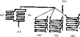
In another embodiment, the present invention relates to the integrating device water distribution system, this water distribution system is pure from water-supply source supply individually, fresh water to be to be used for process unit, and this system comprises:
A. realize with the water source that fluid is communicated with and from the safety shower water storage tank of water source supply water;
B. realize with the safety shower water storage tank that fluid is communicated with and from the first water dispenser loop of its supplied water;
C. realize the second water dispenser loop that fluid is communicated with the first water dispenser loop; With
D. be used for selectively extracting water out with the equipment of supplied water to the second water dispenser loop from the first water dispenser loop.
In another embodiment, the present invention relates to the method that dispensing water is passed the integrating device water distribution system, this water distribution system is pure from water source supply individually, fresh water to be to be used for process unit, and this method comprises:
A. water is fed in the safety shower water storage tank;
B. water is passed into the first water dispenser loop that is communicated with water storage tank realization fluid from the safety shower water storage tank;
C. will be passed into from the water of the first water dispenser loop selectively in the second water dispenser loop that is communicated with first water dispenser loop realization fluid.
In another embodiment, the present invention relates to the integrated vacuum system together used with the final polycondensation reactor that has independent high pressure, middle pressure and low pressure polycondensation vacuum section respectively, this system comprises:
A. spray condenser, this spray condenser realize that with the middle pressure of polycondensation reactor and in the low-voltage vacuum section each fluid is communicated with respectively;
B. realize the intermediate stage condenser that fluid is communicated with spray condenser; With
C. realize the vacuum pump that fluid is communicated with the intermediate stage condenser.
In another embodiment, the present invention relates to have at least in the integrated vacuum system together used of the final polycondensation reactor of the poly-vacuum section of compression and independent low pressure polycondensation vacuum section, this system comprises:
A. spray condenser, this spray condenser realize that with the middle pressure of polycondensation reactor and in the low-voltage vacuum section each fluid is communicated with respectively;
B. realize first EG nozzle that fluid is communicated with spray condenser;
C. realize the intermediate stage condenser that fluid is communicated with an EG nozzle;
D. realize the vacuum pump that fluid is communicated with the intermediate stage condenser; With
E. realize second EG nozzle that fluid is communicated with low-voltage vacuum section and spray condenser respectively.
In another embodiment, the present invention relates to collect from having the fluidic method of the final polycondensation reactor of high pressure vacuum section, middle pressure vacuum section and low pressure polycondensation vacuum section, this method comprises:
A. in the future autoreactor at least in the fluid of the poly-vacuum section of compression and low pressure polycondensation vacuum section be passed into respectively with middle pressure and low-voltage vacuum section in each realize in the single spray condenser that sealed fluid is communicated with; With
B. use with the intermediate stage condenser and realize the vacuum pump extraction fluid that fluid is communicated with and pass the intermediate stage condenser that is communicated with spray condenser realization fluid.
In another embodiment, the present invention relates to make the method for polyester monocase, comprising:
A. provide to have import, the tubular reactor of outlet and internal surface, this import is arranged on the below of outlet; With
B. near import at least a reactant is joined in the tubular reactor, so that reactant flows through this tubular reactor, wherein reactant reacts each other in tubular reactor and forms polyester monocase and this polyester monocase and leave from the outlet of this reactor.
In another embodiment, the present invention relates to make the method for polyester polymers, comprising:
A. provide to have first end, the polycondensation reactor of second end and internal surface, first end are arranged on second end, and this polycondensation reactor is non-linear between its first end and its second end; With
B. fluid polyester monomer is imported in first end of polycondensation reactor, so that monomer flow is crossed this polycondensation reactor, wherein monomer forms polymkeric substance and this polymkeric substance and leaves from second end of this reactor at the polycondensation reactor internal reaction.
In another embodiment, the present invention relates to make the method for polyester polymers, comprising:
A. provide to have first end, the polycondensation reactor of second end and internal surface, first end are arranged on second end, and wherein polycondensation reactor and vertical orientated planar shaped are angled, and this angle is greater than zero degree; With
B. the fluid monomer is imported in first end of polycondensation reactor, so that monomer flow is crossed this polycondensation reactor, wherein monomer forms polyester polymers and this polyester polymers and leaves from second end of this reactor at the polycondensation reactor internal reaction.
In another embodiment, the present invention relates to make the method for polyester, comprising:
A. provide to have import, the tubular reactor of outlet and internal surface, this import is arranged on the below of outlet; With
B. near import at least a reactant is joined in the tubular reactor, so that reactant flows through this tubular reactor, wherein reactant reacts each other in tubular reactor and forms polyester and this polyester and leave from the outlet of this reactor.
In another embodiment, the present invention relates to allow reactant reaction become the device of polyester monocase, comprising:
A. have import, the tubular reactor of outlet and internal surface, this import is arranged on the below of outlet; With
B. adjacent with the outlet of tubular reactor, as to be connected in the part of tubular reactor internal surface overflow weir.
In another embodiment, the present invention relates to allow reactant reaction become the device of polyester monocase, comprising:
A. have import, the tubular reactor of outlet and internal surface, this import is arranged on the below of outlet; With
B. be incorporated into the air-releasing mechanism in the tubular reactor, so that also flow through this air-releasing mechanism when the fluid that passes in the surface when the import of tubular reactor flows to outlet within it, this air-releasing mechanism comprises eccentric flat reducing pipe.
In another embodiment, the present invention relates to allow reactant reaction become the device of polyester monocase, comprising:
A. have import, the tubular reactor of outlet and internal surface, this import is arranged on the below of outlet; With
B. the recirculation loop that has influent end and effluent liquid end, this influent end is realizing that with tubular reactor fluid connected sum effluent liquid end is communicated with tubular reactor realization fluid near the outlet of tubular reactor near its import.
In another embodiment, the present invention relates to allow monomer reaction become the device of polyester polymers, comprising:
A. has first end, the polycondensation reactor of second end and internal surface, first end is arranged on second end, this polycondensation reactor forms as the interconnected section of a plurality of adjacency, wherein monomer flows along the internal surface of each section, to second end, wherein adjacent sections forms nonlinear angle each other from first end of polycondensation reactor; With
B. be attached at least one overflow weir on the internal surface of polycondensation reactor, one of them overflow weir is positioned at each joint of contiguous interconnected section.
The present invention is each and each method embodiment generator, and provides simultaneously and the relevant method of each device of the present invention.
Attendant advantages of the present invention will be partly set forth in below the detailed description, and partly obviously finds out from this narration, or learns by enforcement of the present invention.Advantage of the present invention will be by means of each key element of specifically pointing out in claims with in conjunction with being familiar with and realizing.The general remark and the following detailed description that it should be understood that the front all only are of the present invention giving an example and explanation, rather than come the restriction of the described scope of the invention of requirement as right.
Detailed description of the present invention
The present invention can be by the following detailed description of reference the preferred embodiments of the invention and wherein included embodiment and is understood with their front and describing below more easily with reference to the accompanying drawings.
At compound of the present invention, composition, goods, equipment, and/or before method is disclosed and describes, be appreciated that the present invention is not limited to specific synthetic method, and specific technology, or concrete device, these certainly change.Be understandable that also term used herein is used to describe the purpose of particular embodiment, effect without limits on meaning.
In this specification sheets and appended claim, will run into many terms, these are defined has following meaning.
As employed in specification sheets and claims, singulative " ", " a kind of " and " being somebody's turn to do " comprise plural indicator, unless context clearly indicates in addition.Therefore, for example, comprise one or more tubular reactors for the reference of tubular reactor.
Scope can here be expressed as from " approximately " particular value, and/or to " approximately " another particular value.When this scope was expressed, another embodiment comprised from a particular value and/or to another particular value.Similarly, on duty when being represented as approximation, by the use of antecedent " approximately ", be appreciated that this particular value has formed another example.Be understood that further the end points of each scope all is important for another end points, and keep independent with another end points.
" optional " or " randomly " refer to that incident or the situation described subsequently may or can not take place, and this description comprises situation that incident wherein or situation take place and their situations about not taking place wherein.For example, phrase " randomly heating " refers to that this material can or can not heat and this phrase comprises heating and heat-processed not.
Residue is meant a kind of structure division, it be in concrete reaction mechanism chemical substance the product that obtains or formulation afterwards or chemical products, no matter in fact whether this structure division obtain from this chemical substance.Therefore, the glycol residue in polyester is meant the one or more-OCH in polyester
2CH
2The O-repeating unit is no matter whether ethylene glycol is used to prepare this polyester.Similarly, the sebacic acid residue in polyester is meant the one or more-CO (CH in polyester
2)
8The CO-structure division is no matter whether this residue is to obtain when reacting the acquisition polyester by sebacic acid or its ester.
Just as used herein, the prepolymer reactor is first polycondensation reactor, typically under vacuum, and makes polymer chain length rise to the outlet length of 4-30 from the charging length of 1-5.This prepolymer reactor typically has the identical function that is applicable to all polyester, but some polyester have short object chain length, as 10 to 30.For these short object chain length products, do not need finishing reactor (the following definition), because this prepolymer reactor will provide the finished product.Finishing reactor is last melt phase polycondensation reactor, typically under vacuum, and makes polymer chain rise to required product chain length.
Here be meant non-tubular reactor or technology for polyester employed " common " technology of processing or device, include but not limited to, continuous stirred tank reactor (CSTR) (CSTR) technology or device, or reactive distillation, extracting or rectifying tower technology or device, or have internals, screw rod or malaxator the jar technology or device.The typical CSTR reactor that is used for common polycondensating process is knifing or film reactor.
In more detail with reference to the preferred embodiments of the invention, its example describes in the accompanying drawings now.As possible, identical Ref. No. is used in institute's drawings attached, refers to identical or similar portions.
The present invention includes the apparatus and method that reactant changed into polyester.More particularly, in one embodiment, in first step, the present invention allows starting raw material (being also referred to as raw material or reactant) be reacted into monomer (being also referred to as polyester monocase), then in second step, the present invention allows this monomer reaction become oligopolymer (being also referred to as polyester oligomer or prepolymer), is reacted into final polyester (being also referred to as polymkeric substance or polyester polymers).Be added in the first step if having the material of acid end group, as terephthalic acid or m-phthalic acid, then the first step is called esterification or reactor.If this starting raw material has methyl end groups, as dimethyl terephthalate (DMT) or m-phthalic acid dimethyl esters, then the first step or first reactor are step of transesterification or reactor.For the sake of simplicity, in whole specification sheets and claim, esterification and transesterify can be exchanged use and typically be called as esterification, but should be appreciated that starting raw material is depended in esterification or transesterify.Should be appreciated that also the output product of esterification technique also contains oligopolymer except containing monomer.This polycondensating process can be an integrated artistic or can be divided into two subdivisions again, the prepolymer technology and (finishing) technology that finishes.In this prepolymer technology, output comprises monomer, oligopolymer, and polymkeric substance, and wherein oligopolymer is typically in the highest flight.In the technology that finishes, typically the output product of this technology comprises oligopolymer and polymkeric substance, and the output product of major portion is a polymkeric substance.In this esterification technique, might allow a spot of polymkeric substance leave this technology.Similarly, in the technology that finishes, might allow a spot of monomer leave this technology.
Second step is called polycondensating process or polycondensation reactor.In this embodiment, the inlet plenum side of the first step or esterifier is at about barometric point or more leaves under the high pressure, and is monomer basically from the output product that is added in second step of first step.In second step, this conversion of monomer becomes oligopolymer, if desired, is separated in for example first pressure tripping device that it can be in reactor such as the pressure liftable device.If not separated, then this oligopolymer further changes into polymkeric substance in tubular reactor.
In selective embodiment, the inlet plenum side of first step is left (top that basically the prepolymer reactor is arranged on this transesterify or esterifier in one embodiment) under vacuum, with oligopolymer be that oligopolymer reacts and forms polymkeric substance in second step from the primary product of first step and separated or join in second step as raw material as final product.
The present invention has considered many different arrangements for different reactors.In one embodiment, esterifier is different with polycondensation reactor and isolating reactor.Monomer produces in esterifier, joins then in the polycondensation reactor and generates polymkeric substance.In another embodiment, the prepolymer reactor is set at the top of esterifier and forms device independent or that integrate, produces oligopolymer in view of the above from the esterification/prepolymer reactor of combination, joins in the polycondensation reactor then.Just as used herein, the integration for the combination of reactor is meant two set of reactors lumped together so that they realize directly each other that fluid is communicated with and this reactor basically each other and and other general reaction device system between can not distinguish.In another embodiment, this polycondensation reactor and esterifier form integrating apparatus.Reactant is transfused in the esterifier and final polyester polymers product is produced by integrating apparatus.In another embodiment, the use that combines with esterifier of prepolymer reactor is as two independent devices or as the single assembly of integrating.Oligomer product from the prepolymer reactor is separated as final product.In addition, the invention provides and be used to make monomeric esterification tubular reactor.In yet another aspect, the invention provides polycondensation pipe reaction apparatus and technology.When this esterification and prepolymer reactor are when forming as integrating apparatus, typically between these reactors, vapor pipe is arranged so that the discharge water by product; Therefore, this vapor pipe is as the point of crossing from esterification to the prepolymer reactor.
This technology is applicable to any polyester.This kind polyester comprises at least a dicarboxylic acid residue and at least a diol residue.More particularly, suitable dicarboxylic acids comprises the aromatic dicarboxylic acid that preferably has 8 to 14 carbon atoms, preferably has the aliphatic dicarboxylic acid of 4 to 12 carbon atoms, or preferably has cycloaliphatic dicarboxylic acid's acid of 8 to 12 carbon atoms.The example of dicarboxylic acid comprises terephthalic acid, phthalic acid, m-phthalic acid, naphthalene-2, the 6-dicarboxylic acid, cyclohexane dicarboxylic acid, cyclohexanediacetic, biphenyl-4,4 '-dicarboxylic acid, biphenyl-3,4 '-dicarboxylic acid, 2,2-dimethyl-1,3-propane diol, dicarboxylic acid, succsinic acid, pentanedioic acid, hexanodioic acid, nonane diacid, sebacic acid, their mixture etc.This acid constituents can be by their ester, as realizing with dimethyl terephthalate (DMT).
Suitable glycol comprises the cycloaliphatic diol that preferably has 6 to 20 carbon atoms or preferably has the aliphatic diol of 3 to 20 carbon atoms.The example of this type of glycol comprises ethylene glycol (EG), glycol ether, triglycol, 1; 4-hexanaphthene-dimethanol, propane-1,3-glycol, butane-1; the 4-glycol, pentane-1,5-glycol, hexane-1; the 6-glycol, dimethyltrimethylene glycol, 3-methyl pentanediol-(2,4); 2 hexylene glycol-(1,4), 2,2; 4-trimethylpentane-glycol-(1,3), 2-ethyl hexane glycol-(1,3); 2,2-diethyl propane-glycol-(1,3), hexylene glycol-(1; 3), 1,4-two-(hydroxyl-oxethyl)-benzene, 2; two (4-hydroxy-cyclohexyl) propane of 2-, 2,4-dihydroxyl-1,1; 3,3-tetramethyl--tetramethylene, 2,2; 4,4-tetramethylcyclobutanediol, 2, two (3-hydroxyl-oxethyl the phenyl)-propane of 2-; 2, two (4-hydroxyl propoxy-the phenyl)-propane of 2-, isosorbide; quinhydrones, 1,4-butyleneglycol succinate-(2; 2-(alkylsulfonyl is two) 4,1-phenylene oxygen base)) two (ethanol), their mixture etc.Polyester can be from the above-mentioned type glycol one or more preparations.
Preferred comonomer comprises terephthalic acid, dimethyl terephthalate (DMT), m-phthalic acid, dimethyl isophthalate, 2, the 6-naphthalene diformic acid dimethyl ester, 2,6-naphthalic acid, ethylene glycol, glycol ether, 1,4 cyclohexane dimethanol (CHDM), 1,4-butyleneglycol, polytetramethylene glycol, trans-DMCD, trimellitic acid 1,2-anhydride, hexanaphthene-1,4-dicarboxylic acid dimethyl esters, perhydronaphthalene-2,6-dimethyl dicarboxylate, the perhydronaphthalene dimethanol, perhydronaphthalene-2,6-dicarboxylic ester, 2,6-dihydroxymethyl-perhydronaphthalene, quinhydrones, hydroxy-benzoic acid, their mixture etc.Difunctionality (A-B type, its medial end portions is inequality) comonomer also can be included as hydroxy-benzoic acid.
Comonomer, with the same in the usual way, can beginning to polycondensating process from esterification being added Anywhere along this technology.Specifically, for the present invention, comonomer can add with upper/lower positions, these positions include but not limited to, import near esterifier, outlet near esterifier, at the import of esterifier and the point between the outlet, along the recirculation loop Anywhere, near the import of prepolymer reactor, near the outlet of prepolymer reactor, at the import of prepolymer reactor and the point between the outlet, near the import of polycondensation reactor, and at the import of polycondensation reactor and the point between the outlet.
It should be understood that also term polyester used herein attempts to comprise polyester derivatives, include but not limited to polyether ester, polyesteramide and polyether ester amides.Therefore, for the sake of simplicity, in whole specification sheets and claim, term polyester, polyether ester, polyesteramide and polyether ester amides can exchange use and typically be called as polyester, but should be appreciated that concrete polyester species depends on starting raw material, i.e. polyester precursor reactant and/or component.
The polyester that is formed by method of the present invention is polyester homopolymer and the multipolymer that is suitable for many application, and these application comprise wrapping material, film, and fiber, sheet material, coating, tackiness agent, moulded product, or the like.Food product pack is the particularly preferred purposes of some polyester of the present invention.In one embodiment, this polyester comprises the dicarboxylic acid component, the latter comprises terephthalic acid or m-phthalic acid, preferably at least about the 50mol% terephthalic acid and in some embodiments, preferably at least about the 75mol% terephthalic acid, and diol component, the latter comprises and is selected from ethylene glycol, cyclohexanedimethanol, glycol ether, at least a glycol in butyleneglycol and their mixture.This polyester may further include the comonomer residue, and content is one or more different dicarboxylic acids of about 50mol% at the most and/or one or more glycol of about 50mol% at the most, is basic calculation with 100mol% dicarboxylic acid and 100mol% glycol.In certain embodiments, the dicarboxylic acid component, diol component or about at the most separately 25mol% or at the most the comonomer modification of about 15mol% be preferred.In one embodiment, dicarboxylic acid comonomer comprises aromatic dicarboxylic acid, the ester of dicarboxylic acid, the acid anhydrides of dicarboxylic ester and their mixture.
In one embodiment, this reactant comprises terephthalic acid and ethylene glycol.In another embodiment, this reactant comprises dimethyl terephthalate (DMT) and ethylene glycol.In another embodiment, this reactant comprises terephthalic acid, ethylene glycol, and CHDM.
Preferred polyester comprises, but be not limited to the homopolymer and the multipolymer of polyethylene terephthalate (PET), PETG (with the PET of CHDM comonomer modification), PBT, Wholly aromatic or liquid crystal polyester, biodegradable polyester, as comprise those of butyleneglycol, terephthalic acid and hexanodioic acid residue, poly-(terephthalic acid cyclohexanedimethanoester ester) homopolymer and multipolymer, the homopolymer of CHDM and cyclohexane dicarboxylic acid or cyclohexane dicarboxylic acid dimethyl esters and multipolymer and their mixture.This polyester is to react the PET that makes by PTA and EG in one embodiment.In another embodiment, polyester is to react the PETG that makes by PTA, EG and CHDM.In one embodiment, this reactant does not comprise acid anhydrides.In one embodiment, this polyester is not polycarbonate or PBT (" polybutylene terephthalate "), or the polyester of making from Tetra hydro Phthalic anhydride or maleic anhydride.
Tubular reactor technology of the present invention also can be used for esterification, polycondensation, or both,, hydrogenation esterified for terephthalic acid wherein and polymerization form the technology of PET (or PETG, if also add CHDM), as applying for 60/228 at US, 695, (application on August 29th, 2000) and US application 09/812, disclosed in 581 (applications on March 20 calendar year 2001), both are hereby incorporated by reference for they.
Polyester of the present invention also can contain a spot of trifunctional or four functional comonomers, as trimellitic acid 1,2-anhydride, and TriMethylolPropane(TMP), pyromellitic dianhydride, tetramethylolmethane, or general known other polyester forms with polyprotonic acid or polyvalent alcohol in the prior art.Also can use linking agent or branching agent.In addition, though not necessarily, if desired, can use common additive used in polyester.This additive comprises, but is not limited to: catalyzer, tinting material, toning agent, pigment, carbon black, glass fibre, filler, impact modifier, antioxidant, stablizer, fire retardant, reheat auxiliary agent, acetaldehyde reduces compound, and oxygen is removed compound, UV absorption compound, barrier improves additive, as strip particle, one or more in the black iron oxide etc.
When terephthalic acid during as these reactants a kind of, typically purification of terephthalic acid (PTA) is as reactant rather than terephthalic acid (TPA) that does not purify or thick TPA (CTA), though TPA and/or CTA can be used among the present invention.
Technology of the present invention relates to melt polymerization, that is, method of the present invention is carried out in fusion mutually, and wherein reactant is in fluid state.This forms contrast with the solid condensation technology of using in some polyester process of prior art.Therefore tubular reactor technology of the present invention be suitable for fluid technology.Polycondensation of polyester technology of the present invention also is different from other polymer process, such as, emulsion-type polymerization, it typically need second kind or even other solvent, and polyester condensation does not need, and is different from olefinic polymerization, it needs not to be two-step reaction, and polycondensation is this situation.
This esterification can be finished or finish basically to technology of the present invention in the exit of esterification or polycondensating process.More particularly, the technology of the present invention's reaction, in every respect, can realize that at least 80% finishes, at least 85% finishes, and at least 90% finishes, and at least 95% finishes, at least 97.5% finishes, at least 99% finishes, and at least 99.5% finishes, and at least 99.9% finishes, wherein finishing is common used term in the prior art, and it refers to that 100 deduct the molecular fraction of residual carboxyl end group divided by non-acid end group.
When enforcement was of the present invention, the first step was preferably carried out in tubular reactor.Also preferably, second step (it carries out after first step) is to take place in the second identical or different tubular reactor.Yet the technician will appreciate that this esterif iotacation step can use common prior art processes to carry out, and this condensation polymerization step can be carried out in tubular reactor of the present invention then.Similarly, the tubular reactor of esterif iotacation step the application of the invention carries out, and condensation polymerization step can use prior art processes to carry out.According to the present invention, at least one in the middle of the first step or second step is to carry out in tubular reactor.
Basic pipe reaction apparatus used herein axially elongated typically, cylindrical device substantially, though shape may change, as square or rectangle, if do not damage purpose of the present invention.In some aspects, tubular reactor can be hollow or empty or hollow or empty pipe or pipeline basically simply.Here defined " hollow or sky " is meant that this pipe or pipeline do not have supplementary equipment therefore or internals, especially do not mix, transport or heat the inner part of this reactor or exhaust fluid, as agitator, static mixing element, be used to control protruberences or the mixing tank that this fluid flow distributes, weighting material, scraper, rotating disk, for example, be used for those of knifing or film reactor, retaining is pulled, column plate, upflow tube, spiral, or heating or cooling endless tube, they see common reactor and see in some tubular reactors.Hollow used herein or empty permission are provided with flow measurement device in pipe, as orifice plate, or flow rate control device, as control valve or overflow weir.In one aspect of the invention, this pipe or pipeline have slick internal surface.Tubular reactor of the present invention need not increase assembly at the inner surface-area of pipe, and it does not need film to form intensifier booster yet, and the latter uses in some tubular reactor designs of prior art.
For being used for of the present invention first and/or the tubular reactor of second step, the planner can consider desirable capacity, and quality stirs heat transfer area and isolating standard.This planner also can consider the working volume of reactor, heat transfer area, and circulating rate in the surface-area of liquid, vapour pipe, the reactor steam velocity enters reactor and the process flow rate of coming out and heat-transfer medium flow velocity and also can consider from reactor.More particularly, for the length of needed each caliber of each section of reactor, l can be by using reactor volume, and Vr and following formula calculate:
L=Vr/ (π r
2), wherein r is the pipe radius.
For the needed surface-area of each section, A can be calculated as follows:
A=2*1*SQRT(r
2-(r-h)
2),
Wherein h be the height of liquid in pipe and wherein r greater than h.
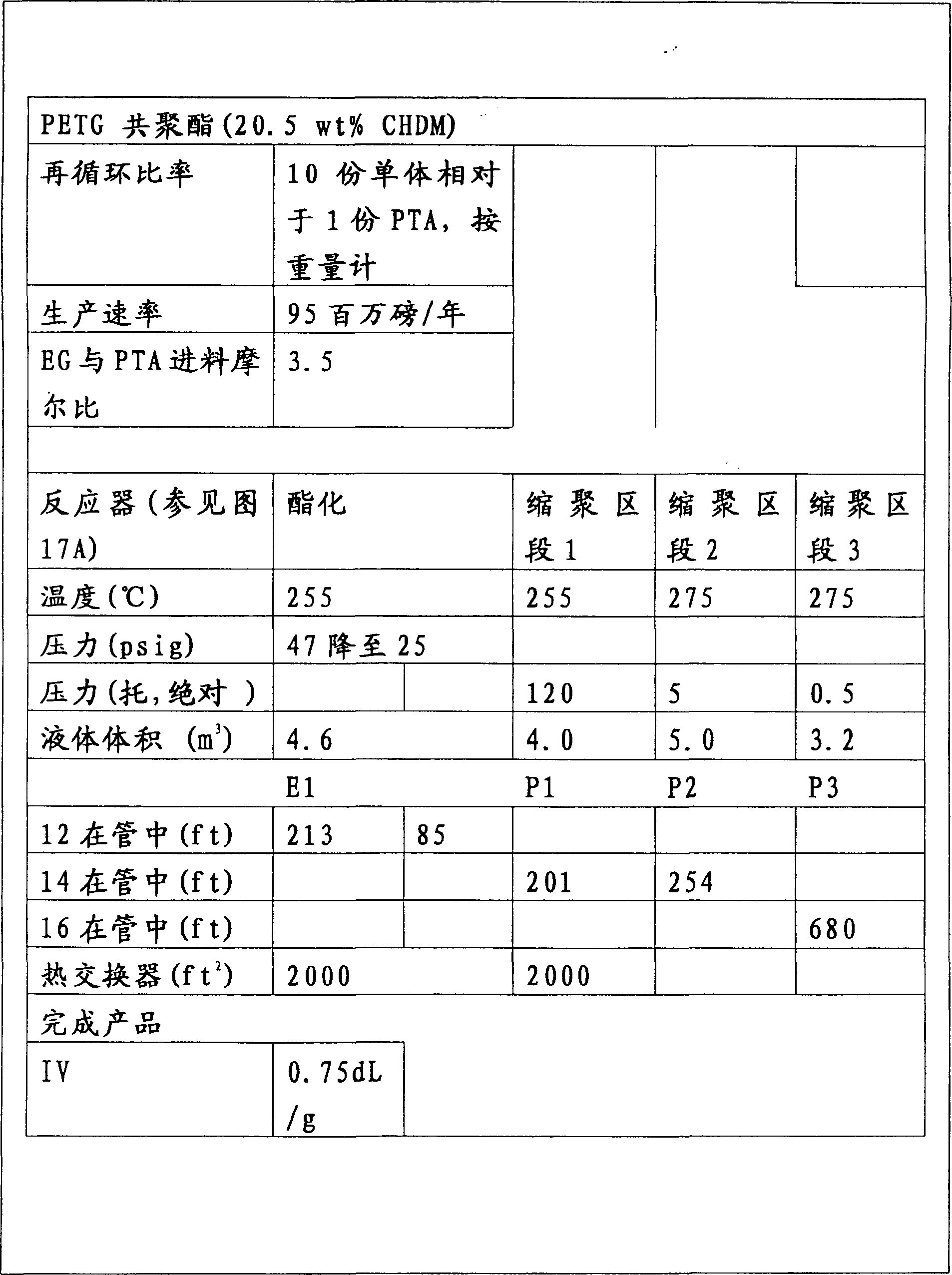
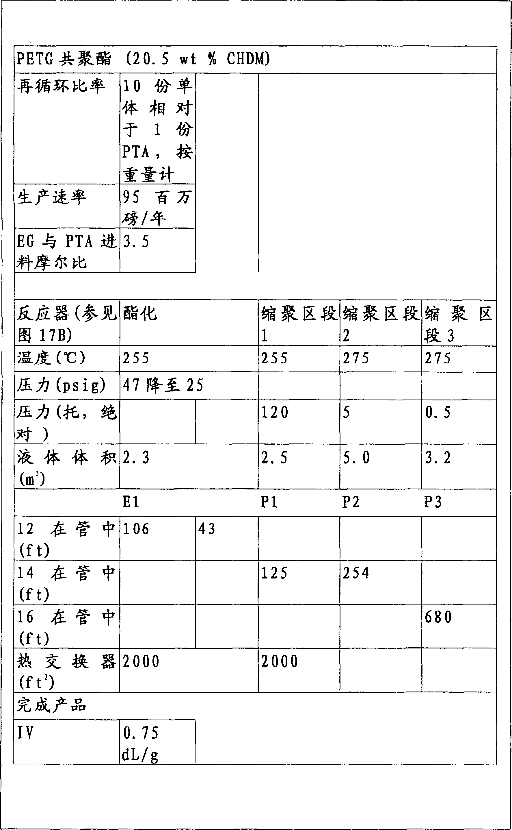
These calculating can be by considering heat transfer area, and velocity of steam (vapour stream in the most standard reactor is vertical, and in tubular reactor level typically) and technology flow rate are carried out repeatedly for each reaction section.Like this, can determine the length of each caliber.Fig. 3 contains the example of this calculating.Too little pipe size can produce the problem of spuming, and this foam can not break, and too big pipe size can cause the too big pressure drop of crossing over this fluid level.Reactor not only is subject to these standards, because other factors may cause the design of non-optimum cost, as the suboptimization of the surface-area of material property obtained or reactor.In certain aspects, this pipe size is 2 inches to 24 inches, preferred 6 inches to 16 inches, and more preferably 12 to 16 inches.
The use of tubular reactor in the present invention needn't change reaction conditions and the raw material of putting in the reactor.Yet reaction conditions can be different, in fact, can be improved for tubular reactor system of the present invention.In certain embodiments, the tubular reactor condition is compared with the reactor condition of prior art and is improved, and allows the enhanced performance, as higher degree product (for example, low DEG impurity) or improved color.
The technician can be that this type of operating parameters is determined on the basis with the art methods of making polyester, as starting point.In one aspect, the operational condition of prior art is 20-400 ℃ a temperature of reactor, the fusing point that preferably is higher than this body of fluid in any set point in set of reactors, pressure from the perfect vacuum to 500psig, about at the most 8 hours residence time, with 1.005: 1 to 6.00: 1 mol ratio, based on the mol ratio of diol residue and dicarboxylic acid residue, wherein should the acid residue based on ester and diol residue based on dibasic alcohol.Other prior art operational condition of these conditioned disjunctions can be improved and optimize to be used for tubular reactor design of the present invention.
Except that the summary of this routine, the Consideration of specific esterification and polycondensation tubular reactor technology and device will be discussed in more detail below and in some relevant with tubular reactor system of the present invention or irrelevant other invention with attribute.
Esterif iotacation step
For the following discussion below " esterif iotacation step " this joint, comprise whole trifle (pressure profiles, heating etc.), unless opposite indication is specifically arranged, technology of discussing in this joint below of the present invention and device similarly are applicable to and can be used in polycondensating process and device.
As already pointed out, the first step comprises that the use tubular reactor is reacted into monomer by starting raw material in one embodiment.In embodiment, tubular reactor 10 has import 12 shown in figure 2, outlet 11, outside surface, and internal surface.In one aspect, the internal surface of pipe is circle, square or orthogonal on cross section, circular, therefore formed interior diameter.
For esterification and polycondensation tubular reactor, this tubular reactor is not preferably by forming with the material of the material reaction that flows through internal surface, comprising, for example, steel, iron, alloy, titanium, hastelloy, stainless steel, carbon steel, nickel, aluminium, copper, platinum, palladium, lithium, germanium, manganese, cobalt, zinc or their binding substances.Other structured material includes, but not limited to glass, pottery has pipe and the plastics such as the acrylonitrile-butadiene-styrene resin (ABS) of lining, polybutene (PB), polyethylene (PE), polyvinyl chloride (PVC), chlorination PVC (CPVC), polypropylene (PP), glass fibre, tetrafluoroethylene, and reinforced epoxy.Usually use stainless steel, hastelloy and titanium, owing to their performance, property obtained and cost.For transesterify and polycondensation, catalytic material also can be used for this pipe.
In use, reactant typically near or near import (promptly comparing more near import) or be adjacent to this import (be in close proximity to import or in ingress) and be added in the tubular reactor with outlet.As the reactant that flows through this tubular reactor, this reactant reacts each other in tubular reactor and forms monomer, makes formed monomer leave from outlet.Yet not every reactant must be reacted into monomer (be some reactants be not reacted into leave outlet under the monomer) when import traverses into outlet, and this still belongs to the scope of the invention.The other monomer can react the formation oligopolymer, and this still belongs in the scope of the invention.Be added or the reactant that injects can be a liquid, gas, solid, or the form of slurry, or the mixture of other phase in the import that approaches or be adjacent to tubular reactor.
These reactants the easiest reactant added (for example EG and DMT) as liquid, because can directly pump into the import of tubular reactor independently or in the upstream of this import or another position in downstream.In a special design, a kind of reactant can be added through the import of tubular reactor with another kind of reactant and add in the upstream of import.In another special embodiment, one or more reactants can add in one or more positions along the length of tubular reactor between import and outlet through import interpolation and another kind of reactant.
When this reactant is fluid, can use pump, it discharges reactant being higher than under the pressure of barometric point, typically near the import of this tubular reactor.More particularly, pump can discharge reactant under the pressure that is enough to allow material run through this tubular reactor and leaves from outlet, and this comprises overcome friction or loss, and variation on potential energy (elevation) and prevention streams are crossed other power of tubular reactor.This pump can be any pump well known in the prior art, and its non-limitative example comprises impeller pump (comprising online centrifugal pump of vertical axis); Positive-displacement pump; Power (piston); Water screw (double end, single head, timing, in unlimited time); Rotation (gear, multiple-rotating screw, circumference piston, lore, rotary valve, or flexible member); Nozzle (injector single nozzle or multi-nozzle); Or bend pipe pump.These reactants separately pump take out or be pre-mixed and together pump take out.
Fluid reactant is pumped easily, and individually or mix, but solid reactant more is a problem.Just as discussed in more detail below, solid reactant can be by the use mashing pump, mixing tank, and unique mixing and feed system, with the recirculation loop of slurry tank integral construction, or the combination of these apparatus and method is added.Need enough mixing to be dissolved in any solid that exists in the liquid and to provide gas/liquid state to mix to drive this esterification.Preferably, gas/liquid mixture is in bubble or foam state in esterifier.
Pressure profile
In preferred embodiments, with in the place of contiguous outlet on internal surface the pressure of monomer and/or reactant compare, the pressure of reactant is higher or bigger on the internal surface of the place of adjacent entrance at tubular reactor.In order to realize this pressure reduction, the import of tubular reactor preferably requires in height to be lower than outlet (as shown in Figure 2) when being set up, and makes the hydrostatic pressure of the fluid generation that contained within the internal surface of tubular reactor partly cause pressure reduction.That is to say, between downstream and upstream position, exist hydrostatic pressure, make that this pressure can increase when fluid is upwards flowed through tubular reactor.This hydrostatic pressure is fluid density (temperature and a composition), voidage (the reactant of interpolation, temperature, the byproduct of reaction that produces, the gas volume of from reactor, removing), in reactor height between 2 or difference in height and since the pipe in mobile caused pressure drop (flow velocity, viscosity, the pipe diameter) function.
This esterification tubular reactor also can be taked different shapes.For example, in a kind of design (not shown), this tubular reactor is linear between import and outlet basically, makes that this tubular reactor is elongated in the axial direction.In another example, this tubular reactor is non-linear basically.In another example, this tubular reactor has the linear and nonlinear section of alternative.
This tubular reactor can be a perpendicular, level, or any angle of between.This tubular reactor orientation can form any angle with vertical surface, from 0 degree (vertical, promptly perpendicular to ground or base) to 90 degree (level or be parallel to horizontal plane).In every respect, this tubular reactor can have 0 ° with vertical surface, and 10 °, 20 °, 45 °, 60 °, 75 °, 85 °, the angle of 89 ° or 90 °.The orientation angle of this tubular reactor and vertical surface depends on many conditions, particularly the product that will make and desirable pressure distribution.For example produce for PET, if use terephthalic acid, horizontal alignment is preferred, and if use DMT technology, vertical orientated is preferred.For PETG, vertical orientated is preferred.
In each embodiment, this esterification tubular reactor can have vertical configuration.In each embodiment of this type of vertical configuration, the import of tubular reactor can be positioned at least 20,50,75,80,90 of outlet vertical lower, or 100 feet.In other embodiments, this import can be positioned at 20 to 200,50 to 200,50 to 175,90 to 150 of outlet vertical lower, or 100 to 140 feet.
It is non-linear tubular reactor that another same promising design is included between import and the outlet.A kind of such design is shown among Fig. 2, and wherein this tubular reactor is the meander-like in front plan view.Other form of nonlinear tubular reactor includes, but not limited to following design: reverse; Twine; Bifilar winding; Coil pipe; Twist and warping; Around (curvilinear motion); Spiral; Distortion; Tortuous; Corner; Crooked; And/or labyrinth type.
In another design, this tubular reactor extends to outlet along non-linear, level trend from import, vertically extend to another horizontal plane with another non-linear horizontal plane trend then, and this process can repeat to required any height (and width/height).This has produced has the stack design that stratiform is non-linear, level is moved towards.
In selective embodiment, this esterification (or polycondensation) reactor can be a series of vertical section (rises) up and down.Specifically, this esterifier (or polycondensation) is suitable with Fig. 2's, turn 90 degrees but revolve.Promptly with reference to Figure 16, this starting raw material is advanced by pump at 12 places, and with the alternative form vertically upward and vertically downward.This design allows charging enter under pressure, moves towards low pressure then and returns high pressure, and front and back alternately subsequently.Steam can be removed in the low pressure section.Effluent liquid leaves at 11 places.
In these nonlinear designs, this tubular reactor is preferably included in a plurality of bend pipes that are provided with between import and the outlet.These bend pipes constitute the angle of 45 (45) or 90 (90) degree usually, but other angle also can be considered.When reactant and/or monomer ran through this bend pipe, each bend pipe changed the flow direction in tubular reactor.The mobile direction can be with respect to the ground of stationary water plane such as buildings, or with respect to the wall of static vertical surface such as buildings, or change with respect to stationary water plane and vertical plane.When this reactant and monomer flow were crossed this bend pipe, comparing material with the straight-line segment of tubular reactor had better mixing.
Also can consider to design this tubular reactor to obtain desirable pressure distribution.Technician in the art will appreciate that, when reactant and/or monomer were in liquid form, the pressure of liquid was constant at it when the part of the tubular reactor of horizontal alignment flows basically.That is, there is not the hydrostatic pressure difference along the horizontal section of tubular reactor, but generation frictionloss when the flow direction downstream, and this will change along the pressure of the horizontal section of tubular reactor.On the contrary, when this part of tubular reactor is when being orientated in the mode that more vertically flows to the downstream, fluidic pressure then descends with the speed that increases.
With reference now to Figure 10 and 11,, these engineering philosophies can be used in embodiment of the present invention so that reactant and/or the monomer that flows through this tubular reactor produced required pressure distribution.The distribution plan 21-25 of Figure 11 is corresponding to the view 21-25 of Figure 10.The configuration that changes this pipe can change this pressure distribution.Figure 10 and 11 is correct on principle, but in fact, only reduces by the frictional pressure drop along length of tube along the pressure drop of level pipe.The only vertical dimension of level pipe can cause the quite low pressure in tubular reactor, therefore occurs main pressure drop in upright or vertical orientated section.Therefore, the Figure 11 that has described pressure and length or time relation is in fact with pulse mode, rather than occurs in described dullness (monatomic) mode.Each configuration is described in this understanding with sketch.The view 21 of Figure 10 is a series of equally spaced pipes, if fluid density and voidages such as hypothesis, they cause the linear voltage drop in reactor.View 22 has shown tubular reactor, is beginning to have less pressure drop and in back four reactor segment of widening spacing big pressure drop is being arranged.The tubular reactor of describing in the view 23 of Figure 10 has big initial drop, and this is produced by the vertical component that increases and the less pressure drop in back four sections of reactor.View 24 has shown the tubular reactor with four sections, and each section has little pressure drop and big pressure drop is arranged between each section.View 25 designs allow this reactor to reduce pressure step by step.As indicated like that, be shown among Figure 11 as distribution plan 21-25 with diagramatic way for the pressure distribution of view 21 to 25.Should be realized that configuration described here is only to give an example.Many other configurations can design according to principle discussed herein.
In another embodiment, can consider with the roughly the same vertical height of outlet on import (promptly the tubular reactor of horizontal alignment) is haply arranged, so that will be greater than the pressure of outlet at the pressure of import, this be owing to existing frictionloss when material is mobile along the internal surface of tubular reactor.Pressure reduction between import and outlet will be bigger like that than that example of the import that exports higher (vertical height) not as having.Though be unfavorable design, also within the scope of the present invention be with reaction tubes orientation, make import on vertical height, be higher than outlet.
Along with fluid upwards flows under vacuum, the pressure in the top of esterifier will be under the vacuum.In one aspect, before this vacuum section, vapor pipe can be used for removing most water.In this embodiment, the first part of polycondensation reactor will be placed on the top of esterifier.This will make this device technique become littler, and the part of this polycondensating process/device is in the esterification side.In another embodiment, also can save the longest seal leg in this equipment.In addition, in yet another aspect, heat exchanger can be used for this reactor line after vapor pipe.
Heating
The reacting by heating thing can improve speed of reaction, helps forming monomer and polycondensation takes place.Therefore, another optional feature of the present invention is to be used to heat reactant and/or the monomeric device that runs through tubular reactor.And, heat this material to boiling meeting along the internal surface of tubular reactor and strengthen by the following mixing: (1) by the formed gas of boiling and along produce between the tubular reactor mobile surrounding liquid (or solid) buoyancy difference and (2) break by the internal surface of tubular reactor and with material that internal surface contacts between the frictional belt that frictional force produced.In every respect, at least some fluids in esterification technique, polycondensating process or esterification and polycondensation two technologies are heated to boiling, to obtain effective mixing.In others, at least some fluids can utilize alternate manner, as by reducing system pressure or adding than needing the ebullient fluid that the more component of high-vapor-pressure is arranged, are adjusted to boiling.Those of skill in the art will appreciate that (i.e. the generation of bubble or bubble post alone) has the highest rate of heat transfer for nucleate boiling, but also considers the boiling of other type.
Below table provide the present invention the boiling point of illustrative component to be processed.Certainly, other component except that following cited those also can be used:
| Component | Boiling temperature (℃) |
| Acetate | 118.5 |
| Hexanodioic acid | 330 decompose |
| M-phthalic acid (IPA) | Distillation |
| Phosphoric acid | 213 |
| Terephthalic acid | 301.4 |
| Methyl alcohol | 64.5 |
| The 1-butanols | 117.8 |
| Virahol | 82.5 |
| Titanium isopropoxide | 82.5 |
| Titanium dioxide | 73000 |
| Trimellitic acid 1,2-anhydride | 390 |
| Zinc acetate | 100 loss water, distillations then |
| Weisspiessglanz | 1100 |
| Cobalt acetate tetrahydrate | 140 |
| 1.4-cyclohexane dicarboxylic acid dimethyl esters | 265 |
| Dimethyl isophthalate | 282 |
| Dimethyl terephthalate (DMT) (DMT) | 288 |
| Butyleneglycol | 230 |
| Cyclohexanedimethanol (CHDM) | 284-288 |
| Glycol ether (DEG) | 245 |
| Ethylene glycol (EG) | 197 |
| Triglycol | 290 |
The heating installation of tubular reactor can be taked a lot of forms.This tubular reactor can heat by the multiple medium that flows through each surface.More preferably, the present invention includes heat-transfer medium (" HTM "), it and realize type of thermal communication along the outside surface of at least a portion of tubular reactor this tubular reactor between its import and outlet.This heat-transfer medium can be around the whole external diameter of this outside surface and the total length of extending this tubular reactor basically.Also can be by inserting interchanger or heating by the reactant that adds heat or be under the steam condition.In one aspect, in PET or PETG technology, this ethylene glycol and/or CHDM can add while hot or with steam condition.Additionally, can use induction heating or microwave heating.
Heat exchanger can be used in the reactant feed lines with heating or vaporized reactants.Heat exchanger can also use in the middle of this tubular reactor, and wherein this tubular reactor is in different section neutralizations and is imported into heat exchanger to heat this reactant and/or monomeric unit from each effluent liquid of each section.This heat exchanger in this tubular reactor system is particularly useful, if tubular reactor uses the pipe of no chuck.Heat exchanger can be the low-cost assembly of set of reactors, and this depends on the installation costs of telescopic installation costs and interchanger.Typically, in this esterification and early stage polycondensation, the fluidic temperature control residence time, therefore the heat input is the restrictive design factor, rather than reaction kinetics.So in order farthest to reduce volume and expense, heating fast can be quickened this technology.Interchanger can insert in any position alongst, as import and outlet centre or close or adjacent entrance or outlet at esterifier, polycondensation reactor or recirculation loop, or between any reactor (between esterifier, between polycondensation reactor, or between esterification and polycondensation reactor), contiguous or near any one import or export of this esterification or polycondensation reactor, or close, contiguous or in any seal leg.Preferably, heat exchanger is positioned at the beginning of each reactor segment, and wherein pressure changes, because this fluid is cooled off in the Evaporation meeting.Therefore, as described below, it is favourable that close or contiguous this seal leg inserts heat exchanger.Be not used for esterification if there is the pipe of chuck type, then selecting cheaply is bringing into use heat exchanger and using additional heat exchanger so that along with the by product evaporation temperature is fallen after rise along the length of reactor at esterification technique.In one aspect, this interchanger in the beginning of esterification technique by intensive and widened distance after a while, because in the beginning of esterification, the amount of the by product of evaporation is bigger.
An example of heat-transfer medium comprises a plurality of electric heating assemblies of the outside surface that surrounds tubular reactor.Also consider to use the sleeve pipe that surrounds outside surface, wherein this sleeve pipe has than the bigger internal surface of the outside surface of tubular reactor so that at periphery formation annular space.Heat-transfer medium comprises for example liquid, steam, and steam, superheated water, pressurized gas, the steam gas of condensation, the solid of conveying, electrical tracing, electric heating assembly, or their associating are located within this annular space.(that is) use, liquid, steam, or steam, annular space should seal in the horizontal, makes fluid vertically flow between this import and outlet for fluid heat transfer medium.More particularly, hope is used fluid heat transfer medium in this embodiment, the direction of the flow direction of this fluid in annular space and the material that flows through tubular reactor is opposite (to be that heat-transfer medium flow to import from outlet, because reactant and monomer from inlet flow to the outlet), though and flow the HTM flow path and also can use.
Based on this heat-transfer medium flow velocity, the planner must guarantee that the speed of heat-transfer medium in the annular space between process pipe and sleeve pipe belongs to the appropriate speed of good piping design.For present patent application, about four are commonly considered as suitable to the speed of about 18 feet per second linear speeds.If this speed is too high, then casing diameter must increase.
What also can imagine is, heat-transfer medium can also flow through pipe in this or be within the pipe and process fluid be among the annular space between the internal surface of the outside surface of pipe and outer tube.This design can reduce the surface-area of process pipe and need bigger outer tube, then is useful for some heat-transfer mediums as high-pressure medium still.The HTM while is inside and outside process fluid, and process fluid can increase more area among the intermediary annular space.
If wishing has more heat transfer in the section of reactor, then surface-area and technology volume ratio must increase.This follows and uses the more process pipe of minor diameter.Less process pipe will increase the technology linear speed, but as long as this flow velocity is unlikely high to be caused corrosive pipeline and be not in the disengaging section of tubular reactor to it, then be acceptable.The section of these high surface area will influence the cost of tubular reactor.If this process flow rate is too high, then should use a plurality of parallel pipes.
The degassing
From inlet flow in outlet, reactant, monomer, oligopolymer, polymkeric substance and by product are will be because of chemical reaction, heating or other former thereby form steam or gas.The present invention is also optional to be comprised and is used near outlet or contiguous exit, removing the equipment of steam from tubular reactor in the middle of the import of tubular reactor and outlet and/or in the exit.This is removed and helps to drive this reaction and reach favourable balance and/or control and flow mutually and reach desirable state.In some aspects, this to remove the position can be in the terminal of one or more or whole sections (" section " refer to esterification section and each polycondensation section) and/or the one or more positions within each reactor segment.
Referring to Figure 20 A, eight kinds of different flow states of the two-phase flow in level pipe have been shown.On behalf of liquid and clear zone, the dark space represent gas.At the burble state, the bubble of gas moves along the top of pipe, and roughly the speed with liquid is identical.In plug flow regime, the alternative piston flow of liquids and gases moves along the top of pipe.At the stratified flow state, liquid flows along the bottom of pipe and gas flows up, on level and smooth liquid/gas interface.The ripple formula flows and to be similar to laminar flow, and just gas moves the interference that is subjected to the ripple propagated at flow direction with the interface with higher flow velocity.In slug (slug) stream mode, this roll wave is carried secretly and is formed slug by the gas of rapid movement more, and it is to pass pipeline under a kind of speed that is higher than average liquid rate.At the annular flow state, gas is flowing as prostheses down high-speed liquid so that the form of film around inside pipe wall is mobile.This surface neither be level and smooth neither symmetric, and be similar to the roll wave that is superimposed on the high velocity air (squalls), points out as flowing for the ripple formula.In dispersion or fog flow, most liquid is carried secretly by gas as spraying.This spraying seemingly by the crest that the liquid splitting left this roll wave high-speed gas produced.Foam flow is similar to burble, and bigger bubble or voidage are only arranged.Referring to, Robert S.Brodkey, " The Phenomena of Fluid Motions ", Addison-Wesley Series inChemical Engineering, 457-459 page or leaf, 1967.
For esterification technique of the present invention, foam flow in tubular reactor or burble are the best modes of operating therein, because it provides the well blend of steam and liquid to be beneficial to this reaction.For condensation polymerization step of the present invention, the laminar flow in tubular reactor is the optimal flow mode, because it provides the good segregation of vapor byproduct from this liquid product.Laminar flow also is the optimal flow of the venting of tubular reactor of the present invention in esterification or polycondensation.As can be seen, it is the Baker curve of the ratio (Bx) of vapor quality flow (By) and liquid mass rate from Figure 20 B, has shown the various flow states of two-phase flow in level pipe.For the Baker curve of two phase flow, generally referring to for example US patent 6,111,064.As mentioned above, foam flow or burble are best for esterification technique, and laminar flow is best for the prepolymer and the aftercondensated step of polycondensating process.Slug and piston flow may cause equipment damage, and annular and distribution (disbursed) provide the too low residence time, and the ripple formula is mobile process liquid are entrained in the air-flow, and this causes the fouling in gas processing device.
In certain embodiments, in the early part of esterification, solid can exist, and this can produce three-phase stream.Yet above-described optimal flow state and liquids and gases have relation.Solid does not in fact influence the gas/liquid stream mode, but is noted that if there is solid, it can not be real two-phase flow in order to obtain transparency, because there is the 3rd (solid) phase.
Motion between fluid state can be by changing plant capacity, improve recirculation rates, the position is removed in the recirculation of change in this technology, the discharging steam, change caliber, use parallel pipe, utilize the measure such as temperature, pressure, composition to change physical parameter, add thinner or inert component, or realize by alternate manner.
Referring to Figure 20 B, for esterification technique, in order to move on the right-hand lay of figure, this recirculation can improve on amount or ratio to realize foam shape or blister.In order on figure, to move upward, use pipe than minor diameter.To left movement, can use additional path.For this polycondensating process, if this steam velocity is too high, then additional parallel pipe can be increased and reduce steam velocity, to obtain stratified two-phase flow state.
Figure 24 has shown that the present invention makes one group of possible two-phase state of an example of PET homopolymer method.In this embodiment, 400 places begin this esterifier in the site under foam or blister attitude, and carry out along with this technology runs through this reactor, move to site 401 lentamente.402 places, site in the stratified flow section, biphase separates and to have reduced speed, runs through the first pressure zone separator then, and seal leg for example enters into polycondensation fs at 403 places in the site.This technology proceeds to site 404 along path, until having arrived the second pressure zone separator, makes flow state move to site 405.This technology is advanced along path and is passed site 406, arrives final pressure segments apart device.Final polycondensation section do not show, because it is on this diagrammatic scale, but has and starts two patterns that section is identical.
In addition, can control the ratio of steam flow and liquid stream from system's emission gases.Exhaust can be removed steam.This makes this technology move downward (less steam flow) and to left movement (ratio of higher liquid/gas).Following embodiment has shown certain methods, and they are used for moving on any in the drawings direction to change flow state.
Entrained gas can reduce by the control of rate of flow of fluid in degassing body skin (enclosure), together with the control discharging of collecting gas from degassing body skin, discharges from the liquid that pump is taken out.More preferably, have been found that the gas that is embedded can separate by introduce the degassing pipeline of certain-length in the stream of fluid stream in fluid that pump is taken out stream, and discharge institute's gas separated from the liquid that pump is taken out by standpipe or flow control vapor pipe.Term used herein " is embedded " and similar terms, is meant the not gas dissolved that exists in fluid; For example, the gas in fluid presents bubble, microvesicle, foam, forms such as foam.
In a present embodiment preferred, this vapor discharge equipment or degassing equipment comprise vapor pipe or the air-releasing mechanism that is incorporated in the tubular reactor.Air-releasing mechanism should make after the location and also flow through this air-releasing mechanism by reactant and the monomer that all or part of runs through when from inlet flow to outlet within the tubular reactor internal surface.
Referring now to Fig. 7 a-7f,, this air-releasing mechanism is used for slowing down reaching in the reactant of tubular reactor and/or monomeric speed is enough to allow entrained gas isolating a kind of degree from this fluid reactant and/or monomer.This air-releasing mechanism preferably produces laminar flow, stratified flow, non-circular stream, two-phase gas/liquid flow., desirable two-phase (gas/liquid) stream in air-releasing mechanism, reduces the size and the fluidic viscosity of the bubble that the degree of speed can may exist by use (1a) by in the art technician for being provided, or (1b) flow velocity that flows through this tubular reactor expected of both physicalies of these liquids and gases and (2) is determined.The interior dimensions of air-releasing mechanism is through providing the cross-sectional area for fluid conveying usefulness bigger than the cross-sectional area at the contiguous air-releasing mechanism of tubular reactor place after selecting.Based on the mass velocity principle, because internal diameter increases, the speed of constant current speed can descend.For slower speed, gas can rise and overflow from solution, till the pressure of the gas that is discharged stops extra gas to be overflowed from solution.The gas that discharged of discharging can make additional gas overflow from solution because the gas in solution and from solution between the escaping gas the initial balance that exists be offset.
Separation for disclosed entrained gas in reactant and/or monomer in disclosure thing, for example, wish that this air-releasing mechanism reduces the flow velocity that fluid flows through, make and preferably in esterification technique, realize foam shape or blister two-phase flow state and preferably in this discharging and polycondensating process, realize layering two-phase flow state.The residence time of fluid in air-releasing mechanism also controlled by the suitable selection of air-releasing mechanism length, to allow under the speed that slows down time enough being arranged in air-releasing mechanism, makes entrained gas fully separate from liquid.The suitable residence time for concrete fluid stream can be determined by experiment or according to experience by those skilled in the art.
In order to obtain best result, this air-releasing mechanism substantial horizontal is provided with or orientation so that the reactant that flows through it and single intravital steam and gas will essentially horizontally flow and top area at air-releasing mechanism in collect.The attribute of desirable air-releasing mechanism makes that escaping gas is captured by any designing institute from solution, and this design can allow liquid pass through on the bottom but restriction gas flowing in the top.
Be used for including, but are not limited to those in Fig. 7 a-7f from several designs of liquid reactants and monomer gas delivery.Each embodiment in Fig. 7 a-7f has the import 31 that receives this fluid and gas/steam mixture, fluid outlet 32, T shape pipe 36, and gas/vapor outlet port 33.This air-releasing mechanism can comprise that the flat reducing pipe 37 of eccentric circle enters the speed of stratification state and farthest reduces this liquid entrainment in steam with this fluid that slows down.
This reducing pipe allows to have a certain amount of surface-area, make that the steam velocity on liquid level is sufficiently slow, this steam can traction liquid when steam discharges like this, with have enough fluid path cross-sectional areas, make linear speed enough slow, vapour bubble utilizes the buoyancy difference to separate from liquid, causes that two are separated.When for caliber or reactor capacity without limits the time reducing pipe be preferred.If caliber is limited plant capacity without limits, the replacement scheme of reducing pipe provide the pipe and be parallel so that lower linear speed and bigger surface-area are provided on shorter path length.
This air-releasing mechanism preferably has the validity internal diameter bigger than the internal diameter of tubular reactor (or bigger flow area).Speed can also reduce at a plurality of parallel pipes shown in Fig. 7 f by using.In one aspect, the reducing pipe that the system of Fig. 7 f need be in import.The overflow weir at enough 38 places of the configurational energy in Fig. 7 e and 7f (reverse overflow weir) further strengthens, and it is in upper part of T shape pipe 36 and the pipe between the ell on T shape pipe the right.
When overflowing the solution in air-releasing mechanism when gas and steam, they must be removed.For this purpose, this air-releasing mechanism preferably further comprises the upright degassing standpipe that is connected in air-releasing mechanism.This degassing standpipe has receiving end that is communicated with air-releasing mechanism realization fluid and the relative exhaust side in position that is higher than inlet end on vertical height.Though consider the straight line embodiment, preferably, this degassing standpipe is non-linear between receiving end and exhaust side.
In one embodiment, this vapor pipe further comprises the vertical type degassing standpipe that is connected in vapor pipe, the standpipe that wherein outgases has with vapor pipe realizes receiving end that fluid is communicated with and the opposition side exhaust side that vertically is provided with on inlet end, the standpipe that wherein outgases vertically non-linearly extends along it between receiving end and its exhaust side, the standpipe that wherein outgases is made up of three adjacent segments that realize the fluid connection each other, first section adjacent with receiving end and substantially perpendicularly extend from vapor pipe, second section is connected in first section and be orientated from the plane with the certain angle with respect to first section, with the 3rd section be connected in second section and be orientated from the plane with certain angle with respect to second section, make the 3rd section horizontal alignment basically.In one aspect, this vapor pipe is the first section standpipe that is connected in the 3rd section level pipe, and second section pipe preferably connects the vertical and horizontal pipe with the miter angle degree with any angle except 0 or 90 degree.In every respect, vertical substantially, with respect to first section, comprise that first section with the angle with respect to about 60 degree of the about 0-of vertical surface, with respect to the angle of about 50 degree of the about 0-of vertical surface, angle with respect to about 45 degree of the about 0-of vertical surface, with respect to the angle of about 30 degree of the about 0-of vertical surface,, or spend (vertically) and be orientated with respect to about 0 of vertical surface with respect to the angle of about 15 degree of the about 0-of vertical surface; Second section with respect to about 85 degree of about 5-of vertical surface, about 75 degree of about 15-, and about 30-about 60 spends, or about 45 angles of spending and being orientated; Level substantially for the 3rd section, comprises with about 0 degree of plus or minus about 45-with respect to the horizontal plane, about 0 degree of the about 30-of plus or minus, and about 0 degree of the about 15-of plus or minus, the about 5-of plus or minus about 0 spends, or about 0 angle of spending and being orientated.Plus or minus with respect to the 3rd section refers to that on meaning first and second sections typically are provided with the certain angle with respect to vertical surface, feasible steam that flows through or gas stream are along march forward upward (liquid upwards advances at first but moves along downward direction at complete after separating then and get back in this technology), and the 3rd section can be along upwards, level, or downward orientation is oriented.In yet another aspect, first section with respect to about 0 Du of vertical surface-Yue 60 degree angular orientation, and second section with the about 85 degree angular orientation of about 5-with respect to vertical surface, and the 3rd section be orientated with respect to the horizontal plane the about miter angle degree of about 0-.In yet another aspect, first section is with 0 degree angular orientation with respect to vertical surface, and second section is to be 0 degree angular orientation with respect to the horizontal plane with respect to the miter angle degree of vertical surface orientation and the 3rd section.Preferably, first section is to be with the about miter angle degree orientation with respect to second section with the orientation of the about miter angle degree with respect to second section and the 3rd section.Preferably, the 3rd section production line that is communicated with the realization fluid keeps and stream, as shown in Fig. 7 g, if the equipment of Fig. 7 g exports 33 therein and is connected on Fig. 7 a-7f of import 34 and directly is provided with or puts upside down, then be illustrated, or (suppose that element 137 is on the plan view plane identical with T shape pipe 36 or 139) as shown in Figure 8.Yet the 3rd section can be adverse current, or even and stream and adverse current between point.Adverse current can provide more effective separation, but exists the equipment layout defective.Therefore, this degassing standpipe has produced from first section to second section non-linear paths with then from another nonlinear path of second section to the 3rd section.In yet another aspect, the 3rd section is the negative miter angle degree setting with respect to the horizontal plane, produces the path and for this on the one hand of flowing downward in the 3rd section, preferred the 3rd section is to be orientated with an angle of 90 degrees degree with respect to second section, and it is preferably with the miter angle degree orientation with respect to vertical surface.This vapor pipe is the very low cost configuration of performance separation function, does not have moving parts in the basic piping design of vapor pipe, and vapor pipe only is empty pipe.
As shown in Fig. 7 g and Fig. 8, the preferred embodiment of degassing standpipe is to form in section at three that realize the fluid connection each other: the contiguous receiving end of first section also vertically extends from this air-releasing mechanism substantially; Second section be connected in first section and from the plane with the orientation of the about miter angle degree with respect to first section; Be connected in second section with the 3rd section and from the plane with about miter angle degree orientation with respect to second section, make the 3rd section orientation flatly substantially.
Therefore the common feature is that this standpipe vertically is orientated and this air-releasing mechanism flatly is orientated, and this has produced the non-linear paths from import to outlet and make gas evolution but liquid that can not flows out from standpipe.Referring to Fig. 7 g or Fig. 8, air-releasing mechanism is arranged and to be equally applicable to this esterification technique, length of tube 136 and 145 through overregulate up to the linear passages from assembly 144 (or the import 34 among Fig. 7 g) to assembly 137 become impossible till.Therefore, there is not linear passages in import 34 with between exporting 35.This non-linear meeting causes that whole or most of droplet impacts in the steam are on some surfaces of vapor pipe.Therefore, Fig. 7 a-7f has shown that six different steams separate arrangement, Fig. 7 d, and the embodiment of 7e and 7f is most preferred, because they do not have depression points, the latter is deleterious in emissions operation.In each example of Fig. 7 a-7f, the example of Fig. 7 g gases/vapors import 34 is that the outlet 33 with the discharging " T shape pipe " 36 of Fig. 7 a-7f realizes that fluids are provided with communicatively, makes steam at first advance and passes the vertical section of Fig. 7 g, passes diagonal segments then, pass horizontal section then and leave from exporting 35.
Also wish to comprise that in the degassing flow rate control device crosses the fluidic flow of this pipe with controlling flow in the standpipe.This flow rate control device can be, for example, and orifice plate; Reducing valve; Control valve; Manual valve; The reducing pipeline section; Top hole pressure control; Nozzle; And/or pass the bubble of the pressure head that liquid forms.
This flow rate control device preferably causes about 90 percent of in this distance of the tubular reactor steam that produced to pass through, and remaining 10 kept by liquid.This percentage of about 90/ten has guaranteed that liquid does not pass gas piping and kept about 10 gas to sneak in this tubular reactor.The amount of the gas that is produced can not be near one of maximum value percentage hundred, because liquid can flow in the standpipe with gas.
The exhaust side of degassing standpipe typically realizes that with Distallation systm (steam flow cross it or by emptying) fluid is communicated with.Also might be in environment with vapor discharge.When exhaust side and Distallation systm are realized circulation, can be controlled at the pressure at the exhaust side place of degassing standpipe, and when being discharged into environment, exhaust side is under the barometric point.
Those of skill in the art will appreciate that, the efficient that steam is removed can be improved by the internal diameter that increases contiguous this air-releasing mechanism and the tubular reactor before this air-releasing mechanism, locates lip-deep steam velocity with surface-area that farthest improves liquid and half that farthest reduces at caliber.If the speed in pipe is too high in isolating vicinity, then caliber will be according to for example expanding shown in Fig. 7 d.In some embodiments, this expanding reach preferably has the flat reducing pipe of eccentric circle, to prevent forming air pocket in reactor.Therefore these air pockets have reduced reaction area, have reduced ability and can not easily get rid of in technology.Can catch liquid and make and when device is shut down, can discharge fully at the configuration shown in Fig. 7 d and the 7f.This air-releasing mechanism can have the identical size of pipeline that is connected with it, littler or bigger diameter.In one aspect, this vapor pipe is the bigger at least a standard pipe of pipe caliber than needs dischargings, in yet another aspect, is the twice of size that needs the pipe of discharging.Because the best pipe of the typical case size of the design of the tubular reactor here normally is existing largest tube size, so allow the vapor pipe be unpractiaca greater than the pipe of needs dischargings, the a plurality of vapor pipes that are used to underspeed design as an alternative use, as shown in Fig. 7 f.
If desired or wish to have additional surfaces long-pending, then can additional pipe be installed at sustained height, wherein additional pipe is parallel to each other and all comprise air-releasing mechanism (referring to, for example, Fig. 7 f).Parallel pipe that these are a series of and air-releasing mechanism provide the additional area of divided gas flow from reactant and monomer.
Those of skill in the art will recognize that, do not need to outgas and keep the interior reaction of tubular reactor, but the discharge of gas can come intensified response speed by removing restricted material.This gas is removed and has also been reduced voidage, and final reactor volume is diminished.
Those of skill in the art also recognize, a plurality of air-releasing mechanisms can be used for this tubular reactor between the import of tubular reactor and outlet.For example, in one embodiment, esterification or polycondensation reactor have at least two sections of first section and second section, wherein in polycondensation reactor, reduced pressure, this reduction (pressure) step comprise at least two deaerating mechanisms being introduced in the polycondensation reactor so that at the polycondensation fluid of walking among the reactor internal surface when first end from polycondensation reactor flow to second end, also sequentially flow through two separately deaerating mechanism and wherein these two deaerating mechanisms lay respectively at first section and second section of polycondensation reactor.In one aspect, first of esterification or polycondensation reactor section remains under the different pressure each other with second section.In another embodiment, this esterification or polycondensation tubular reactor comprise the top section, stage casing and end section, and each in these sections comprises at least one air-releasing mechanism.Aspect special, this polycondensation reactor comprises the top section, stage casing and end section, wherein in polycondensation reactor, reduce pressure, the step of this reduction pressure comprise at least three deaerating mechanisms being introduced in the polycondensation reactor so that at the polycondensation fluid of walking among the internal surface of reactor when first end from polycondensation reactor flow to second end, also sequentially flow through three separately deaerating mechanism and wherein three deaerating mechanisms be positioned at top section, stage casing and the end section of polycondensation reactor.The top section of polycondensation reactor, stage casing and end section can remain under the different pressure each other.Another designs consideration, and is as indicated such, comprises a plurality of bend pipes in tubular reactor, and they can assist to remove steam from reactant and monomer.More particularly, tubular reactor comprises first bend pipe that is arranged on the air-releasing mechanism upstream and second pipe that is arranged on the air-releasing mechanism downstream.
Reactant joins in this tubular reactor
Above being added on of reactant is to utilize pump that fluid reactant is joined tubular reactor to realize.This part has been discussed reactant has been joined alternative method in this tubular reactor, comprising using slurry tank, mixing tank, selective feed system and recirculation loop.
Those of skill in the art will appreciate that, for each method, add reactant according to following the discussion, this reactant can be under the standard jump condition, or additionally and preferably, this reactant carries out preheating before can be in entering reactor, so that do not have cold, bad blended section.Those of skill in the art also will appreciate that, in the upstream of import or downstream position to add cold reactant be useful or necessary in tubular reactor.
In some embodiments, the additional reactant pipeline that is used for being fed to tubular reactor preferably joins downwards from the top the reactor, and wherein the in-position can be any position described here or be selected by those of skill in the art.This reactant pipeline should increase the outer tube that surpasses under the temperature of reactor content fusing point in this position and reaction-ure feeding point place.This design can prevent that the reactant pipeline from stopping up, when stopping when flowing and (1) control valve not sealing and (2) vacuum breaker fully do not close, both are the normal conditions in the polyester device of prior art.
The pumping fluid reactant
Discuss more up hill and dale as above, more easily reactant added as liquid (being EG and DMT) because these reactants directly pump be extracted in the import of tubular reactor or and pump in another position of this import upstream.This pump is being higher than under the barometric point in the ingress near tubular reactor discharges reactant.These reactants separately pump take out or be pre-mixed and then together pump take out.
Use slurry tank to inject solid material
The major objective of esterifier is with the acids complete reaction in the reactor or changes into monomer and oligopolymer.In order to reach this target, solid acid as terephthalic acid, must remain in the reactor till its dissolving.Slurry tank usually is used for assisting to mix and blend and US patent No.3, and 644,483 disclose the use that this slurry adds.If wishing has slurry tank, any solid slurry can be added into having or do not have to add under the recirculation loop situation in the import of tubular reactor or in any position along the tubular reactor path, as the following stated.
Mix and the charging stock tank system
Referring to Figure 15 A, mixing tank 41 has been filled the liquid that will add.Suitable liquid will dissolve selected solid or form slurry with it.Suitable liquid comprises EG, methyl alcohol, CHDM etc.Ethylene glycol will be used as an example in this section.EG is heated or cooled suitable temperature, and this depends on that additive and EG add temperature, and it is envrionment conditions and pretreated function.Heat exchanger 46, the mixing tank external jacket, or inner heating endless tube etc. is used for coming this mixture of heating and cooling by use temperature controller 45, when this mixture with pump 43 (this pump is unwanted when using mixing tank chuck or inner heating endless tube, but this pump can be used for enhance heat transfer and mass transfer) when coming recirculation.This heat exchanger typically provides steam 47 and water 48, but any suitable heating and cooling medium or mechanism can both use.This additive is by means of agitator 44, and pump 43 or both add, and both this solidss that are used to suspend are till they are dissolved among the EG.Liquid level in jar 42 through monitoring control the interpolation of EG and indication when this jar sky can carry out the next round mixing.Mixture is extracted into the charging stock tank 51 and passes 3-way valve 60 or a pair of two to the control valve (not shown) from mixing tank 41 pumps by using pump 43.
Charging stock tank 51 liquid levels 49 are controlled by add mixture from mixing tank 41.When mixing tank 41 skies the time, carries out next round and mix, and the residual volume in charging stock tank 51 continues as this process feeds.Pump 52 and 53 is charging header 59 feed, and mixture is supplied to feed system 57 and 58, and the control additive flows in the technology.The charging stock tank temperature is by means of temperature regulator 54, by using steam 55 and water 56 or any suitable temperature control medium or mechanism to control.Agitator 50 is used for remaining on the uniform mixing of charging stock tank.
Pump 52 and 53 can directly be a polymkeric substance pipeline feed through the back is installed, and need not to use header 59.Every pipeline needs standby at least one pump, depends on the circumstances.
Selective system is according to shown in Figure 15 B, as gets off and carry out.EG is added in the pipe 72 of no chuck, and it is used as jar in this system.This pipe 72 vertically is installed in this device, in no space or be attached on the outer wall.This pipe 72 can have horizontal assembly so that help installing or increase volume, but this installation needn't have and is used for the trap of dissolved solids.After the EG of appropriate amount was added in the pipe 72, it was by liquid level 75 monitorings, and recycle pump 74 is activated.The mixing system temperature is by means of temperature regulator 77, and by using steam 78 and water 76 or any suitable temperature control medium or mechanism to control, using in the case has the pipe 73 of chuck to control.Additive is added that circulation continues solid suspension in pipe 73 with pump 74, till the solid dissolving.When solid dissolved, valve 81 was switched, pilot flow direction charging stock tank 82.
Charging stock tank 82 should have suitable volume so that mixture is formed and dump (dumped) and allow second mixture be formed when first mixture has mistake.In one aspect, the import of jar 82 just has been higher than the bonding wire of bottom.The overflow of charging stock tank 82 is preferably on 95% distance at canister length between the cover bonding wire.Come the mixture of self-pumping 74 to be incorporated into charging stock tank 82 neutralization overflows from jar 82, get back in the pipe 72 of mixing system through managing 71 through valve 81.Mixture flows through mixing system and charging stock tank via pump 74 and can be two systems and provide and mix and temperature control, and making does not need temperature to control tank level control and mixing (stirring) in jar 82.Mixture is added in the device, passes header 59 and system 57 and 58.In one aspect, do not need pump, because this jar 82 is being positioned on the certain altitude, for additive system provides outlet pressure.When consuming, the liquid level in pipe 72 can descend by through-station 57 and 58 (shown two stations, but can use to a lot of) when mixture.When being so low at the liquid level of pipe in 72, so that during pump 74 beginning cavitations, valve 60 commutations and guiding flow back in the pipe 72 from the liquid in the pipe 73 but not via jar 82.In this time, the liquid level in jar 82 begins to reduce.By in pipe 72, adding EG as mentioned above, the new mixture of preparation in mixing system.Before jar 82 was cleared, this new blend was through making and entering in the jar 82 by valve 60.
The pump 74 of mixing tank is positioned at the lower floor of buildings.The mixing tank pipe is positioned on the outer wall on roof (or inner, if the space allows), and charging stock tank 82 is wherein arranged.Leave the pipe 73 of recycle pump 74 can the strap clamp cover to heat or to cool off.But pipe 72 return tube is the strap clamp cover also, if desired or the words of wishing.The top of mixing tank pipe 73 has T-valve 60, guides to charging stock tank 82.This charging stock tank 82 has overflow line 71, gets back to this mixing tank 72.This charging stock tank 82 has enough residence time so that be the device charging between the bottom of surplus valve and charging stock tank, prepare next batch mixture simultaneously.Therefore, when next batch of material was produced, these T-valve 60 commutations were not so that fluid flows through charging stock tank 82.This configuration is removed whole agitators and the tank level control in charging stock tank 82 from.Because charging stock tank is positioned on the roof, this additive stream velocity pressure produces from difference in height.Flow is to be controlled by under meter in workstation 57 and 58 and control valve.This configuration has also reduced needed space in equipment.
For typical systems by each the consumption 100lbs/hr in 2 feed stations, 14-inch specification 10 pipes that this pipe 72 can be 72 feet length.This pump can be that 50 gallons/per minute and pipe 72 can be 3 or 4 inch diameters.Jar 82 holds 75ft in this case
3And have 3.5 ft diams and the height rough size.
Described fluid of the present invention mixes and therefore distribution system comprises first fluid storage container elongated and that vertically be provided with; With second fluid storage and distribution container that first container realizes that fluid is communicated with, second container is arranged on than on the higher vertical height of first container; Realize the recycle pump that fluid is communicated with first container and second container, this recycle pump allows fluid flow through system and will be recycled in first container from first container from fluid re-circulation to the second a container neutralization of first container through structure with after arranging; Realize the control valve that fluid is communicated with recycle pump, first container and second container respectively.This control valve guides fluid to enter in second container selectively from first container and guides fluid to enter in first container from first container through structure with after arranging.Second container realizes that with the device technique distribution system fluid is communicated with.Be used for fluid is passed into this device technique distribution system from second container by the formed statical head of fluid that remains in second container.
Therefore, one aspect of the present invention is that first container further comprises level sensor, and this level sensor can come the start-up control valve by detection predetermined level in first container through structure with after arranging.On the other hand, two in these containers or one are adiabatic.Aspect additional, first container is temperature controlled, and effusive fluid can be used for controlling the temperature of second container from first container.Temperature regulator further comprises coming as required optionally steam and water is joined in the fluid in first container to improve and to reduce the equipment of its temperature.In yet another aspect, second container further comprises with control valve realizes the fluid inlet that fluid is communicated with, make fluid by import with enter in second container, on import, vertically realize that fluid is communicated with at interval and with first container with fluid outlet, make any unnecessary fluid that is retained in second container overflow to first container from it.On the other hand, the fluid Be Controlled valve that flows through this system leads back to first container from first container, till the fluid in first container has been mixed into preassigned and wherein mixed stream stream Be Controlled valve guides to second container from first container selectively.
Another example of system comprises first fluid storage container; Second fluid mixes and storage vessel; Realize the recycle pump that fluid is communicated with first container and second container, this recycle pump allows fluid flow through system through structure with after arranging and flows to second container from first container; Second container is set at than on the higher vertical height of first container and device technique distribution system; Realize the control valve that fluid is communicated with recycle pump, first container and second container respectively, this control valve can guide fluid to flow back into the neutralization of first container selectively from first container and guide to second container from first container through structure with after arranging.Second container is communicated with device technique distribution system realization fluid and is utilized to allow fluid be passed into from second container in this device technique distribution system by the statical head that the fluid that is retained in second container forms.
Fluid mix and distribution system in the method for mixing and distributing fluids comprise at least a fluid joined in the first elongated and vertically disposed fluid storage container; Fluid is passed into from first container in the second elongated and vertically disposed fluid mixing and the storage vessel, second container is set at than on the higher vertical height of first container and device technique distribution system, wherein recycle pump realizes that with first container and second container fluid is communicated with, and this recycle pump can make fluid flow through this system through structure with after arranging; Realize the control valve that fluid is communicated with by using with recycle pump, first container and second container guide fluid to the first container and second container in any selectively from first container; Selectively fluid is passed into from second container in the device technique distribution system, second container has produced the fluid that can be used for will be wherein storing and has been passed into statical head in the device technique distribution system.
The additional aspect of this method comprises that at least a fluid neutralization that at least a solid or second kind of liquid are joined in first container mixes this mixture therein; Fluid is cycled through first container, till wherein material is mixed with each other; In case from first container, be passed into fluid in second container after material wherein is mixed with each other; Control the fluidic temperature in this first container; As required, by selectively steam and water being added to improve and to reduce the temperature that its temperature is controlled the first container inner fluid; Measure fluid level in first container with level sensor; This fluid level detector comes the start-up control valve by the predetermined level height that detects in first container; To turn back in first container from any bleed-off fluid in second container.
Use recirculation to add reactant
The present invention is also optional to be comprised and will flow through the reactant of tubular reactor and the equipment of monomeric a part of recirculation.As indicated such, recirculation or circulation loop that this wintercherry material mixing tank or mixing tank can be used on the transesterify tubular reactor replace.
In present embodiment preferred, this recirculation device comprises the recirculation loop with influent end and effluent liquid end.This influent is realizing that with tubular reactor fluid is communicated with on any site of esterification or polycondensating process, this site includes but not limited to, near the esterifier import, outlet near esterifier, in the import of esterifier and the site between the outlet, import near the prepolymer reactor, outlet near the prepolymer reactor, in the import of prepolymer reactor and the site between the outlet, import or export near polycondensation reactor, with in the import of polycondensation reactor and the site between the outlet, and the effluent liquid end is realizing that with tubular reactor fluid is communicated with independently on any site of esterification or polycondensating process, this site includes but not limited to, near the esterifier import, outlet near esterifier, in the import of esterifier and the site between the outlet, import near the prepolymer reactor, outlet near the prepolymer reactor, in the import of prepolymer reactor and the site between the outlet, near the import or export of polycondensation reactor, and in the import of polycondensation reactor and the site between the outlet.In one aspect, this effluent liquid end and esterification tubular reactor near or contiguous its import, near or contiguous its outlet, or realize that in the import and the site between the outlet of esterifier fluid is communicated with.In one aspect, this effluent liquid from recirculation is introduced in the esterifier in the ingress near esterifier, on the other hand, this effluent liquid realizes that with reactor fluid is communicated with in the place of contiguous Reactor inlet, in yet another aspect, effluent liquid realizes that with reactor fluid is communicated with between the import of reactor and outlet, in yet another aspect, this effluent liquid from recirculation is directed in the esterifier in the upstream of the import of esterifier, in yet another aspect, this influent realizes that with esterifier fluid is communicated with between the import of esterifier and outlet, in yet another aspect, this influent realizes that with esterifier fluid is communicated with in the place near reactor outlet, in yet another aspect, influent realizes that with second reactor fluid is communicated with, wherein second reactor is the downstream at esterifier, in yet another aspect, the influent of recirculation realizes that with this polycondensation reactor fluid is communicated with, in yet another aspect, this influent that enters recirculation realizes that with this polycondensation reactor fluid is communicated with in the exit near polycondensation reactor, in yet another aspect, this recirculation step is undertaken by the recirculation loop that use has influent end and effluent liquid end, this effluent liquid is realizing that with tubular reactor fluid is communicated with near ingress, the fluid that wherein flows through the recirculation loop is each recirculated fluid, on the other hand, this influent is communicated with tubular reactor realization fluid between the import of tubular reactor and outlet or near the place of its outlet.In this discussion, flow through reactant and monomer and any other fluid of recirculation loop, be known as " recirculated fluid " as oligopolymer and polymkeric substance.
According to described in another embodiment, monomer can be provided to from polycondensation reactor in the recirculation loop, and it is discussed below.Therefore, in this embodiment, flow into influent in the recirculation loop not from (or not separately from) this esterification tubular reactor, but the effluent liquid of recirculation loop is discharged into wherein.
In certain embodiments of the invention, they are shown among Figure 13 a and the 13b, the recirculating pump 92 of the recirculated fluid pressure that flows through with raising between this recirculation loop 91 comprises among the influent end 93 that is arranged on it and the effluent liquid end 94.The preferably online impeller pump of this recirculating pump 92, it is arranged on the place that vertical height is lower than the influent end, to obtain suitable net positive suction head (NPSH) (" NPSH ").This is because this recirculated fluid, removes as relevant steam below that equipment goes through, and is in or approaches barometric point and solution boiling point.Other pump also can use, and takes out characteristic but be based on pump, and impeller pump is desireed.
In case this recirculated fluid is passed this influent end and this recirculating pump to improve this pressure, wishes at least temporarily to reduce on the downstream position of recirculating pump the pressure of recirculated fluid.The advantage that reduces pressure is that other material can suck in this recirculation loop as one or more reactants.This pressure preferably reduces device by applying pressure, reduces as spray jet 95 (at least a portion of recirculated fluid flows through it).This spray jet has been extracted slight vacuum out at its larynx place, or sub-atmospheric pressures.Those of skill in the art also will appreciate that, this spray jet 95 can with siphon pipe; Vapor pipe; Venturi; Nozzle; And/or syringe or other similar dropping equipment exchange use.
For with reaction-ure feeding or infeed in the recirculation loop, use transport pipe 96, it has the discharge end that is communicated with recirculation conduit realization fluid at contiguous spray jet place.The reduction pressure of the recirculated fluid that the reactant utilization that is fed is formed by spray jet and being inhaled in the recirculation conduit.This transport pipe also comprises receiving end, and it is relative with discharge end.
Vacuum on the spray jet larynx prevents that the steam rising from entering into solid, and this solid is moved in the production line.This steam will be on solid condensation and mixture will become sticky and stop up this system.This spray jet expansion section has the powerful mixing effect and separates this reactant, and as PTA, so it can not form agglomerate in the esterification pipeline.Solid reactant may be with gas with in its sucting reaction device.This gas can be removed by another vapor removal system after spray jet.Additionally, the liquid feeding that is input in the reactor assembly can join in the feeding-in solid body bucket.This liquid displacement gas, so rare gas element can not enter in the spray jet.
Feed system is used for metering and this solid reactant of charging or other component such as properties-correcting agent selectively, and catalyzer etc. enter in this recirculation loop.An example of feed system is shown among Figure 13 a and the 13b.First assembly of feed system is a solid reactant storage facility 97, as feed bin, and particle collector, or bag room, they are used for stocking the solid reactant that is added into this recirculation loop.Liquid can be added in solid reactor and the storage facility and to reduce or remove the gas that is embedded by solid.If the use particle collector, then the feeding device on scale can utilize weighing system to be metered into solid and transport container as stock equipment.In addition, this feed bin can be used as weighing system and short storehouse.If solid material is carried, then do not need this delivery system outside installing.Solid metering outfit 98, as rotary air lock, piston and valve (hopper), dual valve, bucket conveyor, blow tank etc., the bottom that is positioned at solid reactant storing device 97 is to receive the reactant from solid reactant storing device 97.The next assembly of feed system is the loss of weight feeder (or volumetric feeder) 99 that is communicated with solid measuring apparatus 98 and also is communicated with the receiving end of feed pipe 96 and interlude 96 and 98.Therefore, this reactant is transported to the recirculation loop from solid reactant storing device 97, in solid measuring apparatus 98, enter in the loss of weight feeder 99, be inhaled in the recirculation loop by feed pipe 96 in the place of contiguous spray jet 95 then or directly suck in this spray jet 95.Loss of weight feeder 99 can also be positioned at solid reactant storing device 97 or be positioned at the charging stock tank (not shown) (it is 97 feed) that is set at 97 upstream.What also will appreciate that is, the solid state chemistry component can make the solid state chemistry component directly join in any reaction in given chemical manufacturing process in the interpolation that contiguous pressure reduces the place of device such as spray jet.For example, in those embodiments of utilizing spray jet as the equipment of the pressure that reduces recirculated fluid, the pressure on the spray jet larynx will prevent that the steam rising from entering in the solid that is transfused in the production line.Before the present invention, steam can be on solid condensation and mixture will become very sticking, therefore cause the obstruction of total system.Yet according to the present invention, spray jet expansion or expansion section provide very powerful mixing effect and have kept enough separation of solid ingredient such as terephthalic acid, so it can not lump in each reactor segment.For this purpose, those of skill in the art will appreciate that, in order to obtain best result, preferably reduce the diffusion of device or any site within the expansion arc at this pressure, solid ingredient is directly joined pressure reduce in device such as the spray jet.
This feed system can feed more than one solid reactant.Equally, a plurality of feed system can parallel work-flow or serial operation.In specific embodiment, this polymkeric substance can by multiple solid make and also they can each join the serial or parallel connection of himself pressure reduce in the device, or whole polymer solids can be metered into a hopper, enters a pressure again and reduces in the device.Solid polymer can also measure together, enters solid reactor and in the arrival equipment 97.This system makes does not need compressor and delivery system, and this is owing to gravity flowage.
In one aspect, the solid reactant storing device can be to play the loss of weight feeder on weighting unit.Equally,, then can use belt feeder, hopper weight scale, volume screw rod, mass rate hopper, Coriolis (coriolis) under meter, hopper or loss of weight load hopper if do not use weighting unit as the loss of weight feeder.
In the time of in the effluent liquid on the reactant inflow recycling loop road in joining the recirculation loop, this reactant and other recirculated fluid enter in this tubular reactor 101 at contiguous or close import 100 places again.Therefore, in the recirculation loop, add reactant, so that this reactant begins near import and extends through outlet, this technology has been brought into play the function in the import that reactant with at least a type joins tubular reactor, and it is in a plurality of initial steps in technology of the present invention one.It is desirable to via feed system solid reactant be joined in the recirculation loop, solid reactant is recycled fluid (especially monomer or oligopolymer) and dissolves like this, just flows in the effluent liquid of recirculation loop afterwards.
Also consider additional fluid reactant is joined in the recirculation loop.Add fluid reactant and before the effluent liquid end that arrives the recirculation loop, be dissolved in the recirculated fluid, or for convenience, need not add the addition reaction thing separately in the import of tubular reactor to assist solid reactant.
This fluid reactant preferably is added in the recirculation loop of the upstream (before the interpolation point of solid reactant) at spray jet, though this fluid reactant can similarly add in the downstream of this spray jet.Also consider fluid reactant to be joined in the recirculation loop by recirculating pump 92 sealings.Reactant can also add in the upstream of recirculating pump 92.When solid reactant adds by feed system when also being added in the recirculation loop with fluid reactant, these methods can join in the tubular reactor at the reactant of locating at least two types near the import (effluent liquid of recirculation loop is transfused to wherein) of tubular reactor.
The dissolving of solid reactant material can be by improving temperature and by changing the ratio of polyester monocase and solid reactant in recirculation system, the change raw materials components mole ratio, and/or the pressure that changes this system strengthens.
As specific example, one type the reactant that is fed in the recirculation loop through feed system can be PTA, and it at room temperature is a solid.Use and its inherent problem of slurry tank avoided in this recirculation design.This fluid reactant can be, for example, and ethylene glycol.Therefore, if EG and PTA are added into to form monomeric unique reactant, then effluent liquid can directly join in the import of tubular reactor, as the unique source thing that is added into the reactant in the tubular reactor.Certainly, the version of this design can consider that for example, EG and PTA except being added from the recirculation loop near the import of tubular reactor are extracted into more EG reactant pump in the import of tubular reactor.Aspect independent, glycol, as EG, can be with the PTA charging, be fed in the recirculation conduit before or after recirculation loop pump or before or after the PTA feeding line via recirculation conduit, or reduce the upstream of device but be adjacent to pressure at pressure and reduce device.
In Figure 13 a, show an embodiment, wherein the effluent liquid from the end of esterification technique is sent to the recirculation loop by the part of output 106 of T shape pipe and effluent liquid.In the independent embodiment shown in Figure 13 b, this T shape pipe 106 makes the influent of recirculation loop not from the end of esterification technique between complete esterification technique pipeline reactor 101 and 102, but from the intermediate point in the esterification technique.In Figure 13 a and 13b, should be in pipeline 103 (after steam is removed in pipeline 104) from the final effluent liquid of esterification technique.
In another embodiment, the effluent liquid end of recirculation loop is positioned at the downstream of the import of tubular reactor.When the monomer in the influent that enters the recirculation loop or because the slurry that forms in the reinforced result of feed station is need directly join shorter residence time of situation in the import of tubular reactor such as the fruit effluent liquid time, this embodiment is preferred.
In each embodiment, enter influent in the recirculation loop from this esterification technique or this polycondensating process.Specifically, in every respect, the influent that enters the recirculation loop can come from the intermediary point (as shown in Figure 13 b) of esterifier, the end of esterifier (as shown in Figure 13 a), the product that comes out from the outlet of prepolymer reactor, the product that comes out from the outlet of finishing reactor, or beginning to from any point the final product of the outlet of polycondensating process from esterification technique.Therefore, in every respect, this recirculated fluid comprises reactant, polyester monocase, and polyester oligomer, and/or polyester polymers, this depends on the section start of the influent that comes out from the recirculation loop.This recirculation system is not limited to the use of a recirculation loop, but can comprise two or more recirculation loops that series, parallel or both combine and dispose in addition.
Can consider also that for the recirculation loop it comprises the above further feature of discussing for tubular reactor, heating installation and steam as the recirculation loop are removed equipment, and they can be that same components discussed above is with device and comprise identical feature and embodiment.Be discharged from if monomer is the exit from the tubular reactor shown in the neighborhood graph 13a, then steam is removed equipment and needn't be joined this recirculation loop.In addition, this liquid height is raised or reduces, till pressure is removed in the Distallation systm near normal atmosphere and steam.
Remove equipment for steam, specifically, in an example of recirculation loop, this design class is similar to above in for example described design of the tubular reactor shown in Fig. 7 a-g.Equally, though be not requirement, preferably air-releasing mechanism is positioned near the influent end of recirculation loop, makes that this steam is removed before the interpolation of reactant, be shown among Figure 13 a and the 13b 104 places in Figure 13 a and 105 places in Figure 13 b with this design.
Noticeable, though for the recirculation loop, have many good qualities, these advantages with reference to becoming apparent after the above discussion, still, there is no need to comprise the recirculation loop the tubular reactor in dropping on the scope of the invention for those of skill in the art.As an alternative, the initial assembly of discussing can both use as the pump of fluid reactant and the slurry mix tank of solid reactant.Yet, use this embodiment of this recirculation loop to make that planner's enough pumps of energy and pressure reduce device such as spray jet replaces slurry mix tank, pump, instrument configuration, agitator etc.
Those of skill in the art also will appreciate that, the recirculation loop is optimal for injecting solid reactant, but then are less-than-ideal (for example from DMT and EG formation PET monomers) when only adding fluid reactant.By using the recirculation loop to come the dissolved solids reactant can reduce the wearing and tearing that cause by the solid in the system.For example, the monomer that solid PTA can be recycled in the loop dissolves, rather than uses common slurry tank.In common slurry tank technology, solid PTA is added in this technology and with the abrasive component and remains on not dissolved state.In fact, only the tubular reactor of treatment fluid reagents can not benefited from the complicacy that increases because comprising the recirculation loop.Yet this recirculation loop can strengthen the heat transfer in this esterification technique.
Overflow weir
Can comprise that a kind of equipment is controlled at the liquid level at the top of esterification tubular reactor.In one embodiment, at least a overflow weir attaching on the internal surface of esterification tubular reactor and wherein the esterification fluid above overflow weir, flow through.As shown in Figure 4, needed operating device is an overflow weir 110.This overflow weir preferably is set near the outlet of this tubular reactor.
This overflow weir has the main part of being drawn a circle to approve by the edge.The remainder that the part at edge is known as adjoining edge and edge is a top edge.This adjoining edge dimensionally can be complementaryly cooperate with the part of the internal surface of tubular reactor and is connected in above it.Therefore, because this internal surface has circular cross section in preferred embodiments, this adjoining edge also is circular, so that complementarity contacts and be matched with this internal surface.
Still referring to Fig. 4, this reactant and/or monomer are shown from the site 111 and flow out and flow through above overflow weir on site 112.This overflow weir makes fluid foods flow through on the top of overflow weir as reactant and/or monomeric obstacle.Therefore, this overflow weir is controlled this liquid depth, and fluid viscosity, flow velocity and the length of this pipe before overflow weir.After passing through above the overflow weir, fluid flows out from the outlet of tubular reactor at 113 places.This overflow weir, as described below, also can have perforate therein or in the bottom, so that flow uniformity and discharging completely are provided.This will be included in, and the top tilts in the overflow weir, the overflow weir of V-notch, or the like.This overflow weir preferably and the distance between the outlet of tubular reactor be five to ten times of calibers.In one aspect, by the top of inclination overflow weir, this overflow weir can compensate or high or low flowing and viscosity.
In selective embodiment, liquid level can be controlled by any liquid-level controller as known in the art, for example, but be not limited to, and control valve, seal leg, the liquid level device is as utilizing differential pressure, radiation, ultrasonic wave, electric capacity, or those devices of sight glass.Other specific example of liquid level device can see Perry ' s Chemical Engineer ' s Handbook, and the 7th edition, the 8-49 page or leaf, it is incorporated herein for reference.
Additive
Another optional aspect of the present invention comprises one or more additives are incorporated into equipment in the tubular reactor between the import of tubular reactor and outlet.Examples of such additives is above-described and includes, but are not limited to: catalyzer, tinting material, toning agent, pigment, carbon black, glass fibre, filler, impact modifier, antioxidant, stablizer, fire retardant, the reheat auxiliary agent, acetaldehyde reduces compound, oxygen removingization house thing, the UV absorption compound, barrier improves additive, as the strip particle, black iron oxide, comonomer, one or more in their mixture etc.Additive can be a solid, liquid, or gas.This additive can be preheated before entering system, comprised phase transformation, as heating EG liquid to vapor state, so that provide heat for reactor.
In the preferred embodiment shown in Figure 12 a and the 12b, introducing equipment comprises sealable passage, represent by any arrow among Figure 12 a and the 12b, pass this tubular reactor and make between its outside surface and its internal surface, have fluid to be communicated with, and the syringe that is used for additive is infused in mobile raw material in the tubular reactor (being reactant and/or monomer).This syringe can comprise pump or miscellaneous equipment, as injection precharge, that promote or segregation drive, these are injected into the inside of tubular reactor with additive, and it must carry out under than the high pressure of the pressure of the material in the tubular reactor on the sealable channel position.
Term " sealable passage " is meant and comprises any opening, and its allows the inside from the external communications of tubular reactor to it.Preferably, " sealable passage " can be closed, makes that this reactant and/or monomer do not leak out from tubular reactor when additive does not inject tubular reactor.Sealable passage can come " sealing " by plug or analogue, and the syringe that does not allow seepage from this tubular reactor.
This additive can be introduced on any site on any part of tubular reactor or inject, as shown in Figure 12 a and 12b.The example in suitable interpolation site comprises the part of top, side or the bottom of the horizontal alignment section that runs through tubular reactor, the top of each ell, side or bottom, and arrive seal leg and the sealable passage before heat exchanger.As shown in Figure 12 b, it is favourable being injected into this ell, because realized the at utmost mixing of additive and be incorporated into fast in reactant and/or the monomer, and the high density eddy current do not occur in tubular reactor inside.
Another aspect of injection device is to comprise nozzle in the discharge outlet or the exit of syringe.This nozzle can be on the position of salable passage in tubular reactor water conservancy diversion.For example, this nozzle can and flow, adverse current, or perpendicular to this reactant and/or monomer (they flow in tubular reactor on this position) injecting additive.
Return the design of esterification tubular reactor, the pipe vertical height, caliber, the total length of pipe and the pressure in import and exit can change to a great extent, and this depends on the product of manufacturing, plant capacity, and operational condition.Those of skill in the art can come easily to determine these parameters by using basic engineering design principle.
Condensation polymerization step
For the following discussion below " condensation polymerization step " this joint, unless opposite indication is specifically arranged, technology of discussing in this joint below of the present invention and device similarly are applicable to and can be used in esterification technique and device.
As pointed in above " summary " section, second step of technology of the present invention is a condensation polymerization step, and it carries out in the polycondensation tubular reactor in one embodiment.This condensation polymerization step comprises allows monomer reaction become oligopolymer to be reacted into polyester polymers then.This monomer can provide from the first step of esterifier, and is as discussed above, or provides from prior art processes.Additionally, if form oligopolymer basically in the prepolymer the first step, then the oligopolymer direct reaction forms polymkeric substance.
In specific embodiment, when forming pet polymer, this PET monomer is added into the polycondensation tubular reactor.The PET monomer reacts in the polycondensation tubular reactor and forms the PET oligopolymer, preferably further reacts and the formation pet polymer in same polycondensation tubular reactor then.As employed for PET here, monomer has and is lower than 3 chain lengths, and oligopolymer has about 7 and has greater than about 50 chain lengths to about 50 chain lengths (component with chain length of 4-6 unit can be thought monomer or oligopolymer) and polymkeric substance.Dipolymer, for example, EG-TA-EG-TA-EG has 2 chain length and trimer and has 3 chain length, or the like.Therefore, condensation tubular reactor of the present invention can be contemporary for prepolymer reactor and finishing reactor, as employed and as defined above those terms in the prior art.
Fig. 4 has shown above overflow weir the output material of tubular reactor that passes (being used for tank level control) and enter the polycondensation reactor of second step of the present invention.Also referring to Fig. 4 and 6, those of skill in the art will appreciate that the pressure limitation equipment that can use between esterification or transesterification reactor and polycondensation reactor (as, but be not limited to valve, orifice plate etc.), but dispensable.
In one embodiment, between esterification/ester exchange reaction device and this polycondensation reactor, use seal leg.Seal leg also can use between the polycondensation phase of some or all.Discuss for the esterification process of polycondensating process as above, heat exchanger can near or be adjacent to seal leg or even in seal leg, be provided with, in view of the above with transfer of heat between esterification and the polycondensation or in the fluid between polycondensation phase or section.
The static equivalent of seal leg is a weather gauge.Pressure difference between two sections of reactor is to keep with the fluid in " U " shape pipe.Pressure difference will equal product that fluid level on the low-tension side multiply by density and deduct the product that fluid level on the high-tension side multiply by density.Those of skill in the art will appreciate that, if the discrepancy in elevation is not enough big, the differential pressure between section fluid can be pushed out from seal leg and two sections will be guaranteed equilibrium pressure.This requires the height of seal leg is very large between the section with high pressure reduction.In addition, the side of seal leg boiling under reduced pressure usually on low-tension side, so the density of low-tension side will reduce by the voidage of steam.
Fortunately, seal leg is a dynamic air pressure equipment, because fluid flows through seal leg.This fluid stream has relevant pressure drop and can be used in the pressure drop that strengthens low-tension side.By adding the stream slicer, as orifice plate, valve, or minor diameter pipeline are to the low-tension side of seal leg, the pressure drop that can improve the low-tension side of per unit height.If inserted flow limitation before heat is delivered in the seal leg, then this fluid is not a biphase, and density will be bigger.The pressure drop of using these methods to improve the low pressure seal leg can reduce the total height of this seal leg.
The present invention includes to provide and have first end, the polycondensation reactor of the internal surface of second end and definite internal diameter.First end can be arranged on vertical height and be higher than the second end part, and gravity moves to second end with the oligopolymer and the polymkeric substance of monomer and any formation from first end like this.
As shown in Figure 2, this polycondensation reactor can be on front plan view tortuous (to compare with the esterification tubular reactor be in the opposite direction-promptly but flow, and the influent end is at 11 places and effluent liquid end 12 places at polycondensating process).However, for the esterification tubular reactor, except this complications design, other form, also can be considered for the described design of esterification tubular reactor as the front.Also preferably, comprise a plurality of ells, each ell changes polycondensation reactor inner fluid mobile direction.The material that is used to form polycondensation reactor is also with to be used to form those of esterification tubular reactor identical.
Therefore, monomer, fluid form preferably is directed to first end of polycondensation reactor, makes monomer be downward through this polycondensation reactor.Monomer forms oligopolymer at the polycondensation reactor internal reaction, forms final polymkeric substance then, and polymkeric substance leaves from its second end like this.Those of skill in the art will appreciate that within the scope of the invention, not every monomer and/or oligopolymer must react.Flow through this monomer of polycondensation reactor, oligopolymer, and/or polyester polymers is known as the polycondensation fluid.
Also preferably, polycondensation reactor is non-linear between first end and second end, with improve monomer and the mass transfer/mixing of the oligopolymer that formed and polymkeric substance.Usually and as discussed above, this polycondensation mass transfer is realized by the foaming effect of the gas that distributes at the lip-deep mass transfer of oligopolymer (low-molecular weight polymer) with in the polymkeric substance.This gas is by emitting in heating on the wall and the reaction in polymkeric substance.Along with fluid drops on the optional overflow weir in each section of reactor, mass transfer further strengthens.If the physical parameter of polymkeric substance allows, this reactor can manufacture does not have the polycondensation reactor overflow weir.
This polycondensation reactor can form as the interconnected section of a plurality of adjacency, monomer wherein, and oligopolymer and/or polymkeric substance flow through the internal surface of each section, extend through second end from first end of polycondensation reactor.The adjacent sections of reactor preferably forms nonlinear angle each other.
This polycondensation reactor is preferably angled with vertical orientated planar shaped, and wherein this angle is greater than zero degree.In other words, each section is not parallel to this vertical orientated reference plane, therefore, is not vertical orientated.More particularly, the angle of each section and vertical orientated plane formation is between about 1 degree (almost vertical orientated) and 90 degree (horizontal alignment).Preferred angle is to carry out the transition within vertical about 26 degree from level (90 degree); Yet those skilled in the art will appreciate that preferred angle is based on viscosity and the linear rate (flowing) in the polycondensation reactor.Preferably, each section can have different mutual angles, and preferred initial segment has the angle of level or nearly level and along with the carrying out of polycondensation improved with fluid viscosity, this angle increases so that the vertical tilt of increase to be provided, and is beneficial to fluid and is transferred by this polycondensation tubular reactor.
In one aspect, this polycondensation has low dip (more level) on this top, because fluid has low viscosity, and the bottom has high dip (more vertical), because fluid has high viscosity.This slope can change according to parameter such as fluidic viscosity and density, to realize best effect.In yet another aspect, in the horizontal configuration of polycondensation reactor, do not use inclination.
In one aspect, this polycondensation reactor has general horizontal alignment, rather than vertical orientated.This horizontal alignment can comprise some vertical heights so that the polycondensation fluid utilizes gravity and is downward through this system.In every respect, for horizontal configuration, this tubular reactor can have at least 10 feet, and at least 20 feet, at least 30 feet, at least 40 feet, at least 50 feet, at least 60 feet, at least 100 feet, or at least 200 feet length.On the other hand, this length is 10 to 500 feet, 20 to 250 feet, and 50 to 200 feet, 60 to 100 feet, or 60 to 80 feet.The length upper limit is only limited by the actual amount of available horizontal space in the production unit.In one embodiment, using the tubular reactor at least about 60 feet, is about 60 feet because the standard maximum length is purchased pipe.At this, tubular reactor even can be that the hundreds of foot is long or longer.
In one aspect, the internal surface of polycondensation tubular reactor is circular on cross section, square or orthogonal, circular, therefore formed interior diameter.
In order to assist mass transfer/mixing, the present invention further comprises the equipment that the oligopolymer that flows through polycondensation reactor and polymkeric substance are heated.Preferred heating installation with discussed for the esterification tubular reactor of first step identical, promptly, heat-transfer medium and polycondensation reactor are realized thermal communication along the part at the outside surface of at least a portion of first end of polycondensation reactor and this polycondensation reactor between second end, or have the strap clamp cover or the heat exchangers in series of the pipe of strap clamp cover not.In preferred embodiments, this heat-transfer medium and above-mentioned discussion is identical.In one aspect, heat exchange is preferably used between the polycondensation section.In special embodiment, interchanger uses with seal leg, as by providing interchanger being close to, being adjacent to or be used to separate within the seal leg of each section.
Also be similar to esterification tubular reactor discussed above, in one aspect, polycondensation reactor of the present invention further comprises the overflow weir at least one internal surface that is attached to it.The polycondensation fluid flows through above overflow weir.
This overflow weir is as the obstacle of monomer/oligomer/polymkeric substance, and when first end from polycondensation reactor flow to second end, it flowed on the top of overflow weir like this.This overflow weir can be at identical overflow weir design and/or the configuration described in the esterification part.In one aspect, between each section of polycondensation reactor, use overflow weir and in yet another aspect, in some sections of polycondensation reactor but be not in all sections, to use overflow weir.
What this overflow weir was controlled at reactor respectively manages liquid level in the liquid level.These overflow weirs can be simply to as semicircle or comprise the complicacy of increase.In one aspect, by the top of inclination overflow weir, this overflow weir can compensate higher and lower flow and viscosity.In one aspect, the design of polycondensation tubular reactor allows the comprehensive of any overflow weir design, to compensate these factors.Also consider to comprise at least one opening in the main part of each overflow weir, monomer/oligomer/polymkeric substance flows through this opening like this, and flows through on the top at overflow weir when flowing.These perforates in overflow weir or hole can be improved this and be flowed and the minimizing stagnant area.In another embodiment, the section of the main part of overflow weir can be removed detachable, so that fluid passes this section of overflow weir rather than flows through above overflow weir.For example, this section can be in overflow weir " V " v notch v or " V-shaped groove ".Arrive the center of pipe in the inside of pipe, blowdown when the intermediary " V-shaped groove " of each overflow weir further allows reactor in shutdown.These designs can increase the mixing of fluid when by this overflow weir.
First pipe in each section can be level and can play a role under the situation of overflow weir not having, but this overflow weir has the advantage that is improved system efficiency by the surface-area and the residence time.In addition, this polycondensation pipe can be downward-sloping, especially reaches 0.5dl/g or when bigger as fluidic IV.
Another aspect of the present invention that is similar to esterification tubular reactor discussed above is that polycondensation reactor preferably also comprises the equipment that reduces the vapour pressure in the polycondensation reactor, as realizing the deaerating mechanism that fluid is communicated with the internal surface of polycondensation reactor.
Similarly, the deaerating mechanism that is used for this polycondensation reactor can comprise disposal facilities and/or standpipe, is similar to the above design of being discussed in the esterification section.Exhaust side that it should be noted that degassing standpipe preferably realizes that with vacuum source fluid is communicated with, so that have sub-atmospheric pressures in standpipe and on the internal surface of polycondensation reactor.This vacuum source can be by vacuum pump, spray jet, and injector, or similar devices well known in the prior art is kept.Separate pressure in each section that vacuum in each of pipeline can be used for controlling polycondensation reactor at steam.
Referring now to Fig. 9,, it has shown an example of overflow weir/gas-freeing system, specifically, by using the optional mobile inversion system of using for isolating liquid, and then polycondensation reactor also can comprise T shape manages the reducing pipe 123 that the downstream of the overflow weir 124 of 128 inside is provided with.In one embodiment, at least a polycondensation fluid flows is moved invertor, and the invertor that wherein flows is near this overflow weir with in its downstream.Reducing pipe has a part that has constituted the joint of two interconnected sections less than the diameter of polycondensation reactor internal diameter and reducing pipe, and wherein this interconnected section is formed by upstream zone and downstream section.This reducing pipe is connected in upstream zone and extends to downstream section.Reducing pipe has lower end with holes 127, and when when upstream zone extends through downstream section, monomer/oligomer/polymkeric substance flows through this hole.The lower end of reducing pipe 127 and the internal surface of downstream section are at regular intervals, and this can improve mixing effect when fluid falls on the internal surface of downstream section because of gravity.In fact, more preferably, the lower end of reducing pipe and the top of monomer/oligomer of flowing through downstream section or upper surface make the fluid that flows through reducing pipe splash down on the top or upper surface of monomer/oligomer/polymkeric substance at a certain distance at interval.
In other words with still referring to Fig. 9, in one embodiment, inside and outside stream can mix by using the invertor that flows.By dropping on the overflow weir 124 before entering next ell 125 and entering reducing pipe 123, liquid monomer/oligomer/polymer will thoroughly be mixed from inside to outside, and vice versa.This liquid flows out and flows through above overflow weir 124 in Guan Zhongcong left side 120, and it controls this liquid depth.Steam is overflowed 121 from the right side of T shape pipe 128 continuously.The liquid of the degassing flows into concentric reducing pipe 123.This concentric reducing pipe 123 passes the pipe cap 126 of large diameter pipe.This reducing pipe stops on the liquid cell degree of depth of next pipe installation.This configuration is from the wall drawing liquid body of push pipe and this fluid is incorporated into the centre of next pipe and comes out 122.Fig. 9 only is an example of mobile inverter system 142; Other mobile invertor well known in the prior art also can use.The typical invertor that flows that uses in the prior art can see, for example, Chemical Engineers ' Handbook, Perry and Chilton edit, sixth version, 5-23 page or leaf.In esterification technique, typically do not need the invertor that flows, because gas tends to mix this fluid.Yet if desired, mobile invertor can be used for this esterification technique.
For example the vapor removal system of Fig. 8 can be used under the situation of the invertor that do not flow.At this on the one hand, in one embodiment, the T shape of Fig. 8 pipe 139 contains overflow weir shown in Figure 9, but section 143 can be that straight tube and section 140 are ells, and invertor does not wherein flow.Therefore, aspect this, Fig. 8 and 18 section 142 do not contain the mobile inverter system of Fig. 9.
With reference to the example that is shown in the polycondensation reactor among Fig. 2, this polycondensation organ pipe promotes section can be from head-to-foot continuous tilt.This configuration needs to calculate extremely carefully to obtain the angle that desired liquid level needs, because strictly say, liquid viscosity and length of tube (reaction is along length) will be controlled the needed angle of this liquid level.By being each liquid level increase overflow weir of pipeline, this overflow weir can be proofreaied and correct the error in calculating.Even for overflow weir, this liquid can flow with the level of incline direction volution that continues along the polycondensation pipeline in overflow.Yet laminar flow will maintain same liquid and the same liquid on the inside of stream on the outside of stream.
In polycondensation tubular reactor of the present invention, do not need pump in each reactor segment of polycondensation tubular reactor or partly.Therefore, the present invention in one aspect can not need complementary pump between section.In one aspect, oligopolymer in the polycondensation section of reactor and polymkeric substance can flow to next section from a part by gravity, and do not have pressure limitation equipment between reactor.Seal leg preferably is used to maintain the pressure reduction between the following reactor of discussing.
Referring now to Figure 17 a and 17b,, this polycondensation reactor preferably includes top section 235, stage casing 236 and end section 237 and be incorporated at least one deaerating mechanism in the polycondensation reactor.This deaerating mechanism is shown among Fig. 8 and in Figure 18 on the one hand, as system 133.In this polycondensating process, only need a vacuum system and only a kind of vacuum pressure.Yet for vacuum system only, this steam velocity may be high, and this can push liquid in the vacuum system with this steam extremely harmfully.At least two kinds and more preferably the vacuum of three kinds of degree can be used in and farthest reduce this and carry secretly.A vacuum system can finally be supplied one or more required vacuum pressures.
If use only fog system, the vacuum that then requires the top pressure section is to control with control valve.If do not have spray condenser between reactor and control valve, this valve will stop up.When using the vacuum of three kinds of levels, wherein main jet mist system two low-voltage vacuum systems and another spraying plant of being used to unite is used for the high pressure vacuum system, and then this control valve is after the high vacuum fog system.This valve can not stop up.A vacuum group is enough, but two fog systems are usually needs.
With reference to figure 17a and 17b, enter polycondensation reactor at 235 places and leave this system at 239 places from the final product of polycondensating process from the effluent liquid of esterifier.The fluid of walking in the internal surface of polycondensation reactor also sequentially flows through at least one, and (one is minimum, but additional deaerating mechanism reduces steam velocity, therefore reduce liquid entrainment in steam) deaerating mechanism separately, when first end from polycondensation reactor flows to second end, wherein just as shown, three deaerating mechanisms are arranged in top section, stage casing and the end section of this polycondensation reactor.This pushes up section, and stage casing and end section preferably maintain under the pressure that differs from one another, preferably by using seal leg.Preferably, produce for PET, the pressure in the section of top is the 40-120 mmhg, and the pressure in the stage casing is that 2-25 mmhg and the pressure in end section are the 0.1-5 mmhg.An example of seal leg and vacuum source is disclosed in US patent No5, and in 466,765 and 5,753,190, they are introduced into for reference herein with full content.Also preferably, three deaerating mechanisms realize that with a blowdown system fluid is communicated with.When this polycondensation tubular reactor is in sub-atmospheric pressures following time, this vacuum source can be that any vacuum produces the source, as, but be not limited to vacuum pump or injector.Preferred deaerating mechanism 133 is shown among Fig. 8 with exploded view.In one aspect, laminar flow mixing system 142 can be used and be shown among Fig. 9 with exploded view.Vertical height difference in the different sections of polycondensation reactor makes has saved whole pumps in the polycondensation reactor group.The import disturbance that in fact decays of this polycondensation tubular reactor is although saved the use of pump.
Additionally, each stage of polycondensation can break, and feasible effluent liquid (bottom) from a stage is pumped in the influent end (top) of next stage.This makes the height of total system reduce, because each stage is in height less than whole gravity feed system.Therefore, different vacuum sections need not finish under the next one with one.In one aspect, next section that the pressure difference of controlling in seal leg can be used in polycondensation reactor is elevated on the outlet of elevated pressures section.Pump can increase between polycondensation vacuum pressure section, and whole like this sections can equally highly begin.This has reduced total building height of polycondensation plant.
Referring to Figure 18, show the single section of polycondensation reactor.That is to say that referring to Figure 17 a and 17b, Figure 18 has represented section P1, among P2 or the P3 one.Additionally, Figure 18 can represent whole polycondensating process.Typically, each among the section P1, P2 and P3 is to be in different pressure, so that optimize the efficient in production of polyester.Section more or less can be used, from 1 to a plurality of, for example, 2,3,4,5, or more section, for example 3 typically are used for PET or PETG produces.The import that enters this section in Figure 18 is at 148 places in 147 places and this outlet.This polycondensation fluid flows through this tubular reactor, from the import to the outlet, react, shown in an example in, along linear and nonlinear stream.Steam is used at 133 places with the similar piping arrangement of esterification technique and is separated from polycondensation reactor, as shown in Figure 7, and specifically is shown among Fig. 8 (they are also spoken of in the discussion of above esterification tubular reactor) for an example of polycondensation.Fig. 8 has shown the enlarged view of the section 133 of Figure 18, and wherein liquids and gases enter into separation system 133.Fig. 9 has shown the enlarged view of the section 142 of Fig. 8 and Figure 18.Figure 18 has shown five steam separate sections 133.Yet many steam separate sections 133 can be used in special section, from 1,2,3, until discharge the needed quantity of this system effectively.Figure 18 has also shown an example, has wherein used and has adopted the laminar flow of the inverter system 142 that flows to mix, and it amplifies in Fig. 9.In addition, an angle of 90 degrees degree that has shown blowdown system then has these best angles of two miter angle degree.Other angle also can be used.
Steam in polycondensating process or gas should preferably separate from this liquid.For example, in one embodiment, preferably the EG by product is displaced as steam from polycondensation, separate it and from this system, remove it.Isolating degree can be exerted one's influence by the quantity that for example increases parallel pipe, and these pipes improve separating effect.
Referring to Fig. 8 and 9, at the end that respectively promotes section of polycondensation reactor 138, fluid is managed 139 inside T shape and is flowed above overflow weir 124, wherein rises gas device 143 guiding liquids and flows to ground arrival ell 140, then in 141 place's horizontal flow.Overflow weir in the polycondensation section (or fluid viscosity and length of tube) keeps liquid level L in about this ducted half length.This has farthest improved surface-area.In case the fluid in reactor is so thick, making does not need overflow weir to keep liquid level, then keeps this pipeline half length and can't farthest improve surface-area or rate of mass transfer.Second liter of gas device 138 of T shape pipe is on the flow direction.The 3rd liter of gas device 144 of T shape pipe is the direction of pointing in horizontal plane away from this liquid flow.In one aspect, steam with carry liquid secretly and separate by flowing through nonlinear pipe.In one aspect, this nonlinear pipe is a kind of pipe, makes the 3rd liter of gas device 144 not extend along linear path with respect to the angle of this vapor outlet port.This angle has produced carrying the strike plate of liquid secretly.This strike plate can cause that carrying liquid secretly separates and turn back in the liquid system from steam.Referring to Fig. 7,8 and 18, show the various examples that this carries liquid/vapour separator secretly.After the horizontal direction of managing the 3rd liter of weak point that the gas device is initial from T shape was extended, vapor line had ell 134, and preferred 90 ° of ells guide this steam built on stilts.The section 144 of level can make steam in speed current downflow slowly with make liquid separated and flow back in the major ingredient stream.After the vertical section 145 of the weak point that begins from steam ell 134, preferred 45 ° of ells 135 (the common pipe assembly with maximum separation vector) have been installed vapor line, and preferably on 45 ° of ells 146, it presents level once more at 137 places.Bend pipe has steep tilting section and is withdrawn into energy needed in the reactor so that provide for this high viscosity liquid with the very short residence time.This steam does not contain liquid, upwards is passed in the bend pipe.This level pipe 137 combines with other vapor line then or is directed to condenser or vacuum system.This steam leaves and this liquid enters into next liquid level at pipeline 141 through pipeline 137.Steep tilting section is a strike plate of carrying liquid secretly.Liquid flows above overflow weir, reduces in the next section.Further polycondensation can be carried out in next pipeline 141.The physical layout of pipe has produced required function (flow, pressure, or the like), and without any need for internals (except that overflow weir) or complicated configuration.
After 90 ° of ells 134 vertically guided steam, the transesterify or the esterification steam pipeline that leave T shape pipe 36 can be identical with the polycondensation pipeline, and are shown among Fig. 7 g.As shown in Fig. 7 g, liquid breaks away from from bend pipe, flow back into liquid cell.As shown in Figure 18, bend pipe 136 have steep tilting section in case provide this high viscosity liquid with the very short residence time by refoulement energy needed in the reactor.This steam does not contain liquid, upwards is passed in the bend pipe.Gas is along the pipe rising and enter into vapor processing equipment.
Pressure drop section before the polycondensation section has high mixedness.Have high mixing effect and in this reactor, can use at the pressure release section between the reactor.
Nitrogen or steam or gas can blow over or be blown in the liquid of one or more polycondensation reactor sections.This nitrogen or steam or gas have reduced the dividing potential drop of glycol, therefore increase polycondensation speed.
Referring now to Fig. 6,, its another embodiment of the present invention, this esterifier is shown and is divided into a plurality of parallel tubular type reactor flow conduits 165 and 166, and import is at 164 places.The outlet of parallel esterifier will flow to polycondensation reactor.This polycondensation reactor is displayed on and has been divided into a plurality of conduits of split flow substantially 160,161 and 162 between its first and second end.The fluid that flows through polycondensation reactor passes in a plurality of flow-catheters, flow to second end from first end.As shown in, at least one of flow-catheter further comprises the injection pipeline 163 that is communicated with its realization fluid, wherein injects pipeline and is used for adding additive to the monomer that flows through it.The additive of being considered can be any in those listed above.
Still referring to Fig. 6, polycondensation reactor of the present invention can be used for making multiple product from cut-off rule (split line).This reactor can be cut apart on many positions, so that introduce different additives, and reactant or product attribute (as limiting viscosity (IV)).For example, in Fig. 6, a kind of monomer of preparation or oligopolymer in single esterification section 164 (demonstration has two parallel reactors 165 and 166), and join in two different polycondensation reactors 160 and 161, make to form two kinds of different fusion phase products.This polycondensation can be in condition, reactant, additive, size, or these features or further feature in conjunction with last difference.As indicated like that pipeline 163 is to add pipeline and this monomer to be shown as and to cut apart, and the addition reaction thing that adds at 163 places such as DEG make that a polycondensation reactor can be at the different product of 162 preparations, as senior DEG product.The quantity of cutting apart is not limited to two; Can carry out cutting apart of many quantity.Similarly, this device can with some sections be cleared and inoperation operate, permission is operated under multiple capacity.
Return the design of polycondensation tubular reactor, the pipe vertical height, caliber, the total length of pipe and the pressure in import and exit can change to a great extent, and this depends on the product of manufacturing, plant capacity, and operational condition.Those of skill in the art can come easily to determine these parameters by using basic engineering design principle.The pipe vertical height typically is not crucial, and it is fixed to come according to the buildings size.
The HTM subloop
Most of polyester devices have a lot of HTM (heat-transfer medium is as oil) subloop pump.These pumps make and can carry out temperature control to each loop that it is lower than main loop header temperature.Reduce the HTM temperature and can reduce wall temperature, improve polymer color, reducing degraded and making has better temperature control.
In the present invention, allow the header temperature be controlled by the hot-zone section in the reactor, the valve of each section can save these pumps.The second the hottest section is heated by the HTM that leaves first section.Between two sections, control valve makes to flow to and returns in the HTM header that second control valve allows to flow out from supply HTM header then.This provides equivalent temperature control, and it can obtain by enough subloop pumps.Each successive section carries out temperature control according to the same manner.All these is possible, because this tubular reactor can be the pipe of strap clamp cover, the pressure drop (Δ P) across the HTM of this reactor is low like this.On the other hand, for conventional process, CSTR depends on the endless tube in reactor and jacketed reactor, and this has caused the big Δ P of the HTM that crosses over this reactor.
Referring to Figure 14, the flow velocity in main HTM header can reduce, and the return temperature of HTM is lower than the subloop controlled system.Heat-transfer medium provides and turns back in header 173 in the stove or thermal source in header 174.Between header 173 and 174, apply differential pressure, so that provide motivating force for fluid flow.These supply header 173 pressure must also surpass the additive pressure drop of whole sections of series pipe, and still surpass the pressure in returning header 174.Returning header 174 is necessary for the header pump enough net positive suction head (NPSH)s is provided.Heat-transfer medium (HTM) offers section 172, by temperature or flowrate control valve.The HTM that leaves section 172 is forwarded to section 171.If this fluid is too warm or flow is too high, then HTM moves in the header 174.If this fluid is too cold, then fluid adds from header 173.If this fluid need be than limiting the higher temperature of temperature obtained with valve, then fluid can move in the header 174 and use fluid displacement from header 173.
So in the first embodiment, the heat-transfer medium Controlling System comprises: the first heat-transfer medium header, and the first heat-transfer medium stream passes it; The second heat-transfer medium header, the second heat-transfer medium stream passes it; The first heat-transfer medium subloop, heat-transfer medium can pass it, respectively from first header to second header; With with this header and first subloop in selected a kind of control valve of realizing that fluid is communicated with.The pressure of first heat-transfer medium stream is greater than the pressure of second heat-transfer medium stream, be used for only utilizing the pressure of the first heat-transfer medium materials flow to guide at least a portion of first heat-transfer medium stream selectively with control valve to first subloop, so that heat-transfer medium passes first subloop, and the temperature and pressure of controlling the heat-transfer medium stream that is flow through.The additional aspect of system comprises and is independent of first subloop, the second heat-transfer medium subloop that form and that be communicated with its realization fluid; With second control valve that is communicated with second subloop realization fluid.Second control valve has utilized the pressure of first heat-transfer medium stream to guide first heat-transfer medium of at least a portion to flow in second subloop selectively, so that the temperature and pressure of the heat-transfer medium that control is flow through.
In second embodiment, the heat-transfer medium Controlling System comprises: the first heat-transfer medium header, and the first heat-transfer medium stream passes it; The second heat-transfer medium header, the second heat-transfer medium stream passes it; The first heat-transfer medium subloop, heat-transfer medium can pass it, respectively from first header to second header; Realize first control valve that fluid is communicated with first header and first subloop; With second control valve that is communicated with first subloop and second header realization fluid.The pressure of first heat-transfer medium stream in first header is greater than the pressure of the stream of second heat-transfer medium in second header, be used for utilizing the pressure of the first heat-transfer medium materials flow to guide at least a portion of first heat-transfer medium stream selectively with one or two of control valve to first subloop, so that heat-transfer medium passes first subloop, and controlling flow is crossed the temperature and pressure of the heat-transfer medium stream of first subloop.
The additional aspect of second embodiment of the present invention comprises increases by the second heat-transfer medium subloop that form independently with first subloop and that be communicated with its realization fluid, and second control valve realizes that with second subloop fluid is communicated with, wherein second control valve is used for utilizing at least a portion that the pressure of the first heat-transfer medium materials flow guides first heat-transfer medium stream selectively to second subloop, so that the temperature and pressure of the heat-transfer medium that control is flow through.Second control valve is used to reduce the temperature and pressure of the heat-transfer medium that flows through first subloop.Additional aspect of the present invention comprises the 3rd control valve that is communicated with second subloop realization fluid, wherein the 3rd control valve utilizes the pressure of first heat-transfer medium stream to guide first heat-transfer medium of at least a portion to flow in second subloop selectively, so that the temperature and pressure of the heat-transfer medium that control is flow through.
Another aspect of heat-transfer medium Controlling System is that the pressure that passes the heat-transfer medium of second subloop is lower than the pressure of the heat-transfer medium that passes first subloop.In addition, second control valve is used to improve the temperature and pressure of the heat-transfer medium that passes second subloop.Therefore, in yet another aspect, this system comprises and realizes that from first subloop to second subloop sealed fluid is communicated with the conduit that is extended, pass second subloop again so that pass the heat-transfer medium of first subloop, this second control valve respectively with first and second subloops in each realize that fluid is communicated with and is used for controlling the temperature and pressure that enters the heat-transfer medium of second subloop from first subloop.Second control valve also can be used for reducing the temperature and pressure that enters the heat-transfer medium second subloop from first subloop.
Another aspect of this system comprises a series of heat-transfer medium subloops, and therefore, each follow-up subloop realizes that with in front subloop and then fluid is communicated with, so that the reception heat-transfer medium.This show as the heat-transfer medium that passes a series of heat-transfer medium subloops hydrodynamicpressure can reduce in each follow-up subloop (in front subloop and then) aspect.Equally, the aspect of this example of this system is that the temperature of passing the heat-transfer medium of a series of heat-transfer medium subloops will reduce in each follow-up subloop, in front subloop and then.Additional aspect is, the subloop of heat-transfer medium separately of a series of subloops has the subloop of the temperature and pressure of realizing first control valve that fluid is communicated with first header and being used to improve the heat-transfer medium that is passed and realizes second header of second control valve that fluid is communicated with and the temperature and pressure that is used to reduce the heat-transfer medium that is flow through with subloop.
Another aspect of heat-transfer medium Controlling System is, heat-transfer medium passes first header and is not having to enter and pass first subloop in the presence of the heat-transfer medium recycle pump, and heat-transfer medium is not walked second header from first subloop in the presence of having the heat-transfer medium recycle pump.Similarly, the additional aspect of this embodiment is that respectively, under the situation that does not have the heat-transfer medium recycle pump to exist, heat-transfer medium enters and pass first subloop from first header, and walks second header from first subloop.
The method that allows heat-transfer medium pass the heat-transfer medium system comprises: allow the first heat-transfer medium stream pass the first heat-transfer medium header; Allow the second heat-transfer medium stream pass the second heat-transfer medium header; Allow heat-transfer medium not have to pass the first heat-transfer medium subloop from first header in the presence of the heat-transfer medium recycle pump, by means of realizing first control valve that fluid is communicated with first header and first subloop; With in the presence of not having the heat-transfer medium recycle pump, allow heat-transfer medium walk second header from first subloop, by means of realizing second control valve that fluid is communicated with first subloop and second header.The polycondensation fluid is at second end that does not have in the presence of the pump to move to from first end of tubular reactor it.
The miniaturization of equipment
If desired, the use of liquid starting material charging stock tank can be saved from this polyester process.As known, starting material can utilize the means of delivery of many known types to be transported in the process unit, and this instrument comprises pipeline, railway wagon, or tank wagon.Among the present invention, the starting material of being carried can directly be extracted into the device from the means of delivery pump now.The basis of this technology is the NPSH curve of pump.As known and for example when tank wagon is carried employed fluid, this net positive suction head (NPSH) (NPSH) is the liquid level in tank wagon and the function of the fluidic pressure drop in the inflow pump.Pressure drop is a fluid velocity, the function of fluid viscosity and employed pipeline configuration.By comparison, the outlet pressure of charging-tank is the function of liquid height and density.The pipeline configuration of this system will be a constant in both cases.It is little that fluid density that takes place along with variation of ambient temperature and viscosity change, if but density and viscosity variation are greatly, then they can obtain from coriolis mass flowmeters by known way.
Therefore, if known mass velocity under meter, then the technology controlling and process computer of known structure (not adding explanation) can adopt this input data, and needed any additional input data, just as discussed above, and can calculate fluid mass in the tank car by using import pump pressure.This import pump pressure and flow are used for being determined at continuously the quality of tank car inner fluid.During functional check, the relation of liquid level is through setting up any of shortage of back recoverable in computer evaluation in pressure and data on flows and the tank car.
With reference now to describing operating procedure at fluid delivery system illustrated in fig. 21.First tank car 265 is parked in pumping plant " P " and locates.By opening a series of valve 251,252,253,257,261 and 276 respectively, this tank car is connected and is communicated in pump 263 via valve.Simultaneously, close the valve 258,259,272,274 and 275 of second series respectively.Ejector priming 263 comes initialize (primed) by turning back in the tank car 265.In case self-acting valve 272 is opened, system gets ready for the device running.Second tank car 266 also is parked in this pumping plant, and is communicated with and is communicated in second pump 264 via valve by opening a series of valve 254,255,256,260,262 and 273.Simultaneously, valve-off 258,259,271,274 and 275.Start this pump 264, come initialize by turning back in the tank car 266.These pump 264 systems get ready for the device running, but remain on standby mode.
Valve 272 is opened, and device starts.Liquid level in tank car 265 is recorded in certain liquid, as it whole liquid levels 10%, then valve 272 is closed and 271 opens simultaneously so that incessantly for the device provisioning fluid.Tank car 265 is got back in pump 263 recirculation now, and pump 264 is supplied this device from tank car 266.This device continues operation and consumes fluid from tank car 266, up to the measured certain liquid that is in of liquid level wherein, for example all till 85% of liquid levels.In case this situation takes place, computer is opened this valve 275 and valve-off 276.This pump is pumped into the residual fluid in the tank car 265 in the tank car 266.This pump 263 stops under low wattage automatically.This process control computer cuts out this valve 275 then.
First tank car 265 leaves from this pumping plant, and another tank car 265 of having filled required process fluid is parked in this pumping plant.By pump 263 initialize from tank car 265, come this process of repetition.Then, in case the measured certain liquid that is in of liquid level in the tank car 266, for example all 10% of liquid levels, valve-off 271 and open 272 then.The liquid level of use in tank car 265, until this liquid level is measured in certain liquid for example all till 85% of liquid levels, therefore, the residual fluid pumps in the tank car 266 are extracted in the tank car 265.This tank car 266 leaves from pumping plant then, and another carries the position that tank car 266 is parked in this initial tank car entirely.Pump 264 continues this technology by this way from new tank car 266 chargings and initialize.
Therefore first example of described liquid conveying system comprises at least one the dispensing container that is positioned at pumping plant, with at least one pump that is communicated with at least one dispensing container realization fluid, this at least one dispensing container realizes that with valving fluid is communicated with, and this valving realizes that with the process unit piping system fluid is communicated with.This fluid selectively directly from least one dispensing container pump take out and be input in the process unit piping system by valving and under receiving and store in addition from the fluidic fluid dispensing charging of at least one dispensing container and the non-existent situation of hold tank.In addition, this system comprises second dispensing container that is positioned at pumping plant and second pump that is communicated with the second dispensing container realization fluid, and each in these provide and deliver objective device and pumps realizes that with this valving fluid is communicated with respectively.This valving is made up of the control valve of a plurality of selectively actuatables and is realized that with the process unit piping system fluid is communicated with, make and carry under charging and the non-existent situation of hold tank at fluid, fluid selectively directly respectively from the first and second dispensing containers pump take out and by valving with enter into the process unit piping system.
The additional aspect of this system comprises process control computer, but this process control computer is connected in first and second pumps respectively with operating method and is connected at least one interior control valve of this valving; Mass flowmeter is respectively with each realizes that fluid is communicated with in the first and second dispensing containers, but and be connected in this process control computer with operating method; Mass flowmeter can measure and transmit the fluidic fluid mass flow velocity taken out from any one dispensing container pump to the process control computer through structure with after arranging; This process control computer calculates fluid mass in a selected dispensing container by using fluid mass flow velocity and measured import pump pressure.In addition, this process control computer uses this import pump pressure and fluid flow flow rate to be determined at this fluidic quality in the selected dispensing container continuously.
Process control computer is opened first automatically controlled valve and is started the operation of this process unit; And, in case being measured by process control computer, the liquid level in the first dispensing container is in the first predetermined liquid level, just close first automatically controlled valve.Additional aspect is, second automatically controlled valve is simultaneously open-minded by process control computer, make the pump of winning get back to fluid recirculation from the first dispensing container in the first dispensing container and second pump from the second dispensing container accommodating fluid in this process unit.This device provides process fluid from second dispensing the container afterwards, until liquid level wherein measured by process control computer be in the second predetermined fluid level till.Thereafter, this process control computer opens first control valve and cuts out second control valve, makes that the residual fluid in the first dispensing container is pumped in the second dispensing container.In case this process control computer cuts out first control valve, the first dispensing container can replace with its locational fresh dispensing container that is in pumping plant.Additional aspect of the present invention comprises: this process control computer opens second control valve again and cuts out first control valve, makes this device provide process fluid from the second dispensing container.
Therefore described method of the present invention is included in the pumping plant place and places the first dispensing container, this first dispensing container realizes that with first pump fluid is communicated with, place the second dispensing container at the pumping plant place, this second dispensing container and second pump realize that fluid is communicated with and selectively directly from each of each container of providing and delivering the pump withdrawing fluid neutralize to this valving and enter in this process unit piping system.This method comprises following all respects, but process control computer is connected in respectively in first and second pumps with operating method, with at least one control valve that is connected in this valving, with the mass flowmeter that is communicated with each realization fluid in the first and second dispensing containers respectively by use, but be connected in process control computer with operating method, measure and to flow through the fluid flow rate of first and second pumps respectively from it.This process control computer calculates fluid mass in a selected dispensing container by using fluid mass flow velocity and measured import pump pressure, and uses this import pump pressure and this rate of fluid flow to be determined at the quality of a selected dispensing container inner fluid continuously.This process control computer is opened the operation of first automatically controlled valve and this process unit of startup in response to being determined at this fluidic quality in the selected dispensing container.
The additional aspect of this method also comprises: be in the first predetermined fluid liquid level in case the fluid level in the first dispensing container is recorded by process control computer, this process control computer cuts out first automatically controlled valve, make the pump of winning that fluid re-circulation is got back to the first dispensing container, open second automatically controlled valve simultaneously, make second pump from second the dispensing container accommodating fluid in this process unit; From the second dispensing container for process unit provides process fluid, up to wherein fluid level record by process control computer be in the second predetermined fluid liquid level till; Process control computer opens first control valve and cuts out second control valve, makes that the residual fluid in the first dispensing container is pumped into the second dispensing container; Process control computer cuts out first control valve and replaces the first dispensing container at pumping plant with fresh dispensing container; Then remaining fluid is transferred to the second dispensing container from the first dispensing container, afterwards, when replacing the first liquid dispensing container, continuing provides process fluid for process unit from the second dispensing container.
As known, in typical polyester treatment facility, there are three kinds of different distillation towers: water tower, extraction tower and MGM tower (mixing two pure and mild monomer towers or ethylene glycol condensation tower).Steam from esterifier is sent to this water tower.Therein, water separates with ethylene glycol.Low boilers (comprising water) is removed and delivers to extraction tower at the top of tower, and ethylene glycol and other higher-boiling compound are removed in the bottom of tower and can send back to slurry tank, and reactor is sent to other user, with as described here, get back to this recirculation loop.
This extraction tower is isolated two alkane (paradioxane) at the top of extraction tower, it can not be delivered in the waste water disposal facility, and two alkane are merged mutually with the azeotrope of water, sends back in the stove with other low boiling component then or sends back in the oxidizer.Fluid from the bottom of extraction tower is sent back in the waste water disposal facility.In one embodiment of the invention, this water tower can be by delivering to low boiling component in the stove rather than deliver in the extraction tower and keep, and this extraction tower can save.In this case, this water tower can be discharged in the stove rather than with low boiling component and deliver in the extraction tower.This MGM tower also is discharged in this stove.
Be known that in common polyester treatment facility the waterpower load (current) that needs waste water disposal facility to handle organic waste and produce equally from this technology.In one aspect of the invention, as described above, these organic waste are discharged in the stove, therein it are burnt.Of the present invention one independent aspect, with as here at length discuss, save many unit operations the technology and integrate this device by forming from polyester, therefore produce more compact device, make it possible to above whole process unit, arrange the roof, therefore do not need waste water disposal facility is delivered in the waterpower load, because rainwater no longer contacts this processing units, and/or any leakage process fluid.Therefore, in another aspect of the present invention, by removing of the organic wastes delivering to organic wastes in the stove to be realized, by reducing equipment size together with arranging that on equipment the roof integrates the waterpower load that realized or the elimination of waste water to this device, making no longer needs to be in addition the used waste water disposal facility of polyester processing unit (plant).
From device, be dispersed into environment amount can by will whole technology (that is, and distillation tower, washer, adsorber, vacuum pump, or the like) and the jar exhaust venting discharge in the header to supercharging and reduce.This discharging header flows to this HTM stove and is incinerated.Therefore, if all these class discharges all are connected in this header, will reduce (typically the oxidation emanation is carbonic acid gas and water) more than 99% from the emanation that does not have oxidation that installs.In addition, this technology makes does not need extraction tower.
Another feature of the present invention is, the volume of the essential part by increasing each distillation tower surpasses the basic volume that uses in ordinary process, for used jar can being removed of the product of travelling to and fro between distillation tower.This will reduce the amount and reduction and the relevant overall cost of any this type of basin in fluid containment zone.Can increase the distillation tower volume by height or the diameter that increases essential part.On tower, do not need additional instrument.In one aspect of the invention, the essential part of water tower on diameter and height than common water tower big at least 40%.At this on the one hand, total height has improved about at least 3%.In yet another aspect, this essential part has increased at least 50% on diameter or height.
This waste water disposal facility can save by the integration of this device, as discussed above.This is by removing the environment emanation and becoming possibility by saving basin, as previously discussed.And this device can be at whole technology factory buildings, tank car pump/unloading station, and the HTM stove, and/or this device has on any other zone of potential COD and builds the roof.Separate and flow to the device escape orifice from the waste water of nodulizer and cooling tower and whole other waste liquids.All rainwater comprises the water from whole above-mentioned roof area, also moves towards this device escape orifice.Irrigation canals and ditches, preferred double wall, between process unit and HTM stove, build.The irrigation canals and ditches that it preferably is capped.All the contaminated waste water of residue enters this irrigation canals and ditches.Whole collected waste water in irrigation canals and ditches will be extracted into the HTM stove from the irrigation canals and ditches pump, and this waste water is burned therein.If all other water source is limited, this thermal load expense can be offset by the investment cost of waste water treatment plant and the minimizing of process cost.
Equally, if this device layout is a planned suitably, for fusion phase equipment claimed delivery system that is used for pellet or section only.End reaction device outlet is height enough, so that dicing machine can be made pellet, this pellet will utilize gravity and drop in the analysis storehouse below the dicing machine.In another example, this analysis storehouse can be saved.Pellet is transported to the top of mixing silo and the bottom of mixing silo also is positioned on the packing storehouse.The bottom position in packing storehouse and highly enough high, so that the content in packing storehouse is fed to the ocean cargo hold by gravity, truck, or in the railcar.By directly being the packaging facilities feed, also can save this packing storehouse from feed bin.Pack (bulk) in bulk bag, box, the bucket and the device of sack are being packed under the storehouse and enough near with it, so that they also can be filled by gravity.The minimizing of delivery system can reduce equipment, facility cost, and improves production quality, and has saved to be the fusing of pellet and the used mechanism of slivering.
In another aspect of the present invention, the water system in device can pass through the safety shower tower, cooling tower, and dicing machine water and HTM pump water cooler combine miniaturization.
Typically, this device safety shower system is from holding the formula system.It has from the fluid level control system of water-supply systems supplied water.It also has supercharging system and reserve gas under pressure, uses when power outage occurring.Cooling tower has the waterworks of the water level (losing water because of evaporation) that is used to keep wherein, and purge (purging flushing) system is to prevent that high boiling component from taking place to concentrate or precipitate.This cooling tower system has the chemical add-on system, and the latter keeps the pH of water, hardness, and biological growths etc. are in the target amount.The dicing machine water system is supplied to dicing machine (granulation) with water, and needs supplementary feed, because water can evaporate when contact thermopolymer lines.Usually this system does not have purging system, and impurity usually remains on the pellet, though this can cause problem.This dicing machine also has the chemical add-on system.This HTM pump has water cooler, and the latter has high pressure drop.The cooling tower header of standard can't provide enough pressure by the high pressure drop water cooler on the HTM pump.
In order to overcome these problems four kinds of selections are arranged typically:
1.) use supplied water to cool off as a trafficability characteristic;
2.) drop into the fund of increase and the pressure that pumping cost improves the cooling tower collection pipe;
3.) build independent high pressure cooling tower header, cause the fund and the pumping cost that increase; With
4.) buy the low pressure drop water cooler, cause increasing cost of capital and do not have (voiding) warrantee (warrantee) for pump.
The integration of these systems can reduce fund and productive expense.By the integration of HTM system and saving of whole subloop pumps, have only major loop HTM pump to be kept.The needed cooling water flow of these HTM pumps is a shade below needed cooling tower supplementary feed (too many water is acceptable).This dicing machine water system has higher hydraulic pressure to be supplied to dicing machine, and its pressure is also enough high so that used by HTM pump water cooler.Yet after passing the HTM pump, water should not got back to the dicing machine system, because the HTM transudate can pollution products.Therefore, the water from the HTM pump should enter into this cooling tower.If the cooling tower chemical is added in the dicing machine water system, it will be protected this dicing machine water system and save in the chemical add-on system one, and still via this purification chemical will be fed to cooling tower.Purification on the dicing machine water system is harmless and is useful.Pump draws water and makes it to pass HTM pump water cooler and pass cooling tower then and saved to the needed additional cooling system of HTM pump from the dicing machine water system, can save chemical processing system, and provides needed water for whole three kinds of purposes.Still need water is fed in dicing machine water system and the safety shower system.
This safety shower system needs the flushing of per week purging stagnant to prevent water.More frequent flushing is useful, and flushing purifies and will reduce cost automatically.If this safety shower jar is raised, then therefore supercharging and standby supercharging system are unwanted.Overflow from the top of this jar if water enters safety shower jar neutralization, then this jar can be full of fully and not need the liquid level system.If the level control valve of dicing machine water system is among the pipeline of supply security shower jar; spill in the dicing machine water pot with the safety shower jar, then the safety shower device water that is used in supply (make-up) the speed current downflow of dicing machine water system and cooling tower water system continuously washes.This layout will be saved whole work and instrument from the safety shower system.
The of the present invention novel integrating apparatus water distribution system that addresses the above problem and satisfy the device operator needs is shown among Figure 22.Referring now to Figure 22,, safety shower water storage tank 290 is from suitable water source " W " fresh water as city water supply (not shown) supply cleaning outside installing.This safety shower water pot is supplied any needed water in this device safety shower device and eyebaths (not shown), and by first pipeline 291 water is fed in the filtration that a part provided and water hold tank assembly 294 as independent dicing machine/nodulizer water pot 294.In case be introduced in this water dispenser loop, water feeds and passes this filtration and water hold tank assembly 294.From here, filtration and cold water conservancy are passed nodulizer water dispenser loop with suitable pump 295, pass downstream heat exchanger 296 then and come water coolant after passing pump.Strainer 298 is arranged in any dirt and/or the small particle that the nodulizer water dispenser loop in pump downstream is embedded to remove.The chemical in downstream adds station 299 to be provided as the part of nodulizer water dispenser loop; so that the water that remains in the nodulizer water dispenser loop is in the organism growth of being controlled; the water hardness; within the water-soluble and corrodibility index; it is needed that this index is that this technology is carried out, and be to be fed to the place of the water in this system and the decision of water characteristic.The last component of nodulizer water dispenser loop is dicing machine/nodulizer station 300, and their functional description is as follows.
Molten polymer from this device is fed in the polymer-extruded die head 317 at dicing machine/300 places, nodulizer station via polymkeric substance supply line 316, and this die head is extruded many molten polymer lines 318 by known way.The cold filtered water that the utilization of molten polymer lines is supplied by nodulizer water dispenser loop is cooled off in dicing machine/nodulizer station 300, so that these molten polymer lines are granulated and/or pelletizing.Thereafter; now heated and " dirt " water is passed in filtration and the water hold tank assembly with supplementary feed (compensating in dicing machine/nodulizer station because of evaporating caused water loss) and cools off; this supplementary feed also is used for flushing pump 303, and it adds from this safety shower water storage tank.The water that is passed in filtration and the water basin assembly is got back in this nodulizer water dispenser loop then, as previously discussed, and for re-using.
Independent water pipeline 302 is supplied and is extended in the downstream pump 303 from nodulizer water dispenser loop, is used for water is passed into cooling tower 304.This cooling tower is equipped with fluid level controller 306, is used for maintaining the liquid level of the water that holds as the formed water collection of the part of cooling tower assembly basin 307.Fluid level controller 306 has minimum flow rate to be set, and always is satisfied with the minimum requirements cooling flow of pump 303 with the water of guaranteeing satisfactory consumption.The water that this cooling tower cooling is passed through, this water is collected the basin by cooling tower water supply loop 308 from water.
The intended purpose of passing the water of cooling tower water supply loop comprises the downstream cold water user 311 of any desired number, and these users send back to this cooling tower water supply loop with present " giving up " water.Water cooling tower is got back to and passed to the untapped any water in downstream, and according in order to compensate the needs at these collection basin/storage tank 307 internal loss water, this level control valve 306 is pump up water from nodulizer water dispenser loop.
The waste water of getting back to the cooling tower water supply loop from downstream user returns and passes this cooling tower 304, and evaporation therein.Therefore evaporation of water has concentrated solid and/or the pollutent in the current that pass cooling tower water supply loop, therefore, as required, water is gone out from loop via water flushing line 312 and is entered water escape orifice (not shown) with controller 314.Pump 310 provides and has been used for water coolant is passed into the needed power in any and whole water user there.
The water that offers in the safety shower water storage tank 290 is controlled by water monitor 315, and the water level in this equipment maintenance jar 290 is at suitable water level.Excessive water from the safety shower water storage tank will pass water pipeline 291 and the filtration and the water hold tank assembly 294 that enter into nodulizer water dispenser loop 292, come treating water therein as mentioned above.The whole water that offer in nodulizer water dispenser loop 292 and the cooling tower water loop 308 are to provide from suitable water-supply source, as mentioned above.This comprises the whole water that join in each system, is used for compensating whole water of downstream user 311 losses and at dicing machine/nodulizer station 300 and the evaporation of the water in cooling tower 304.
Therefore, integrating apparatus water distribution system of the present invention comprises, in the first embodiment, realize the safety shower water storage tank of fluid connected sum with the water source from this water source supply water, realize that with the safety shower water storage tank fluid is communicated with also the therefrom first water dispenser loop of supplied water, realize the second water dispenser loop that fluid is communicated with the first water dispenser loop, and control valve, the latter is pump up water and water is fed in the second water dispenser loop from the first water dispenser loop selectively.The all respects of this system comprise the safety shower water storage tank that is communicated with independent safety shower and eye wash system realization fluid; Extend to the waterpipe of the first water dispenser loop with sealed fluid mode of communicating from the safety shower water storage tank, when water from its overflow with when being passed into first water loops, first water dispenser loop supplied water from the safety shower water storage tank wherein.The first water dispenser loop comprises: the nodulizer water loops, and it is fed to the granulation station that is used for the granulation of molten plastic polymkeric substance through construction with after arranging and with water; Filter and the water basin; Pump, it is through releasing water pump from the water basin after making up and arranging and passing through the first water dispenser loop; Heat exchanger; Strainer; Add the station with chemical.This heat exchanger is positioned at the downstream of pump, and this filter bits is in the downstream of heat exchanger, and this chemical adds erect-position in the downstream of strainer, and the granulation erect-position adds the downstream that the downstream at station and filtration and water basin are positioned at the granulation station in chemical.
The additional aspect of integrating apparatus water distribution system comprises with filtration and water basin and realizes the water monitor that fluid is communicated with, and between among water monitor and the safety shower water storage tank and the control valve that is communicated with each realization fluid.This water monitor is through can directly adding supplementary feed to filtration and water basin from the water source selectively after making up and arranging.This water monitor also is fed to the water level of being scheduled to the water level of keeping wherein in this safety shower water storage tank through controlling water after making up and arranging selectively.
The second water dispenser loop comprises the cooling tower water loop that has cooling tower, after making up and arranging water is released by pump and at least one cooling tower water user of the second water dispenser loop from the cooling tower pump.This cooling tower further comprises the water collection basin that is used to collect the water that is flow through that forms as its part.Downstream and at least one cooling tower water user that the pump of cooling tower water loop is positioned at water collection basin are positioned at the downstream of pump and the upstream of cooling tower.The second water dispenser loop further comprises the flushing line that is communicated with its realization fluid and realizes that fluid is communicated with so that the control valve of drainage water from the second water dispenser loop selectively with flushing line.Second water pipeline extends to the second water dispenser loop so that provide water for it from the first water dispenser loop with sealed fluid mode of communicating.
An aspect of the equipment being used for selectively from the first water dispenser loop pump up water to the second water dispenser loop comprises second pump that is communicated with second waterpipe realization fluid, is used for from the first water dispenser loop pump up water to the second water dispenser loop.The additional aspect of the equipment of pump up water is selectively, collects the water monitor that basin realizes that fluid is communicated with cooling tower water, and between second pump and cooling tower water are collected among the basin and the control valve that each realization fluid is communicated with them.This water monitor that is used for the cooling tower basin is collected the basin to cooling tower water through adding supplementary feed from second waterpipe selectively after making up and arranging, also after making up and arranging, can determine minimum discharge set(ting)value, always satisfy the subsistence level cooling flow of second pump with the water of guaranteeing satisfactory consumption.
Therefore another aspect of the present invention is with the method for water dispenser by the integrating apparatus water distribution system, the all respects of this method comprise water are fed in the safety shower water storage tank, allowing water be passed into from the safety shower water storage tank in the first water dispenser loop and selectively is passed into water the second water dispenser loop from the first water dispenser loop.This method embodies feature in following all respects: directly join the first water dispenser loop from water source Jiang Shui selectively; Allow water in the first water dispenser loop by melt polymer granulation station; Allow the water in the second water dispenser loop pass through water cooling tower; Selectively water is passed into from the second water dispenser loop with second loop and realizes in the water flushing line that sealed fluid is communicated with; Selectively water is collected the basin from the cooling tower water that the first water dispenser loop is passed into a part that constitutes the second water dispenser loop.
The preferred embodiment of the employed integration vacuum system of described technology/process unit is shown among Figure 23.By using the vacuum system of described integration, the quantity of EG injector can reduce, cooling water system can miniaturization, if can't save in some cases, and also can reduce for the quantity that obtains the needed assembly of vacuum in two stages in last polycondensation reactor.
As illustrated in Figure 17 a and 17b respectively, polycondensation normally has triphasic vacuum.Here, the vacuum in latter two stage that unique design of the present invention has been integrated this is pressed and the low-voltage vacuum stage in this.The 3rd vacuum stages can not be integrated, because the pressure in this stage is too high and can't allow the EG vapor steam blaster have for operating needed suitable differential pressure in addition.Valve being set in vapor line can causing blockage problem, is not reliable solution therefore.However, the vacuum in two stages coupling effectively.
Referring now to Figure 23,, suitable and common in addition vacuum pump 320 can be extracted vacuum out on the intermediate stage condenser 321 that is used for condensed components such as EG and other condensables.The one EG vapor steam blaster 322 is installed between spray condenser 324 and the intermediate stage condenser, and this vapor steam blaster has the compression ratio between 6 to 8 usually.The liquid discharges of intermediate stage condenser enters into fluid-tight container 325, and the latter is also referred to as steeper.From the movement of vacuum pump, and also can be passed in this sealed vessel, or take office in the suitable vessel of its type what from the liquid discharges of spray condenser.Be pumped then from this liquid of steeper and pass strainer 326, water cooler 328, and or (a) turn back in intermediate stage condenser 321 or the spray condenser 324, perhaps (b) discharges from this system at pipeline 33 places, for example, enter in the water tower (not shown).According to institute's product processed, the temperature of system should improve or reduce the gathering with control vacuum and control lower boiling and medium boiling point component, and this is known.
The vacuum pump of the vacuum system of integration of the present invention is pressed vacuum stages or section P2 aspiration vacuum and is entered in the top or top area of spray condenser through pipeline 244 from polycondensation, illustrated as graphics.From pressing vacuum/steam flow to be connected in spray condenser below the liquid cooling nozzle (not shown) in the condenser overhead section in this of final polycondensation reactor top.As shown above, the vacuum linkage section that extends to an EG nozzle from spray condenser also is the top at spray condenser, and this can make the polycondensation steam be condensed before entering into the EG nozzle.This has the required effect that improves the nozzle ability.
The polycondensation low-voltage vacuum stage or the section P3 of final polycondensation reactor are connected in the 2nd EG nozzle 330 by pipeline 245, and from the bottom or bottom section that wherein extend to this spray condenser.Therefore steam from the 2nd EG nozzle enters in the spray condenser 324 in the site of the bottom liquid cooling jet (not shown) that is lower than spray condenser 324.This makes from the polycondensation steam of the 2nd EG nozzle with from the low polycondensation pressure vacuum in the end reaction device bottom, condensation takes place, but do not damage or weaken the vacuum at this polycondensation reactor top in addition.
Still referring to Figure 23, the vacuum system of integration of the present invention also comprises by utilizing vacuum pump 320 aspiration vacuum, allows the required component of vacuum by polycondensation high pressure vacuum stage or section P1.Therefore, this high pressure vacuum section via vacuum pipeline 243 with pipe-line transportation to condenser 335.Steam cooling in the known manner in condenser 335 from high pressure phase.The liquid/liquid condensed liquid of collecting in condenser is passed in second sealed vessel 336 that is communicated with condenser realization fluid.
Second sealed vessel realizes that with pump 337 fluid is communicated with, and therefrom aspirates out the liquid/liquid condensed liquid and allows it pass through the strainer 339 in downstream.Thereafter, this liquid is realizing that with strainer water cooler 340 internal cooling that fluid is communicated with and this liquid gets back to condenser 335 for re-using, or is passed among other interior user of this device, and it comes calmly as required.Vacuum pipeline 334 extends from the top of condenser 335, and realizes that with vacuum pump 320 fluid is communicated with by control valve 343.
Therefore the EG set of nozzles has been saved in this design, spray condenser and pumping system, and only have two total EG nozzles rather than every group of three nozzles.Be positioned in the same sealed vessel by all seal legs with middle pressure and low-voltage vacuum section, the quantity of sealed vessel has also reduced to and has been lower than half.For example dual system will have five sealed cans, and individual system normally has three sealed cans.Therefore this structure has saved unnecessary equipment, instrument, and also reduced in addition in order to operate big vacuum system energy needed consumption.
As described, therefore, the vacuum system of integration of the present invention comprises the spray condenser that is communicated with the middle pressure of polycondensation reactor and each the realization fluid in the middle of the low-voltage vacuum section respectively, realize intermediate stage condenser that fluid is communicated with and the vacuum pump that is communicated with intermediate stage condenser realization fluid with spray condenser.The additional aspect of this system comprise respectively with spray condenser, intermediate stage condenser and vacuum pump in the middle of each realize the sealed vessel that fluid is communicated with; And fluid dispensing system, its be through collecting, filter, cool off and distribute after making up and arranging respectively from the liquid of spray condenser and intermediate stage condenser, enters into central each of spray condenser and intermediate stage condenser respectively.Others comprise: process structure and arrangement are collected from the fluid dispensing system of the liquid of vacuum pump afterwards; By the fluid dispensing system that single sealed vessel is formed, the sealing container is through collecting after making up and arranging respectively from the liquid in spray condenser and the intermediate stage condenser each; And control valve, it is realized that fluid is communicated with and through after making up and arranging, selectively cooling liqs is passed into its other user as required with fluid dispensing system.
The others of this system comprise: enter the bottom of spray condenser and enter the top at the interval of spray condenser from the fluid of middle pressure vacuum section from the fluid of low-voltage vacuum section; Realize second spray condenser that fluid is communicated with the high pressure vacuum section of polycondensation reactor, second spray condenser also realizes that with vacuum pump fluid is communicated with; Between being arranged among second spray condenser and the vacuum pump and with they in the middle of each realizes the control valve that fluid is communicated with; With second fluid dispensing system, its is collected after making up and arranging, and filters cooling and distribute from second spray condenser and be passed into liquid at least the second spray condenser.
Comprising on the other hand of the vacuum system of integration of the present invention: realize the spray condenser that fluid is communicated with the middle pressure of polycondensation reactor and in the low-voltage vacuum section each respectively, realize the EG nozzle that fluid is communicated with spray condenser, realize the intermediate stage condenser that fluid is communicated with an EG nozzle, realize the vacuum pump that fluid is communicated with and realize the 2nd EG nozzle that fluid is communicated with low-voltage vacuum section and this spray condenser respectively with the intermediate stage condenser.The additional aspect of this embodiment of the present invention comprises: enter the bottom of spray condenser and enter the top at the interval of spray condenser from the fluid of middle pressure vacuum section from the fluid of low-voltage vacuum section; An EG nozzle that extends from the top of spray condenser; Realize the 2nd EG nozzle that fluid is communicated with the bottom of low-voltage vacuum section and spray condenser; Realize the sealed vessel that fluid is communicated with spray condenser, intermediate stage condenser and vacuum pump respectively, the sealing container is through collecting liquid and liquid condensed liquid wherein after making up and arranging.More aspect comprises: realize the pump that fluid is communicated with sealed vessel, be used for pump and take out wherein collected liquid; Realize the strainer that fluid is communicated with pump; The also process that is communicated with strainer realization fluid makes up and arranges the water cooler that cools off the liquid that is flow through afterwards, this water cooler respectively with spray condenser and intermediate stage condenser in each realize that fluid is communicated with and the device refrigerative liquid that wherein is cooled is passed into respectively in spray condenser and the intermediate stage condenser; Be communicated with water cooler realization fluid and process makes up and arranges the control valve among other user who comes selectively cooling liqs to be passed into afterwards it as required; Liquid collecting and cooling system, its is redistributed to respectively in spray condenser and the intermediate stage condenser through collecting after making up and arranging respectively from the liquid in spray condenser, intermediate stage condenser and the vacuum pump and liquid condensed liquid with refrigerative liquid.
The method from the liquid of final polycondensation reactor of collecting therefore comprise autoreactor in the future at least in the fluid of the poly-vacuum section of compression and low pressure polycondensation vacuum section be passed into respectively with middle pressure and low-voltage vacuum section in each realize in the single spray condenser that sealed fluid is communicated with and use with the intermediate stage condenser and realize that the vacuum pump that fluid is communicated with aspirates fluid by the intermediate stage condenser that is communicated with spray condenser realization fluid.The additional aspect of this method comprises: will be passed into the bottom of spray condenser from the fluid of low pressure polycondensation vacuum section and the fluid of the poly-vacuum section of middle compression will be passed into the top at the interval of spray condenser; To be passed in the intermediate stage condenser from the fluid at top of spraying condenser; To pass from the fluid at top of spraying condenser and realize the EG nozzle that fluid is communicated with spray condenser and intermediate stage condenser; To pass from the fluid of low pressure polycondensation vacuum section respectively and realize the 2nd EG nozzle that fluid is communicated with low pressure polycondensation vacuum section and spray condenser; With spray condenser and intermediate stage condenser in each realize collecting in the sealed vessel that fluid is communicated with oneself spray liquid and liquid condensed liquid of condenser and intermediate stage condenser; Filter and collect the liquid that is collected in the sealed vessel and cooling liqs is sent back to respectively in spray condenser and the intermediate stage condenser; As required, allow at least a portion of cooling liqs pass at least one control valve that is communicated with its realization fluid selectively, for other local use; Realize in second spray condenser that sealed fluid is communicated with being passed into from the fluid of high pressure vacuum section with vacuum pump.
Adsorber system
In some embodiments, wish to replace distillation tower with adsorber.This adsorber can use heat, and inert gasses is come desorb.Rare gas element be under existing condition not with any gas of reactant reaction.Hot gas desorb meeting produces the glycols of the water that extremely low concentration is arranged, and they will improve this transesterify or esterification transforms.In one aspect, at least a reactant is a diol compound, wherein the diol compound of at least a portion is as steam, liquid or remove from technology as steam and liquid simultaneously, and deliver to adsorption system so that reclaim this diol compound selectively.
As shown in Figure 19, the fluid from this technology is supplied in first adsorber 182.The process fluid of delivering in first adsorber 182 typically comprises steam, liquid or their mixture.This process fluid flows from polycondensation and other liquid from steam flow and the liquid that esterification technique is discharged usually, as the pump flushing, and pump seal, vacuum pump, vaporizer flushing, intermediate condenser etc.This flow of process fluid continues to arrive second adsorber, till the component that hope is reclaimed is passed through this bed.The technology steam flow that leaves all fronts of adsorber is sent to via pipeline 184 and incinerates in the HTM stove.In this point, this is saturated.
Absorption use can reduce tower, equipment, jar, agitator, pump etc. and in one embodiment with several simple large-scale pipes or jar, compressor and two interchanger replace them.The absorption conserve energy, because do not need to resemble distillation tower reflex, the latter typically has the reflux rate that equals the product rate of discharge.Another advantage that absorption is compared with distillation is, this glycol is purer, and it causes that less by product is arranged in the product, as the DEG that reduces and less painted.Equally, this by product reduces in transesterify or esterifier, as the water in esterifier.Water has significant effects for reactor, and therefore, esterifier can be less.
Process fluid enters adsorber bed 181 and leave as product flow 189 in product flow 190.Product flow 190 has continuous monitoring instrument (as FTIR, single wavelength is suitable after the experience but have, and switches with timing register to carry out and monitor to take a sample by hand and finish) after experience is arranged, its indicates the component that when needs to preserve to leave this bed.After needed component was left, all other component was delivered to materials flow 184 via materials flow 190.Materials flow 184 enters into heat collapse equipment such as heat-transfer medium stove, and thermal oxidation furnace is in the catalytic oxidizer etc.In case bed 181 is loaded and needed component is to discharge materials flow 190, process fluid is sent to that next is sorbent bed.
In order to use same accompanying drawing, bed 181 is that the bed as partial loading shows that the materials flow 189 of its origin autoreactor is loaded now.Bed 182 is fully loaded beds of describing in the paragraph in front.Bed 183 is beds of desorb fully.Bed 181 is according to being loaded described in first paragraph.Bed 182 has rare gas element such as nitrogen, carbonic acid gas, and the hot gas flow of argon gas etc., it is supplied to this bed via the air-flow 191 that comes automatic heat-exchanger 188 (it heats this air-flow 191).Can use any suitable thermal source, as steam, electricity, hot gas or steam, the liquid of heat be as conducting heat, medium, or the like.Heat also can exchange between condenser materials flow 187,191,192,193 and materials flow 199.Common gas can use gas-heat exchanger and Solid Bed interchanger.The prime mover of inert gas flow is from compressor or gas blower 186, though can use spray jet equipment for inertia supplemental air flow 197.Pressure in the import of assembly 186 is kept by the interpolation of inertia 197 and recycle stream 195.
The indifferent gas that enters into the heat of bed 182 is known from experience from these these components of bed desorb.Additionally, the condensable steam of steam or other heat can use, but this impairs purity of discharging materials flow and the additional separating device that need be used for this materials flow.Those technician in this area can control the flow velocity of materials flow 191 and temperature so that desorb bed 182 exactly, and the component of desorb is separated into high purity, discrete pulse.These pulses in the materials flow 192 can be monitored by the allied equipment that uses in materials flow 190.When undesired component is told from bed 182 and when entering into materials flow 192,3-way valve or a plurality of two-way valve are commutated and materials flow 192 is delivered to thermooxidizing equipment via materials flow 198, through materials flow 184.In addition, materials flow 192 can be passed non-refrigerative condenser 185 and is advanced in the materials flow 184 so that thermooxidizing.When required component is told and when entering the materials flow 192, this valve is switched with materials flow 192 and enters into materials flow 199 and enter condenser 185 from bed 182.The enough air of condenser 185 energy, water coolant, cooling gas cools off, by the swelling property cooling, or other suitable means.Chilled materials flow 199 drops under the temperature of saturation, needed component from materials flow as liquid and condensation.Liquid in materials flow 187 is directed in the suitable storage vessel of this product.In case materials flow 192 contains undesired component once more, this valve is commutated once more, so that materials flow 192 enters thermooxidizing equipment.This handoff procedure between required and undesired component is proceeded, till bed 182 desorb fully.Bed 182 enters into stand-by state then.
The gas from condenser 185 in the materials flow 193 will contain the required component that needs reclaim, but be lower than the temperature of saturation of condenser 185.So, materials flow 193 is sent to the bed 183 of desorb fully.This needed component cleaning materials flow 193 of bed 183 absorption.Materials flow 193 is left bed 183 as materials flow 194.Materials flow 194 is directed getting back to gas blower or compressor 186 as materials flow 195.Air-flow 197 adds the supply rare gas element to keep the constant intake pressure of compressor 186.
In case bed 181 is by saturated and bed 182 desorbs in advance, this bed can recycle.Bed 181 replaces the bed 182 in this circulation.Bed 182 replaces bed 183.Bed 183 replaces bed 181.In subordinate phase, bed 181 will be by desorb, and bed 182 will compile from the required component in the condenser 185.Bed 183 will be saturated by reactor steam institute.In case 183 by saturated, next stage will begin bed 181 by desorb and bed.
Based on system dimension and the product of being produced, further raising may need.A plurality of adsorber bed be that each function is needed, and a plurality of water cooler, compressor, well heater, and interchanger.Come the materials flow 189 of autoreactor to be cooled to improve the loading capacity of bed before can be in entering bed 181.
Saving of toothed gear pump
Most polyester device has toothed gear pump between prepolymer reactor and finishing reactor.This pump has overcome the pressure drop between two reactors, because pressure reduction is not enough big so that required flow is provided.This pump also is used as measuring apparatus, so that for the end reaction device provides even velocity of flow, realizes stable operation.Some technologies make up with the prepolymer reactor, the latter be in than on the higher height of end reaction device so that necessary pressure reduction is provided.These devices are delivered to the end reaction device with uniform flux.
This tubular reactor system need be at the pump in the polycondensation system, because the design of pipeline provides inherently for needed pressure in the next section that material is moved to this device.In addition, this tubular reactor does not have liquid level or pressure control system, and for system provides disturbance, this disturbance can decay by toothed gear pump.The import disturbance that can decay of this tubular reactor.Flow because this piping system provides uniformly, and do not have additional decay, and be provided as the needed outlet pressure that flows is provided between the reactor each several part, therefore in this polycondensation section, do not need toothed gear pump.
Bonded esterification tubular reactor and polycondensation tubular reactor
More than be applicable to for the technology of esterification and polycondensation and each cited section of device, and can be used in this combination told about below and remodeling embodiment.
As Fig. 6, shown in 17A and the 17B, two main tubular reactor stages of the present invention can be combined into complete assembly.Figure 17 A has shown one embodiment of the invention.Two of esterifier and polycondensation reactors all are tubular reactors.Reactive material is stored in the jar 221 and charging from this jar.In preferred embodiments, it is the solid PTA that directly joins in the recirculation conduit 224.This reactive material enters into solid metering outfit 222 from jar 221, and it is on the weighting unit 223.Solid PTA enters in the recirculation conduit 224, and it mixes with reactive monomer from esterifier 227, and latter's recirculation is by pipeline 230.Mixture enters heat exchanger 226, is heated therein.Mixture is supplied to tubular reactor 227 then.A part of recirculation of reaction mixture is got back in the pipeline 230, enters in the influent of pump 225.Additional fluid additive as reactant, can be fed in the influent of preferred pump 225 by pipeline 240.The effluent liquid of pump 225 adds by dropping equipment 246, helps the feeding-in solid body of PTA from jar 221.This esterifier can be in pipeline 231 and the discharging of 232 places.Steam is preferably delivered to process for refining.The difference of Figure 17 B and Figure 17 A is to exist additional vent line 229.Vent line 229 just is positioned at before the recirculation T shape pipe in one aspect, as shown in Figure 17 B, in some aspects, removes from technology and anhydrates.Another part of reaction mixture flows through additional tubular reactor esterification technique 228.Mix at 234 places with additional fluid additive from the effluent liquid of esterification technique is optional then,, be fed to then in this polycondensation reactor 235,236 and 237 by interchanger 233.This effluent liquid, or polyester of finishing or polymkeric substance pass toothed gear pump 238 and leave this system at 239 places.Pressure in PET and PETG technology, specifically vacuum can be controlled by using vapor pipe or vacuum header 243,244 and 245.This vapor pipe or vacuum header 243-245 can be supplied to oxidizer, as the HTM stove, and incinerator, or thermal oxidation furnace.Pressure reduction between esterification part or section (E1/E2) and polycondensation part or section (P1/P2/P3) can be by using pressure reduction equipment, control as seal leg 247, and the pressure between each of polycondensation phase 235,236 and 237 can be controlled as the seal leg at each place in 241 and 242 by using pressure reduction equipment.In a selective embodiment, replace flowing into liquid from the recirculation of esterification technique, recirculation flows into liquid can be from polycondensating process, for example, as the shunting (not shown in FIG.) of effluent liquid 239.This can improve this liquid polymers homogeneity.
Those of skill in the art will appreciate that reactor of the present invention can be used in the new device of structure, and strengthen or improvement existing apparatus or increase capacity.This tubular reactor can be used for replacing in the part or a plurality of part that existing apparatus maybe can insert this existing apparatus, and there is the limit on technical or the capacity in the latter.In one aspect, esterification, polycondensation, or the two-pipe reactor assembly can realize that fluid is communicated with the common response device of making polyester monocase or polymkeric substance after making up and arranging.For example, Fig. 5 has shown possible configuration, wherein second esterifier 212 do not have enough volumes under its full capacity for polycondensation reactor 213 chargings.In this case, between first and second esterifiers (difference 211 and 212), increase tubular reactor 21.If need the additional residence time in first polycondensation reactor 213, then this tubular reactor 215 can be installed on the top of first polycondensation reactor.Similarly, can increase sleeve pipe and increase the separating table area to reduce liquid entrainment.The steam of removing from system is discharged via pipeline 216 and 217.Can increase other pipe to increase heat transfer area.These pipelines improve and can install (this pipe even in the wall disposed outside is so that provide enough spaces for installation) when the device operation, just except two end fittings.Between short down period, this joint can form then, reaches capacity increase or performance effectively and strengthens.These tubular reactors remodeling can serial or parallel connection to the common response device of existing installation CSTR or other type.When this tubular reactor remodeling was parallel to common reactor, each in tubular reactor and the common reactor can be operated selectively separately, make in the reactor only one operating, or two of reactor operate simultaneously.
Additionally, this tubular reactor remodeling can replace this pre-existing reactors.In one embodiment, provide polyester production system, this comprises improved tubular reactor of the present invention with respect to the conventional polyester technology that comprises the conventional polyester reactor, and wherein common reactor is forbidden from this production system.In yet another aspect, provide the method for improving the tubular reactor of conventional polyester technology, comprised that (a) substitutes use tubular reactor of the present invention in comprising the conventional polyester technology of conventional polyester reactor; (b) forbidding common response device from this technology.Just as used herein, forbidding for usual way is meant, prevent the direction of flow ordinary process, for example the import upstream by being provided at the common response device and isolate ordinary process at the valve in the outlet downstream of common response device and with valve or the import and the outlet of common response device broken away from from this process system.
In described technology and the device, more than one Esterification Stage or section and/or above polycondensation phase or section are arranged here.These a plurality of reactors can be arranged by serial or parallel connection.
The part of front has been described the parameter that is used to design tubular reactor system of the present invention.For large-scale plant, can not obtain enough big caliber and construct this reactor and satisfy this parameter.For this type of device, a plurality of tubular reactors can parallel running.A plurality of parallel tubular reactors can be installed and combination in these sections or on the different positions between these sections.In order at utmost to reduce expense, the initial portion of reactor can be mixed before cutting apart.This makes does not need to buy additional feed system.Vapor line can all guide to same vacuum group.These polycondensation reactors can be shared identical vacuum and condenser system.Therefore, unique utility appliance and the cost that is taken place are needed additional pipelines.
In another embodiment, a single tube reactor is produced polyester polymers from initial pre-monomer reactant.In this tubular reactor, be used to make charging at one end of monomeric reactant and polyester polymer products and export at the other end.This is especially to be suitable for for the polyester process that does not have independent esterification and condensation polymerization step.In this embodiment, be applicable to this single tube reactor technology for the above-mentioned each side of independent esterification and polycondensation reactor and technology, as the use of overflow weir, steam is removed and liquid separation, the geometric orientation of tubular reactor, or the like.
Therefore, in one aspect, this tubular reactor is divided into a plurality of conduits of split flow substantially, extends between its import and outlet and the reactant that wherein flows through tubular reactor passes in a plurality of flow-catheters one, flows through this reactor simultaneously.In yet another aspect, at least two independent esterification tubular reactors are provided, the polyester monocase fluid that in them each is produced identical or different polyester monocases and wherein left each esterification tubular reactor is directed to first end of polycondensation tubular reactor.In yet another aspect, at least two independent polycondensation tubular reactors are provided, each polyester monocase fluid that in them each is produced identical or different polyester polymers and wherein left each esterification tubular reactor is directed to first end of at least one reactor in each polycondensation tubular reactor.In yet another aspect, this esterification tubular reactor a plurality of esterifiers of including the common import, being set parallel to each other.In yet another aspect, this polycondensation tubular reactor includes a plurality of polycondensation reactors common first end, that be set parallel to each other.In this embodiment, co-reactant can be added in a plurality of polycondensation reactors at least one, but does not join in all polycondensation reactors, therefore produces at least two kinds of different polyester products.
Advantages more of the present invention
A benefit of the present invention is that this design makes reactor to build in containing the zone of obstacle.This pipe can be at tower, tube bank, and other pipe is made around other reactor, distillation tower etc.
Equally, embodiment of the present invention do not need pressure or fluid level controller.Pressure in the bottom of esterification or transesterification reactor can be controlled from the statical head of liquid reactor content with in the back pressure of leaving on the vapor line of reactor by the pressure drop that causes because of friction.Because this target is the pressure that reduces in order to distribute with specified pressure in the reactor, reactor pipeline can form this distribution through configured.This makes does not need to utilize the pressure-controlling of valve.But can control this distillation or steam drainage pressure and this pressure reduction is added on whole esterification or the transesterification reactor.
Almost each aspect of aggregation group all can be simplified widely by tubular reactor of the present invention.Needed instrument configuration, valve and control loop reduce widely, and pump, reactor agitator, the reactor screw rod all saves with relevant tightness system.Except that pump, if be used for the recirculation group, tubular reactor system then of the present invention has few or even does not have parts of motion.These assemblies from this device minimizing and save the amount that has reduced needed computer and operating device widely, investment cost, maintenance costs and power consumption.This tubular reactor can not have under the pad soldered, this will reduce from reactor distribute with air leaks in reactor, improved quality product in view of the above.Cutting down significantly of equipment and Controlling System also provides the productive expense that reduces.
Tubular reactor of the present invention can be built and installation in than reactor vessel less time.Pipeline can be chosen or in-situ precast.This tubular reactor size can make the reactor part by the standard truck through design, the transportation ship, and transportations such as cargo truck need not cost and get permission oversize or overweight transportation too greatly and time-consumingly.This is prefabricated to allow to carry out modular device design, and wherein pipeline can be configured, and carries out pressure test and adiabatic in factory, reduces the on-the-spot structure time and has low expense.
The needed liquid volume of polyester tubular type reactor design of the present invention is lower than common polyester process basically.In addition, the amount of the special byproduct of being produced reduces widely by utilizing tubular reactor design of the present invention.In one aspect of the invention, wherein produce PEG, the present invention can obtain to be lower than the DEG foreign matter content of 1.2wt% in final production, be less than or equal to 1.0wt% in yet another aspect, in yet another aspect 0.74-1.0wt%.This forms contrast with the typical ordinary process of making PET, and wherein the typical range of DEG impurity level is that 1.2wt% is to 2.0wt%.In fact, this reduced amounts of DEG impurity can reach simultaneously with the attainable rapid liquid volume minimizing of polyester tubular type reactor design of the present invention in final product.
Embodiment
Provide the following example, thereby for those those of ordinary skill in this area provide compound of the present invention, composition, goods, the complete disclosure and description how equipment and/or method obtain and estimate, and think pure the illustrating of the present invention, and do not think that the restriction inventor thinks their scope of invention.Made to make great efforts to guarantee the accuracy of numerical value (for example measuring temperature etc.), but some sum of errors deviations should be considered.Unless otherwise instructed, otherwise, part be weight part, temperature is ℃ or is being envrionment temperature, pressure is under atmospheric pressure or near normal atmosphere.
The ASPEN model is used for following data.When relating to the ASPEN pattern layout in an embodiment, it is ASPEN 10.2, and service patch 1 has Polymers Plus, and ASPEN ' s PET Technology.
Embodiment 1
Use the ASPEN pattern layout, for each the tubular reactor system all length of tube and the heat exchange area of calculated example character among PET and the PETG.The results are shown in the following table 1.
Table 1
| | | Esterification | Polycondensation |
| The pipe diameter | in | 14 | 12 | 14 | 16 |
| The PET device length of tube | ft | 733 | | 1775 stages 1 | 1905 stages 2 |
| The PET device heat exchange area | ft
2 | 2200 | | 2000 | |
| PETG device length of tube | ft | 79 | 75 stages 1 | 255 stages 2 | 680 stages 3 |
| PETG device heat exchange area | ft
2 | 2200 | | 1900 | |
Embodiment 2
The needed liquid volume of polyester tubular type reactor design is lower than common polyester process basically.For example, carry out the ASPEN pattern layout, with 30,000 ten thousand pounds of/year PET Bottle device contrasts.The results are shown in the following table 2.
Table 2
| Esterification |
| Standard set-up 100m
3Tubular reactor 8.4m
3% reduces 92%
|
| Polycondensation |
| Standard set-up 35.6m
3Tubular reactor 14.2m
3% reduces 60%
|
| Overall apparatus |
| Standard 135.6m
3Tubular reactor 22.6m
3% reduces 83%
|
Embodiment 3-7
Carry out various ASPEN pattern layouts, to determine the results of property of operational condition and various polyester of the present invention.This pattern layout is based on Figure 17 a or 17b device of the present invention in any, as indicating in the following table.Limiting viscosity (I.V.) is to measure by the 0.25g polymkeric substance is dissolved in the 50ml solvent, and this solvent is made up of 60wt% phenol and 40wt% sym.-tetrachloroethane.This measurement is by using ASTM D 5225 " Standard Test Method forMaking Solution Viscosity of Polymers with a DifferentViscometer ", using Viscotek Differential or ModifiedDifferential Viscometer to carry out under 25 ℃.The result of embodiment 3-7 is presented at respectively among the following table 3-7.
Table 3
Table 4
Table 5
Table 6
Table 7
To table 5, observe following result by comparison sheet 3.Do not have vapor removal (table 3 data) in the process of confirming, the DEG by product is 0.78wt%, and table 5 data, it has steam in the esterification section of reaction separates, and produces the DEG by product of 0.94wt%.Yet, to separate for the steam in esterification system, this liquid volume is from 16.2m
3Reduce to 8.4m
3(table 5 and table 3 contrast).In esterification process, remove and anhydrate, as shown in table 5, drive this reaction production monomer but also drive this reaction and produce additional DEG.Yet the liquid volume of reactor sharply reduces.In this case, for PET, volume has reduced to surmount the rate of rise that DEG produces and the final product with high slightly DEG is provided, but the liquid volume of reactor has reduced almost 50%.Sizable capital investment saving and process cost saving that this has caused PET to produce.
In addition, table 3 and 5 shows that all the DEG by product of 0.78wt% and 0.94wt% all is lower than and uses the typical amount of by-products of common CSTR technology respectively, and the latter is 1.2-2.0wt%.
In addition, as showing that this reactor moves among the table 3-6 under than the higher temperature of common CSTR reactor.In the embodiment shown in the table 3-6, this reactor is 296 ℃ of operations down, and is opposite with common CSTR reactor, and the latter is typically in about 262 ℃ of operations down.Surprisingly, this tubular reactor can move than under the CSTR higher temperature, but does not increase the side effect that DEG produces, as shown in the final product data of table 3-6.Infer that in theory this is owing to the less residence time of comparing with the CSTR reactor in tubular reactor.Hotter temperature of reaction also can strengthen this process by the evaporation that water increases from this technology.
In whole application, various publications are quoted as a reference.Whole disclosures of these publications are introduced among the application for reference in view of the above, so that describe the state of technical field involved in the present invention more completely.
For those technician in the art, it is evident that, do not depart from the scope of the present invention or the situation of spirit under, can carry out various improvement and variation in the present invention.Other embodiment of the present invention is being read this specification sheets and is being conspicuous after the disclosed implementation method wherein for those of skill in the art.This specification sheets and embodiment are considered to only give an example, and true scope of the present invention and spirit are to be indicated by following claim.