JP3836228B2 - Polymerization method with separated flow - Google Patents
Polymerization method with separated flow Download PDFInfo
- Publication number
- JP3836228B2 JP3836228B2 JP25703697A JP25703697A JP3836228B2 JP 3836228 B2 JP3836228 B2 JP 3836228B2 JP 25703697 A JP25703697 A JP 25703697A JP 25703697 A JP25703697 A JP 25703697A JP 3836228 B2 JP3836228 B2 JP 3836228B2
- Authority
- JP
- Japan
- Prior art keywords
- reactor
- polymerization
- flow
- gas
- liquid phase
- Prior art date
- Legal status (The legal status is an assumption and is not a legal conclusion. Google has not performed a legal analysis and makes no representation as to the accuracy of the status listed.)
- Expired - Fee Related
Links
- 238000006116 polymerization reaction Methods 0.000 title claims description 112
- 238000000034 method Methods 0.000 title claims description 26
- 239000007791 liquid phase Substances 0.000 claims description 74
- 239000003054 catalyst Substances 0.000 claims description 60
- 239000000178 monomer Substances 0.000 claims description 60
- 229920000642 polymer Polymers 0.000 claims description 60
- 239000012071 phase Substances 0.000 claims description 54
- 239000007788 liquid Substances 0.000 claims description 53
- 239000002994 raw material Substances 0.000 claims description 52
- 150000001336 alkenes Chemical group 0.000 claims description 27
- JRZJOMJEPLMPRA-UHFFFAOYSA-N olefin Natural products CCCCCCCC=C JRZJOMJEPLMPRA-UHFFFAOYSA-N 0.000 claims description 25
- 238000000926 separation method Methods 0.000 claims description 22
- 150000003624 transition metals Chemical class 0.000 claims description 22
- 229910052723 transition metal Inorganic materials 0.000 claims description 20
- 239000012442 inert solvent Substances 0.000 claims description 19
- 239000007787 solid Substances 0.000 claims description 16
- 239000002685 polymerization catalyst Substances 0.000 claims description 12
- 239000007921 spray Substances 0.000 claims description 7
- 230000000737 periodic effect Effects 0.000 claims description 3
- 239000007789 gas Substances 0.000 description 74
- 238000006243 chemical reaction Methods 0.000 description 44
- -1 polyethylene Polymers 0.000 description 34
- DIOQZVSQGTUSAI-UHFFFAOYSA-N decane Chemical compound CCCCCCCCCC DIOQZVSQGTUSAI-UHFFFAOYSA-N 0.000 description 18
- 239000004698 Polyethylene Substances 0.000 description 16
- 229920000573 polyethylene Polymers 0.000 description 16
- 239000002904 solvent Substances 0.000 description 16
- 150000001875 compounds Chemical class 0.000 description 15
- VGGSQFUCUMXWEO-UHFFFAOYSA-N Ethene Chemical compound C=C VGGSQFUCUMXWEO-UHFFFAOYSA-N 0.000 description 12
- 239000005977 Ethylene Substances 0.000 description 12
- 125000004432 carbon atom Chemical group C* 0.000 description 12
- 150000003623 transition metal compounds Chemical class 0.000 description 12
- 150000002430 hydrocarbons Chemical class 0.000 description 10
- 238000003756 stirring Methods 0.000 description 7
- 229910052796 boron Inorganic materials 0.000 description 6
- 230000000704 physical effect Effects 0.000 description 6
- WSSSPWUEQFSQQG-UHFFFAOYSA-N 4-methyl-1-pentene Chemical compound CC(C)CC=C WSSSPWUEQFSQQG-UHFFFAOYSA-N 0.000 description 5
- 125000005234 alkyl aluminium group Chemical group 0.000 description 5
- 125000000217 alkyl group Chemical group 0.000 description 5
- 229910052782 aluminium Inorganic materials 0.000 description 5
- 150000002367 halogens Chemical group 0.000 description 5
- 229930195733 hydrocarbon Natural products 0.000 description 5
- 239000001257 hydrogen Substances 0.000 description 5
- 229910052739 hydrogen Inorganic materials 0.000 description 5
- 229930195734 saturated hydrocarbon Natural products 0.000 description 5
- 239000004711 α-olefin Substances 0.000 description 5
- IJGRMHOSHXDMSA-UHFFFAOYSA-N Atomic nitrogen Chemical compound N#N IJGRMHOSHXDMSA-UHFFFAOYSA-N 0.000 description 4
- 238000001816 cooling Methods 0.000 description 4
- 239000012530 fluid Substances 0.000 description 4
- 229910052736 halogen Inorganic materials 0.000 description 4
- 125000005843 halogen group Chemical group 0.000 description 4
- 239000011261 inert gas Substances 0.000 description 4
- 238000002844 melting Methods 0.000 description 4
- 230000008018 melting Effects 0.000 description 4
- 125000002496 methyl group Chemical group [H]C([H])([H])* 0.000 description 4
- 239000002245 particle Substances 0.000 description 4
- VYPSYNLAJGMNEJ-UHFFFAOYSA-N silicon dioxide Inorganic materials O=[Si]=O VYPSYNLAJGMNEJ-UHFFFAOYSA-N 0.000 description 4
- 239000002002 slurry Substances 0.000 description 4
- UFHFLCQGNIYNRP-UHFFFAOYSA-N Hydrogen Chemical compound [H][H] UFHFLCQGNIYNRP-UHFFFAOYSA-N 0.000 description 3
- 229910000831 Steel Inorganic materials 0.000 description 3
- PPBRXRYQALVLMV-UHFFFAOYSA-N Styrene Chemical compound C=CC1=CC=CC=C1 PPBRXRYQALVLMV-UHFFFAOYSA-N 0.000 description 3
- 125000003710 aryl alkyl group Chemical group 0.000 description 3
- 125000003118 aryl group Chemical group 0.000 description 3
- 125000004104 aryloxy group Chemical group 0.000 description 3
- 125000000484 butyl group Chemical group [H]C([*])([H])C([H])([H])C([H])([H])C([H])([H])[H] 0.000 description 3
- 238000004364 calculation method Methods 0.000 description 3
- 239000012159 carrier gas Substances 0.000 description 3
- 239000003426 co-catalyst Substances 0.000 description 3
- 229910052681 coesite Inorganic materials 0.000 description 3
- 238000007334 copolymerization reaction Methods 0.000 description 3
- 238000012937 correction Methods 0.000 description 3
- 229910052906 cristobalite Inorganic materials 0.000 description 3
- 125000000753 cycloalkyl group Chemical group 0.000 description 3
- 125000001495 ethyl group Chemical group [H]C([H])([H])C([H])([H])* 0.000 description 3
- TWRXJAOTZQYOKJ-UHFFFAOYSA-L magnesium chloride Substances [Mg+2].[Cl-].[Cl-] TWRXJAOTZQYOKJ-UHFFFAOYSA-L 0.000 description 3
- 238000004519 manufacturing process Methods 0.000 description 3
- VLKZOEOYAKHREP-UHFFFAOYSA-N n-Hexane Chemical compound CCCCCC VLKZOEOYAKHREP-UHFFFAOYSA-N 0.000 description 3
- OFBQJSOFQDEBGM-UHFFFAOYSA-N n-pentane Natural products CCCCC OFBQJSOFQDEBGM-UHFFFAOYSA-N 0.000 description 3
- 125000001997 phenyl group Chemical group [H]C1=C([H])C([H])=C(*)C([H])=C1[H] 0.000 description 3
- 125000001436 propyl group Chemical group [H]C([*])([H])C([H])([H])C([H])([H])[H] 0.000 description 3
- 239000000377 silicon dioxide Substances 0.000 description 3
- 239000010959 steel Substances 0.000 description 3
- 229910052682 stishovite Inorganic materials 0.000 description 3
- 229910052905 tridymite Inorganic materials 0.000 description 3
- AFFLGGQVNFXPEV-UHFFFAOYSA-N 1-decene Chemical compound CCCCCCCCC=C AFFLGGQVNFXPEV-UHFFFAOYSA-N 0.000 description 2
- CRSBERNSMYQZNG-UHFFFAOYSA-N 1-dodecene Chemical compound CCCCCCCCCCC=C CRSBERNSMYQZNG-UHFFFAOYSA-N 0.000 description 2
- LIKMAJRDDDTEIG-UHFFFAOYSA-N 1-hexene Chemical compound CCCCC=C LIKMAJRDDDTEIG-UHFFFAOYSA-N 0.000 description 2
- KWKAKUADMBZCLK-UHFFFAOYSA-N 1-octene Chemical compound CCCCCCC=C KWKAKUADMBZCLK-UHFFFAOYSA-N 0.000 description 2
- ZCYVEMRRCGMTRW-UHFFFAOYSA-N 7553-56-2 Chemical compound [I] ZCYVEMRRCGMTRW-UHFFFAOYSA-N 0.000 description 2
- XKRFYHLGVUSROY-UHFFFAOYSA-N Argon Chemical compound [Ar] XKRFYHLGVUSROY-UHFFFAOYSA-N 0.000 description 2
- ZOXJGFHDIHLPTG-UHFFFAOYSA-N Boron Chemical group [B] ZOXJGFHDIHLPTG-UHFFFAOYSA-N 0.000 description 2
- WKBOTKDWSSQWDR-UHFFFAOYSA-N Bromine atom Chemical compound [Br] WKBOTKDWSSQWDR-UHFFFAOYSA-N 0.000 description 2
- ODINCKMPIJJUCX-UHFFFAOYSA-N Calcium oxide Chemical compound [Ca]=O ODINCKMPIJJUCX-UHFFFAOYSA-N 0.000 description 2
- 239000004215 Carbon black (E152) Substances 0.000 description 2
- ZAMOUSCENKQFHK-UHFFFAOYSA-N Chlorine atom Chemical compound [Cl] ZAMOUSCENKQFHK-UHFFFAOYSA-N 0.000 description 2
- RGSFGYAAUTVSQA-UHFFFAOYSA-N Cyclopentane Chemical compound C1CCCC1 RGSFGYAAUTVSQA-UHFFFAOYSA-N 0.000 description 2
- PXGOKWXKJXAPGV-UHFFFAOYSA-N Fluorine Chemical compound FF PXGOKWXKJXAPGV-UHFFFAOYSA-N 0.000 description 2
- CPLXHLVBOLITMK-UHFFFAOYSA-N Magnesium oxide Chemical compound [Mg]=O CPLXHLVBOLITMK-UHFFFAOYSA-N 0.000 description 2
- IMNFDUFMRHMDMM-UHFFFAOYSA-N N-Heptane Chemical compound CCCCCCC IMNFDUFMRHMDMM-UHFFFAOYSA-N 0.000 description 2
- ATUOYWHBWRKTHZ-UHFFFAOYSA-N Propane Chemical compound CCC ATUOYWHBWRKTHZ-UHFFFAOYSA-N 0.000 description 2
- FAPWRFPIFSIZLT-UHFFFAOYSA-M Sodium chloride Chemical compound [Na+].[Cl-] FAPWRFPIFSIZLT-UHFFFAOYSA-M 0.000 description 2
- GWEVSGVZZGPLCZ-UHFFFAOYSA-N Titan oxide Chemical compound O=[Ti]=O GWEVSGVZZGPLCZ-UHFFFAOYSA-N 0.000 description 2
- XLOMVQKBTHCTTD-UHFFFAOYSA-N Zinc monoxide Chemical compound [Zn]=O XLOMVQKBTHCTTD-UHFFFAOYSA-N 0.000 description 2
- MCMNRKCIXSYSNV-UHFFFAOYSA-N Zirconium dioxide Chemical compound O=[Zr]=O MCMNRKCIXSYSNV-UHFFFAOYSA-N 0.000 description 2
- 125000003545 alkoxy group Chemical group 0.000 description 2
- XAGFODPZIPBFFR-UHFFFAOYSA-N aluminium Chemical group [Al] XAGFODPZIPBFFR-UHFFFAOYSA-N 0.000 description 2
- 238000005452 bending Methods 0.000 description 2
- 238000009835 boiling Methods 0.000 description 2
- GDTBXPJZTBHREO-UHFFFAOYSA-N bromine Substances BrBr GDTBXPJZTBHREO-UHFFFAOYSA-N 0.000 description 2
- 229910052794 bromium Inorganic materials 0.000 description 2
- 239000000460 chlorine Substances 0.000 description 2
- 229910052801 chlorine Inorganic materials 0.000 description 2
- 230000006835 compression Effects 0.000 description 2
- 238000007906 compression Methods 0.000 description 2
- 229920001577 copolymer Polymers 0.000 description 2
- HGCIXCUEYOPUTN-UHFFFAOYSA-N cyclohexene Chemical compound C1CCC=CC1 HGCIXCUEYOPUTN-UHFFFAOYSA-N 0.000 description 2
- 230000003247 decreasing effect Effects 0.000 description 2
- SNRUBQQJIBEYMU-UHFFFAOYSA-N dodecane Chemical compound CCCCCCCCCCCC SNRUBQQJIBEYMU-UHFFFAOYSA-N 0.000 description 2
- 238000001035 drying Methods 0.000 description 2
- 230000000694 effects Effects 0.000 description 2
- 238000005516 engineering process Methods 0.000 description 2
- 229910052731 fluorine Inorganic materials 0.000 description 2
- 239000011737 fluorine Substances 0.000 description 2
- 150000004820 halides Chemical class 0.000 description 2
- 150000008282 halocarbons Chemical class 0.000 description 2
- 238000010438 heat treatment Methods 0.000 description 2
- 125000004435 hydrogen atom Chemical group [H]* 0.000 description 2
- 239000011630 iodine Substances 0.000 description 2
- 229910052740 iodine Inorganic materials 0.000 description 2
- 125000001449 isopropyl group Chemical group [H]C([H])([H])C([H])(*)C([H])([H])[H] 0.000 description 2
- 229910001629 magnesium chloride Inorganic materials 0.000 description 2
- VNWKTOKETHGBQD-UHFFFAOYSA-N methane Chemical compound C VNWKTOKETHGBQD-UHFFFAOYSA-N 0.000 description 2
- UAEPNZWRGJTJPN-UHFFFAOYSA-N methylcyclohexane Chemical compound CC1CCCCC1 UAEPNZWRGJTJPN-UHFFFAOYSA-N 0.000 description 2
- GDOPTJXRTPNYNR-UHFFFAOYSA-N methylcyclopentane Chemical compound CC1CCCC1 GDOPTJXRTPNYNR-UHFFFAOYSA-N 0.000 description 2
- 238000002156 mixing Methods 0.000 description 2
- 239000000203 mixture Substances 0.000 description 2
- 229910052757 nitrogen Inorganic materials 0.000 description 2
- TVMXDCGIABBOFY-UHFFFAOYSA-N octane Chemical compound CCCCCCCC TVMXDCGIABBOFY-UHFFFAOYSA-N 0.000 description 2
- YWAKXRMUMFPDSH-UHFFFAOYSA-N pentene Chemical compound CCCC=C YWAKXRMUMFPDSH-UHFFFAOYSA-N 0.000 description 2
- 239000007790 solid phase Substances 0.000 description 2
- 125000001424 substituent group Chemical group 0.000 description 2
- BGHCVCJVXZWKCC-UHFFFAOYSA-N tetradecane Chemical compound CCCCCCCCCCCCCC BGHCVCJVXZWKCC-UHFFFAOYSA-N 0.000 description 2
- XOLBLPGZBRYERU-UHFFFAOYSA-N tin dioxide Chemical compound O=[Sn]=O XOLBLPGZBRYERU-UHFFFAOYSA-N 0.000 description 2
- 229910052719 titanium Inorganic materials 0.000 description 2
- 239000010936 titanium Substances 0.000 description 2
- 230000005514 two-phase flow Effects 0.000 description 2
- 229910052720 vanadium Inorganic materials 0.000 description 2
- OJOWICOBYCXEKR-APPZFPTMSA-N (1S,4R)-5-ethylidenebicyclo[2.2.1]hept-2-ene Chemical compound CC=C1C[C@@H]2C[C@@H]1C=C2 OJOWICOBYCXEKR-APPZFPTMSA-N 0.000 description 1
- PRBHEGAFLDMLAL-GQCTYLIASA-N (4e)-hexa-1,4-diene Chemical compound C\C=C\CC=C PRBHEGAFLDMLAL-GQCTYLIASA-N 0.000 description 1
- VXNZUUAINFGPBY-UHFFFAOYSA-N 1-Butene Chemical compound CCC=C VXNZUUAINFGPBY-UHFFFAOYSA-N 0.000 description 1
- HECLRDQVFMWTQS-RGOKHQFPSA-N 1755-01-7 Chemical compound C1[C@H]2[C@@H]3CC=C[C@@H]3[C@@H]1C=C2 HECLRDQVFMWTQS-RGOKHQFPSA-N 0.000 description 1
- LFXNEGVBUADMEB-UHFFFAOYSA-N 3-methylocta-1,7-diene Chemical compound C=CC(C)CCCC=C LFXNEGVBUADMEB-UHFFFAOYSA-N 0.000 description 1
- INYHZQLKOKTDAI-UHFFFAOYSA-N 5-ethenylbicyclo[2.2.1]hept-2-ene Chemical compound C1C2C(C=C)CC1C=C2 INYHZQLKOKTDAI-UHFFFAOYSA-N 0.000 description 1
- OJVSJOBJBMTKIW-UHFFFAOYSA-N 5-methylhepta-1,5-diene Chemical compound CC=C(C)CCC=C OJVSJOBJBMTKIW-UHFFFAOYSA-N 0.000 description 1
- WKWWISMSTOFOGJ-UHFFFAOYSA-N 5-propylidenebicyclo[2.2.1]hept-2-ene Chemical compound C1C2C(=CCC)CC1C=C2 WKWWISMSTOFOGJ-UHFFFAOYSA-N 0.000 description 1
- KUFDSEQTHICIIF-UHFFFAOYSA-N 6-methylhepta-1,5-diene Chemical compound CC(C)=CCCC=C KUFDSEQTHICIIF-UHFFFAOYSA-N 0.000 description 1
- ONNKCEOUSFOTGI-UHFFFAOYSA-N CC(=CCC=C=C=C)C Chemical compound CC(=CCC=C=C=C)C ONNKCEOUSFOTGI-UHFFFAOYSA-N 0.000 description 1
- XDTMQSROBMDMFD-UHFFFAOYSA-N Cyclohexane Chemical compound C1CCCCC1 XDTMQSROBMDMFD-UHFFFAOYSA-N 0.000 description 1
- OTMSDBZUPAUEDD-UHFFFAOYSA-N Ethane Chemical compound CC OTMSDBZUPAUEDD-UHFFFAOYSA-N 0.000 description 1
- 239000004743 Polypropylene Substances 0.000 description 1
- BLRPTPMANUNPDV-UHFFFAOYSA-N Silane Chemical group [SiH4] BLRPTPMANUNPDV-UHFFFAOYSA-N 0.000 description 1
- RTAQQCXQSZGOHL-UHFFFAOYSA-N Titanium Chemical compound [Ti] RTAQQCXQSZGOHL-UHFFFAOYSA-N 0.000 description 1
- 230000002411 adverse Effects 0.000 description 1
- 125000001931 aliphatic group Chemical group 0.000 description 1
- 125000002947 alkylene group Chemical group 0.000 description 1
- AZDRQVAHHNSJOQ-UHFFFAOYSA-N alumane Chemical class [AlH3] AZDRQVAHHNSJOQ-UHFFFAOYSA-N 0.000 description 1
- 229910052786 argon Inorganic materials 0.000 description 1
- QVQLCTNNEUAWMS-UHFFFAOYSA-N barium oxide Inorganic materials [Ba]=O QVQLCTNNEUAWMS-UHFFFAOYSA-N 0.000 description 1
- 125000001797 benzyl group Chemical group [H]C1=C([H])C([H])=C(C([H])=C1[H])C([H])([H])* 0.000 description 1
- 150000001639 boron compounds Chemical class 0.000 description 1
- 239000001273 butane Substances 0.000 description 1
- 125000004106 butoxy group Chemical group [*]OC([H])([H])C([H])([H])C(C([H])([H])[H])([H])[H] 0.000 description 1
- 150000001728 carbonyl compounds Chemical class 0.000 description 1
- 239000000969 carrier Substances 0.000 description 1
- 229910052804 chromium Inorganic materials 0.000 description 1
- 230000000052 comparative effect Effects 0.000 description 1
- 238000011437 continuous method Methods 0.000 description 1
- 125000000113 cyclohexyl group Chemical group [H]C1([H])C([H])([H])C([H])([H])C([H])(*)C([H])([H])C1([H])[H] 0.000 description 1
- WJTCGQSWYFHTAC-UHFFFAOYSA-N cyclooctane Chemical compound C1CCCCCCC1 WJTCGQSWYFHTAC-UHFFFAOYSA-N 0.000 description 1
- 239000004914 cyclooctane Substances 0.000 description 1
- 125000001511 cyclopentyl group Chemical group [H]C1([H])C([H])([H])C([H])([H])C([H])(*)C1([H])[H] 0.000 description 1
- 150000001993 dienes Chemical class 0.000 description 1
- 229940069096 dodecene Drugs 0.000 description 1
- 229920001971 elastomer Polymers 0.000 description 1
- 239000000806 elastomer Substances 0.000 description 1
- RTZKZFJDLAIYFH-UHFFFAOYSA-N ether Substances CCOCC RTZKZFJDLAIYFH-UHFFFAOYSA-N 0.000 description 1
- 125000001301 ethoxy group Chemical group [H]C([H])([H])C([H])([H])O* 0.000 description 1
- 229910052735 hafnium Inorganic materials 0.000 description 1
- 230000017525 heat dissipation Effects 0.000 description 1
- 239000001307 helium Substances 0.000 description 1
- 229910052734 helium Inorganic materials 0.000 description 1
- SWQJXJOGLNCZEY-UHFFFAOYSA-N helium atom Chemical compound [He] SWQJXJOGLNCZEY-UHFFFAOYSA-N 0.000 description 1
- DMEGYFMYUHOHGS-UHFFFAOYSA-N heptamethylene Natural products C1CCCCCC1 DMEGYFMYUHOHGS-UHFFFAOYSA-N 0.000 description 1
- 229920001519 homopolymer Polymers 0.000 description 1
- 125000002887 hydroxy group Chemical group [H]O* 0.000 description 1
- 229910010272 inorganic material Inorganic materials 0.000 description 1
- 238000009434 installation Methods 0.000 description 1
- 125000000959 isobutyl group Chemical group [H]C([H])([H])C([H])(C([H])([H])[H])C([H])([H])* 0.000 description 1
- 125000000654 isopropylidene group Chemical group C(C)(C)=* 0.000 description 1
- 239000003446 ligand Substances 0.000 description 1
- 239000012968 metallocene catalyst Substances 0.000 description 1
- 125000000956 methoxy group Chemical group [H]C([H])([H])O* 0.000 description 1
- GYNNXHKOJHMOHS-UHFFFAOYSA-N methyl-cycloheptane Natural products CC1CCCCCC1 GYNNXHKOJHMOHS-UHFFFAOYSA-N 0.000 description 1
- IJDNQMDRQITEOD-UHFFFAOYSA-N n-butane Chemical compound CCCC IJDNQMDRQITEOD-UHFFFAOYSA-N 0.000 description 1
- 229910052758 niobium Inorganic materials 0.000 description 1
- JFNLZVQOOSMTJK-KNVOCYPGSA-N norbornene Chemical compound C1[C@@H]2CC[C@H]1C=C2 JFNLZVQOOSMTJK-KNVOCYPGSA-N 0.000 description 1
- 125000004430 oxygen atom Chemical group O* 0.000 description 1
- 125000000951 phenoxy group Chemical group [H]C1=C([H])C([H])=C(O*)C([H])=C1[H] 0.000 description 1
- 230000037048 polymerization activity Effects 0.000 description 1
- 229920000098 polyolefin Polymers 0.000 description 1
- 229920001155 polypropylene Polymers 0.000 description 1
- 239000001294 propane Substances 0.000 description 1
- QQONPFPTGQHPMA-UHFFFAOYSA-N propylene Natural products CC=C QQONPFPTGQHPMA-UHFFFAOYSA-N 0.000 description 1
- 125000004805 propylene group Chemical group [H]C([H])([H])C([H])([*:1])C([H])([H])[*:2] 0.000 description 1
- 238000000746 purification Methods 0.000 description 1
- 238000004064 recycling Methods 0.000 description 1
- 238000011160 research Methods 0.000 description 1
- 229920005989 resin Polymers 0.000 description 1
- 239000011347 resin Substances 0.000 description 1
- 125000003808 silyl group Chemical group [H][Si]([H])([H])[*] 0.000 description 1
- 239000011780 sodium chloride Substances 0.000 description 1
- 239000000126 substance Substances 0.000 description 1
- 125000005156 substituted alkylene group Chemical group 0.000 description 1
- 239000000725 suspension Substances 0.000 description 1
- 229910052715 tantalum Inorganic materials 0.000 description 1
- 238000012360 testing method Methods 0.000 description 1
- XBFJAVXCNXDMBH-UHFFFAOYSA-N tetracyclo[6.2.1.1(3,6).0(2,7)]dodec-4-ene Chemical compound C1C(C23)C=CC1C3C1CC2CC1 XBFJAVXCNXDMBH-UHFFFAOYSA-N 0.000 description 1
- 125000003944 tolyl group Chemical group 0.000 description 1
- 238000012546 transfer Methods 0.000 description 1
- 125000004665 trialkylsilyl group Chemical group 0.000 description 1
- LEONUFNNVUYDNQ-UHFFFAOYSA-N vanadium atom Chemical compound [V] LEONUFNNVUYDNQ-UHFFFAOYSA-N 0.000 description 1
- 229910052726 zirconium Inorganic materials 0.000 description 1
Images

Classifications
-
- C—CHEMISTRY; METALLURGY
- C08—ORGANIC MACROMOLECULAR COMPOUNDS; THEIR PREPARATION OR CHEMICAL WORKING-UP; COMPOSITIONS BASED THEREON
- C08F—MACROMOLECULAR COMPOUNDS OBTAINED BY REACTIONS ONLY INVOLVING CARBON-TO-CARBON UNSATURATED BONDS
- C08F10/00—Homopolymers and copolymers of unsaturated aliphatic hydrocarbons having only one carbon-to-carbon double bond
- C08F10/02—Ethene
-
- B—PERFORMING OPERATIONS; TRANSPORTING
- B01—PHYSICAL OR CHEMICAL PROCESSES OR APPARATUS IN GENERAL
- B01J—CHEMICAL OR PHYSICAL PROCESSES, e.g. CATALYSIS OR COLLOID CHEMISTRY; THEIR RELEVANT APPARATUS
- B01J19/00—Chemical, physical or physico-chemical processes in general; Their relevant apparatus
- B01J19/0006—Controlling or regulating processes
- B01J19/0013—Controlling the temperature of the process
-
- B—PERFORMING OPERATIONS; TRANSPORTING
- B01—PHYSICAL OR CHEMICAL PROCESSES OR APPARATUS IN GENERAL
- B01J—CHEMICAL OR PHYSICAL PROCESSES, e.g. CATALYSIS OR COLLOID CHEMISTRY; THEIR RELEVANT APPARATUS
- B01J19/00—Chemical, physical or physico-chemical processes in general; Their relevant apparatus
- B01J19/24—Stationary reactors without moving elements inside
- B01J19/2415—Tubular reactors
-
- B—PERFORMING OPERATIONS; TRANSPORTING
- B01—PHYSICAL OR CHEMICAL PROCESSES OR APPARATUS IN GENERAL
- B01J—CHEMICAL OR PHYSICAL PROCESSES, e.g. CATALYSIS OR COLLOID CHEMISTRY; THEIR RELEVANT APPARATUS
- B01J3/00—Processes of utilising sub-atmospheric or super-atmospheric pressure to effect chemical or physical change of matter; Apparatus therefor
- B01J3/04—Pressure vessels, e.g. autoclaves
- B01J3/042—Pressure vessels, e.g. autoclaves in the form of a tube
-
- B—PERFORMING OPERATIONS; TRANSPORTING
- B01—PHYSICAL OR CHEMICAL PROCESSES OR APPARATUS IN GENERAL
- B01J—CHEMICAL OR PHYSICAL PROCESSES, e.g. CATALYSIS OR COLLOID CHEMISTRY; THEIR RELEVANT APPARATUS
- B01J2219/00—Chemical, physical or physico-chemical processes in general; Their relevant apparatus
- B01J2219/00049—Controlling or regulating processes
- B01J2219/00051—Controlling the temperature
- B01J2219/00074—Controlling the temperature by indirect heating or cooling employing heat exchange fluids
- B01J2219/00087—Controlling the temperature by indirect heating or cooling employing heat exchange fluids with heat exchange elements outside the reactor
- B01J2219/00094—Jackets
-
- C—CHEMISTRY; METALLURGY
- C08—ORGANIC MACROMOLECULAR COMPOUNDS; THEIR PREPARATION OR CHEMICAL WORKING-UP; COMPOSITIONS BASED THEREON
- C08F—MACROMOLECULAR COMPOUNDS OBTAINED BY REACTIONS ONLY INVOLVING CARBON-TO-CARBON UNSATURATED BONDS
- C08F210/00—Copolymers of unsaturated aliphatic hydrocarbons having only one carbon-to-carbon double bond
- C08F210/16—Copolymers of ethene with alpha-alkenes, e.g. EP rubbers
Landscapes
- Chemical & Material Sciences (AREA)
- Organic Chemistry (AREA)
- Chemical Kinetics & Catalysis (AREA)
- Health & Medical Sciences (AREA)
- Medicinal Chemistry (AREA)
- Polymers & Plastics (AREA)
- Polymerisation Methods In General (AREA)
- Addition Polymer Or Copolymer, Post-Treatments, Or Chemical Modifications (AREA)
- Other Resins Obtained By Reactions Not Involving Carbon-To-Carbon Unsaturated Bonds (AREA)
- Transition And Organic Metals Composition Catalysts For Addition Polymerization (AREA)
Description
【0001】
【発明の技術分野】
本発明は、管型反応器内において、気液分離流または気液固分離流を形成させながら原料モノマーの重合を行なわせる分離流による重合方法に関する。
【0002】
【発明の技術的背景】
従来、反応装置としては槽型反応器、管型反応器、塔型反応器、流動層型反応器、特殊反応器などが知られている。
これら各反応器は、反応形態、製造目的物の物性などに応じて選択されるが、反応が重合反応である場合には、重合装置として一般的には槽型反応器または流動層反応器が用いられている。
【0003】
重合装置として槽型反応器を用いたときには、通常、溶媒を用いて溶液(均一)重合、スラリー重合などの液相重合が行なわれ、このような液相重合では、比較的高品質のポリマーが得られ、また製造されるポリマーの物性および運転条件の制約も少ないという利点がある。
【0004】
しかしながら上記のような槽型反応器による液相重合では、生成するポリマーを攪拌下に重合溶媒中に溶解または懸濁させ、生成ポリマーの重合液(ポリマー溶液またはスラリー)を形成させているため、重合液が高粘度化するに伴って攪拌動力も大きくなる。特に高粘度(ポリマー)重合液を工業的に製造する際には、巨大な攪拌設備を必要とし、また攪拌エネルギーも膨大化しがちである。
【0005】
また上記の液相重合では、重合後にポリマーと溶媒とを分離する必要があり、そのための設備およびエネルギーを必要とし、さらには溶媒の精製設備を必要とすることもある。
【0006】
重合装置として流動層反応器を用いたときには、ガス媒体により固体(触媒、生成ポリマー)を流動化させて流動床を形成させながら重合が行なわれるので、媒体の除去は一般に不要であり、安価にポリマーを製造することができる。反面、流動床を維持できる範囲にガス線速をコントロールする必要があり、反応熱が大きい重合では熱交換量によって重合が制限されたり、またポリマー融点が低い場合には流動床が形成できないこともあり、運転範囲が制限されることが多い。
【0007】
また上記のような槽型反応器あるいは流動床型反応器では、重合の進行度に合わせて反応器の任意の位置に原材料を追加挿入してポリマーの物性をコントロールすることは困難であり、所望物性の重合体を得るためには複数の反応器を準備することが多い。
【0008】
また重合装置として管型反応器(チューブ型反応器)を用いた重合も知られており、たとえば反応管内にモノマーガスを高圧で圧縮して超臨界流体で供給し、実質的に液相均一系で高圧反応させる高圧重合反応(高圧ポリエチレンの製造方法)、あるいは液状媒体による均一重合またはスラリー重合が知られている。またこのチューブ型反応器を、上記の槽型反応器あるいは流動床反応器の製造工程の後工程に、ポリマーの物性調整用装置として用いることも知られている。
【0009】
しかしながら従来のチューブ型反応器を用いる重合方法では、反応管内を搬送しうる重合液の粘度(あるいは濃度)は循環ポンプの能力などにより制約されやすく、高粘度(高濃度)重合液を得ることは困難である。
【0010】
上記のようにチューブ型反応器に高圧モノマーの超臨界流体を導入して高圧反応を行なう際には、モノマーを圧縮させるために巨大でかつ高価な圧縮装置、高圧を保持するための装置、安全設備などが必要となる。またこの超臨界流体(液)を用いる反応では、反応温度は低く抑えられることが多く、反応器の伝熱面積が広いにもかかわらず反応熱は除熱しにくい。
【0011】
さらに液相重合の場合には、前述したように重合後に生成したポリマーを溶媒と分離する必要がある。
本発明者は、上記のような従来技術に鑑みて、優れた熱効率で、かつ少ない動力エネルギーで重合を行うことができ、製造されるポリマーの粘度、融点などの制約が少なく多種多様なポリマーを製造することができ、しかも重合後にポリマーからの溶媒除去工程を簡略化することができるような重合装置および重合方法について研究したところ、管型反応器に、原料モノマー、重合触媒および必要に応じて不活性媒体を加圧状態で供給して、前記原料モノマーおよび不活性媒体のうちの一部を気相とするとともに残余を液相として、反応器内に気相と、液相(固体を含有していてもよい)とを存在させ、かつ反応器内の流動方向に連続的な気相を有する気液分離流または気液固分離流を形成し、反応器内の液相を、該反応器内の気相流によって搬送しながら原料モノマーの重合を行って、反応器出口での液相と気相との流量比(液相/気相)を体積流量比で0.00001〜100000とする分離流による重合方法は、上記のような特性を満たすことを見出して本発明を完成するに至った。
【0012】
なお管内に導入された、気液二相または気固液三相の流体が、分離流を形成する場合があることは、文献(たとえば気液二相流技術ハンドブック「1流動様式」;日本機械学会編1989年発行)などにより知られているが、このような分離流が形成された管内で重合反応を行うことは知られていなかった。
【0013】
【発明の目的】
本発明は、簡便な反応装置により、優れた熱効率で、かつ少ない動力エネルギで重合を行うことができ、しかも製造されるポリマーの粘度、融点などの制約が少ない重合方法を提供することを目的としている。
【0014】
【発明の概要】
本発明に係る重合方法では、
管型反応器に、原料モノマー、重合触媒および必要に応じて不活性媒体を加圧状態で供給して、
該反応器内に供給された前記原料モノマーおよび不活性媒体のうちの一部を気相とするとともに残余を液相として、該反応器内に原料モノマーおよび/または不活性媒体ガスからなる気相と、原料モノマーおよび/または不活性溶媒からなる液相(この液相は生成ポリマーを固体として含有していてもよい)とを存在させ、かつ反応器内の流動方向に連続的な気相を有する気液分離流または気液固分離流を形成し、
反応器内の液相を、該反応器内の気相流によって搬送しながら原料モノマーの重合を重合温度155〜200℃、重合圧力0.1〜16kg/cm 2 Fで行って、反応器出口で
の液相と気相との流量比(液相/気相)を体積流量比で0.00001〜100000と
することを特徴としている。
【0015】
上記分離流は、具体的に層状流、波状流、環状流または環状噴霧流であり、これらのうちでも環状流または環状噴霧流であることが好ましい。
管型反応器の外周部に熱交換設備を設け、該熱交換設備に熱媒体を流通させると、反応器内の温度を容易にコントロールすることができる。
本発明では、原料モノマーとしてオレフィンを用いることができる。
【0016】
本発明では、このようにオレフィンを重合させる際には、周期表第4族から選ばれる遷移金属触媒成分と、助触媒成分とからなるオレフィン重合用触媒を用いることができるが、とくに該遷移金属触媒成分1g当たり50〜5000gの量でオレフィンを予備重合させた予備重合触媒を用いることが好ましい。
この予備重合される遷移金属触媒成分は、通常粒子状担体化合物に担持されており、該粒子状担体化合物は、MgCl2またはSiO2であることが好ましい。このような予備重合触媒の粒径は、10μm以上であることが望ましい。
また本発明では、上記のような遷移金属触媒成分または予備重合触媒と、助触媒成分とを反応器内に供給する際には、該助触媒成分を予め不活性溶媒と混合して不活性溶媒とともに反応器内に供給することが好ましい。
【0017】
【発明の具体的説明】
以下本発明に係る重合方法について具体的に説明する。
なお本発明において、「重合」という語は、単独重合のみならず、共重合を包含した意で用いられることがあり、「重合体」という語は、単独重合体のみならず、共重合体を包含した意で用いられることがある。
【0018】
図1に本発明に係る重合方法を模式的に示す。
本発明では、管型反応器1に、原料モノマー2、重合触媒3および必要に応じて不活性媒体4を加圧状態で供給して、
該反応器1内に供給された前記原料モノマーおよび不活性媒体のうちの一部を気相とするとともに残余を液相として、該反応器1内に原料モノマーおよび/または不活性媒体ガスからなる気相と、原料モノマーおよび/または不活性溶媒からなる液相(この液相は生成ポリマーを固体として含有していてもよい)とを存在させ、かつ反応器内の流動方向に連続的な気相を有する気液分離流または気液固分離流を形成し、
反応器1内の液相を、該反応器内の気相流によって搬送しながら原料モノマーの重合を行って、反応器出口1bでの液相と気相との流量比(液相/気相)を体積流量比で0.00001〜100000としている。
【0019】
まず上記分離流について説明する。
本明細書において、分離流とは、管型反応器(反応器)内の気液、気固または気液固からなる相の流れが、流動方向にほぼ連続した気相流を有している流れを意味し、液相、固相または固液相は連続流であっても不連続流であってもよい。
【0020】
本発明では、このような分離流のうちでも、気液分離流、気液固分離流が好ましい。
このような分離流としては、具体的に層状流、波状流、環状流または環状噴霧流を挙げることができる。
【0021】
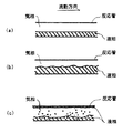
気液分離流を例示して説明すると、層状流(図2(a) 参照)は、水平管内において、重力作用により液相は管底部を流れ、気相は管上部を流れることにより形成され、気液界面がほぼ平滑な面を有する流れをいう。波状流(図2(b) 参照)は、上記層状流において気相流速が増したとき、気液界面に波状を呈する流れをいう。環状流は、管壁に液膜が存在し、管断面中心部に気相が形成される流れ、環状噴霧流(図2(c) 参照)は、この気相部に液滴を含む流れをいう。
【0022】
本発明では、これらのうちでも特に環状流または環状噴霧流が形成されることが好ましい。
なおこのような流動様式の定義については、気液二相流技術ハンドブック「1流動様式」(日本機械学会編1989年発行)などに詳細が記載されている。
【0023】
反応器1には、原料モノマー2および重合触媒3とともに必要に応じて不活性媒体4を供給することができるが、この不活性媒体としては、重合に悪影響を及ぼさないものであれば公知の反応不活性な化合物を広く用いることができる。たとえば不活性媒体としては、炭素数1〜20の飽和炭化水素を用いることができ、具体的にメタン、エタン、プロパン、ブタン、ペンタン、ヘキサン、ヘプタン、オクタン、デカン、ドデカン、テトラデカンなどの脂肪族炭化水素類、シクロペンタン、メチルシクロペンタン、シクロヘキサン、メチルシクロヘキサン、シクロオクタン、シクロヘキセンなどの脂環族炭化水素を用いることもできる。
また不活性媒体として、たとえば窒素、アルゴン、ヘリウムなどの不活性ガスを用いることができる。
【0024】
本発明では、原料モノマーおよび必要に応じて不活性媒体をたとえば加熱器5で加熱することにより加圧状態で反応器1内に供給するが、通常、反応器入口圧力は大気圧〜100kg/cm2・F好ましくは5〜50kg/cm2・Fであることが望ましい。なお反応器入口1aでは、反応器内特に反応器出口1bとの差圧により加圧状態となればよく、たとえば反応器入口圧力が大気圧であっても反応器出口1bが減圧状態であれば相対的に加圧状態で原料モノマーなどを供給することになる。
【0025】
反応器内では、供給された原料モノマーおよび不活性媒体のうちの一部を気相とし、残余を液相として、気相と、液相とを形成させる。
反応器に供給される原料モノマーおよび上記不活性媒体のうち、常圧下での沸点が200℃以下好ましくは150℃以下、特に好ましくは100℃以下のものは、反応器内で気相を形成する場合がある。
【0026】
具体的に反応器内で気相として存在しうる不活性媒体としては、上記窒素などの不活性ガス、および上記飽和炭化水素のうちでも炭素数1〜20の飽和炭化水素が挙げられ、好ましくは炭素数3〜10の飽和炭化水素が挙げられる。
【0027】
気相は、原料モノマーガスのみ、あるいは不活性ガスから形成されてもよく、これらの混合ガスで形成されてもよい。
気相中には、2種以上の原料モノマーガスまたは2種以上の不活性ガスが含まれていてもよい。また気相中には、他のガス状成分たとえば分子量調節剤としての水素などが含まれていてもよい。
【0028】
また液相は、上記原料モノマーおよび上記不活性媒体のうち、気相を形成しない残余の原料モノマーおよび/または不活性媒体から形成される。
上記原料モノマーおよび上記不活性媒体のうち、常圧下での沸点が−150℃以上好ましくは−40℃以上で、かつ350℃以下であるものは、反応器内で液相で存在しうる。
【0029】
具体的に、上記飽和炭化水素のうちでも炭素数1〜20好ましくは3〜10の炭化水素が挙げられる。
液相中には、2種以上の原料モノマーまたは2種以上の不活性溶媒が含まれていてもよい。
【0030】
またこの液相は生成するポリマーを固体(スラリー)として含有していてもよい。
なお反応器内で液相を形成しうる原料モノマーまたは不活性媒体は、気相を形成しうる原料モノマーまたは不活性媒体に対して、体積比で0.00001〜100000好ましくは0.001〜10000の量で反応器内に供給することが望ましい。
【0031】
触媒は、気液固のいずれの状態で供給されてもよい。この触媒成分および供給方法については詳細を後述する。
本発明では、供給された諸成分は、反応器内で上述したような気液分離流または気液固分離流を形成し、反応器内の液相または固液相を、該反応器内の原料モノマーおよび/または不活性媒体ガス(以下搬送ガスともいう)からなる気相によって搬送しながら、原料モノマーの重合を行っている。
【0032】
原料モノマー、触媒および不活性媒体を管型反応器内に供給して上記のような分離流を形成する際には、一般には管内の最もガス線速が遅い部分でのガス線速が、0.5〜500m/sec 、好ましくは1〜300m/sec 、特に好ましくは3〜150m/sec であることが望ましい。
【0033】
ガス線速は、反応器出口1bでのガス流量(体積)について、温度・圧力補正および気液平衡計算を行い、反応器内のガス流量(体積)に換算した後、反応器内をこのガスのみが流通したものとして換算したときのガス流量を、反応器の流れ断面積で除することにより得られる値である。なお反応器出口1bでのガス流量(体積)は、反応器出口1bに気液分離器を接続し、気液分離器のガス排出管から排出されるガス流量を体積流量計で測定して求めることができる。
【0034】
反応器内で上記のような分離流を形成しながら行なわれる重合では、重合圧力が、通常0.1〜1000kg/cm2F、好ましくは1.1〜100kg/cm2Fさらに好ましくは1.5〜80kg/cm2F特に好ましくは1.7〜50kg/cm2Fであることが望ましい。この重合圧力は、反応器入口1aでの圧力と反応器出口1bでの圧力との平均値である。
【0035】
また重合温度は、通常−50〜+300℃好ましくは−20〜+250℃以下特に好ましくは20〜200℃であることが望ましい。
生成したポリマーは、液相中に溶解してまたは液相中に懸濁した状態で上記搬送ガスにより搬送される。
【0036】
なお反応器内液相中の原料モノマーは重合により消費されることにより、また不活性媒体は重合熱で加熱されることにより、反応器出口1bでは、ポリマーのみからなる液相が形成されることがある。
【0037】
反応器出口1bでの液相(ポリマー液)は、通常、ホッパーなどのポリマー分離器6でポリマーと溶媒とを分離した後得られたポリマーを押出機(図示せず)に供給するが、この反応器出口1bでの液相(ポリマー液)は実質的に溶媒を含有していないかまたは極少量しか含有していないので、場合によっては直接押出機に導入することも可能である。
【0038】
液相中の生成ポリマーの濃度は特に限定されないが、たとえば100重量%〜35重量%好ましくは90〜40重量%の高濃度であってもよく、それより低濃度であってもよい。
【0039】
反応器出口1bでは、上記のようにしてポリマーのみからなるか、あるいは原料モノマーまたは不活性媒体にポリマーが溶解または懸濁してなる液相が得られる。
本発明では、反応器出口1bでのこの液相と気相との流量比(液相/気相)(S/G比)を、体積流量比で、0.00001〜100000、好ましくは0.00001〜10000、特に好ましくは0.00001〜1000としている。
【0040】
上記S/G比(体積流量比)は、反応器入口1aにおいて流量計により測定した原料モノマーおよび不活性媒体の全供給量について、反応器内の温度、圧力に基づいてvan der Waals式、virial式などの状態方程式を用いた温度・圧力補正およびRoultの法則、Redlich-Kister式などを用いた気液平衡計算することにより、反応器内での液相体積流量および気相体積流量を求める。得られた液相体積流量にポリマーの体積流量を加重した値をSとし、上記で得られた気相体積流量をGとして、S/G比(体積流量比)を得ることができる。
【0041】
この反応器出口1bでのS/G比は質量流量比であってもよく、質量流量比であるときにはS/G比を、0.00001〜5000、好ましくは0.0001〜500、特に好ましくは0.0001〜50とする。
【0042】
上記S/G比(質量流量比)は、反応器入口1aにおいて流量計により測定した原料モノマーおよび不活性媒体の全供給量について、反応器内の温度、圧力に基づいてvan der Waals式、virial式などの状態方程式を用いた温度・圧力補正およびRoultの法則、Redlich-Kister式などを用いた気液平衡計算することにより、反応器内での液相質量流量および気相質量流量を求める。得られた液相質量流量にポリマーの質量流量を加重した値をSとし、上記で得られた気相質量流量をGとして、S/G比(質量流量比)を得ることができる。
【0043】
反応器内の管長方向単位長さ当たりの圧力損失は、一般に5kg/cm2・m以下、好ましくは2kg/cm2・m以下、特に好ましくは1kg/cm2・m以下であることが望ましい。
【0044】
本発明では、上記のようにして反応器出口1bから得られる液相の粘度は特に限定されず、広範な粘度範囲の重合液を得ることができる。通常、反応器出口1bでの液相粘度(反応器出口温度における)がその上限で100万poise 好ましくは10万poise 特に好ましくは5万poise であるような高粘度ポリマー液(重合液)を得ることができる。またこの液相粘度の下限は特に限定されるものではなく、通常1cp以上、好ましくは10cp以上であればよい。
【0045】
より具体的には、反応器出口1bでの液相粘度すなわち実質的に本発明で製造されるポリマーの粘度(230℃、せん断速度10sec-1の条件下に測定時)は、1×10²〜1×10⁶poiseであることが望ましく、3×10²〜1×10⁶poiseの高粘度も好ましく、1×10³poise以上であっても何ら支障がない。
この粘度は、毛細式流れ特性試験機(東洋精機製作所(株)製)を用いて、溶融ポリマーのずり応力を測定し、測定されたずり応力を粘度に換算することにより求められる。すなわち溶融ポリマーをずり速度を変えながらキャピラリーから押し出した時の応力を測定し、測定された応力をずり速度により除することにより求められる。
【0046】
反応器内に上記のような分離流を形成し、気相流を搬送ガスとして液相(または固液相)を搬送する本発明の重合方法によれば、液相中の生成ポリマー濃度が高く、高粘度となっても、該高粘度液を反応器内を搬送ガスで容易に搬送することができ、搬送ガス以外の搬送動力を特に必要としない。また本発明では、攪拌設備も必要とせず、動力エネルギ面において優れている。
【0047】
上記重合で用いられる管型反応器は、反応器内に上記のような分離流を形成しうるものであればその断面形状、大きさなどについては特に限定されないが、通常管内径が1〜50cm程度、管長が10〜500m程度である。管径の異なる反応器を2以上接続してもよい。また管型反応器は、直線状であっても曲線部を有していてもよい。上記管型反応器は、傾斜して設置されてもよいが、通常水平に設置される。
【0048】
上記のような管型反応器を用いて行なわれる重合は、エネルギ効率に優れており、反応熱は容易に除去することができ、反応によっては自然放熱だけで冷却することも可能であるが、反応器の外周部には、熱交換設備を設けることができ、除熱または加熱を必要とする反応に応じて、該設備に熱媒体を流通させて反応熱の除去あるいは反応系の加熱を行なうことが望ましい。
【0049】
このような熱交換設備として、たとえばジャケットを設けることができ、反応管の途中での反応温度の変更が可能なように、管型反応器の外周部に必要に応じて複数に分割して設けることができる。
【0050】
重合熱の除去のために気相部あるいは重合液を外部熱交換器で冷却して反応系に循環させてもよい。
本発明では、反応管の管長方向の任意の場所にモノマー供給口などを適宜設けて、共重合モノマーなどを供給することができる。このように反応管途中でモノマーを供給すると、種々の共重合成分を有するポリマーを単独の反応器で製造することができる。
【0051】
上記のような重合方法では、種々の重合性モノマーを反応させることができ、目的ポリマーに応じた原料モノマーおよび触媒を特に限定されることなく用いることができる。
【0052】
本発明では、原料モノマーとしてたとえばオレフィンを用いることができる。オレフィン重合では、具体的に、エチレン、プロピレン、1-ブテン、1-ペンテン、1-ヘキセン、4-メチル-1-ペンテン、1-オクテン、1-デセン、1-ドデセン、ノルボルネン、テトラシクロドデセン、メチルテトラシクロドデセンなどの炭素数2〜20の直鎖状、分岐状、環状オレフィン類を単独重合あるいは共重合させることができる。またオレフィン類と非共役ジエンとを共重合させてもよく、たとえば5-エチリデン-2-ノルボルネン、5-プロピリデン-2-ノルボルネン、ジシクロペンタジエン、5-ビニル-2-ノルボルネンなどの環状ジエン、1,4-ヘキサジエン、5-メチル-1,5-ヘプタジエン、6-メチル-1,5-ヘプタジエン、6-メチル-1,7-オクタジエン、7-メチル-1,6-オクタジエンなどの鎖状非共役ジエンを共重合させることができる。
【0053】
さらにオレフィンと、たとえばスチレンなどのCR2=CR−Phで示されるビニリデン芳香族モノマー類とを共重合させてもよい。(Rはそれぞれ独立に水素またはメチルであり、Phはフェニル基またはp-アルキル置換フェニル基であり、これらはハロゲン置換基を有していてもよい。)
本発明では、上記スチレンなどのビニリデン芳香族モノマー類を重合させてもよい。
また本発明で用いられる触媒は、重合に供されるものであればいずれでもよいが、触媒の一例として上記のようなオレフィン類を重合させる際には、たとえば下記のような遷移金属触媒成分と、助触媒成分とからなるオレフィン重合用触媒が好ましく用いられる。
【0054】
遷移金属触媒成分としては、周期律表第IVB族から選ばれる遷移金属化合物[A]が用いられ、この遷移金属化合物は、たとえば下記式(i) で示される。
MLx …(i)
式中、MはZr,Ti,Hf,V,Nb,TaおよびCrから選ばれる遷移金属である。Lは遷移金属に配位する配位子であり、水素原子、ハロゲン原子、酸素原子、置換基を有していてもよい炭素数1〜30の炭化水素基、アルコキシ基、アリーロキシ基、トリアルキルシリル基、SO3R基(ここで、Rはハロゲンなどの置換基を有していてもよい炭素数1〜8の炭化水素基)である。xは遷移金属の原子価である。
【0055】
ハロゲンとしてはフッ素、塩素、臭素、ヨウ素などが挙げられる。
炭素数1〜30の炭化水素基としては、具体的に、
メチル基、エチル基、プロピル基、イソプロピル基、ブチル基などのアルキル基、
シクロペンチル基、シクロヘキシル基などのシクロアルキル基、
フェニル基、トリル基、シクロペンタジェニル基などのアリール基、
ベンジル基、ネオフィル基などアラルキル基などが挙げられる。
【0056】
シクロアルキル基、アリール基、アラルキル基は、その一部がハロゲン原子、アルキル基、トリアルキルシリル基などで置換されていてもよい。
また炭化水素基が、シクロアルキル基、アリール基、アラルキル基であり、かつ複数配位している場合には、エチレン、プロピレンなどのアルキレン基、イソプロピリデン、ジフェニルメチレン基などの置換アルキレン基、シリレン基またはジメチルシリレン、ジフェニルシリレン、メチルフェニルシリレン基などの置換シリレン基などを介して結合されていてもよい。
【0057】
アルコキシ基としては、メトキシ基、エトキシ基、ブトキシ基などが挙げられ、アリーロキシ基としては、フェノキシ基などが挙げられる。
これら化合物を2種以上組み合わせて用いてもよく、また炭化水素あるいはハロゲン化炭化水素に希釈して用いてもよい。
【0058】
上記のような遷移金属化合物は固体状で重合系に供することができ、たとえば上記遷移金属化合物を粒子状担体化合物と接触させて、粒子状担体化合物とともに用いることができる。担体化合物としては、具体的に、SiO2、Al2O3、B2O3,MgO、ZrO2、CaO、TiO2、ZnO、Zn2O、SnO2、BaO、MgCl2、NaClなどの無機化合物、ポリエチレン、ポリプロピレン、ポリ-1-ブテン、ポリ4-メチル-1-ペンテン、スチレン−ジビニルベンゼン共重合体などの樹脂を用いることができる。担体は2種以上組み合わせて用いることもできる。なおこの粒子状担体化合物は、遷移金属化合物との接触過程において粒子状に形成されてもよい。これらのうちでも、とくにMgCl2、SiO2が好ましい。
【0059】
またオレフィン重合用触媒を形成する助触媒成分としては、
[B]有機アルミニウム化合物、有機アルミニウムハロゲン化合物、アルミニウムハロゲン化合物、有機ホウ素化合物、有機ホウ素オキシ化合物、有機ホウ素ハロゲン化合物、ホウ素ハロゲン化合物および有機アルミニウムオキシ化合物から選ばれる化合物が用いられる。
【0060】
このような化合物群[B]は、上記のうち有機アルミニウムオキシ化合物を除いては具体的に下記式(ii)で示される。
BRx …(ii)
式中Bは、アルミニウム原子あるいはホウ素原子であり、xはアルミニウムまたはホウ素の原子価である。
【0061】
式(ii)で示される化合物が、有機アルミニウム化合物あるいは有機ホウ素化合物の場合には、Rは炭素数1〜30のアルキル基であり、
アルミニウムハロゲン化合物あるいはホウ素ハロゲン化合物の場合には、Rはハロゲン原子であり、
有機アルミニウムハロゲン化物あるいは有機ホウ素ハロゲン化物の場合には、Rは炭素数1〜30のアルキル基とハロゲン原子との両者である。
【0062】
上記ハロゲンとしてはフッ素、塩素、臭素、ヨウ素などが挙げられ、炭素数1〜30のアルキル基としては、具体的にはメチル基、エチル基、プロピル基、イソプロピル基、ブチル基、イソブチル基などが挙げられる。
また有機アルミニウムオキシ化合物は、具体的には下記式(iii) または(iv)で示される。
【0063】
【化1】

これら式において、Rはメチル基、エチル基、プロピル基、ブチル基などの炭化水素基であり、mは2以上、好ましくは5〜40の整数である。
上記アルミノキサンは、式(OAl(R1))で示されるアルキルオキシアルミニウム単位(R1は上記Rと同様の基)と、式(OAl(R2))で示されるアルキルオキシアルミニウム単位(R2はR1と異なる上記Rと同様の基)との混合アルキルオキシアルミニウム単位から形成されていてもよい。
【0065】
またアルキルオキシアルミニウム単位中のRは、一部であれば、ハロゲンまたは水素アルコキシ基、アリーロキシ基、水酸基であってもよい。
これら化合物を2種以上組み合わせて用いてもよく、また炭化水素あるいはハロゲン化炭化水素に希釈して用いてもよい。
【0066】
上記のような遷移金属化合物触媒成分と助触媒とを適宜組合わせたオレフィン重合用触媒としては、具体的に、チーグラー系触媒、メタロセン系触媒、バナジウム系触媒などが挙げられる。
【0067】
オレフィン重合用触媒は、上記のような遷移金属触媒成分[A]と助触媒成分[B]とともに必要に応じて電子供与体を含有していてもよい。電子供与体としては、たとえばエーテル化合物、カルボニル化合物、アルコキシ化合物などを用いることができる。
【0068】
本発明では、上記のような触媒成分にオレフィンを予備重合させて、予備重合触媒を形成して用いることもできる。具体的には、上記のような遷移金属触媒成分と、助触媒成分とからなる触媒に、該遷移金属触媒成分1g当たり50〜5000g、好ましくは300〜3000gの量でオレフィンを予備重合させた予備重合触媒を用いることが好ましい。
予備重合される遷移金属触媒成分は、通常上記したような粒子状担体化合物に担持されていることが好ましい。予備重合時には、必要に応じて電子供与体を用いることもできる。
【0069】
予備重合されるオレフィンとしては、前述した重合原料(本重合)オレフィンと同様のものを挙げることができ、予備重合オレフィンは本重合オレフィンと同一であっても異なっていてもよい。また2種以上のオレフィンを予備重合させることもできる。
【0070】
予備重合は、上記のような量でオレフィンを予備重合させること以外、特にその方法は限定されず、公知の予備重合方法を広く利用して行うことができる。
たとえば予備重合はオレフィンが液状となる状態で行うこともできるし、また不活性溶媒の共存下で行うこともでき、さらには気相条件下で行うことも可能である。このうち不活性溶媒の共存下、該不活性溶媒に予備重合オレフィンおよび各触媒成分を加え、比較的温和な条件下で予備重合を行うことが好ましい。この際、生成した予備重合体が重合媒体に溶解する条件下に行なってもよいし、溶解しない条件下に行なってもよいが、溶解しない条件下に行うことが好ましい。
予備重合は、通常約−20〜+100℃好ましくは約−20〜+80℃さらに好ましくは−10〜+60℃で行なうことが望ましい。
また予備重合は、バッチ式、半連続式、連続式のいずれにおいても行うことができる。
【0071】
予備重合における触媒成分の濃度は、触媒成分の種類によっても異なるが、遷移金属触媒成分の濃度は、重合容積1リットル当り、遷移金属原子換算で、通常約0.001〜5000ミリモル好ましくは約0.01〜1000ミリモル特に好ましくは0.1〜500ミリモルであることが望ましい。
助触媒成分は、遷移金属触媒成分中の遷移金属原子1モル当り、通常約0.1〜1000モル好ましくは約0.5〜500モル特に好ましくは1〜100モルの量で用いることができる。
予備重合時には、水素などの分子量調節剤を用いることもできる。
予備重合触媒が懸濁状態で得られる場合には、予備重合触媒を懸濁状態のままで反応器内に供給することもできるし、懸濁液から予備重合触媒を分離して供給することもできる。
【0072】
上記のような予備重合触媒の粒径は、10μm以上、好ましくは50〜500μmであることが望ましい。
本発明では、反応器内に予備重合触媒を供給する際には、予備重合触媒に加えて助触媒成分を供給することができる。またこの助触媒成分を供給しなくてもよいこともある。
【0073】
前述したように本発明では、反応器内の液相を、該反応器内の気相流によって搬送しながら原料モノマーの重合を行っており、この際上記のような量でオレフィンが予備重合された触媒を用いると、反応器内に供給された触媒を有効に利用することができる。
なお触媒粒径が小さいと、反応器内に供給された触媒が気相流によりショートパスして触媒能力を充分に発現できないことがある。
【0074】
また本発明では、上記のような遷移金属触媒成分または予備重合触媒と、助触媒成分とからなるオレフィン重合用触媒を反応器内に供給するに際して、該助触媒成分を予め不活性溶媒と混合して不活性溶媒とともに反応器内に供給することが好ましい。
【0075】
この助触媒成分と混合される不活性溶媒としては、前記反応管内に供給される不活性溶媒と同様のものが挙げられ、これらは同一であることが好ましい。
助触媒成分と不活性溶媒との予備混合は、助触媒成分と不活性溶媒とが均一に混合されるように行われ、具体的に不活性溶媒に助触媒成分を添加して、5〜60℃の温度で、0.5〜24時間攪拌して行われる。この予備混合時には、不活性溶媒は助触媒成分1gに対して、250〜2.5×10⁷mlの量で用いられることが望ましい。
この予備混合は、バッチ式あるいは連続式いずれで行ってもよい。
【0076】
このように助触媒成分を不活性溶媒と予備混合して反応器内に供給すると、助触媒成分が充分に反応系に分散するので、反応器内に供給された助触媒成分を有効的に利用することができる。このため反応に必要な最小限の量(計算値)にほぼ相当するような量を反応器内に供給すればよくなる。
なお助触媒成分を過剰量で反応器内に供給すると、遷移金属触媒成分の活性低下を招いて、遷移金属当たりの重合活性が低下することもある。
【0077】
本発明では、生成するポリオレフィンの分子量を重合温度などの重合条件、あるいは分子量調節剤(水素など)の使用量を変更することにより調節することができる。
本発明により、たとえばエチレンと炭素数6程度以上のα−オレフィンとを共重合させたときには、分子量分布の広いエチレン・α−オレフィンエラストマーを製造することができる。
【0078】
上記のような本発明に係る重合方法は、特に密度が、0.800〜1.100g/cm3 、好ましくは0.820〜1.080g/cm3 、さらに好ましくは0.830〜1.050g/cm3 であるポリマーの製造に適している。
また本発明で得られるポリマーの弾性率は、1〜1×10⁴ MPa、好ましくは2〜5×10³ MPa、さらに好ましくは2〜3×10³ MPaであることが望ましい。
このポリマーの弾性率はいわゆる曲げ弾性率と称されるものであって、ASTM C790に準拠して、厚さ2mmの試験片を用いて、スパン間32mm、曲げ速度5mm/分の条件下に測定されるものである。
【0079】
【発明の効果】
上記のように管型反応器内に気液分離流または気液固分離流を形成しながら重合を行なう本発明の重合方法によれば、特に優れた熱効率で重合を行なうことができ、たとえば発熱量の大きい反応であっても反応器ジャケットのみで除熱することも可能である。
【0080】
また反応器内の流動方向に連続的な気相を有する分離流とし、該気相流により液相を搬送させているので、生成ポリマーが溶解して液相が高粘度溶液となっても、反応器内で管詰まりしにくく、搬送ガスだけで反応管内を搬送させることができる。したがって循環ポンプなどの搬送動力を別途付設する必要がなく、また高粘度溶液を攪拌する必要もないので、少ない動力エネルギで重合を行なうことができる。
【0081】
さらに反応器出口1bでの液相(ポリマー液)は、実質的に溶媒を含有していないかまたは極少量しか含有しておらず、ポリマーの乾燥設備を大幅に簡略化することができ、場合によっては直接押出機に導入することも可能であり、溶媒リサイクル工程を簡略化することもできる。
【0082】
上記のように本発明では、簡便な反応装置を用いるとともに、大型攪拌機、乾燥設備、高圧圧縮設備などの特に大規模な付帯設備を必要とせず、低い装置コストで上記重合を行うことができるとともに、製造されるポリマーの粘度、融点などの制約が少ない。
【0083】
また管長方向に対して任意の温度制御が容易に行うことができ、さらに管長方向に対して任意の位置でコモノマーを供給することができるので、単独の管型反応器により種々の物性を有するポリマーを製造することが可能である。
【0084】
【実施例】
次に本発明を実施例により具体的に説明するが、本発明はこれら実施例に限定されるものではない。
なお実施例において、S/G比(体積流量比)は下記のように求めた。
反応器にフィードした原材料(モノマー、溶媒を含む)の量、組成をもとに、反応器内の温度、圧力状態における気液平衡を公知のRedlich-Kister状態式により計算することで、原材料の液/ガス体積流量比(S/G比)を算出した。
液流量については、反応器出口1bからのポリエチレンの流量を加重した後、この値について先のガス流量で除することにより体積流量比によるS/G比とした。
また以下の実施例で得られたポリエチレンのMIは、ASTM D1238に準拠して、190℃、2.16kg荷重下で測定した値である。
【0085】
【実施例1】
管型反応器(1/2B×40mの鋼管)内に、原料モノマー、チタン系チーグラー系予備重合触媒(遷移金属化合物触媒成分1gあたり2000gのエチレンを予備重合した触媒)、アルキルアルミニウムおよびn-デカンを供給して、下記の条件下に原料モノマーであるエチレンと炭素数6のα−オレフィン(4-メチル-1-ペンテン)とを共重合させた。
【0086】
エチレン/α−オレフィン/n-デカン=83/11/6(モル比)
ガス線速(反応器入口)=30m/sec 、
反応温度=170℃、
反応圧力=16kg/cm2・F
S/G比(体積流量比)=1.3×10-3
S/G比(質量流量比)=0.05
液相(ポリマー液)濃度(反応器出口)=80重量%
液相(ポリマー液)粘度(反応器出口)=1000poise
上記重合では、反応管中に気液分離流が形成されていた。
【0087】
上記の重合により、反応器出口において、予備重合触媒中の遷移金属化合物触媒成分1gあたりの重合量が190000gであり、品質の良好なポリエチレンが0.5kg/hrの流量で得られた。
得られたポリエチレンのMIは5g/10分であり、密度は0.95g/cm3 であった。
【0088】
上記重合では、反応器ジャケットによる冷却のみで反応熱を除去することができた。
また生成したポリエチレンから重合溶媒を除去するために反応器とは別に装置設備を用いる必要はなかった。
【0089】
【実施例2】
重合条件を下記のように変えた以外は実施例1と同様にして重合を行なった。
エチレン/α−オレフィン/n-デカン=71/22/6(モル比)
ガス線速(反応器入口)=5m/sec 、
反応温度=155℃、
反応圧力=11kg/cm2・F
S/G比(体積流量比)=1.0×10-4
S/G比(質量流量比)=0.005
液相(ポリマー液)濃度(反応器出口)=80重量%
液相(ポリマー液)粘度(反応器出口)=100poise
上記重合では、反応管中に気液分離流が形成されていた。
【0090】
上記の重合により、反応器出口において、遷移金属化合物触媒成分1gあたりの重合量が400000gであり、品質の良好なポリエチレンが0.1kg/hrの流量で得られた。
得られたポリエチレンのMIは35g/10分であり、密度は0.89g/cm3 であった。
【0091】
上記重合では、反応器ジャケットによる冷却のみで反応熱を除去することができた。
また生成したポリエチレンから重合溶媒を除去するために反応器とは別に装置設備を用いる必要はなかった。
【0092】
【実施例3】
管型反応器(1/2B×25m+5/6B×15mの鋼管)内に、原料モノマー、実施例1と同様の予備重合触媒、アルキルアルミニウムおよびn-デカンを供給して、下記の条件下に原料モノマーであるエチレンを重合させた。
【0093】
エチレン/n-デカン=81/19(モル比)
ガス線速(反応器入口)=15m/sec 、
反応温度=160℃、
反応圧力=8kg/cm2・F
S/G比(体積流量比)=3.5×10-5
S/G比(質量流量比)=0.0035
液相(ポリマー液)濃度(反応器出口)=80重量%
液相(ポリマー液)粘度(反応器出口)=500poise
【0094】
上記重合では、反応管中に気液分離流が形成されていた。
上記の重合により、反応器出口において、遷移金属化合物触媒成分1gあたりの重合量が146000gのポリエチレンが得られた。
得られたポリエチレンのMIは1.0g/10分であり、密度は0.96g/cm3 であった。
【0095】
上記重合では、反応器ジャケットによる冷却のみで反応熱を除去することができた。
また生成したポリエチレンから重合溶媒を除去するために反応器とは別に装置設備を用いる必要はなかった。
【0096】
【実施例4】
実施例3において、アルキルアルミニウムと、該アルキルアルミニウム1mgに対して、90mlの量のn-デカンとを、室温で1時間(滞留時間)で予備混合して反応器に供給した以外は、実施例3と同様にしてエチレンを重合させた。
すなわち管型反応器(1/2B×25m+5/6B×15mの鋼管)内に、原料モノマー、実施例1と同様の予備重合触媒、およびアルキルアルミニウムとn-デカンとの予備混合物を供給して、下記の条件下に原料モノマーであるエチレンを重合させた。
【0097】
エチレン/n-デカン=81/19(モル比)
ガス線速(反応器入口)=15m/sec 、
反応温度=160℃、
反応圧力=8kg/cm2・F
S/G比(体積流量比)=3.5×10-5
S/G比(質量流量比)=0.0035
液相(ポリマー液)濃度(反応器出口)=80重量%
液相(ポリマー液)粘度(反応器出口)=500poise
上記重合では、反応管中に気液分離流が形成されていた。
【0098】
上記の重合により、反応器出口において、遷移金属化合物触媒成分1gあたりの重合量が293000gでかつ品質の良好なポリエチレンが、0.8kg/hrの流量で得られた。
得られたポリエチレンのMIは2g/10分であり、密度は0.96g/cm3 であった。
【0099】
上記重合では、反応器ジャケットによる冷却のみで反応熱を除去することができた。
また生成したポリエチレンから重合溶媒を除去するために反応器とは別に装置設備を用いる必要はなかった。
【0100】
【比較例1】
従来の液相流のチューブ型(管型)反応器では、製品品質を維持するために重合液の混合性を確保する必要がありポリマー濃度を20重量%以下とした。
そのため、反応器の下流には重合溶媒を除去するための設備が必要となった。
【図面の簡単な説明】
【図1】本発明に係る重合方法の態様例を模式的に示す。
【図2】本発明において、反応器内で形成される気液分離流の流動様式を示す。[0001]
TECHNICAL FIELD OF THE INVENTION
The present invention relates to a polymerization method using a separation flow in which a raw material monomer is polymerized while forming a gas-liquid separation flow or a gas-liquid solid separation flow in a tubular reactor.
[0002]
TECHNICAL BACKGROUND OF THE INVENTION
Conventionally, tank reactors, tube reactors, tower reactors, fluidized bed reactors, special reactors and the like are known as reaction apparatuses.
Each of these reactors is selected according to the reaction form, physical properties of the product to be produced, etc., but when the reaction is a polymerization reaction, a tank reactor or a fluidized bed reactor is generally used as the polymerization apparatus. It is used.
[0003]
When a tank reactor is used as a polymerization apparatus, liquid phase polymerization such as solution (homogeneous) polymerization and slurry polymerization is usually performed using a solvent. In such liquid phase polymerization, a relatively high quality polymer is produced. There is an advantage that there are few restrictions on the physical properties and operating conditions of the polymer obtained and produced.
[0004]
However, in the liquid phase polymerization using the tank reactor as described above, the polymer to be produced is dissolved or suspended in a polymerization solvent with stirring to form a polymer solution (polymer solution or slurry) of the produced polymer. As the polymerization solution increases in viscosity, the stirring power also increases. In particular, when a high-viscosity (polymer) polymerization solution is produced industrially, a huge stirring facility is required, and the stirring energy tends to be enormous.
[0005]
Moreover, in said liquid phase polymerization, it is necessary to isolate | separate a polymer and a solvent after superposition | polymerization, the installation and energy for that are required, and also the refinement | purification equipment of a solvent may be needed.
[0006]
When a fluidized bed reactor is used as a polymerization apparatus, the polymerization is performed while fluidizing a solid (catalyst, product polymer) with a gas medium to form a fluidized bed, so that removal of the medium is generally unnecessary and inexpensive. A polymer can be produced. On the other hand, it is necessary to control the gas linear velocity to the extent that the fluidized bed can be maintained. In the polymerization with a large reaction heat, the polymerization is limited by the amount of heat exchange, or the fluidized bed cannot be formed when the polymer melting point is low. Yes, the operating range is often limited.
[0007]
In the tank reactor or fluidized bed reactor as described above, the physical properties of the polymer are controlled by inserting additional raw materials at arbitrary positions in the reactor according to the degree of polymerization.BIn order to obtain a polymer having desired physical properties, a plurality of reactors are often prepared.
[0008]
Polymerization using a tubular reactor (tube reactor) as a polymerization apparatus is also known. For example, a monomer gas is compressed into a reaction tube at a high pressure and supplied as a supercritical fluid. High-pressure polymerization reaction (a method for producing high-pressure polyethylene), or homogeneous polymerization or slurry polymerization using a liquid medium is known. It is also known that this tube reactor is used as an apparatus for adjusting the physical properties of a polymer in the subsequent step of the manufacturing process of the tank reactor or fluidized bed reactor.
[0009]
However, in the conventional polymerization method using a tube reactor, the viscosity (or concentration) of the polymerization solution that can be transported in the reaction tube is easily limited by the capacity of the circulation pump and the like, and it is not possible to obtain a high viscosity (high concentration) polymerization solution. Have difficulty.
[0010]
When a high-pressure monomer supercritical fluid is introduced into a tube reactor as described above to perform a high-pressure reaction, a huge and expensive compression device for compressing the monomer, a device for maintaining high pressure, safety Equipment is required. In the reaction using this supercritical fluid (liquid), the reaction temperature is often kept low, and the heat of reaction is difficult to remove despite the large heat transfer area of the reactor.
[0011]
Furthermore, in the case of liquid phase polymerization, it is necessary to separate the polymer produced after polymerization from the solvent as described above.
In view of the prior art as described above, the present inventor can perform polymerization with excellent thermal efficiency and low kinetic energy, and can produce a wide variety of polymers with less restrictions such as viscosity and melting point of the produced polymer. As a result of research on a polymerization apparatus and a polymerization method that can be manufactured and that can simplify the process of removing the solvent from the polymer after the polymerization, a tubular reactor is supplied with a raw material monomer, a polymerization catalyst, and if necessary. An inert medium is supplied in a pressurized state so that a part of the raw material monomer and the inert medium is in a gas phase and the remainder is in a liquid phase, and the gas phase and liquid phase (containing a solid are contained in the reactor). And a gas-liquid separation flow or a gas-liquid solid separation flow having a continuous gas phase in the flow direction in the reactor is formed, and the liquid phase in the reactor is By gas phase flow in the vessel Polymerization of the raw material monomer while transporting, and a polymerization method by a separated flow in which the flow rate ratio between the liquid phase and the gas phase at the outlet of the reactor (liquid phase / gas phase) is 0.0001 to 100,000 in volume flow rate ratio is The inventors have found that the above characteristics are satisfied, and have completed the present invention.
[0012]
It should be noted that the gas-liquid two-phase or gas-solid-liquid three-phase fluid introduced into the pipe may form a separated flow in the literature (for example, the gas-liquid two-phase flow technology handbook “1 flow mode”; However, it was not known to conduct a polymerization reaction in a tube in which such a separated flow was formed.
[0013]
OBJECT OF THE INVENTION
An object of the present invention is to provide a polymerization method capable of performing polymerization with excellent thermal efficiency and low kinetic energy by a simple reaction apparatus, and having less restrictions on the viscosity and melting point of the produced polymer. Yes.
[0014]
SUMMARY OF THE INVENTION
In the polymerization method according to the present invention,
To the tubular reactor, feed the raw material monomer, the polymerization catalyst and, if necessary, an inert medium under pressure,
A part of the raw material monomer and the inert medium supplied into the reactor is made into a gas phase and the remainder is made into a liquid phase, and a gas phase comprising the raw material monomer and / or an inert medium gas in the reactor. And a liquid phase comprising raw material monomers and / or an inert solvent (this liquid phase may contain the produced polymer as a solid), and a continuous gas phase in the flow direction in the reactor. Forming a gas-liquid separation flow or gas-liquid solid separation flow having
While the liquid phase in the reactor is conveyed by the gas phase flow in the reactor, the polymerization of the raw material monomers is performed.Polymerization temperature 155 to 200 ° C., polymerization pressure 0.1 to 16 kg / cm 2 In FAt the reactor outlet
The flow rate ratio between the liquid phase and the gas phase (liquid phase / gas phase) is 0.0001 to 100,000 in terms of volume flow rate.
It is characterized by doing.
[0015]
The separation flow is specifically a laminar flow, a wave flow, an annular flow or an annular spray flow, and among these, an annular flow or an annular spray flow is preferable.
If a heat exchange facility is provided on the outer periphery of the tubular reactor and a heat medium is passed through the heat exchange facility, the temperature in the reactor can be easily controlled.
In the present invention, an olefin can be used as a raw material monomer.
[0016]
In the present invention, when the olefin is polymerized in this way,Periodic Table Group 4An olefin polymerization catalyst comprising a transition metal catalyst component selected from the above and a cocatalyst component can be used, and in particular, a prepolymerized catalyst obtained by prepolymerizing an olefin in an amount of 50 to 5000 g per 1 g of the transition metal catalyst component. It is preferable to use it.
This prepolymerized transition metal catalyst component is usually supported on a particulate carrier compound, and the particulate carrier compound is MgCl.2Or SiO2It is preferable that The particle size of such a prepolymerized catalyst is desirably 10 μm or more.
In the present invention, when the transition metal catalyst component or the prepolymerized catalyst as described above and the promoter component are fed into the reactor, the promoter component is mixed with an inert solvent in advance. At the same time, it is preferably supplied into the reactor.
[0017]
DETAILED DESCRIPTION OF THE INVENTION
The polymerization method according to the present invention will be specifically described below.
In the present invention, the term “polymerization” may be used to mean not only homopolymerization but also copolymerization, and the term “polymer” refers to not only a homopolymer but also a copolymer. May be used in an inclusive sense.
[0018]
FIG. 1 schematically shows a polymerization method according to the present invention.
In the present invention, the
A part of the raw material monomer and the inert medium supplied into the
The raw material monomer is polymerized while the liquid phase in the
[0019]
First, the separated flow will be described.
In the present specification, the separated flow has a gas phase flow in which a gas-liquid, gas-solid or gas-liquid solid phase flow in a tubular reactor (reactor) is substantially continuous in the flow direction. It means a flow, and the liquid phase, solid phase or solid-liquid phase may be continuous flow or discontinuous flow.
[0020]
In the present invention, among these separated flows, a gas-liquid separated flow and a gas-liquid solid separated flow are preferable.
Specific examples of such a separated flow include a laminar flow, a wavy flow, an annular flow, and an annular spray flow.
[0021]
Explaining the gas-liquid separation flow by way of example, a laminar flow (see FIG. 2 (a)) is formed by a liquid phase flowing through the bottom of the tube and a gas phase flowing through the top of the tube in a horizontal tube, A gas-liquid interface is a flow having a substantially smooth surface. The wavy flow (see FIG. 2 (b)) refers to a flow that exhibits a wavy shape at the gas-liquid interface when the gas phase flow velocity increases in the laminar flow. An annular flow is a flow in which a liquid film exists on the tube wall and a gas phase is formed at the center of the cross section of the tube. An annular spray flow (see FIG. 2 (c)) is a flow containing droplets in the gas phase portion. Say.
[0022]
In the present invention, it is particularly preferable that an annular flow or an annular spray flow is formed among them.
The definition of such a flow mode is described in detail in the gas-liquid two-phase flow technology handbook “1 flow mode” (edited by the Japan Society of Mechanical Engineers in 1989).
[0023]
An inert medium 4 can be supplied to the
As the inert medium, for example, an inert gas such as nitrogen, argon, or helium can be used.
[0024]
In the present invention, the raw material monomer and, if necessary, the inert medium are supplied into the
[0025]
In the reactor, a part of the supplied raw material monomer and the inert medium is a gas phase, and the remainder is a liquid phase, and a gas phase and a liquid phase are formed.
Among the raw material monomers supplied to the reactor and the above inert medium, those having a boiling point under atmospheric pressure of 200 ° C. or lower, preferably 150 ° C. or lower, particularly preferably 100 ° C. or lower form a gas phase in the reactor. There is a case.
[0026]
Specific examples of the inert medium that may exist as a gas phase in the reactor include inert gases such as nitrogen and saturated hydrocarbons having 1 to 20 carbon atoms among the saturated hydrocarbons. C3-C10 saturated hydrocarbon is mentioned.
[0027]
The gas phase may be formed of only the raw material monomer gas or an inert gas, or may be formed of a mixed gas thereof.
The gas phase may contain two or more raw material monomer gases or two or more inert gases. The gas phase may contain other gaseous components such as hydrogen as a molecular weight regulator.
[0028]
The liquid phase is formed from the remaining raw material monomers and / or inert medium that do not form a gas phase among the raw material monomers and the inert medium.
Among the raw material monomers and the inert medium, those having a boiling point under normal pressure of −150 ° C. or more, preferably −40 ° C. or more and 350 ° C. or less may exist in a liquid phase in the reactor.
[0029]
Specific examples of the saturated hydrocarbon include hydrocarbons having 1 to 20 carbon atoms, preferably 3 to 10 carbon atoms.
In the liquid phase, two or more kinds of raw material monomers or two or more kinds of inert solvents may be contained.
[0030]
Moreover, this liquid phase may contain the polymer to produce | generate as solid (slurry).
The raw material monomer or inert medium capable of forming a liquid phase in the reactor is in a volume ratio of 0.0001 to 100,000, preferably 0.001 to 10,000, relative to the raw material monomer or inert medium capable of forming a gas phase. It is desirable to feed into the reactor in an amount of
[0031]
The catalyst may be supplied in any state of gas and liquid. Details of the catalyst component and the supply method will be described later.
In the present invention, the supplied components form a gas-liquid separation stream or a gas-liquid solid separation stream as described above in the reactor, and the liquid phase or solid-liquid phase in the reactor is converted into the reactor. The raw material monomer is polymerized while being conveyed by a gas phase composed of the raw material monomer and / or an inert medium gas (hereinafter also referred to as a carrier gas).
[0032]
When a raw material monomer, a catalyst and an inert medium are supplied into a tubular reactor to form a separated flow as described above, the gas linear velocity at the slowest gas linear velocity in the tube is generally 0. It is desirable that the viscosity is from 0.5 to 500 m / sec, preferably from 1 to 300 m / sec, particularly preferably from 3 to 150 m / sec.
[0033]
As for the gas linear velocity, the gas flow rate (volume) at the reactor outlet 1b is subjected to temperature / pressure correction and gas-liquid equilibrium calculation, converted into the gas flow rate (volume) in the reactor, and then the gas flow in the reactor. It is a value obtained by dividing the gas flow rate when it is converted as if only circulated by the cross-sectional area of the flow of the reactor. The gas flow rate (volume) at the reactor outlet 1b is obtained by connecting a gas-liquid separator to the reactor outlet 1b and measuring the gas flow rate discharged from the gas discharge pipe of the gas-liquid separator with a volume flow meter. be able to.
[0034]
In the polymerization carried out while forming the above separated flow in the reactor, the polymerization pressure is usually 0.1 to 1000 kg / cm.2F, preferably 1.1-100 kg / cm2F More preferably 1.5-80 kg / cm2F Particularly preferably 1.7 to 50 kg / cm2F is desirable. This polymerization pressure is an average value of the pressure at the reactor inlet 1a and the pressure at the reactor outlet 1b.
[0035]
The polymerization temperature is usually −50 to + 300 ° C., preferably −20 to + 250 ° C., particularly preferably 20 to 200 ° C.
The produced polymer is transported by the transport gas in a state where it is dissolved in the liquid phase or suspended in the liquid phase.
[0036]
The raw material monomer in the liquid phase in the reactor is consumed by the polymerization, and the inert medium is heated by the polymerization heat, so that a liquid phase consisting only of the polymer is formed at the reactor outlet 1b. There is.
[0037]
The liquid phase (polymer liquid) at the outlet 1b of the reactor is usually supplied to an extruder (not shown) with the polymer obtained after separating the polymer and the solvent with a polymer separator 6 such as a hopper. Since the liquid phase (polymer liquid) at the reactor outlet 1b contains substantially no solvent or only a very small amount, it can be directly introduced into the extruder in some cases.
[0038]
The concentration of the produced polymer in the liquid phase is not particularly limited, but may be, for example, a high concentration of 100% to 35% by weight, preferably 90 to 40% by weight, or a lower concentration.
[0039]
At the reactor outlet 1b, a liquid phase consisting of the polymer only as described above, or a polymer dissolved or suspended in the raw material monomer or inert medium is obtained.
In the present invention, the flow rate ratio (liquid phase / gas phase) (S / G ratio) of the liquid phase to the gas phase at the outlet 1b of the reactor is 0.0001 to 100,000, preferably 0.00. It is set to 00001 to 10000, particularly preferably 0.0001 to 1000.
[0040]
The S / G ratio (volume flow rate ratio) is calculated based on the van der Waals equation, virial based on the temperature and pressure in the reactor, with respect to the total supply amount of the raw material monomer and the inert medium measured by the flow meter at the reactor inlet 1a. The liquid phase volume flow rate and the gas phase volume flow rate in the reactor are obtained by temperature / pressure correction using the equation of state such as the equation, and vapor-liquid equilibrium calculation using the Law of Roult, the Redlich-Kister equation, and the like. The value obtained by weighting the volume flow rate of the polymer to the obtained liquid phase volume flow rate is S, and the gas phase volume flow rate obtained above is G, and the S / G ratio (volume flow rate ratio) can be obtained.
[0041]
The S / G ratio at the reactor outlet 1b may be a mass flow ratio, and when it is a mass flow ratio, the S / G ratio is 0.0001 to 5000, preferably 0.0001 to 500, particularly preferably. Set to 0.0001-50.
[0042]
The S / G ratio (mass flow rate ratio) is calculated based on the van der Waals equation, virial based on the temperature and pressure in the reactor, with respect to the total supply amount of the raw material monomer and the inert medium measured by the flow meter at the reactor inlet 1a. The liquid phase mass flow rate and the gas phase mass flow rate in the reactor are obtained by temperature / pressure correction using a state equation such as an equation, and vapor-liquid equilibrium calculation using the Law of Roult and the Redlich-Kister equation. The S / G ratio (mass flow rate ratio) can be obtained by setting S as the value obtained by weighting the mass flow rate of the polymer to the obtained liquid phase mass flow rate and G as the gas phase mass flow rate obtained above.
[0043]
The pressure loss per unit length in the tube length in the reactor is generally 5 kg / cm.2・ M or less, preferably 2kg / cm2-M or less, particularly preferably 1 kg / cm2-It is desirable that it is m or less.
[0044]
In the present invention, the viscosity of the liquid phase obtained from the reactor outlet 1b as described above is not particularly limited, and a polymerization liquid having a wide viscosity range can be obtained. Usually, a high-viscosity polymer solution (polymerization solution) is obtained in which the liquid phase viscosity at the reactor outlet 1b (at the reactor outlet temperature) is 1 million poise, preferably 100,000 poise, particularly preferably 50,000 poise at the upper limit. be able to. Further, the lower limit of the liquid phase viscosity is not particularly limited, and is usually 1 cp or more, preferably 10 cp or more.
[0045]
More specifically, the liquid phase viscosity at the outlet 1b of the reactor, that is, the viscosity of the polymer produced in the present invention (230 ° C., shear rate 10 sec).-11 × 10 when measured under the above conditions)2~ 1x10⁶preferably poise, 3 × 10²~ 1x10⁶High viscosity of poise is also preferable, 1 × 10ThreeThere is no problem even if it is more than poise.
This viscosity is determined by measuring the shear stress of the molten polymer using a capillary flow property tester (manufactured by Toyo Seiki Seisakusho Co., Ltd.) and converting the measured shear stress into a viscosity. That is, it is obtained by measuring the stress when the molten polymer is extruded from the capillary while changing the shear rate, and dividing the measured stress by the shear rate.
[0046]
According to the polymerization method of the present invention in which the separated flow as described above is formed in the reactor and the liquid phase (or solid-liquid phase) is conveyed using the gas phase flow as the carrier gas, the concentration of the produced polymer in the liquid phase is high. Even if the viscosity becomes high, the high-viscosity liquid can be easily transported in the reactor with the transport gas, and transport power other than the transport gas is not particularly required. Moreover, in this invention, stirring equipment is not required and it is excellent in terms of power energy.
[0047]
The tubular reactor used in the polymerization is not particularly limited with respect to its cross-sectional shape and size as long as it can form the above-described separated flow in the reactor, but the inner diameter of the tube is usually 1 to 50 cm. The tube length is about 10 to 500 m. Two or more reactors having different tube diameters may be connected. The tubular reactor may be linear or may have a curved portion. The tubular reactor may be installed at an inclination, but is usually installed horizontally.
[0048]
The polymerization performed using the tubular reactor as described above is excellent in energy efficiency, the reaction heat can be easily removed, and depending on the reaction, it can be cooled only by natural heat dissipation, A heat exchange facility can be provided on the outer periphery of the reactor, and depending on the reaction that requires heat removal or heating, a heat medium is circulated through the facility to remove reaction heat or heat the reaction system. It is desirable.
[0049]
As such a heat exchange facility, for example, a jacket can be provided, and the outer periphery of the tubular reactor is divided into a plurality of parts as necessary so that the reaction temperature can be changed in the middle of the reaction tube. be able to.
[0050]
In order to remove the polymerization heat, the gas phase part or the polymerization solution may be cooled by an external heat exchanger and circulated in the reaction system.
In the present invention, a monomer supply port or the like can be appropriately provided at an arbitrary location in the tube length direction of the reaction tube to supply a copolymerization monomer or the like. Thus, when a monomer is supplied in the middle of a reaction tube, polymers having various copolymerization components can be produced in a single reactor.
[0051]
In the polymerization method as described above, various polymerizable monomers can be reacted, and raw material monomers and catalysts corresponding to the target polymer can be used without particular limitation.
[0052]
In the present invention, for example, olefin can be used as a raw material monomer. In olefin polymerization, specifically, ethylene, propylene, 1-butene, 1-pentene, 1-hexene, 4-methyl-1-pentene, 1-octene, 1-decene, 1-dodecene, norbornene, tetracyclododecene C2-C20 linear, branched or cyclic olefins such as methyltetracyclododecene can be homopolymerized or copolymerized. Further, olefins and non-conjugated dienes may be copolymerized, for example, cyclic dienes such as 5-ethylidene-2-norbornene, 5-propylidene-2-norbornene, dicyclopentadiene, 5-vinyl-2-norbornene, 1 Chain non-conjugated such as 1,4-hexadiene, 5-methyl-1,5-heptadiene, 6-methyl-1,5-heptadiene, 6-methyl-1,7-octadiene, 7-methyl-1,6-octadiene Diene can be copolymerized.
[0053]
In addition, olefin and CR such as styrene2Vinylidene aromatic monomers represented by = CR-Ph may be copolymerized. (R is independently hydrogen or methyl, Ph is a phenyl group or a p-alkyl-substituted phenyl group, and these may have a halogen substituent.)
In the present invention, vinylidene aromatic monomers such as styrene may be polymerized.
In addition, the catalyst used in the present invention may be any as long as it is used for polymerization. However, when an olefin as described above is polymerized as an example of the catalyst, for example, the following transition metal catalyst component and An olefin polymerization catalyst comprising a promoter component is preferably used.
[0054]
As the transition metal catalyst component, a transition metal compound [A] selected from Group IVB of the periodic table is used, and this transition metal compound is represented, for example, by the following formula (i).
MLx (i)
In the formula, M is a transition metal selected from Zr, Ti, Hf, V, Nb, Ta and Cr. L is a ligand coordinated to a transition metal, and includes a hydrogen atom, a halogen atom, an oxygen atom, a hydrocarbon group having 1 to 30 carbon atoms which may have a substituent, an alkoxy group, an aryloxy group, or a trialkyl. Silyl group, SOThreeR group (wherein R is a hydrocarbon group having 1 to 8 carbon atoms which may have a substituent such as halogen). x is the valence of the transition metal.
[0055]
Examples of halogen include fluorine, chlorine, bromine and iodine.
As the hydrocarbon group having 1 to 30 carbon atoms, specifically,
Alkyl groups such as methyl group, ethyl group, propyl group, isopropyl group, butyl group,
A cycloalkyl group such as a cyclopentyl group and a cyclohexyl group,
An aryl group such as a phenyl group, a tolyl group, a cyclopentagenyl group,
Examples include aralkyl groups such as benzyl group and neophyll group.
[0056]
A part of the cycloalkyl group, aryl group, and aralkyl group may be substituted with a halogen atom, an alkyl group, a trialkylsilyl group, or the like.
When the hydrocarbon group is a cycloalkyl group, an aryl group, or an aralkyl group, and a plurality of coordination groups, an alkylene group such as ethylene or propylene, a substituted alkylene group such as isopropylidene or diphenylmethylene group, a silylene Or a substituted silylene group such as dimethylsilylene, diphenylsilylene, methylphenylsilylene group, or the like.
[0057]
Examples of the alkoxy group include a methoxy group, an ethoxy group, and a butoxy group, and examples of the aryloxy group include a phenoxy group.
Two or more of these compounds may be used in combination, or may be diluted with a hydrocarbon or halogenated hydrocarbon.
[0058]
The transition metal compound as described above is in a solid state and can be used in a polymerization system. For example, the transition metal compound can be used together with the particulate carrier compound by contacting the transition metal compound with the particulate carrier compound. As the carrier compound, specifically, SiO2, Al2OThree, B2OThree, MgO, ZrO2, CaO, TiO2, ZnO, Zn2O, SnO2, BaO, MgCl2Inorganic compounds such as NaCl, resins such as polyethylene, polypropylene, poly-1-butene, poly-4-methyl-1-pentene, and styrene-divinylbenzene copolymer can be used. Two or more carriers can be used in combination. The particulate carrier compound may be formed in the form of particles in the contact process with the transition metal compound. Among these, especially MgCl2, SiO2Is preferred.
[0059]
As a promoter component for forming an olefin polymerization catalyst,
[B] A compound selected from organic aluminum compounds, organic aluminum halogen compounds, aluminum halogen compounds, organic boron compounds, organic boron oxy compounds, organic boron halogen compounds, boron halogen compounds and organic aluminum oxy compounds is used.
[0060]
Such a compound group [B] is specifically represented by the following formula (ii) except for the organoaluminum oxy compound.
BRx (ii)
In the formula, B is an aluminum atom or a boron atom, and x is a valence of aluminum or boron.
[0061]
When the compound represented by the formula (ii) is an organoaluminum compound or an organoboron compound, R is an alkyl group having 1 to 30 carbon atoms,
In the case of an aluminum halogen compound or boron halogen compound, R is a halogen atom,
In the case of an organoaluminum halide or an organoboron halide, R is both an alkyl group having 1 to 30 carbon atoms and a halogen atom.
[0062]
Examples of the halogen include fluorine, chlorine, bromine, and iodine. Specific examples of the alkyl group having 1 to 30 carbon atoms include methyl, ethyl, propyl, isopropyl, butyl, and isobutyl groups. Can be mentioned.
The organoaluminum oxy compound is specifically represented by the following formula (iii) or (iv).
[0063]
[Chemical 1]
In these formulas, R is a hydrocarbon group such as a methyl group, an ethyl group, a propyl group or a butyl group, and m is 2 or more, preferably an integer of 5 to 40.
The aluminoxane has the formula (OAl (R1)) Alkyloxyaluminum unit (R)1Is a group similar to R above) and the formula (OAl (R2)) Alkyloxyaluminum unit (R)2Is R1And may be formed from a mixed alkyloxyaluminum unit with the same group as R described above.
[0065]
Further, R in the alkyloxyaluminum unit may be a halogen or hydrogen alkoxy group, an aryloxy group, or a hydroxyl group as long as it is a part.
Two or more of these compounds may be used in combination, or may be diluted with a hydrocarbon or halogenated hydrocarbon.
[0066]
Specific examples of the olefin polymerization catalyst in which the transition metal compound catalyst component and the cocatalyst as described above are appropriately combined include Ziegler catalysts, metallocene catalysts, vanadium catalysts, and the like.
[0067]
The olefin polymerization catalyst may contain an electron donor as necessary together with the transition metal catalyst component [A] and the promoter component [B] as described above. As the electron donor, for example, an ether compound, a carbonyl compound, an alkoxy compound, or the like can be used.
[0068]
In the present invention, a prepolymerized catalyst can be formed by using olefin preliminarily polymerized with the above catalyst components. Specifically, a preliminarily polymerized olefin is preliminarily polymerized in an amount of 50 to 5000 g, preferably 300 to 3000 g per 1 g of the transition metal catalyst component, on the catalyst comprising the transition metal catalyst component as described above and the promoter component. It is preferable to use a polymerization catalyst.
It is preferable that the transition metal catalyst component to be prepolymerized is usually supported on a particulate carrier compound as described above. An electron donor can be used as necessary during the prepolymerization.
[0069]
Examples of the prepolymerized olefin include the same as the above-described polymerization raw material (main polymerization) olefin, and the prepolymerized olefin may be the same as or different from the main polymerization olefin. Two or more olefins can be prepolymerized.
[0070]
The prepolymerization is not particularly limited except that the olefin is prepolymerized in the amount as described above, and can be performed by widely using a known prepolymerization method.
For example, the prepolymerization can be performed in a state where the olefin is in a liquid state, can be performed in the presence of an inert solvent, or can be performed under gas phase conditions. Among these, it is preferable to perform prepolymerization under relatively mild conditions by adding a prepolymerized olefin and each catalyst component to the inert solvent in the presence of an inert solvent. At this time, the produced prepolymer may be carried out under a condition in which it is dissolved in the polymerization medium, or may be carried out under a condition where it is not dissolved, but it is preferably carried out under a condition where it is not dissolved.
The prepolymerization is usually performed at about -20 to + 100 ° C, preferably about -20 to + 80 ° C, more preferably -10 to + 60 ° C.
The prepolymerization can be carried out in any of batch, semi-continuous and continuous methods.
[0071]
The concentration of the catalyst component in the prepolymerization varies depending on the type of the catalyst component, but the concentration of the transition metal catalyst component is usually about 0.001 to 5000 mmol, preferably about 0, in terms of transition metal atom per liter of polymerization volume. It is desirable that the amount is 0.01 to 1000 mmol, particularly preferably 0.1 to 500 mmol.
The promoter component can be used in an amount of usually about 0.1 to 1000 moles, preferably about 0.5 to 500 moles, particularly preferably 1 to 100 moles per mole of transition metal atoms in the transition metal catalyst component.
During the prepolymerization, a molecular weight regulator such as hydrogen can be used.
When the prepolymerized catalyst is obtained in a suspended state, the prepolymerized catalyst can be supplied into the reactor in a suspended state, or the prepolymerized catalyst can be separated and supplied from the suspension. it can.
[0072]
The particle size of the prepolymerized catalyst as described above is 10 μm or more, preferably 50 to 500 μm.
In this invention, when supplying a prepolymerization catalyst in a reactor, in addition to a prepolymerization catalyst, a promoter component can be supplied. In some cases, the promoter component may not be supplied.
[0073]
As described above, in the present invention, the raw material monomer is polymerized while the liquid phase in the reactor is conveyed by the gas-phase flow in the reactor. If the catalyst is used, the catalyst supplied into the reactor can be used effectively.
If the catalyst particle size is small, the catalyst supplied into the reactor may be short-passed by the gas phase flow and may not fully develop the catalyst capacity.
[0074]
In the present invention, when the olefin polymerization catalyst comprising the transition metal catalyst component or the prepolymerization catalyst as described above and the promoter component is supplied into the reactor, the promoter component is mixed with an inert solvent in advance. Thus, it is preferable to supply the reactor together with an inert solvent.
[0075]
Examples of the inert solvent mixed with the promoter component include the same inert solvents supplied into the reaction tube, and these are preferably the same.
The preliminary mixing of the promoter component and the inert solvent is performed so that the promoter component and the inert solvent are uniformly mixed. Specifically, the promoter component is added to the inert solvent, and 5-60. Stirring is carried out at a temperature of 0 ° C. for 0.5 to 24 hours. At the time of this premixing, the inert solvent is 250 to 2.5 × 10 4 to 1 g of the promoter component.7It is desirable to use in the amount of ml.
This premixing may be performed either batchwise or continuously.
[0076]
When the co-catalyst component is premixed with an inert solvent and supplied into the reactor in this way, the co-catalyst component is sufficiently dispersed in the reaction system, so the co-catalyst component supplied into the reactor is effectively used. can do. For this reason, it suffices to supply an amount substantially corresponding to the minimum amount (calculated value) necessary for the reaction into the reactor.
If the cocatalyst component is supplied into the reactor in an excessive amount, the activity of the transition metal catalyst component may be decreased, and the polymerization activity per transition metal may be decreased.
[0077]
In the present invention, the molecular weight of the polyolefin to be produced can be adjusted by changing the polymerization conditions such as the polymerization temperature or the use amount of a molecular weight regulator (such as hydrogen).
According to the present invention, for example, when ethylene and an α-olefin having about 6 or more carbon atoms are copolymerized, an ethylene / α-olefin elastomer having a wide molecular weight distribution can be produced.
[0078]
The polymerization method according to the present invention as described above, in particular, has a density of 0.800 to 1.100 g / cm.Three, Preferably 0.820 to 1.080 g / cmThreeMore preferably, 0.830 to 1.050 g / cmThreeIs suitable for the production of polymers.
Moreover, the elasticity modulus of the polymer obtained by this invention is 1-1x10.FourMPa, preferably 2-5 × 10ThreeMPa, more preferably 2-3 × 10ThreeIt is desirable to be MPa.
The elastic modulus of this polymer is so-called bending elastic modulus, and measured under the conditions of 32 mm span and 5 mm / min bending speed using a 2 mm thick test piece in accordance with ASTM C790. It is what is done.
[0079]
【The invention's effect】
According to the polymerization method of the present invention in which polymerization is carried out while forming a gas-liquid separation flow or a gas-liquid solid separation flow in a tubular reactor as described above, the polymerization can be carried out with particularly excellent thermal efficiency. Reactor even for large volume reactionsJacketIt is also possible to remove heat only by
[0080]
In addition, since it is a separated flow having a continuous gas phase in the flow direction in the reactor and the liquid phase is conveyed by the gas phase flow, even if the polymer is dissolved and the liquid phase becomes a high viscosity solution, It is difficult for the tube to be clogged in the reactor, and the inside of the reaction tube can be transported only with the carrier gas. Therefore, it is not necessary to separately add a conveyance power such as a circulation pump, and it is not necessary to stir the high-viscosity solution, so that the polymerization can be performed with a small amount of power energy.
[0081]
Furthermore, the liquid phase (polymer solution) at the reactor outlet 1b contains substantially no solvent or only a very small amount, and can greatly simplify the polymer drying equipment. Some of them can be directly introduced into an extruder, and the solvent recycling process can be simplified.
[0082]
As described above, in the present invention, while using a simple reaction apparatus, a large-scale stirrer, a drying facility, a high-pressure compression facility and the like are not particularly required, and the polymerization can be performed at a low apparatus cost. There are few restrictions such as viscosity and melting point of the polymer to be produced.
[0083]
In addition, any temperature control can be easily performed in the tube length direction, and further, the comonomer can be supplied at any position in the tube length direction, so that a polymer having various physical properties by a single tube reactor. Can be manufactured.
[0084]
【Example】
EXAMPLES Next, although an Example demonstrates this invention concretely, this invention is not limited to these Examples.
In the examples, the S / G ratio (volume flow rate ratio) was determined as follows.
Based on the amount and composition of the raw materials (including monomer and solvent) fed to the reactor, the vapor-liquid equilibrium at the temperature and pressure in the reactor is calculated using the known Redlich-Kister equation, The liquid / gas volume flow ratio (S / G ratio) was calculated.
Regarding the liquid flow rate, the flow rate of polyethylene from the reactor outlet 1b was weighted, and then this value was divided by the previous gas flow rate to obtain the S / G ratio based on the volume flow rate ratio.
Further, the MI of polyethylene obtained in the following examples is a value measured under a load of 2.16 kg at 190 ° C. in accordance with ASTM D1238.
[0085]
[Example 1]
In a tubular reactor (1/2 B x 40 m steel pipe), raw material monomer, titanium-based Ziegler-based prepolymerized catalyst (catalyst obtained by prepolymerizing 2000 g of ethylene per 1 g of transition metal compound catalyst component), alkylaluminum and n-decane And ethylene as a raw material monomer and an α-olefin having 6 to 6 carbon atoms (4-methyl-1-pentene) were copolymerized under the following conditions.
[0086]
Ethylene / α-olefin / n-decane = 83/11/6 (molar ratio)
Gas linear velocity (reactor inlet) = 30 m / sec,
Reaction temperature = 170 ° C.
Reaction pressure = 16 kg / cm2・ F
S / G ratio (volume flow ratio) = 1.3 × 10⁻³
S / G ratio (mass flow rate ratio) = 0.05
Liquid phase (polymer solution) concentration (reactor outlet) = 80 wt%
Liquid phase (polymer liquid) viscosity (reactor outlet) = 1000 poise
In the above polymerization, a gas-liquid separation flow was formed in the reaction tube.
[0087]
As a result of the above polymerization, at the outlet of the reactor, the polymerization amount per 1 g of the transition metal compound catalyst component in the prepolymerization catalyst was 190000 g, and good quality polyethylene was obtained at a flow rate of 0.5 kg / hr.
The obtained polyethylene has an MI of 5 g / 10 min and a density of 0.95 g / cm.ThreeMet.
[0088]
In the above polymerization, the heat of reaction could be removed only by cooling with the reactor jacket.
Moreover, it was not necessary to use equipment other than the reactor in order to remove the polymerization solvent from the produced polyethylene.
[0089]
[Example 2]
Polymerization was carried out in the same manner as in Example 1 except that the polymerization conditions were changed as follows.
Ethylene / α-olefin / n-decane = 71/22/6 (molar ratio)
Gas linear velocity (reactor inlet) = 5 m / sec,
Reaction temperature = 155 ° C.
Reaction pressure = 11 kg / cm2・ F
S / G ratio (volume flow rate ratio) = 1.0 × 10-Four
S / G ratio (mass flow rate ratio) = 0.005
Liquid phase (polymer solution) concentration (reactor outlet) = 80 wt%
Liquid phase (polymer liquid) viscosity (reactor outlet) = 100 poise
In the above polymerization, a gas-liquid separation flow was formed in the reaction tube.
[0090]
As a result of the above polymerization, a polymerization amount per 1 g of the transition metal compound catalyst component was 400000 g at the outlet of the reactor, and a good quality polyethylene was obtained at a flow rate of 0.1 kg / hr.
The obtained polyethylene has an MI of 35 g / 10 min and a density of 0.89 g / cm.ThreeMet.
[0091]
In the above polymerization, the heat of reaction could be removed only by cooling with the reactor jacket.
Moreover, it was not necessary to use equipment other than the reactor in order to remove the polymerization solvent from the produced polyethylene.
[0092]
[Example 3]
In a tubular reactor (1 / 2B × 25m + 5 / 6B × 15m steel pipe), the raw material monomer, the same prepolymerization catalyst as in Example 1, alkylaluminum and n-decane were supplied. The monomer ethylene was polymerized.
[0093]
Ethylene / n-decane = 81/19 (molar ratio)
Gas linear velocity (reactor inlet) = 15 m / sec,
Reaction temperature = 160 ° C.
Reaction pressure = 8 kg / cm2・ F
S / G ratio (volume flow ratio) = 3.5 × 10-Five
S / G ratio (mass flow rate ratio) = 0.0035
Liquid phase (polymer solution) concentration (reactor outlet) = 80 wt%
Liquid phase (polymer liquid) viscosity (reactor outlet) = 500 poise
[0094]
In the above polymerization, a gas-liquid separation flow was formed in the reaction tube.
By the above polymerization, polyethylene having a polymerization amount of 146000 g per 1 g of the transition metal compound catalyst component was obtained at the outlet of the reactor.
The obtained polyethylene has an MI of 1.0 g / 10 min and a density of 0.96 g / cm.ThreeMet.
[0095]
In the above polymerization, the heat of reaction could be removed only by cooling with the reactor jacket.
In addition, it was not necessary to use equipment other than the reactor in order to remove the polymerization solvent from the produced polyethylene.
[0096]
[Example 4]
In Example 3, except that alkylaluminum and 90 ml of n-decane per 1 mg of the alkylaluminum were premixed at room temperature for 1 hour (residence time) and supplied to the reactor. Ethylene was polymerized in the same manner as in No. 3.
That is, in a tubular reactor (1/2 B × 25 m + 5/6 B × 15 m steel pipe), a raw material monomer, a prepolymerization catalyst similar to that in Example 1, and a premixed mixture of alkylaluminum and n-decane were supplied. Ethylene as a raw material monomer was polymerized under the following conditions.
[0097]
Ethylene / n-decane = 81/19 (molar ratio)
Gas linear velocity (reactor inlet) = 15 m / sec,
Reaction temperature = 160 ° C.
Reaction pressure = 8 kg / cm2・ F
S / G ratio (volume flow ratio) = 3.5 × 10-Five
S / G ratio (mass flow rate ratio) = 0.0035
Liquid phase (polymer liquid) concentration (reactor outlet) = 80 wt%
Liquid phase (polymer liquid) viscosity (reactor outlet) = 500 poise
In the above polymerization, a gas-liquid separation flow was formed in the reaction tube.
[0098]
As a result of the above polymerization, polyethylene having a good polymerization quality of 293,000 g per 1 g of the transition metal compound catalyst component was obtained at a flow rate of 0.8 kg / hr at the outlet of the reactor.
The obtained polyethylene has an MI of 2 g / 10 min and a density of 0.96 g / cm.ThreeMet.
[0099]
In the above polymerization, the heat of reaction could be removed only by cooling with the reactor jacket.
In addition, it was not necessary to use equipment other than the reactor in order to remove the polymerization solvent from the produced polyethylene.
[0100]
[Comparative Example 1]
In a conventional liquid-phase flow tube-type (tube-type) reactor, it is necessary to ensure the mixing property of the polymerization liquid in order to maintain product quality, and the polymer concentration is set to 20% by weight or less.
Therefore, equipment for removing the polymerization solvent is required downstream of the reactor.
[Brief description of the drawings]
FIG. 1 schematically shows an exemplary embodiment of a polymerization method according to the present invention.
FIG. 2 shows a flow pattern of a gas-liquid separation stream formed in the reactor in the present invention.
Claims (7)
該反応器内に供給された前記原料モノマーおよび不活性媒体のうちの一部を気相とするとともに残余を液相として、該反応器内に原料モノマーおよび/または不活性媒体ガスからなる気相と、原料モノマーおよび/または不活性溶媒からなる液相(この液相は生成ポリマーを固体として含有していてもよい)とを存在させ、かつ反応器内の流動方向に連続的な気相を有する気液分離流または気液固分離流を形成し、
反応器内の液相を、該反応器内の気相流によって搬送しながら原料モノマーの重合を重合温度155〜200℃、重合圧力0.1〜16kg/cm 2 Fで行って、反応器出口で
の液相と気相との流量比(液相/気相)を体積流量比で0.00001〜100000と
することを特徴とする重合方法。Feeding the raw material monomer, the polymerization catalyst and, if necessary, an inert medium in a pressurized state to the tubular reactor,
A gas phase comprising a raw material monomer and / or an inert medium gas in the reactor with a part of the raw material monomer and the inert medium supplied into the reactor as a gas phase and the remainder as a liquid phase And a liquid phase composed of raw material monomers and / or an inert solvent (this liquid phase may contain the produced polymer as a solid) and a continuous gas phase in the flow direction in the reactor. Forming a gas-liquid separation flow or gas-liquid solid separation flow having
The raw material monomer is polymerized at a polymerization temperature of 155 to 200 ° C. and a polymerization pressure of 0.1 to 16 kg / cm 2 F while transporting the liquid phase in the reactor by a gas phase flow in the reactor, and the reactor outlet A polymerization method characterized in that the flow rate ratio (liquid phase / gas phase) between the liquid phase and the gas phase is from 0.0001 to 100,000 in terms of volumetric flow rate ratio.
Priority Applications (10)
| Application Number | Priority Date | Filing Date | Title |
|---|---|---|---|
| JP25703697A JP3836228B2 (en) | 1996-12-26 | 1997-09-22 | Polymerization method with separated flow |
| MYPI97006067A MY117027A (en) | 1996-12-26 | 1997-12-16 | Polymerization process using separated flow. |
| US08/993,525 US6111035A (en) | 1996-12-26 | 1997-12-18 | Polymerization process using separated flow |
| DE69707826T DE69707826T2 (en) | 1996-12-26 | 1997-12-23 | Multi-phase flow polymerization process |
| EP97310552A EP0850962B1 (en) | 1996-12-26 | 1997-12-23 | Polymerization process using separated flow |
| CA002225639A CA2225639A1 (en) | 1996-12-26 | 1997-12-23 | Polymerization process using separated flow |
| IDP973979A ID19349A (en) | 1996-12-26 | 1997-12-24 | POLYMERIZATION PROCESS USING SEPARATORY FLOW |
| TW086119660A TW442499B (en) | 1996-12-26 | 1997-12-24 | Polymerization process using separated flow |
| KR1019970073036A KR19980064551A (en) | 1996-12-26 | 1997-12-24 | Polymerization Method by Separation |
| CNB971263361A CN1218968C (en) | 1996-12-26 | 1997-12-26 | Polymerization process using separated flow |
Applications Claiming Priority (3)
| Application Number | Priority Date | Filing Date | Title |
|---|---|---|---|
| JP34819596 | 1996-12-26 | ||
| JP8-348195 | 1996-12-26 | ||
| JP25703697A JP3836228B2 (en) | 1996-12-26 | 1997-09-22 | Polymerization method with separated flow |
Publications (2)
| Publication Number | Publication Date |
|---|---|
| JPH10237112A JPH10237112A (en) | 1998-09-08 |
| JP3836228B2 true JP3836228B2 (en) | 2006-10-25 |
Family
ID=26543025
Family Applications (1)
| Application Number | Title | Priority Date | Filing Date |
|---|---|---|---|
| JP25703697A Expired - Fee Related JP3836228B2 (en) | 1996-12-26 | 1997-09-22 | Polymerization method with separated flow |
Country Status (10)
| Country | Link |
|---|---|
| US (1) | US6111035A (en) |
| EP (1) | EP0850962B1 (en) |
| JP (1) | JP3836228B2 (en) |
| KR (1) | KR19980064551A (en) |
| CN (1) | CN1218968C (en) |
| CA (1) | CA2225639A1 (en) |
| DE (1) | DE69707826T2 (en) |
| ID (1) | ID19349A (en) |
| MY (1) | MY117027A (en) |
| TW (1) | TW442499B (en) |
Families Citing this family (22)
| Publication number | Priority date | Publication date | Assignee | Title |
|---|---|---|---|---|
| CN1900139B (en) * | 2000-12-07 | 2012-11-14 | 奇派特石化有限公司 | Method of manufacturing polycondensate |
| US6906164B2 (en) | 2000-12-07 | 2005-06-14 | Eastman Chemical Company | Polyester process using a pipe reactor |
| US7135541B2 (en) * | 2003-06-06 | 2006-11-14 | Eastman Chemical Company | Polyester process using a pipe reactor |
| US7649109B2 (en) | 2006-12-07 | 2010-01-19 | Eastman Chemical Company | Polyester production system employing recirculation of hot alcohol to esterification zone |
| US7943094B2 (en) | 2006-12-07 | 2011-05-17 | Grupo Petrotemex, S.A. De C.V. | Polyester production system employing horizontally elongated esterification vessel |
| US7863477B2 (en) | 2007-03-08 | 2011-01-04 | Eastman Chemical Company | Polyester production system employing hot paste to esterification zone |
| US7858730B2 (en) | 2007-07-12 | 2010-12-28 | Eastman Chemical Company | Multi-level tubular reactor with dual headers |
| US7842777B2 (en) | 2007-07-12 | 2010-11-30 | Eastman Chemical Company | Sloped tubular reactor with divided flow |
| US7868129B2 (en) | 2007-07-12 | 2011-01-11 | Eastman Chemical Company | Sloped tubular reactor with spaced sequential trays |
| US7847053B2 (en) | 2007-07-12 | 2010-12-07 | Eastman Chemical Company | Multi-level tubular reactor with oppositely extending segments |
| US7872089B2 (en) | 2007-07-12 | 2011-01-18 | Eastman Chemical Company | Multi-level tubular reactor with internal tray |
| US7868130B2 (en) | 2007-07-12 | 2011-01-11 | Eastman Chemical Company | Multi-level tubular reactor with vertically spaced segments |
| US7872090B2 (en) | 2007-07-12 | 2011-01-18 | Eastman Chemical Company | Reactor system with optimized heating and phase separation |
| US7829653B2 (en) | 2007-07-12 | 2010-11-09 | Eastman Chemical Company | Horizontal trayed reactor |
| WO2009045382A1 (en) * | 2007-10-04 | 2009-04-09 | Merck & Co., Inc. | Substituted aryl sulfone derivatives as calcium channel blockers |
| US20100113692A1 (en) * | 2008-11-04 | 2010-05-06 | Mcguire Jr James E | Apparatus for Continuous Production of Partially Polymerized Compositions |
| CN101928197A (en) * | 2009-06-26 | 2010-12-29 | 中国石油化工股份有限公司 | Method for thermal dimerization of cyclopentadiene |
| KR100999555B1 (en) * | 2010-07-09 | 2010-12-08 | 대림산업 주식회사 | Method for three-phase polymerization of alpha-olefin using three-phase fluidized bed |
| JP5888722B2 (en) * | 2010-08-23 | 2016-03-22 | 株式会社明治 | In-line continuous measurement method and apparatus for overrun of food and drink, and method for producing food and drink using the measurement method, and food and drink produced thereby |
| CN103333278B (en) * | 2013-01-30 | 2016-02-24 | 衢州市鼎盛化工科技有限公司 | A kind of device and technique thereof preparing fluoropolymer and fluorinated copolymer |
| CN103446990B (en) * | 2013-08-29 | 2015-12-23 | 中国化学赛鼎宁波工程有限公司 | Tangential circulation tubular type heterogeneous reaction device |
| EP3088388A1 (en) | 2015-04-30 | 2016-11-02 | NicOx S.A. | Nitric oxide donating derivatives of prostaglandins |
Family Cites Families (11)
| Publication number | Priority date | Publication date | Assignee | Title |
|---|---|---|---|---|
| DE1620941A1 (en) * | 1966-11-26 | 1970-05-14 | Imhico Ag | Process for the production of polyethylene |
| US4133944A (en) * | 1973-03-29 | 1979-01-09 | Imperial Chemical Industries Limited | Ethylene polymerization |
| US4089888A (en) * | 1976-07-12 | 1978-05-16 | Idemitsu Petrochemical Co. Ltd. | Method for producing a polycarbonate oligomer |
| FR2385745A1 (en) * | 1977-03-31 | 1978-10-27 | Charbonnages Ste Chimique | ETHYLENE POLYMERIZATION PROCESS, UNDER HIGH PRESSURE, WITH RECYCLING |
| DE2719967A1 (en) * | 1977-05-04 | 1978-11-09 | Bayer Ag | CONTINUOUS PROCEDURE FOR CARRYING OUT SUBSTANCE TRANSPORT-RELATED REACTIONS |
| EP0028499B1 (en) * | 1979-11-06 | 1984-02-01 | Ube Industries, Ltd. | Process for polymerizing formaldehyde |
| US5243005A (en) * | 1988-09-07 | 1993-09-07 | Mitsui Petrochemical Industries, Ltd. | Process for producing cycloolefin random copolymers |
| FR2659338B1 (en) * | 1990-03-09 | 1993-05-07 | Bp Chemicals Snc | METHODS AND DEVICES FOR CATALYTIC POLYMERIZATION OF ALPHA-OLEFINS IN THE GAS PHASE. |
| US5589555A (en) * | 1991-10-03 | 1996-12-31 | Novacor Chemicals (International) S.A. | Control of a solution process for polymerization of ethylene |
| US5644007A (en) * | 1996-04-26 | 1997-07-01 | Minnesota Mining And Manufacturing Company | Continuous process for the production of poly(1-alkenes) |
| US5859157A (en) * | 1996-10-16 | 1999-01-12 | Equistar Chemicals, Lp | Process for gas phase polymerization of olefins |
-
1997
- 1997-09-22 JP JP25703697A patent/JP3836228B2/en not_active Expired - Fee Related
- 1997-12-16 MY MYPI97006067A patent/MY117027A/en unknown
- 1997-12-18 US US08/993,525 patent/US6111035A/en not_active Expired - Fee Related
- 1997-12-23 CA CA002225639A patent/CA2225639A1/en not_active Abandoned
- 1997-12-23 DE DE69707826T patent/DE69707826T2/en not_active Expired - Fee Related
- 1997-12-23 EP EP97310552A patent/EP0850962B1/en not_active Expired - Lifetime
- 1997-12-24 KR KR1019970073036A patent/KR19980064551A/en active IP Right Grant
- 1997-12-24 ID IDP973979A patent/ID19349A/en unknown
- 1997-12-24 TW TW086119660A patent/TW442499B/en not_active IP Right Cessation
- 1997-12-26 CN CNB971263361A patent/CN1218968C/en not_active Expired - Fee Related
Also Published As
| Publication number | Publication date |
|---|---|
| TW442499B (en) | 2001-06-23 |
| CN1218968C (en) | 2005-09-14 |
| DE69707826D1 (en) | 2001-12-06 |
| KR19980064551A (en) | 1998-10-07 |
| DE69707826T2 (en) | 2002-04-11 |
| EP0850962A2 (en) | 1998-07-01 |
| CN1186077A (en) | 1998-07-01 |
| CA2225639A1 (en) | 1998-06-26 |
| JPH10237112A (en) | 1998-09-08 |
| US6111035A (en) | 2000-08-29 |
| EP0850962B1 (en) | 2001-10-31 |
| MY117027A (en) | 2004-04-30 |
| EP0850962A3 (en) | 1998-07-08 |
| ID19349A (en) | 1998-07-02 |
Similar Documents
| Publication | Publication Date | Title |
|---|---|---|
| JP3836228B2 (en) | Polymerization method with separated flow | |
| KR101368580B1 (en) | Loop type reactor for polymerization | |
| KR101233961B1 (en) | Slurry phase polymerisation process | |
| JP2529923B2 (en) | Multi-stage process for polyethylene synthesis | |
| KR101245399B1 (en) | Slurry phase polymerisation process | |
| EP2361268B1 (en) | Systems and methods for fabricating polymers | |
| SK286545B6 (en) | Gas phase polymerization process | |
| EP3710490B1 (en) | Method of splitting the return fluidization gas in a gas solids olefin polymerization reactor | |
| KR101235468B1 (en) | Slurry phase polymerisation process | |
| EP2268389A2 (en) | Reactor systems and processes for using the same | |
| KR20100015989A (en) | Systems and methods for fabricating polyolefins | |
| FI100186B (en) | Gas phase polymerization process | |
| KR20100066476A (en) | Slurry phase polymerisation process | |
| JP2000007710A (en) | Preparation of polymer | |
| EP1278783B1 (en) | Olefin polymerization process | |
| JP2000007709A (en) | Process for controlling characteristic of polymer | |
| JP4212938B2 (en) | Method for producing polyolefin | |
| RU2440842C2 (en) | Circulation reactor polymerisation | |
| JPH09221512A (en) | Dried prepolymerized catalyst for olefin polymerization, its production, and process for polymerizing olefin in vapor phase | |
| WO2007034847A1 (en) | Method for producing olefin polymer | |
| JP2001098005A (en) | Method for gas-phase polymerization of olefin | |
| JP2003192705A (en) | Method for producing olefin polymer |
Legal Events
| Date | Code | Title | Description |
|---|---|---|---|
| A621 | Written request for application examination |
Free format text: JAPANESE INTERMEDIATE CODE: A621 Effective date: 20040412 |
|
| A977 | Report on retrieval |
Free format text: JAPANESE INTERMEDIATE CODE: A971007 Effective date: 20060215 |
|
| A131 | Notification of reasons for refusal |
Free format text: JAPANESE INTERMEDIATE CODE: A131 Effective date: 20060315 |
|
| A521 | Request for written amendment filed |
Free format text: JAPANESE INTERMEDIATE CODE: A523 Effective date: 20060511 |
|
| TRDD | Decision of grant or rejection written | ||
| A01 | Written decision to grant a patent or to grant a registration (utility model) |
Free format text: JAPANESE INTERMEDIATE CODE: A01 Effective date: 20060628 |
|
| A61 | First payment of annual fees (during grant procedure) |
Free format text: JAPANESE INTERMEDIATE CODE: A61 Effective date: 20060726 |
|
| R150 | Certificate of patent or registration of utility model |
Free format text: JAPANESE INTERMEDIATE CODE: R150 |
|
| FPAY | Renewal fee payment (event date is renewal date of database) |
Free format text: PAYMENT UNTIL: 20100804 Year of fee payment: 4 |
|
| FPAY | Renewal fee payment (event date is renewal date of database) |
Free format text: PAYMENT UNTIL: 20100804 Year of fee payment: 4 |
|
| FPAY | Renewal fee payment (event date is renewal date of database) |
Free format text: PAYMENT UNTIL: 20110804 Year of fee payment: 5 |
|
| FPAY | Renewal fee payment (event date is renewal date of database) |
Free format text: PAYMENT UNTIL: 20120804 Year of fee payment: 6 |
|
| FPAY | Renewal fee payment (event date is renewal date of database) |
Free format text: PAYMENT UNTIL: 20120804 Year of fee payment: 6 |
|
| FPAY | Renewal fee payment (event date is renewal date of database) |
Free format text: PAYMENT UNTIL: 20130804 Year of fee payment: 7 |
|
| FPAY | Renewal fee payment (event date is renewal date of database) |
Free format text: PAYMENT UNTIL: 20130804 Year of fee payment: 7 |
|
| R250 | Receipt of annual fees |
Free format text: JAPANESE INTERMEDIATE CODE: R250 |
|
| R250 | Receipt of annual fees |
Free format text: JAPANESE INTERMEDIATE CODE: R250 |
|
| R250 | Receipt of annual fees |
Free format text: JAPANESE INTERMEDIATE CODE: R250 |
|
| LAPS | Cancellation because of no payment of annual fees |