CN1246833A - Vertical belt conveyor system - Google Patents
Vertical belt conveyor system Download PDFInfo
- Publication number
- CN1246833A CN1246833A CN97195731A CN97195731A CN1246833A CN 1246833 A CN1246833 A CN 1246833A CN 97195731 A CN97195731 A CN 97195731A CN 97195731 A CN97195731 A CN 97195731A CN 1246833 A CN1246833 A CN 1246833A
- Authority
- CN
- China
- Prior art keywords
- belt
- belt wheel
- wheel
- loose unpacked
- unpacked material
- Prior art date
- Legal status (The legal status is an assumption and is not a legal conclusion. Google has not performed a legal analysis and makes no representation as to the accuracy of the status listed.)
- Pending
Links
Images


Classifications
-
- B—PERFORMING OPERATIONS; TRANSPORTING
- B65—CONVEYING; PACKING; STORING; HANDLING THIN OR FILAMENTARY MATERIAL
- B65G—TRANSPORT OR STORAGE DEVICES, e.g. CONVEYORS FOR LOADING OR TIPPING, SHOP CONVEYOR SYSTEMS OR PNEUMATIC TUBE CONVEYORS
- B65G15/00—Conveyors having endless load-conveying surfaces, i.e. belts and like continuous members, to which tractive effort is transmitted by means other than endless driving elements of similar configuration
- B65G15/30—Belts or like endless load-carriers
- B65G15/32—Belts or like endless load-carriers made of rubber or plastics
- B65G15/42—Belts or like endless load-carriers made of rubber or plastics having ribs, ridges, or other surface projections
-
- B—PERFORMING OPERATIONS; TRANSPORTING
- B65—CONVEYING; PACKING; STORING; HANDLING THIN OR FILAMENTARY MATERIAL
- B65G—TRANSPORT OR STORAGE DEVICES, e.g. CONVEYORS FOR LOADING OR TIPPING, SHOP CONVEYOR SYSTEMS OR PNEUMATIC TUBE CONVEYORS
- B65G2201/00—Indexing codes relating to handling devices, e.g. conveyors, characterised by the type of product or load being conveyed or handled
- B65G2201/04—Bulk
Landscapes
- Engineering & Computer Science (AREA)
- Mechanical Engineering (AREA)
- Structure Of Belt Conveyors (AREA)
- Belt Conveyors (AREA)
Abstract
An endless belt conveyor including independently supported first support pulley (124) vertically and laterally displaced from a second support pulley (126). An endless belt (112) including bulk material carrying compartments (121) entrained around the first and second support pulleys and which is engaged by the full width of said support pulleys. The endless belt includes a radius of curvature near the top of the vertical run of a predetermined size usch that the bulk material carried in the endless belt is not expelled due to centrifugal force. A portion of the endless belt entrained over the first support pulley (124) has a radius of curvature of a predetermined size such that the material carried in the endless belt is expelled due to centrifugal force.
Description
The present invention relates generally to a kind of elevator system that is used for loose unpacked material.More particularly, the present invention relates to a kind of vertical belt conveyor system, there is an endless belt in this system, loose unpacked material such as coal are transported to discharge position in this charging position vertical direction from charging position, and do not need the intermediate support structure or the break-in belt pulley that contact with the outside face of this endless belt.
In industry field, well-known, vertical or when promoting as loose unpacked materials such as coal, stone, sand, grains when needs with very steep angle, use pocket conveyer usually and transport these loose unpacked materials.A kind of pocket conveyer that is used for this purpose adopts the rubber tape with soft side plate.This belt is made up of a kind of base band flat, reinforcing rubber, the side plate that is made of the corrugated reinforcing rubber is connected on this base band, between these two side plates,, hold the groove of loose unpacked material with formation along connecting laterally scraper plate or batten with the interval that equates on the length direction of belt.
Adopt common method to constitute this steep angle or vertical conveyor, need allow soft side plate belt crooked around a string belt pulley or the wheel of turning back, prior art as shown in Figure 1 is such.When the bending direction of belt is when flat base band bottom is contacted with belt pulley, can adopt a cylindrical belt pulley that extends to whole baseband width; Yet if belt must be in opposite direction bending, the wheel of turning back contacts with the outside face of base band, and its used contact portion only is that a part of base band of stretching out the side plate outside width.Two wheels of turning back link to each other with an axle, and this axle is by the bearing supporting that is positioned at the wheel outside of respectively turning back.Turning back the external diameter of taking turns must be enough big, so that make adapter shaft cross side plate, this side plate helps to have formed the bag that carries loose unpacked material.Therefore, in the configuration of prior art, the width of flat base band must be enough big, so that allow the part of this base band laterally exceed the width that biside plate forms.In the structure of prior art, base band is stretched out about 10 to 18 inches of the width that biside plate forms.As a result, the base band of some width does not form bag or groove less than cooperating with side plate.
In addition, when belt must be crooked around the wheel of turning back, when changing the direction of belt, maximum pull that belt allows is significantly smaller than the maximum pull that belt is allowed around the cylindrical belt pulley bending of full duration.This is that all flexure stresss all concentrate near the edge of base band because if belt is crooked around the wheel of turning back.On the other hand, if belt around the cylindrical belt pulley bending of full duration, all tensile stress of belt by mean allocation to the whole width of base band.In addition, when belt when the wheel of turning back becomes bent, if when the pulling force of belt has surpassed the transverse strength of belt, belt just may be turned back at two and be subsided between taking turns.This will make belt badly damaged, or belt is damaged, and make conveyer lose operator perforniance.
In addition, at traditional vertical conveyor that is used for the delivery of bulk material, when the lift bottom of belt that material is packed into, some soft side plate moves in the horizontal direction, and the top in the lift that material is discharged has the soft side plate of another part to move in the horizontal direction.This structure need make belt crooked around the cylindrical belt pulley of full duration and the wheel of turning back.For this conveyer of any given belt intensity, its maximum pulling capacity is normally limited by the maximum pull that the belt of the wheel place bending of turning back at the lift top can bear.This pulling force is produced by the weight of the vertical strap that the wheel of turning back from the lift top suspends in midair.Therefore, in prior art, the length of the annular belt of conveyer is very restricted.
Increase for demand very high, that surpass the vertical conveyor of 600 feet lifts usually, and the weight of the belt of this kind shape is about 75 pounds every foot.Therefore, turning back the belt pull at wheel place at the lift top may be above 45,000 pound.Do not have any belt to have enough intensity and bear such belt pull.Another shortcoming of a lot of prior arts is to construct some supporting structures in the whole vertical stroke of belt.When the very high vertical stroke of needs, the structure supporting structure is normally time-consuming expensive in whole vertical stroke.
From the above mentioned, need a kind of steep angle or vertical conveyer, this machine can move enough vertical strokes, and does not need to adopt turn back wheel and intermediate support structure.
Simultaneously, also need such conveyer, promptly make full use of whole tension abilities of belt, wherein all of belt become bent all by the cylindrical belt pulley supporting of full duration, so just can reach bigger vertical lift.In addition, why the vertical conveyor system that can move very high vertical stroke will adopt more cheap base band, and part is because whole width of this conveyer can be less than turn back a kind of like this fact of width of conveyer of wheel of needs.In addition since with the belt pulley total contact, be assigned to by the pulling force that belt produced on the width of whole belt, also be more expensive belt usually so do not need intensity bigger.
By following description and accompanying drawing, objects and advantages of the present invention all will be clearly illustrated, and these purposes and advantage will be understood by application of the present invention.Other advantage of the present invention will realize and obtain by the part of the equipment that particularly points out in claims.
For reach these and other according to advantage of the present invention and purpose, as summarize at this and generality as described in, vertical belt conveyor of the present invention comprises with lower member.The lifting conveyer of a loose unpacked material comprises an annular belt, and this belt one side has a surface that cooperates with the back(-)up belt wheel, and opposite side has one group of loose unpacked material carrying part.This belt is dragged around one group of back(-)up belt wheel, and these belt pulleys match with the whole width of the back(-)up belt wheel mating surfaces of annular belt.This belt comprises lift portion and sloping portion.
Near carrying surperficial lift portion, the loose unpacked material of annular belt disposed a charging part.The present invention also comprises a driving motor, is used to drive at least one back(-)up belt wheel, so that make the endless belt motion around this back(-)up belt wheel.
An extreme higher position that is positioned at endless belt is arranged in each belt pulley that separates.The bending spring of this belt pulley is scheduled to, and by the centnifugal force that motion produced of belt, acts on loose unpacked material on the belt and carries on the loose unpacked material in the part, has overcome gravity loose unpacked material is discharged from these parts.In addition, have row's turning wheel to be configured in the upstream, and, formed a predetermined bending spring near above-mentioned back(-)up belt wheel, like this by centrifugal action that belt movement produced on loose unpacked material carries loose unpacked material in the part, but overcome gravity.On the lowest positions of annular belt, there is one and gets the material belt pulley.Above-mentioned belt pulley and get the material belt pulley and all supported independently is at above-mentioned belt pulley with get material and do not need supporting structure between the belt pulley.
Should be appreciated that the above-mentioned and following detailed description that will carry out all is exemplary, its purpose only is illustrative, the present invention is not construed as limiting.
Accompanying drawing constitutes the part of specification sheets, with the declaratives illustrated together optimum embodiment of the present invention, be used for disclosing bright principle of the present invention.
Fig. 1 is the lateral plan of the annular belt conveyer system of prior art;
Fig. 2 is the part decomposition diagram of the annular belt of prior art;
Fig. 3 is the lateral plan of another embodiment of vertical belt conveyor system of the present invention;
Fig. 4 is the scheme drawing of vertical belt conveyor system of the present invention;
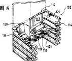
Fig. 5 is the decomposition diagram of the part of annular belt of the present invention, has wherein cut a part of belt;
Fig. 6 is the lateral plan of a preferred embodiment of the present invention;
Fig. 7 is the transparent view that is used for feed hopper of the present invention;
Fig. 8 is the transparent view that is used for drive pulley of the present invention;
Fig. 9 is the front elevation of vertical belt conveyor system of the present invention.
Below will describe the preferred embodiment of vertical belt conveyor system of the present invention in detail, this system is used for the vertical transport loose unpacked material, and embodiment shows in the accompanying drawings.In all case, identical reference symbol will be used in the identical part of expression among all figure.
The embodiment of preferred vertical belt conveyor system of the present invention as shown in Figure 6, and usually by reference symbol 100 expression.Fig. 6 has shown annular belt 102, cylindrical belt pulley 104, turning wheel 106, support unit 138 and feed hopper part 110.
As illustrated in Figures 5 and 6, annular belt 102 comprises a flat reinforcing rubber base band 112, and this base band has an outside face 113 and inside face 115.The side plate 114 that is made of undulatory reinforcing rubber is connected on the base band 112 along the opposed edge of base band 112.Side plate 114 preferably has integral structure, and forms an integral body with base band.Between two side plates 114, cross flight or batten 118 have formed the groove or the bag 120 that hold loose unpacked material clocklike to be connected along the length direction of belt at interval.The height of batten and side plate can decide according to the volume of groove of wanting to obtain or bag.Similarly, the width of base band 112 can be any desirable size.Generally, the width of belt is littler four (4) inches than the width of belt pulley.
As shown in Figure 5, batten 118 is substantially perpendicular to outside face 113 and traverses across the width of base band 112.Batten 118 is fixed in the groove 122 of horizontal expansion, and this groove is formed on the base band 112 by upright short slab 122, and batten is preferably by being bolted in the groove.In addition, batten 118 also can form with base band 112 integral body.The part 121 of the main body 119 of batten 118 is updip a little, overflows so that prevent the material in the groove 120.Except belt of the present invention did not cross out two side plate 114 this point, such belt composition also was well-known in prior art.
As mentioned above, the endless conveyor of prior art needs change of direction to make loose unpacked material leave groove, thus must make base band prolong the position that side plate, as shown in Figure 2.This structure provides a part of P of base band, so that contact with turning to belt pulley or roller.In conveyer system of the present invention, owing to do not need to turn to belt pulley, so side plate 114 can be configured in the edge of base band 112.Therefore, the whole width of base band can be used for cooperating with side plate 114 and batten 118, thereby compares with the rubber tape of the prior art of same width, and groove or bag 120 with bigger volume are provided.As a result, for given baseband width, the band weight of the loose unpacked material of the per unit volume that can carry on base band has reduced.
Shown in Fig. 6 and 4, vertical transport of the present invention system comprises that a discharge belt pulley 124 and one get material belt pulley 126, and annular belt is just dragged between these two belt pulleys.Discharge belt pulley 124 is bearing in the top of vertical conveyor by a support unit 138.Support unit 138 comprises the steel frame 139 of a rigidity, and this steelframe is positioned the top of the vertical stroke of endless belt operation in well-known mode in prior art.Framework 139 should be enough wide, like this,, just can not interfered during around 106 motions of discharge belt pulley 124 and turning wheel at endless belt.Discharge belt pulley 124 preferably is formed from steel, and can be at its outer surface belt one deck overcoat 125, and to increase friction force, to reduce wearing and tearing, this outer putting is preferably with chevron shaped grooved pattern, as shown in Figure 8.Encased on the conveyer belt wheel, are well-known technology friction to be provided and to reduce wearing and tearing.For example, the overcoat on belt pulley can be polysulphide rubbers or stupalith.Also can adopt helping the increase friction and reducing lost material of other.Discharge belt pulley 124 can comprise the annulus 132 of a rise, this annulus is around the line of centers of the cylindrical outer surface of discharge belt pulley 124, so that belt 102 is remained on the belt pulley 124, prevent that belt from carrying out axial motion along the belt pulley outside face.Discharge belt pulley 124 links to each other with a transverse drive shaft 128, and the width of this belt pulley is just over the width of belt.Axle drive shaft 128 is installed in rotation on the pair of bearings 134.Support unit 138 has bearing support 136, and this bearing support is installed in the fixed position with bearing 134.
When annular belt is dragged on discharge belt pulley 124, discharge belt pulley 124 forms on annular belt and has determined a radius of curvature R 1, as shown in Figure 4, this radius is enough little, when annular belt around the discharge pulley movements and when getting the motion of material belt pulley 126, the centnifugal force that is produced can overcome gravity, and that material is discharged groove 120 is outer or force loose unpacked material to be packed in bag or the groove 120.The radius of discharge belt pulley is a parameter of belt running velocity.
The minimum radius of refuse rotor is that the permission minimum bending radius of belt by the band side plate is determined.The radius of discharge belt pulley can determine with following formula: R1<V
2/ g, the wherein radius of R1=discharge belt pulley; The linear velocity of material in the V=bag is a unit with the feet per second; And the G=acceleration due to gravity, unit is feet per second/second.With reference to figure 6, the present invention also adopts one to get material belt pulley 126 again, and this belt pulley is configured in the stroke lowest part of annular belt.Get material belt pulley 126 below the discharge belt pulley.Under many circumstances, the discharge belt pulley is expected that with getting it is favourable that belt pulley places in the same vertical plane surface.If conveyer is to be used for very dark tunnel, belt pulley is in same plane, and needed space is littler.In addition, get material belt pulley 126 and can be configured on discharge belt pulley 124 horizontal positions, to help to form radius of curvature R 1.
Get material belt pulley 126 location and be installed on the lateral shaft 146.This is got the material belt pulley and is also made by steel cylinder, yet, do not need to cover polysulphide rubbers at its outside face.Bearing 148 is installed in the opposite end of axle 146 on the adjustable bearing structure 150.The supporting structure adjusted 150 in the present embodiment of the present invention is independent of the support unit 138 that is used to support discharge belt pulley 124.Getting material belt pulley 126 and generally be not driven, also can be idle pulley or base wheel or belt pulley.
The bearing 148 that is supporting the transverse axis 146 of getting material belt pulley 126 is adjustable in vertical direction.Vertical adjustable supporting structure 150 allows to get material belt pulley 126 and moves about two feet in vertical direction.This can make annular belt 102 be dragged around getting material belt pulley and discharge belt pulley, and when this belt when each belt pulley is dragged, expect belt pulley 126 by moving vertically downward to get, the device of a tensioning around the trailing annular belt of belt pulley is provided.Adjustable bearing structure 150 can be the thread regulator 152 that is connected on each bearing.Bolt passes bearing and supporting 152.The bolt of rotation by bearing can make to be got the material belt pulley and rises in the material scope or descend two feet get.In addition, bearing can be the bearing that is free to slide of a band counterweight, so that keep suitable pulling force on the annular belt.
Getting material belt pulley 126 does not need to have identical diameter with discharge belt pulley 124, but the general range of these two diameter pulleys is between 20 inches to 48 inches.Expect that for getting belt pulley 126 and discharge belt pulley 124, representative type belt pulley end width are that belt is wide and add 4 inches.
The present invention also comprises near the turning wheel 174 of ranking discharge belt pulley 124.The shape of these turning wheels 174 is similar to the shape of discharge belt pulley, but diameter is less.Turning wheel 174 is bearing on the support unit 138 (not demonstration) by each axle and Bearing assembly, and is arranged in a row near the extreme higher position of the upward stroke of annular belt.Turning wheel 174 is positioned at the upstream of discharge belt pulley 124.Turning wheel 174 provides a mild bending spring during near the discharge belt pulley for annular belt 102.The effect of turning wheel is that the motion for belt brings mild direction to change, and this point is known altogether in prior art.The radius of curvature R as shown in Figure 62 that is produced by turning wheel 174 is enough big, is contained in the loose unpacked material in the groove 120 like this, can not leave groove because of the centnifugal force that was produced when annular belt moved turning wheel 174.Expect that with getting belt pulley 126 is the same with discharge belt pulley 124, turning wheel 174 contacts with the whole width of the inside face 115 of annular belt 102.
With reference to figure 6 and 7, the present invention also comprises feed hopper parts 110, and wherein material is sent in regional A on the endless belt of getting in the upward stroke of expecting between belt pulley and the discharge belt pulley.Near the upward stroke 156 of these hopper 154 close annular belts 102.Hopper 154 comprises a base plate 158 that angle is downward, and the width of this base plate is identical with the width of annular belt usually, near the termination belt 102 that moves up of this base plate.Pair of side plates 160 is configured in the both sides of this base plate 158, and near the same termination belt 102 that moves up.The limit cover 162 of a suspention downwards is connected on the dwell section of hopper hang plate 158, and extends downward vertically, near the belt of upward movement.This limit cover part 162 of feed hopper will be below feed hopper the termination of swash plate 158 stretch out, reach at least between the batten 118 of belt 102, with prevent when loose unpacked material when the inclined-plane moves downward the groove 120 that enters on the belt, loose unpacked material overflows.
Loose unpacked material can be transported to the hopper 154 by the another part or the position, underground hole of a horizontal conveyer 166 from the ore deposit by truck or the more generally situation shown in Fig. 6 and 7.
The present invention also provides a kind of discharge chute 167, and this skewed slot comprises near a discharge shell 168 that is configured in the discharge belt pulley 124.This discharge shell separates with annular belt 102 and is covered with annular belt 102 along discharge belt pulley 124 trailing those parts.This discharge shell 168 preferably is formed from steel, and is supported by any suitable support unit (not showing).For example, shell 168 can be connected the vicinity near the discharge belt pulley, receives the loose unpacked material of discharging from vertical conveyor.This discharge shell comprises a dash plate 170, this dash plate separates with annular belt, and, tangent with annular belt little by little around discharge belt pulley 124 trailing those parts, so that with material from the belt proper container that leads, as horizontal conveyer 172 or truck or other material handling apparatus.
As shown in Figure 6, at discharge belt pulley 124 with get material and do not have also can use the present invention under the condition of intermediate support structure between the belt pulley 126.For material handling on very long distance, comprise under the condition of 600 feet or bigger vertical transport height, adopt the present invention just convenient especially.With the structure that need in the whole vertical stroke of annular belt, all need to support, can set up device as shown in Figure 6 quickly and effectively with expense seldom.
In another embodiment as shown in Figure 3, this vertical conveyor system has adopted an intermediate support structure.This supporting structure comprises the right cylinder 178 of four band footing 176, these four rectangular or square configuration of right cylinder.Each right cylinder is by linking to each other with adjacent two right cylinders with the horizontal reinforcement 180 of various arranged spaced and cross bar 182.The structure of support unit can be the variety of way known to the prior art.The basic characteristic of support unit is that it can back(-)up belt wheel, belt and be carried at the weight of the material in the vertical belt conveyor.Yet, it should be noted that design of the present invention comprises less belt pulley and lighter belt, has so just reduced the weight of the required supporting of support unit.
In practical operation, the present invention shown in Figure 6 resembles configuration as described above, and driving motor 142 meshes with the axle drive shaft of discharge belt pulley, and discharge belt pulley drive shaft annular belt 102.Annular belt is expected that with getting belt pulley 126 drags by discharge belt pulley 124.The inside face of belt at first is placed on the discharge belt pulley 124, and remaining belt puts down tunnel or lifting region, arrive and get material belt pulley 126.This annular belt can be got material belt pulley 126 then and be dragged, and this belt pulley is being equipped adjustable bearing parts, allows belt to be fixed on the belt pulley, and then with adjustable bolt 152 tightening belts.Feed hopper 154 is delivered to and entered to loose unpacked material preferably by horizontal conveyer 166, then along hopper inclined bottom plate 158 to lower slider, enter the mobile bag or the groove 120 that are formed on the annular belt, at this moment groove 120 moves in vertical direction, passes through feed hopper.When annular belt 102 moved to turning wheel 174 places of the vertex that is in the belt stroke in its vertical stroke, loose unpacked material was stayed in the groove 120.Along with loose unpacked material moved turning wheel, will tilt towards discharge shell and discharge belt pulley gradually.When generally bigger bending spring by being formed by turning wheel of belt 102, the material in material bag and the groove is still stayed in the groove 120.Yet along with the bag 120 that is full of material during near the discharge belt pulley, the bending spring of annular belt 102 diminishes rapidly, the centnifugal force that acts on the material in the bag makes material leave bag, enter the discharge shell, the damping of shocks plate, and finally on horizontal conveyer, stop.
From the above mentioned, it is apparent that the vertical belt conveyor that the invention provides a kind of new uniqueness, be used for the delivery of bulk material.Though adopted specification sheets that application of the present invention is illustrated, for a person skilled in the art, when design and structure vertical belt conveyor system, can carry out various modifications and variations, and not depart from the scope of the present invention and spirit.
For those skilled in the art, from specification sheets of the present invention and practical application, other embodiments of the invention are tangible.And this specification sheets and embodiment are considered to only be example, and real scope and spirit essence of the present invention is indicated by following claim.
Claims (23)
1. the gig of a loose unpacked material comprises:
One first back(-)up belt wheel and second back(-)up belt with said first back(-)up belt wheel arranged perpendicular are taken turns;
Near the turning wheel of one row arrangement side said first back(-)up belt wheel;
Be used for making the actuating device of said first back(-)up belt wheel rotation;
An annular belt, side at said belt has a back(-)up belt wheel mating surfaces, there is one group of loose unpacked material to carry part on its opposed surface, said annular belt is dragged around said first and second back(-)up belts wheel, when by said turning wheel, said annular belt has the bending spring of a pre-sizing, preventing to act on the centnifugal force that said loose unpacked material carries the loose unpacked material in the part is discharged from it, when taking turns by said first back(-)up belt, said annular belt has the bending spring of a pre-sizing, makes that act on the centnifugal force that said loose unpacked material carries the loose unpacked material in the part discharges loose unpacked material;
First support unit of said first back(-)up belt wheel of supporting; With
The second separate support parts of said second back(-)up belt wheel of supporting.
2. according to the gig of claim 1, it is characterized in that: said annular belt comprises a base band of strengthening rubber, be connected the corrugated side plate of transverse edge of said base band and the batten of one group of longitudinal interval, these battens are vertical with said base band basically, and between said side plate, crossed said base band, and formed said loose unpacked material and carry part.
3. according to the gig of claim 2, it is characterized in that: said side plate and said base band are whole to be formed.
4. according to the gig of claim 1, it is characterized in that: said first back(-)up belt wheel comprises a cylindrical steel cylinder, and this steel cylinder has layer of material at its cylindrical surface, has the friction force of driving and abrasion resistant surface to provide.
5. according to the gig of claim 4, it is characterized in that: said first back(-)up belt wheel comprises that a ring-type on the cylindrical outer surface that is configured in said belt pulley rises part.
6. according to the gig of claim 1, it is characterized in that: said second back(-)up belt wheel comprise one to the similar cylindrical steel cylinder of the said first back(-)up belt size of wheel.
7. according to the gig of claim 1, it is characterized in that: said second support unit comprises and is installed in a bearing on the support accessory, so that support said second back(-)up belt wheel, and comprise a rotating bolt, this bolt is vertically by said bearing and support accessory configuration, so as with respect to said supports vertical move said bearing.
8. according to the gig of claim 1, it is characterized in that: said first back(-)up belt wheel is configured in the top of said second back(-)up belt wheel.
9. the gig according to claim 1 also comprises a discharge shell, this discharge shell is configured near the said discharge belt pulley, has a hopper, this hopper partly separates around trailing that of first back(-)up belt wheel with annular belt, also comprise at least one deflecting plate, this deflecting plate is downward-sloping from said base band, and there is one at the side plate of said base band and near the front edge the batten, also has substantially parallel with said hopper and separate a with it base plate, the front edge of this base plate is positioned near the side plate and batten of said base band, so that the loose unpacked material that carries in the part from said loose unpacked material is led.
10. a gig comprises:
One first back(-)up belt wheel is taken turns with vertical and horizontal arrangement second back(-)up belt with said first back(-)up belt wheel;
Near the turning wheel of one row arrangement side said first back(-)up belt wheel;
Be used for making the actuating device of said first back(-)up belt wheel rotation;
An annular belt, side at said belt has a back(-)up belt wheel mating surfaces, there is one group of loose unpacked material to carry part on its opposed surface, said annular belt is dragged around said first and second back(-)up belts wheel, when by said turning wheel, said annular belt has the bending spring of a pre-sizing, preventing to act on the centnifugal force that said loose unpacked material carries the loose unpacked material in the part is discharged from it, when taking turns by said first back(-)up belt, said annular belt has the bending spring of a pre-sizing, makes that act on the centnifugal force that said loose unpacked material carries the loose unpacked material in the part discharges loose unpacked material;
First support unit of said first back(-)up belt wheel of supporting;
The second separate support parts of said second back(-)up belt wheel of supporting;
A feed hopper, this feed hopper has a bevelled base plate and adjacent side plate, base plate and side plate all end at said endless belt to ending near the movement travel, said hopper comprises a limit cover part, this limit cover part is suspended in midair downwards from the end margin of said inclined floor, and extend a distance downwards, this distance equals said loose unpacked material at least and carries distance between the part; With
A near discharge shell that is configured in the said discharge belt pulley and has a hopper, this discharge shell separates around trailing that some of first back(-)up belt wheel with annular belt, has one at least from the downward-sloping deflecting plate of said base band, this deflecting plate has one to be positioned at the side plate of said base band and near the front edge the batten, and base plate substantially parallel with said hopper and that separate with this hopper, this base plate has one to be positioned at the side plate of said base band and near the front edge the batten, so that the loose unpacked material that carries in the part from loose unpacked material is led.
11. gig according to claim 10, it is characterized in that: said annular belt comprises a base band of strengthening rubber, be connected the corrugated side plate of transverse edge of said base band and the batten of one group of longitudinal interval, these battens are vertical with said base band basically, and between said side plate, crossed said base band, and formed said loose unpacked material and carry part.
12. the gig according to claim 11 is characterized in that: said side plate and said base band are whole to be formed.
13. the gig according to claim 10 is characterized in that: said first back(-)up belt wheel comprises a cylindrical steel cylinder, and this steel cylinder has layer of material at its cylindrical surface, has the friction force of driving and abrasion resistant surface to provide.
14. the gig according to claim 13 is characterized in that: said first back(-)up belt wheel comprises that a ring-type that is configured in the cylindrical outer surface of said belt pulley rises part.
15. the gig according to claim 10 is characterized in that: said second back(-)up belt wheel comprise one to the similar cylindrical steel cylinder of the said first back(-)up belt size of wheel.
16. gig according to claim 10, it is characterized in that: said second support unit comprises and is installed in a bearing on the support accessory, so that support said second back(-)up belt wheel, and comprise a rotating bolt, this bolt is by said bearing and support accessory arranged perpendicular, so as with respect to said supports vertical move said bearing.
17. the gig according to claim 10 is characterized in that: said first back(-)up belt wheel is configured in the top of said second back(-)up belt wheel.
18. a gig comprises:
One first back(-)up belt wheel and second back(-)up belt with said first back(-)up belt wheel arranged perpendicular are taken turns, and said first back(-)up belt wheel comprises a cylindrical steel cylinder, and said second back(-)up belt wheel comprises a cylindrical steel cylinder;
Near the turning wheel of one row arrangement side said first back(-)up belt wheel, said turning wheel comprises cylindrical steel cylinder, the diameter that the diameter of this steel cylinder is taken turns less than said first back(-)up belt basically;
An annular belt, this belt has a predetermined width, this width is slightly less than the width of said first back(-)up belt wheel, side at said belt has a back(-)up belt wheel mating surfaces, there is one group of loose unpacked material to carry part on its opposed surface, said annular belt is dragged around said first and second back(-)up belts wheel, and upward stroke and descending stroke are arranged, when by said turning wheel, said annular belt has the bending spring of a pre-sizing, preventing to act on the centnifugal force that said loose unpacked material carries the loose unpacked material in the part is discharged from it, when taking turns by said first back(-)up belt, said annular belt has the bending spring of a pre-sizing, makes that act on the centnifugal force that said loose unpacked material carries the loose unpacked material in the part discharges loose unpacked material;
Upward stroke that is positioned at said annular belt and near the highest part, so as to support first back(-)up belt wheel first supporting part;
Vertical second adjustable separate support parts, so that support said second back(-)up belt wheel, the said second separate support parts comprise the bearing that is used to support said second back(-)up belt wheel, this bearing installation is on a support accessory, and comprise rotating bolt, this bolt is by said bearing and said support accessory, so that with respect to the said bearing of said support accessory vertical shifting;
Link to each other with said first back(-)up belt wheel, so that rotate the actuating device of said first back(-)up belt wheel;
A feed hopper, this feed hopper has a bevelled base plate and adjacent side plate, base plate and side plate all end at said endless belt to ending near the movement travel, said hopper comprises a limit cover part, this limit cover part is suspended in midair downwards from the end margin of said inclined floor, and extend a distance downwards, this distance equals said loose unpacked material at least and carries distance between the part; With
Discharge shell with refraction bucket, this refraction bucket is taken turns trailing part with annular belt around first back(-)up belt and is separated, also has row's deflecting plate, these deflecting plates are downward-sloping from said base band, its front edge is positioned near the side plate and batten of said base band, also have basic parallel with a said hopper and base plate that separate with this hopper, its front edge is positioned near the side plate and batten of said base band, so that the loose unpacked material that carries part from said loose unpacked material is led.
19. gig according to claim 18, it is characterized in that: said annular belt comprises a base band of strengthening rubber, be connected the corrugated side plate of transverse edge of said base band and the batten of one group of longitudinal interval, these battens are vertical with said base band basically, and between said side plate, crossed said base band, and formed said loose unpacked material and carry part.
20. the gig according to claim 19 is characterized in that: said side plate and said base band are whole to be formed.
21. the gig according to claim 18 is characterized in that: the ring-type that said first back(-)up belt wheel is included on the said belt pulley cylindrical outer surface rises part.
22. the gig according to claim 18 is characterized in that: said second back(-)up belt wheel comprise one to the similar cylindrical steel cylinder of the said first back(-)up belt size of wheel.
23. the gig according to claim 18 is characterized in that: said first back(-)up belt wheel is configured on said second belt pulley.
Applications Claiming Priority (2)
| Application Number | Priority Date | Filing Date | Title |
|---|---|---|---|
| US08/642,136 US5975283A (en) | 1996-05-02 | 1996-05-02 | Vertical belt conveyor system |
| US08/642,136 | 1996-05-02 |
Publications (1)
| Publication Number | Publication Date |
|---|---|
| CN1246833A true CN1246833A (en) | 2000-03-08 |
Family
ID=24575353
Family Applications (1)
| Application Number | Title | Priority Date | Filing Date |
|---|---|---|---|
| CN97195731A Pending CN1246833A (en) | 1996-05-02 | 1997-05-01 | Vertical belt conveyor system |
Country Status (5)
| Country | Link |
|---|---|
| US (1) | US5975283A (en) |
| JP (1) | JP2000509356A (en) |
| CN (1) | CN1246833A (en) |
| WO (1) | WO1997041052A1 (en) |
| ZA (1) | ZA973798B (en) |
Cited By (3)
| Publication number | Priority date | Publication date | Assignee | Title |
|---|---|---|---|---|
| CN111271116A (en) * | 2020-04-03 | 2020-06-12 | 荆门怡盛源环保科技有限公司 | Belt conveyor of coal mining roadway and installation method |
| CN113086511A (en) * | 2021-03-23 | 2021-07-09 | 武汉理工大学 | Novel high-speed belt bucket elevator |
| WO2022089251A1 (en) * | 2020-10-27 | 2022-05-05 | 中冶南方工程技术有限公司 | Rectangular material warehouse having multi-channel material-feeding and foldable material-scraping |
Families Citing this family (17)
| Publication number | Priority date | Publication date | Assignee | Title |
|---|---|---|---|---|
| US6571935B1 (en) * | 2000-06-22 | 2003-06-03 | Cambelt International Corporation | Monolithic belt with reinforced sidewall |
| US6382404B1 (en) | 2000-12-21 | 2002-05-07 | Habasit Ag | Corrugated flight module |
| DE10320963A1 (en) * | 2003-05-09 | 2004-12-16 | Siemens Ag | Conveyor system, in particular an airport baggage conveyor system, and an unloading device of a conveyor system for containers for transporting goods, in particular luggage |
| AT502181B1 (en) * | 2005-09-07 | 2007-02-15 | Haselboeck Dieter | LUBRICATION FOR A CONVEYOR BELT |
| US8671856B2 (en) | 2009-02-02 | 2014-03-18 | Deere & Company | Planting unit for a seeding machine having blocking member to control hand-off of seed from a seed meter to a seed delivery system |
| US8850995B2 (en) | 2009-02-02 | 2014-10-07 | Deere & Company | Seeding machine with seed delivery system |
| JP2011032071A (en) * | 2009-08-05 | 2011-02-17 | Tiger Kawashima Co Ltd | Granular material carrying device |
| DE102012103963A1 (en) * | 2012-05-07 | 2013-11-07 | Contitech Transportbandsysteme Gmbh | Conveyor with improved energy requirements |
| TWI555579B (en) * | 2012-11-01 | 2016-11-01 | Taiwan Keyarrow Ind Co Ltd | Conveying crushing device |
| ES2824173T3 (en) * | 2015-10-08 | 2021-05-11 | Laitram Llc | End Roller Assembly for a Conveyor Belt |
| JP6859082B2 (en) * | 2016-11-22 | 2021-04-14 | 株式会社大林組 | Belt conveyor device |
| US10743460B2 (en) | 2017-10-03 | 2020-08-18 | Ag Leader Technology | Controlled air pulse metering apparatus for an agricultural planter and related systems and methods |
| AT520651B1 (en) * | 2018-04-04 | 2019-06-15 | Innova Patent Gmbh | vertical conveyor |
| US10806084B2 (en) | 2018-05-07 | 2020-10-20 | Cnh Industrial America Llc | System for unloading harvested crop from an agricultural harvester |
| US11877530B2 (en) | 2019-10-01 | 2024-01-23 | Ag Leader Technology | Agricultural vacuum and electrical generator devices, systems, and methods |
| KR102278780B1 (en) * | 2020-12-08 | 2021-07-20 | 주식회사 엔시스 | Thickness measuring equipment for polar plate |
| CN117022995B (en) * | 2023-09-28 | 2023-12-22 | 杭州奥拓机电股份有限公司 | L-shaped conveying belt machine |
Family Cites Families (33)
| Publication number | Priority date | Publication date | Assignee | Title |
|---|---|---|---|---|
| US998763A (en) * | 1911-07-25 | Clayton M Passett | Conveyer for concrete-mixing machines. | |
| US299656A (en) * | 1884-06-03 | leso urd | ||
| US253896A (en) * | 1882-02-21 | Said fred | ||
| US587049A (en) * | 1897-07-27 | Elevator | ||
| US2685957A (en) * | 1954-08-10 | Conveyer | ||
| US744288A (en) * | 1902-05-13 | 1903-11-17 | John George Young | Water-elevator. |
| US1012133A (en) * | 1911-11-11 | 1911-12-19 | Patrick John Higgins | Loading apparatus. |
| US1133008A (en) * | 1914-08-10 | 1915-03-23 | Frederic S Converse | Coal-loading machine. |
| US1242249A (en) * | 1917-05-12 | 1917-10-09 | James B Seaverns | Unloading apparatus. |
| US1391703A (en) * | 1918-02-23 | 1921-09-27 | Sturtevant Mill Co | Elevator |
| US1830603A (en) * | 1927-08-08 | 1931-11-03 | Miles Mfg Company | Bucket conveyer |
| US1892881A (en) * | 1930-12-23 | 1933-01-03 | Chas M Fuller Corp Ltd | Elevating power shovel |
| US1944932A (en) * | 1932-07-22 | 1934-01-30 | Blaine B Gemeny | Elevator bucket |
| US2084920A (en) * | 1936-04-16 | 1937-06-22 | Peter J P Schrag | Elevator structure |
| US2122036A (en) * | 1937-05-13 | 1938-06-28 | K I Willis Corp | Elevator cup |
| US2347437A (en) * | 1941-06-02 | 1944-04-25 | Conveyor Company | Storage device |
| US2711816A (en) * | 1952-07-08 | 1955-06-28 | F B Wright Company | Troughed conveyer belt |
| FR1081588A (en) * | 1953-07-24 | 1954-12-21 | Rubber conveyor belt, compartmentalized or not, with side edges | |
| US2852126A (en) * | 1957-02-28 | 1958-09-16 | Ohlberg Karl-Heinz | Centrifugal belt conveyer |
| US2973854A (en) * | 1958-01-13 | 1961-03-07 | Jeffrey Mfg Co | Bucket elevator |
| US3147851A (en) * | 1961-12-15 | 1964-09-08 | Dietrich Werner | Conveyor |
| FR1324286A (en) * | 1962-03-02 | 1963-04-19 | Belt conveyor, sheathed | |
| US3236365A (en) * | 1962-10-31 | 1966-02-22 | Link Belt Co | Self-cleaning elevator boot device |
| GB1104437A (en) * | 1964-10-29 | 1968-02-28 | Georg Schardt | Improvements in or relating to conveyor belts |
| DE2100364B1 (en) * | 1971-01-07 | 1972-06-29 | Conrad Scholtz Ag, 2000 Hamburg | Conveyor belt with corrugated side walls |
| US4333561A (en) * | 1978-07-10 | 1982-06-08 | Schlegel Hans J | Elevator head material guide means |
| CA1225057A (en) * | 1984-05-29 | 1987-08-04 | George T. Gough | Elevating conveyor |
| FR2567494B1 (en) * | 1984-07-12 | 1986-07-18 | Tech Manutention Et | BUCKET LIFT COMPRISING MEANS FOR SLOWING DOWN THE BUCKET IN THE LOADING AREA |
| FR2588250B1 (en) * | 1985-10-07 | 1994-07-08 | Tricot Robert | CONVEYOR BELT WITH CONTAINER EDGES |
| JPS6450611A (en) * | 1987-08-21 | 1989-02-27 | Nec Corp | Phase shifter |
| US5143203A (en) * | 1991-05-14 | 1992-09-01 | Merrill Iron & Steel, Inc. | Granular material transfer apparatus |
| JPH06135524A (en) * | 1992-10-27 | 1994-05-17 | Iseki Tory Tech Inc | Conveyer device |
| US5564878A (en) * | 1994-11-04 | 1996-10-15 | Texmarc Conveyor Company | Apparatus and method for continuous handling of bulk materials |
-
1996
- 1996-05-02 US US08/642,136 patent/US5975283A/en not_active Expired - Fee Related
-
1997
- 1997-05-01 CN CN97195731A patent/CN1246833A/en active Pending
- 1997-05-01 JP JP9539184A patent/JP2000509356A/en active Pending
- 1997-05-01 WO PCT/US1997/007236 patent/WO1997041052A1/en active Search and Examination
- 1997-05-02 ZA ZA9703798A patent/ZA973798B/en unknown
Cited By (3)
| Publication number | Priority date | Publication date | Assignee | Title |
|---|---|---|---|---|
| CN111271116A (en) * | 2020-04-03 | 2020-06-12 | 荆门怡盛源环保科技有限公司 | Belt conveyor of coal mining roadway and installation method |
| WO2022089251A1 (en) * | 2020-10-27 | 2022-05-05 | 中冶南方工程技术有限公司 | Rectangular material warehouse having multi-channel material-feeding and foldable material-scraping |
| CN113086511A (en) * | 2021-03-23 | 2021-07-09 | 武汉理工大学 | Novel high-speed belt bucket elevator |
Also Published As
| Publication number | Publication date |
|---|---|
| AU714470B2 (en) | 2000-01-06 |
| US5975283A (en) | 1999-11-02 |
| WO1997041052A1 (en) | 1997-11-06 |
| ZA973798B (en) | 1997-12-01 |
| AU2819297A (en) | 1997-11-19 |
| JP2000509356A (en) | 2000-07-25 |
Similar Documents
| Publication | Publication Date | Title |
|---|---|---|
| CN1246833A (en) | Vertical belt conveyor system | |
| CN104973412B (en) | Belt type conveying and transferring device | |
| CN1262824C (en) | Chain converyor in form of scales | |
| CN1010224B (en) | Bulk cargo load and unload device | |
| CN1036374A (en) | A kind of stacking machine that aligns container | |
| CN1817759A (en) | Semicircular belt conveyor with deep groove and big dig | |
| CN109312572B (en) | Lifting device | |
| CN1213636A (en) | Side-by-side belt conveyer system and method of use | |
| CN1088534A (en) | Belting | |
| CN1056584C (en) | Vertically lifting method and lifter thereof | |
| CN2675629Y (en) | Vertical elevator | |
| CN1143597A (en) | Device for continuously unloading bulk goods from ship or other bin | |
| CN1074741C (en) | Apparatus and method for unloading | |
| CN1120510A (en) | Conveyor for continuous haulage system | |
| CN1045572C (en) | Belt cableway conveyer | |
| CN210914014U (en) | Hanging rope type conveyor | |
| GB2189765A (en) | Cargo ship with unloading apparatus | |
| CN114633988A (en) | Bucket elevator for calcium oxide production | |
| CN207121141U (en) | A kind of band continuous vertical conveyor of bucket type | |
| AU714470C (en) | Vertical belt conveyor system | |
| KR20050034152A (en) | Apparatus for preventing carried objects from dropping out of belts conveyor | |
| CN1045076A (en) | Crawler-type rubber belt conveyer | |
| CN1152812C (en) | Unloader | |
| RU2235051C2 (en) | Method of and device for treatment of loose loads | |
| CN2491419Y (en) | Extensible stacking loading pipe for storagehouse |
Legal Events
| Date | Code | Title | Description |
|---|---|---|---|
| C06 | Publication | ||
| PB01 | Publication | ||
| C10 | Entry into substantive examination | ||
| SE01 | Entry into force of request for substantive examination | ||
| AD01 | Patent right deemed abandoned | ||
| C20 | Patent right or utility model deemed to be abandoned or is abandoned |