CN1227547C - 单模光纤及制造单模光纤的方法 - Google Patents
单模光纤及制造单模光纤的方法 Download PDFInfo
- Publication number
- CN1227547C CN1227547C CNB018109144A CN01810914A CN1227547C CN 1227547 C CN1227547 C CN 1227547C CN B018109144 A CNB018109144 A CN B018109144A CN 01810914 A CN01810914 A CN 01810914A CN 1227547 C CN1227547 C CN 1227547C
- Authority
- CN
- China
- Prior art keywords
- refractive index
- coated layer
- core
- internal coated
- layer part
- Prior art date
- Legal status (The legal status is an assumption and is not a legal conclusion. Google has not performed a legal analysis and makes no representation as to the accuracy of the status listed.)
- Expired - Lifetime
Links
Images


Classifications
-
- G—PHYSICS
- G02—OPTICS
- G02B—OPTICAL ELEMENTS, SYSTEMS OR APPARATUS
- G02B6/00—Light guides; Structural details of arrangements comprising light guides and other optical elements, e.g. couplings
- G02B6/02—Optical fibres with cladding with or without a coating
- G02B6/036—Optical fibres with cladding with or without a coating core or cladding comprising multiple layers
- G02B6/03694—Multiple layers differing in properties other than the refractive index, e.g. attenuation, diffusion, stress properties
-
- G—PHYSICS
- G02—OPTICS
- G02B—OPTICAL ELEMENTS, SYSTEMS OR APPARATUS
- G02B6/00—Light guides; Structural details of arrangements comprising light guides and other optical elements, e.g. couplings
- G02B6/02—Optical fibres with cladding with or without a coating
-
- C—CHEMISTRY; METALLURGY
- C03—GLASS; MINERAL OR SLAG WOOL
- C03B—MANUFACTURE, SHAPING, OR SUPPLEMENTARY PROCESSES
- C03B37/00—Manufacture or treatment of flakes, fibres, or filaments from softened glass, minerals, or slags
- C03B37/01—Manufacture of glass fibres or filaments
- C03B37/012—Manufacture of preforms for drawing fibres or filaments
- C03B37/014—Manufacture of preforms for drawing fibres or filaments made entirely or partially by chemical means, e.g. vapour phase deposition of bulk porous glass either by outside vapour deposition [OVD], or by outside vapour phase oxidation [OVPO] or by vapour axial deposition [VAD]
- C03B37/018—Manufacture of preforms for drawing fibres or filaments made entirely or partially by chemical means, e.g. vapour phase deposition of bulk porous glass either by outside vapour deposition [OVD], or by outside vapour phase oxidation [OVPO] or by vapour axial deposition [VAD] by glass deposition on a glass substrate, e.g. by inside-, modified-, plasma-, or plasma modified- chemical vapour deposition [ICVD, MCVD, PCVD, PMCVD], i.e. by thin layer coating on the inside or outside of a glass tube or on a glass rod
- C03B37/01807—Reactant delivery systems, e.g. reactant deposition burners
- C03B37/01815—Reactant deposition burners or deposition heating means
- C03B37/01823—Plasma deposition burners or heating means
- C03B37/0183—Plasma deposition burners or heating means for plasma within a tube substrate
-
- C—CHEMISTRY; METALLURGY
- C03—GLASS; MINERAL OR SLAG WOOL
- C03C—CHEMICAL COMPOSITION OF GLASSES, GLAZES OR VITREOUS ENAMELS; SURFACE TREATMENT OF GLASS; SURFACE TREATMENT OF FIBRES OR FILAMENTS MADE FROM GLASS, MINERALS OR SLAGS; JOINING GLASS TO GLASS OR OTHER MATERIALS
- C03C13/00—Fibre or filament compositions
- C03C13/04—Fibre optics, e.g. core and clad fibre compositions
-
- G—PHYSICS
- G02—OPTICS
- G02B—OPTICAL ELEMENTS, SYSTEMS OR APPARATUS
- G02B6/00—Light guides; Structural details of arrangements comprising light guides and other optical elements, e.g. couplings
- G02B6/02—Optical fibres with cladding with or without a coating
- G02B6/02395—Glass optical fibre with a protective coating, e.g. two layer polymer coating deposited directly on a silica cladding surface during fibre manufacture
-
- G—PHYSICS
- G02—OPTICS
- G02B—OPTICAL ELEMENTS, SYSTEMS OR APPARATUS
- G02B6/00—Light guides; Structural details of arrangements comprising light guides and other optical elements, e.g. couplings
- G02B6/02—Optical fibres with cladding with or without a coating
- G02B6/036—Optical fibres with cladding with or without a coating core or cladding comprising multiple layers
- G02B6/03616—Optical fibres characterised both by the number of different refractive index layers around the central core segment, i.e. around the innermost high index core layer, and their relative refractive index difference
- G02B6/03622—Optical fibres characterised both by the number of different refractive index layers around the central core segment, i.e. around the innermost high index core layer, and their relative refractive index difference having 2 layers only
-
- G—PHYSICS
- G02—OPTICS
- G02B—OPTICAL ELEMENTS, SYSTEMS OR APPARATUS
- G02B6/00—Light guides; Structural details of arrangements comprising light guides and other optical elements, e.g. couplings
- G02B6/02—Optical fibres with cladding with or without a coating
- G02B6/036—Optical fibres with cladding with or without a coating core or cladding comprising multiple layers
- G02B6/03616—Optical fibres characterised both by the number of different refractive index layers around the central core segment, i.e. around the innermost high index core layer, and their relative refractive index difference
- G02B6/03638—Optical fibres characterised both by the number of different refractive index layers around the central core segment, i.e. around the innermost high index core layer, and their relative refractive index difference having 3 layers only
-
- G—PHYSICS
- G02—OPTICS
- G02B—OPTICAL ELEMENTS, SYSTEMS OR APPARATUS
- G02B6/00—Light guides; Structural details of arrangements comprising light guides and other optical elements, e.g. couplings
- G02B6/02—Optical fibres with cladding with or without a coating
- G02B6/036—Optical fibres with cladding with or without a coating core or cladding comprising multiple layers
- G02B6/03616—Optical fibres characterised both by the number of different refractive index layers around the central core segment, i.e. around the innermost high index core layer, and their relative refractive index difference
- G02B6/03661—Optical fibres characterised both by the number of different refractive index layers around the central core segment, i.e. around the innermost high index core layer, and their relative refractive index difference having 4 layers only
-
- G—PHYSICS
- G02—OPTICS
- G02B—OPTICAL ELEMENTS, SYSTEMS OR APPARATUS
- G02B6/00—Light guides; Structural details of arrangements comprising light guides and other optical elements, e.g. couplings
- G02B6/02—Optical fibres with cladding with or without a coating
- G02B6/036—Optical fibres with cladding with or without a coating core or cladding comprising multiple layers
- G02B6/03616—Optical fibres characterised both by the number of different refractive index layers around the central core segment, i.e. around the innermost high index core layer, and their relative refractive index difference
- G02B6/03688—Optical fibres characterised both by the number of different refractive index layers around the central core segment, i.e. around the innermost high index core layer, and their relative refractive index difference having 5 or more layers
-
- C—CHEMISTRY; METALLURGY
- C03—GLASS; MINERAL OR SLAG WOOL
- C03B—MANUFACTURE, SHAPING, OR SUPPLEMENTARY PROCESSES
- C03B2201/00—Type of glass produced
- C03B2201/06—Doped silica-based glasses
- C03B2201/08—Doped silica-based glasses doped with boron or fluorine or other refractive index decreasing dopant
- C03B2201/12—Doped silica-based glasses doped with boron or fluorine or other refractive index decreasing dopant doped with fluorine
-
- C—CHEMISTRY; METALLURGY
- C03—GLASS; MINERAL OR SLAG WOOL
- C03B—MANUFACTURE, SHAPING, OR SUPPLEMENTARY PROCESSES
- C03B2203/00—Fibre product details, e.g. structure, shape
- C03B2203/10—Internal structure or shape details
- C03B2203/22—Radial profile of refractive index, composition or softening point
- C03B2203/24—Single mode [SM or monomode]
Landscapes
- Physics & Mathematics (AREA)
- Chemical & Material Sciences (AREA)
- Optics & Photonics (AREA)
- General Physics & Mathematics (AREA)
- Engineering & Computer Science (AREA)
- Materials Engineering (AREA)
- Organic Chemistry (AREA)
- General Chemical & Material Sciences (AREA)
- Life Sciences & Earth Sciences (AREA)
- Geochemistry & Mineralogy (AREA)
- Chemical Kinetics & Catalysis (AREA)
- General Life Sciences & Earth Sciences (AREA)
- Manufacturing & Machinery (AREA)
- Plasma & Fusion (AREA)
- Manufacture, Treatment Of Glass Fibers (AREA)
- Glass Compositions (AREA)
- Optical Fibers, Optical Fiber Cores, And Optical Fiber Bundles (AREA)
- Optical Integrated Circuits (AREA)
- Surface Treatment Of Glass Fibres Or Filaments (AREA)
Abstract
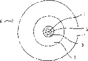
本发明涉及到一种单模光纤的制造方法,它包括一个光传导芯部(4),围绕上述芯部的内覆层部分(3)以及围绕上述内覆层部分的外套部分(1),这其中芯部的折射率比覆层和外套部分区域要大,而且覆层和外套部分区域的折射率实际上相等。
Description
技术领域
本发明涉及到一种单模光纤的制造方法,该光纤包括一个光传导芯部,围绕上述芯部的内覆层部分,以及围绕上述内覆层部分的外套部分,其中芯部的折射率比覆层和外套部分区域的折射率要大,而且覆层和外套部分区域的折射率实际上相等,通过这种方法,可以在内部用一种或多种反应气体充满用作外套部分的石英衬管,以便分别形成内覆层部分和芯部,然后收缩这种设置有层的衬管并且拉制成单模光纤。另外,本发明还涉及到一种单模光纤,它包括一个光传导芯部,围绕上述芯部的一个覆层部分,以及围绕上述内覆层部分的外套部分。
背景技术
这种类型的光纤是公知的并且主要应用于电信技术领域。例如可以参见欧洲专利申请0127227和美国专利5,242,476号及5,838,866号。本文中使用的术语“单模”是本领域技术人员所公知的,无需进一步解释。由于其低衰减和散射的特性,这种光纤特别适合用来构筑往往要跨越数千公里的远距离数据链路,在这样远的距离上,如果光信号的传输是用数量很少的中间放大站完成的,将光纤中的累积信号损失控制在最小是至关重要的。在电信业常用的1550nm传输波长上,通常要求这种光纤中的总衰减不能超过0.25dB/km,最好是不超过0.2dB/km。
尽管目前制造的光纤能够满足有关可允许衰减的所有这些要求,但是往往经过一段时间就会发现有些光纤呈现出明显的衰减增大。深入研究发现这种现象可以归因于氢气从光纤周围逐渐渗出进入光纤,随后会在光纤内形成SiH和SiOH等聚集。这些化合物呈现很强的红外线吸收性,衰减峰值是在约1530和1385nm的波长上。
欧洲专利申请0477435公开了一种解决这一氢气所致衰减问题的方法。根据这种方法,在制造过程中将熔化的光纤完全暴露于含氢的气体,在实际制成光纤之前就保证光纤中所有的结构缺陷点都已被氢原子占据。然而,这种公知方法的缺点在于它对氢气所致的衰减治标不治本。另外,这种公知方法会使制造工艺复杂化,并且因采用了含氢气体会给成品光纤带来额外的污染风险。
美国专利5,090,979公开了一种制造光纤的方法,它依次包括一纯二氧化硅芯部,一个掺杂氟的二氧化硅外层,掺杂氟的二氧化硅衬底层,以及纯二氧化硅的一个载体层,而芯部的折射率和载体层的折射率实际上相等。
美国专利5,033,815公开了一种多模光纤,这种光纤与本发明的单模光纤有明显不同。另外,该文献公开的这种多模光纤依次包含一个GeO2-或Sb2O3-掺杂的芯部,一个F-掺杂的覆层部,最后还可能有一个TiO2-掺杂的外套部分,其中芯部的折射率比覆层和外套部分区域的折射率要高,而且外套部分的折射率要明显低于覆层部的折射率,这种折射率分布与本发明的分布截然不同。上述文献中没有公开有关压缩轴向应力的数据。
欧洲专利申请0762159公开了一种散射补偿型光纤,它依次包括至少带10mol%的GeO2的一个芯部和一个覆层部,覆层部包括第一氟掺杂覆层部,第二氯掺杂覆层部和第三氯或氟掺杂覆层部。对三个覆层部的掺杂是这样选择的,使其玻璃粘度在拉制瞬间低于纯二氧化硅玻璃的粘度,这样就能在拉制过程中采用比较低的温度。该文献没有公开有关压缩轴向应力的数据。
发明内容
因此本发明的目的是提供一种单模光纤的制造方法,使得在1550nm波长上由氢气所致的衰减足够低,以确保在该波长上的总衰减最多只有0.25dB/km,优选是最多只有0.2dB/km。
如前言所述,根据本发明实现了这一目的,这是由于是用了本发明制造单模光纤的方法,其特征在于,内覆层部分是用包括掺杂在0.1-8.5wt.%范围内的氟的SiO2制成的,这样能使芯部在其整个截面上承受一个压缩轴向应力。
本发明人认为在光纤芯内产生轴向压缩能防止出现上述缺陷,这样就能显著减少由氢气所致的衰减。根据本发明,由于光纤芯内存在轴向张力而容易形成在二氧化硅芯中的结构缺陷,存在于光纤芯内的轴向压缩能够基本上排除出现这种缺陷,这样就能显著降低氢气所致的衰减。
本发明人做过许多实验,按以下步骤制成预成型件,为衬管的内表面提供一二氧化硅的内覆层部分,这一覆层部分是用包括掺杂的氟的SiO2构成的,以及二氧化硅的第二掺杂层,该第二层的折射率比内覆层部分的折射率要高,并且形成最终的光纤芯部。将设有芯部和内覆层部分的这一衬管连续加热,经过收缩工艺制成一个棒,最终从棒的一个熔化的端点将其拉制成所需的光纤。
本发明提供一种用于制造单模光纤的方法,该光纤包括光传导芯部,围绕该芯部的内覆层部分以及围绕该内覆层部分的外套部分,其中芯部的折射率比内覆层部分和外套部分区域的折射率要大,并且内覆层部分和外套部分区域的折射率相等,根据该方法,用作外套部分的石英衬管被充有一种或多种反应气体,以便分别形成内覆层部分和芯部,然后将衬管收缩并且拉制成单模光纤,其特征在于,内覆层部分是用包括掺杂在0.1-8.5wt.%范围内的氟的SiO2制成的,这样导致芯部在其整个截面上承受压缩轴向应力,其中,采用一石英衬管作为所述外套部分。
根据本发明,内覆层部分最好是掺杂0.1-8.5wt.%范围内的氟,以0.2-2.0wt.%为最佳。不希望氟掺杂超过8.5wt.%,否则会在沉积这些层时产生问题。氟含量小于0.1wt.%不能起到在芯部中提供所需压缩轴向应力的明显作用。如果需要很低的衰减损失,2.0wt.%的最大掺杂量为最佳,Rayleigh散射的增大对衰减损失有不利影响。实验结果显示内覆层部分的一部分也能作为在光纤芯部之内传输的光的光路。
在内覆层部分中采用氟掺杂能够降低这一层的折射率。为了调节这种降低的折射率,最好是让这一折射率实际上等于外套部分区域的折射率,为内覆层部分提供所谓的折射增大掺杂材料,例如是P2O5,TiO2,ZrO2,SnO2,GeO2,N或是Al2O3,或者是一种或多种此类化合物的组合。
根据本发明方法的某些实施例,特别优选的是在外套部分和内覆层部分之间插入一个缓冲层,这一缓冲层的折射率比芯部的折射率要低,并且实际上与覆层部分和外套部分区域的折射率相等。
如果外套部分的光学质量差,也就是说外套部分含有杂质,就特别需要这一缓冲层。在收缩制成预成型件并用预成型件随后拉制成光纤的连续热处理过程中,这种杂质会渗入光纤的光传导部,从而造成高度衰减。采用缓冲层能够防止杂质到达光纤的光传导部。
根据本发明方法的一个具体实施例,还优选在芯部和内覆层部分之间插入了一个中间层,这一中间层的折射率比芯部的折射率要低,并且实际上等于内覆层部分和外套部分区域的折射率。
单模光纤内的光传导有一部分是在直接围绕芯部的层中进行的。如果这一层掺杂过多,就会明显增大Rayleigh散射的作用,造成衰减增加。然而,为了使芯部受到所需的压缩轴向应力,可能需要高度掺杂。因而最好是插入一低掺杂的中间层来防止过度Rayleigh散射可能的负面影响。
在制成的光纤中,内覆层部分的厚度最好是3-21微米。
所需的层厚取决于层中的掺杂。测试显示出小于3微米的层厚度不足以使芯部根据本发明的要求受到所需的压缩轴向应力。内覆层部分最大层厚的上限主要是由最终被拉制成光纤的预成型件的可加工性来确定的。
在特定实施例中,还需要的是,设置有一种或多种掺杂质的光传导芯部是由SiO2构成的,包括掺杂在0.2-2wt.%范围内的氟和一种或多种掺杂质,确保芯部能达到根据本发明所要求的折射率,该芯部的折射率比覆层部分的折射率高,该掺杂质例如可以包括P2O5,TiO2,ZrO2,SnO2,GeO2,N和Al2O3,或者是一种或多种此类化合物的组合。
根据一个具体实施例,最好是为包括芯部、内覆层部分和外套部分的预成型件补充提供一个缓冲和/或中间层,并且在外套部分的外表面上提供一附加层,例如是采取玻璃管的形式,或是利用外部CVD工艺施加的一层。
根据本发明,采用化学蒸气沉积工艺,特别是采用一种优选由等离子体感应的PCVD工艺来形成上述的芯部和内覆层部分以及可能有的中间和/或缓冲层。由于常规衬管的轴向长度比其直径要大许多倍,要根据诸如溅射沉积或激光烧蚀沉积等常规的沉积工艺在这种衬管的内表面上可控制地沉积一层均匀的材料是很困难的。在PCVD实施例中施加的化学蒸气能够有效分布到衬管内表面的全长,这样就能在内壁上形成很均匀的沉积。另外,采用PVCD工艺有可能在沉积各层时控制掺杂水平,这样就能用这种工艺成功地沉积芯部和内覆层部分以及可能还有的中间和/或缓冲层。
根据本发明方法的一个具体实施例,优选的是在外套部分的外侧上设置外覆层部分,该外覆层部分的折射率等于内覆层部分和外套部分区域的折射率。
本发明进一步涉及到一种单模光纤,其包括光传导芯部,围绕该芯部的内覆层部分以及围绕该内覆层部分的外套部分,其中芯部的折射率比覆层部分和外套部分区域的折射率要大,并且覆层部分和外套部分区域的折射率相等,其特征在于,内覆层部分是用包括掺杂在0.1-8.5wt.%范围内的氟的SiO2制成的,这样导致芯部在其整个截面上承受压缩轴向应力,并且内覆层部分还设有增大折射的掺杂质,以获得与外套部分的折射率相等的折射率,其中,采用一石英衬管作为所述外套部分。
在一个实施例中,最好的是内覆层部分内的含氟量处于0.2-2.0wt.%的范围内。
在一个具体实施例中,进一步优选的是,单模光纤是这样构成的,在芯部和内覆层部分之间插入一个中间层,这一中间层的折射率比芯部的折射率要低,并且实际上等于内覆层部分和外套部分区域的折射率。
另外,在本发明的单模光纤的一个具体实施例中,最好是在外套部分和内覆层部分之间有一个缓冲层,这一缓冲层的折射率比芯部的折射率要低,并且实际上与内覆层部分和外套部分区域的折射率相等。
另外,在某些实施例中,在外套部分的外侧上最好有一个外覆层部分。
另外,在一具体实施例中,在外套部分的外侧上有外覆层部分,该外覆层部分的折射率实际上等于内覆层部分和外套部分区域的折射率。
以下要利用许多附图来解释本发明,这些附图仅仅是用于解释的目的,而并非要对本发明的保护范围构成任何限制。
附图说明
图1表示根据本发明的单模光纤的一个实施例;
图2表示根据本发明的单模光纤的一个具体实施例,在其中安置了缓冲层;
图3表示根据本发明的单模光纤的一个具体实施例,在其中设置了一个中间层;
图4-6分别对应着图1-3,然而其中的外套部分设有一个外覆层部分;
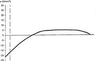
图7代表根据现有技术状态的张力与光纤半径的关系曲线;以及
图8代表根据本发明的张力与光纤半径的关系曲线。
具体实施方式
在图1中示意性表示了一根单模光纤6,光纤6是在将预成型件收缩并且拉制成光纤之后而获得的。可以将单模光纤6当作光传导芯部4,这一光传导芯部4被一个内覆层部分3包围,而内覆层部分3又被一个外套部分1包围。一个衬管例如适合作为外套部分。芯部4的折射率比内覆层部分3和外套部分1的折射率要大,这其中后两部分的折射率实际上是相等的。应该注意到在图1-6中使用的相同标号是彼此一致的。
在图2中示意性表示了单模光纤6的一个具体实施例,这种单模光纤6包括一个光传导芯部4,光传导芯部4被一个内覆层部分3包围,内覆层部分3又被一个缓冲层2包围,而缓冲层2最终被一个外套部分1包围。这种单模光纤6是根据本发明的方法制造的,采用一个石英衬管作为外套部分1,然后是分别利用PCVD工艺沉积缓冲层2、内覆层部分3和最后的芯部4。在石英衬管上沉积完上述各层时执行一个热收缩步骤,之后获得一个预成型件,从预成型件的端部拉制出单模光纤6。
图3中示意性表示了单模光纤6的一个具体实施例,单模光纤6包括被一个中间层5包围的芯部4,中间层5被内覆层部分3包围,内覆层部分3又被一个缓冲层2包围,缓冲层2最终被一个外套部分1包围。图3中示意性表示的单模光纤6是根据与图2所示方式相同的方式制造的。然而,在某些实施例中可以省去图3所示的缓冲层2,结果将内覆层部分3直接沉积在外套部分1上,然后是中间层5,最后是芯部4。但是没有示意性表示出这样的实施例。
在图4中,外套层1设有一个外覆层部分7,在图5和6中也适用。本发明特别值得注意的是,通过为内覆层部分掺杂0.1-8.5wt.%,最好是0.2-2.0wt.%的氟,使单模光纤的芯部经受压缩轴向应力。
图7中表示根据现有技术状态的应力(它随单模光纤的半径r而变化)曲线,光纤包括掺杂有GeO2和F的SiO2构成的芯部和没有掺杂的SiO2构成的覆层部分。用一条垂直虚线表示芯部的位置,因此这就能立即清楚地显示出芯部是处在正应力也就是拉伸应力下。
图8中表示根据本发明的应力(它随单模光纤的半径r而变化)曲线,光纤包括掺杂有GeO2和F的SiO2构成的芯部和根据图5的掺杂有F和GeO2的SiO2构成的另一内覆层部分,其余区域是由没有掺杂的SiO2构成的。同样用一条垂直虚线表示芯部的位置,这就能立即清楚地显示出芯部是处在根据本发明所要求的压缩轴向应力下。
Claims (14)
1.一种单模光纤,其包括光传导芯部(4),围绕该芯部(4)的内覆层部分(3)以及围绕该内覆层部分(3)的外套部分(1),其中芯部(4)的折射率比覆层部分和外套部分区域(3,1)的折射率要大,并且覆层部分和外套部分区域(3,1)的折射率相等,其特征在于,内覆层部分(3)是用包括掺杂在0.1-8.5wt.%范围内的氟的SiO2制成的,这样导致芯部(4)在其整个截面上承受压缩轴向应力,并且内覆层部分(3)还设有增大折射的掺杂质,以获得与外套部分(1)的折射率相等的折射率,其中,采用一石英衬管作为所述外套部分。
2.根据权利要求1所述的单模光纤,其特征在于,内覆层部分(3)内的含氟量处于0.2-2.0wt.%的范围内。
3.根据权利要求1或2所述的单模光纤,其特征在于,在外套部分(1)和内覆层部分(3)之间有缓冲层(2),该缓冲层(2)的折射率比芯部(4)的折射率要低,并且与内覆层部分(3)和外套部分(1)区域的折射率相等。
4.根据权利要求1所述的单模光纤,其特征在于,在芯部(4)和内覆层部分(3)之间有中间层(5),该中间层(5)的折射率比芯部(4)的折射率要低,并且等于内覆层部分(3)和外套部分(1)区域的折射率。
5.根据权利要求1所述的单模光纤,其特征在于,在外套部分(1)的外侧上有外覆层部分(7),该外覆层部分(7)的折射率等于内覆层部分(3)和外套部分(1)区域的折射率。
6.根据权利要求1所述的单模光纤,其特征在于,内覆层部分(3)的厚度在3-21微米的范围内。
7.根据权利要求1所述的单模光纤,其特征在于,芯部(4)是用包括掺杂在0.2-2.0wt.%范围内的氟的SiO2构成的。
8.一种用于制造单模光纤的方法,该光纤包括光传导芯部,围绕该芯部的内覆层部分以及围绕该内覆层部分的外套部分,其中芯部的折射率比内覆层部分和外套部分区域的折射率要大,并且内覆层部分和外套部分区域的折射率相等,根据该方法,用作外套部分的石英衬管被充有一种或多种反应气体,以便分别形成内覆层部分和芯部,然后将衬管收缩并且拉制成单模光纤,其特征在于,内覆层部分(3)是用包括掺杂在0.1-8.5wt.%范围内的氟的SiO2制成的,这样导致芯部(4)在其整个截面上承受压缩轴向应力,其中,采用一石英衬管作为所述外套部分。
9.根据权利要求8所述的方法,其特征在于,内覆层部分(3)内的含氟量处于0.2-2.0wt.%的范围内。
10.根据权利要求8或9所述的方法,其特征在于,在外套部分(1)和内覆层部分(3)之间插入缓冲层(2),该缓冲层(2)的折射率比芯部(4)的折射率要低,并且与内覆层部分(3)和外套部分(1)区域的折射率相等。
11.根据权利要求8所述的方法,其特征在于,在芯部(4)和内覆层部分(3)之间插入中间层(5),该中间层(5)的折射率比芯部(4)的折射率要低,并且等于内覆层部分(3)和外套部分(1)区域的折射率。
12.根据权利要求8所述的方法,其特征在于,在外套部分(1)的外侧上设置外覆层部分(7),该外覆层部分(7)的折射率等于内覆层部分(3)和外套部分(1)区域的折射率。
13.根据权利要求8所述的方法,其特征在于,利用PCVD工艺形成芯部(4)和内覆层部分(3)以及外覆层部分(7)、中间层(5)和/或缓冲层(2)。
14.根据权利要求13所述的方法,其特征在于,PCVD工艺是在等离子体感应条件下执行的。
Applications Claiming Priority (2)
| Application Number | Priority Date | Filing Date | Title |
|---|---|---|---|
| NL1015405A NL1015405C2 (nl) | 2000-06-09 | 2000-06-09 | Single mode optische vezel en werkwijze voor het vervaardigen van een single mode optische vezel. |
| NL1015405 | 2000-06-09 |
Publications (2)
| Publication Number | Publication Date |
|---|---|
| CN1436310A CN1436310A (zh) | 2003-08-13 |
| CN1227547C true CN1227547C (zh) | 2005-11-16 |
Family
ID=19771518
Family Applications (1)
| Application Number | Title | Priority Date | Filing Date |
|---|---|---|---|
| CNB018109144A Expired - Lifetime CN1227547C (zh) | 2000-06-09 | 2001-06-08 | 单模光纤及制造单模光纤的方法 |
Country Status (13)
| Country | Link |
|---|---|
| US (1) | US6754423B2 (zh) |
| EP (1) | EP1287392B1 (zh) |
| JP (1) | JP4808906B2 (zh) |
| KR (1) | KR100789974B1 (zh) |
| CN (1) | CN1227547C (zh) |
| AT (1) | ATE295969T1 (zh) |
| AU (1) | AU2001264412A1 (zh) |
| BR (1) | BRPI0111478B1 (zh) |
| DE (1) | DE60110909T2 (zh) |
| DK (1) | DK1287392T3 (zh) |
| NL (1) | NL1015405C2 (zh) |
| RU (1) | RU2271025C2 (zh) |
| WO (1) | WO2002008811A1 (zh) |
Families Citing this family (14)
| Publication number | Priority date | Publication date | Assignee | Title |
|---|---|---|---|---|
| KR100322131B1 (ko) * | 1999-01-28 | 2002-02-04 | 윤종용 | 오.에이치.차단층을 구비한 광섬유 모재 및 그 제조방법 |
| WO2003059828A1 (fr) * | 2002-01-17 | 2003-07-24 | Sumitomo Electric Industries, Ltd. | Procede et dispositif de fabrication d'un tube de verre |
| US7079749B2 (en) * | 2003-01-27 | 2006-07-18 | Peter Dragic | Waveguide configuration |
| KR101166205B1 (ko) * | 2003-03-21 | 2012-07-18 | 헤라에우스 테네보 게엠베하 | 모재의 제조를 위한 합성 실리카 글래스 튜브, 수직 인발공정을 이용한 합성 실리카 글래스 튜브의 제조방법 및상기 튜브의 이용 |
| JP2005298271A (ja) * | 2004-04-12 | 2005-10-27 | Sumitomo Electric Ind Ltd | 光ファイバの製造方法及び光ファイバ |
| FR2896795B1 (fr) * | 2006-01-27 | 2008-04-18 | Draka Compteq France | Procede de fabrication d'une preforme de fibre optique |
| US7493009B2 (en) * | 2007-05-25 | 2009-02-17 | Baker Hughes Incorporated | Optical fiber with tin doped core-cladding interface |
| US7848604B2 (en) | 2007-08-31 | 2010-12-07 | Tensolite, Llc | Fiber-optic cable and method of manufacture |
| US8315495B2 (en) | 2009-01-30 | 2012-11-20 | Corning Incorporated | Large effective area fiber with Ge-free core |
| US7689085B1 (en) | 2009-01-30 | 2010-03-30 | Corning Incorporated | Large effective area fiber with GE-free core |
| US9052486B2 (en) | 2010-10-21 | 2015-06-09 | Carlisle Interconnect Technologies, Inc. | Fiber optic cable and method of manufacture |
| RU2457519C1 (ru) * | 2010-12-03 | 2012-07-27 | Общество с ограниченной ответственностью "Фиберус" | Интегрально-оптический волновод с активированной сердцевиной, двойной светоотражающей оболочкой и способ его изготовления |
| US8929701B2 (en) | 2012-02-15 | 2015-01-06 | Draka Comteq, B.V. | Loose-tube optical-fiber cable |
| KR102029213B1 (ko) * | 2017-10-30 | 2019-10-07 | 국방과학연구소 | 방사상 전파를 위한 광섬유 팁의 제조방법 |
Family Cites Families (19)
| Publication number | Priority date | Publication date | Assignee | Title |
|---|---|---|---|---|
| JPS5662204A (en) * | 1979-10-25 | 1981-05-28 | Nippon Telegr & Teleph Corp <Ntt> | Optical transmission fiber and its manufacture |
| JPS56121002A (en) * | 1980-02-28 | 1981-09-22 | Nippon Telegr & Teleph Corp <Ntt> | Optical fiber for light transmission and its manufacture |
| US5033815A (en) * | 1979-10-25 | 1991-07-23 | Nippon Telephone & Telegraph | Optical transmission fiber and process for producing the same |
| DE3205345A1 (de) * | 1982-02-15 | 1983-09-01 | Philips Patentverwaltung Gmbh, 2000 Hamburg | "verfahren zur herstellung von fluordotierten lichtleitfasern" |
| EP0131634B1 (en) * | 1983-06-29 | 1988-06-01 | ANT Nachrichtentechnik GmbH | Single-mode w-fibre |
| DE3500672A1 (de) * | 1985-01-11 | 1986-07-17 | Philips Patentverwaltung | Lichtleitfaser mit fluordotierung und verfahren zu deren herstellung |
| FR2650584B1 (fr) * | 1989-08-02 | 1993-12-17 | Cie Generale D Electricite | Procede de fabrication d'une fibre optique a gaine dopee |
| US5044724A (en) * | 1989-12-22 | 1991-09-03 | At&T Bell Laboratories | Method of producing optical fiber, and fiber produced by the method |
| DE4028275A1 (de) * | 1990-09-06 | 1992-03-12 | Kabelmetal Electro Gmbh | Verfahren zur herstellung von glasfaser-lichtwellenleitern mit erhoehter zugfestigkeit |
| US5059229A (en) * | 1990-09-24 | 1991-10-22 | Corning Incorporated | Method for producing optical fiber in a hydrogen atmosphere to prevent attenuation |
| DE19505929C1 (de) * | 1995-02-21 | 1996-03-28 | Heraeus Quarzglas | Optisches Bauteil |
| JP3068013B2 (ja) * | 1995-08-31 | 2000-07-24 | 住友電気工業株式会社 | 分散補償ファイバ |
| US5740297A (en) * | 1995-08-31 | 1998-04-14 | Sumitomo Electric Industries, Ltd. | Dispersion-compensating fiber and method of fabricating the same |
| TW371650B (en) * | 1995-12-04 | 1999-10-11 | Sumitomo Electric Industries | Method for producing an optical fiber quartz glass preform |
| JP3562545B2 (ja) * | 1995-12-04 | 2004-09-08 | 住友電気工業株式会社 | 光ファイバ用ガラス母材の製造方法 |
| JP3503427B2 (ja) * | 1997-06-19 | 2004-03-08 | ソニー株式会社 | 薄膜トランジスタの製造方法 |
| US6131415A (en) * | 1997-06-20 | 2000-10-17 | Lucent Technologies Inc. | Method of making a fiber having low loss at 1385 nm by cladding a VAD preform with a D/d<7.5 |
| JP3337954B2 (ja) * | 1997-09-17 | 2002-10-28 | 株式会社フジクラ | 分散補償光ファイバ |
| FR2792733B1 (fr) * | 1999-04-26 | 2002-01-11 | Cit Alcatel | Preforme comprenant un revetement barriere contre la diffusion d'hydrogene dans la fibre optique fabriquee a partir de cette preforme et procede de preparation d'une telle preforme |
-
2000
- 2000-06-09 NL NL1015405A patent/NL1015405C2/nl not_active IP Right Cessation
-
2001
- 2001-06-08 AT AT01938836T patent/ATE295969T1/de not_active IP Right Cessation
- 2001-06-08 EP EP01938836A patent/EP1287392B1/en not_active Expired - Lifetime
- 2001-06-08 DK DK01938836T patent/DK1287392T3/da active
- 2001-06-08 RU RU2003100093/28A patent/RU2271025C2/ru not_active IP Right Cessation
- 2001-06-08 US US09/876,018 patent/US6754423B2/en not_active Expired - Lifetime
- 2001-06-08 JP JP2002514451A patent/JP4808906B2/ja not_active Expired - Fee Related
- 2001-06-08 BR BRPI0111478A patent/BRPI0111478B1/pt not_active IP Right Cessation
- 2001-06-08 AU AU2001264412A patent/AU2001264412A1/en not_active Abandoned
- 2001-06-08 DE DE60110909T patent/DE60110909T2/de not_active Expired - Lifetime
- 2001-06-08 KR KR1020027016696A patent/KR100789974B1/ko active IP Right Grant
- 2001-06-08 WO PCT/NL2001/000433 patent/WO2002008811A1/en active IP Right Grant
- 2001-06-08 CN CNB018109144A patent/CN1227547C/zh not_active Expired - Lifetime
Also Published As
| Publication number | Publication date |
|---|---|
| US6754423B2 (en) | 2004-06-22 |
| AU2001264412A1 (en) | 2002-02-05 |
| CN1436310A (zh) | 2003-08-13 |
| NL1015405C2 (nl) | 2001-12-12 |
| ATE295969T1 (de) | 2005-06-15 |
| BRPI0111478B1 (pt) | 2015-09-15 |
| BR0111478A (pt) | 2003-07-01 |
| KR100789974B1 (ko) | 2007-12-31 |
| DE60110909T2 (de) | 2006-01-19 |
| EP1287392B1 (en) | 2005-05-18 |
| JP2004505000A (ja) | 2004-02-19 |
| DE60110909D1 (de) | 2005-06-23 |
| DK1287392T3 (da) | 2005-08-15 |
| US20020015570A1 (en) | 2002-02-07 |
| WO2002008811A1 (en) | 2002-01-31 |
| EP1287392A1 (en) | 2003-03-05 |
| KR20030007913A (ko) | 2003-01-23 |
| JP4808906B2 (ja) | 2011-11-02 |
| RU2271025C2 (ru) | 2006-02-27 |
Similar Documents
| Publication | Publication Date | Title |
|---|---|---|
| US6449415B1 (en) | Optical fiber and method of manufacturing the same | |
| CN1227547C (zh) | 单模光纤及制造单模光纤的方法 | |
| CA2565879C (en) | Long wavelength, pure silica core single mode fiber and method of forming the same | |
| CN109839694B (zh) | 一种截止波长位移单模光纤 | |
| JP2007536580A5 (zh) | ||
| CN105911639B (zh) | 一种低衰减单模光纤 | |
| CN107357004B (zh) | 一种低衰减单模光纤及其制备方法 | |
| CN1300609C (zh) | 高性能色散补偿光纤及其制造方法 | |
| CN1818728A (zh) | 模场直径适中的弯曲不敏感光纤 | |
| EP0391742B1 (en) | Image transmitting fiber bundle and manufacturing process thereof | |
| US6530244B1 (en) | Optical fiber preform having OH barrier and fabrication method thereof | |
| EP0763213A1 (en) | Optical waveguide | |
| US20020168162A1 (en) | Step index optical fiber with doped cladding and core, a preform, and a method of fabricating such a fiber | |
| CN1300607C (zh) | 弯曲不敏感光纤及其制备方法 | |
| WO1998000739A1 (en) | Optical fiber with tantalum doped clad | |
| JP2004126141A (ja) | 光ファイバとその製造方法 | |
| CN1317575C (zh) | 一种色散补偿光纤 | |
| CA1298110C (en) | Optical fiber with a high refractive index edge which refracts errant signals from core cladding | |
| JP2002518988A (ja) | タンタルが添加されたクラッドを有する光ファイバ | |
| Gauthier | Exotic Fibres: Multitude of application—specific optical fibres | |
| EP0850431A1 (en) | Optical fiber with tantalum doped clad |
Legal Events
| Date | Code | Title | Description |
|---|---|---|---|
| C06 | Publication | ||
| PB01 | Publication | ||
| C10 | Entry into substantive examination | ||
| SE01 | Entry into force of request for substantive examination | ||
| C14 | Grant of patent or utility model | ||
| GR01 | Patent grant | ||
| CX01 | Expiry of patent term |
Granted publication date: 20051116 |
|
| CX01 | Expiry of patent term |