CN1227547C - Single mode optical fibre, and method for manufacture of same - Google Patents
Single mode optical fibre, and method for manufacture of same Download PDFInfo
- Publication number
- CN1227547C CN1227547C CNB018109144A CN01810914A CN1227547C CN 1227547 C CN1227547 C CN 1227547C CN B018109144 A CNB018109144 A CN B018109144A CN 01810914 A CN01810914 A CN 01810914A CN 1227547 C CN1227547 C CN 1227547C
- Authority
- CN
- China
- Prior art keywords
- refractive index
- coated layer
- core
- internal coated
- layer part
- Prior art date
- Legal status (The legal status is an assumption and is not a legal conclusion. Google has not performed a legal analysis and makes no representation as to the accuracy of the status listed.)
- Expired - Lifetime
Links
Images


Classifications
-
- G—PHYSICS
- G02—OPTICS
- G02B—OPTICAL ELEMENTS, SYSTEMS OR APPARATUS
- G02B6/00—Light guides; Structural details of arrangements comprising light guides and other optical elements, e.g. couplings
- G02B6/02—Optical fibres with cladding with or without a coating
- G02B6/036—Optical fibres with cladding with or without a coating core or cladding comprising multiple layers
- G02B6/03694—Multiple layers differing in properties other than the refractive index, e.g. attenuation, diffusion, stress properties
-
- G—PHYSICS
- G02—OPTICS
- G02B—OPTICAL ELEMENTS, SYSTEMS OR APPARATUS
- G02B6/00—Light guides; Structural details of arrangements comprising light guides and other optical elements, e.g. couplings
- G02B6/02—Optical fibres with cladding with or without a coating
-
- C—CHEMISTRY; METALLURGY
- C03—GLASS; MINERAL OR SLAG WOOL
- C03B—MANUFACTURE, SHAPING, OR SUPPLEMENTARY PROCESSES
- C03B37/00—Manufacture or treatment of flakes, fibres, or filaments from softened glass, minerals, or slags
- C03B37/01—Manufacture of glass fibres or filaments
- C03B37/012—Manufacture of preforms for drawing fibres or filaments
- C03B37/014—Manufacture of preforms for drawing fibres or filaments made entirely or partially by chemical means, e.g. vapour phase deposition of bulk porous glass either by outside vapour deposition [OVD], or by outside vapour phase oxidation [OVPO] or by vapour axial deposition [VAD]
- C03B37/018—Manufacture of preforms for drawing fibres or filaments made entirely or partially by chemical means, e.g. vapour phase deposition of bulk porous glass either by outside vapour deposition [OVD], or by outside vapour phase oxidation [OVPO] or by vapour axial deposition [VAD] by glass deposition on a glass substrate, e.g. by inside-, modified-, plasma-, or plasma modified- chemical vapour deposition [ICVD, MCVD, PCVD, PMCVD], i.e. by thin layer coating on the inside or outside of a glass tube or on a glass rod
- C03B37/01807—Reactant delivery systems, e.g. reactant deposition burners
- C03B37/01815—Reactant deposition burners or deposition heating means
- C03B37/01823—Plasma deposition burners or heating means
- C03B37/0183—Plasma deposition burners or heating means for plasma within a tube substrate
-
- C—CHEMISTRY; METALLURGY
- C03—GLASS; MINERAL OR SLAG WOOL
- C03C—CHEMICAL COMPOSITION OF GLASSES, GLAZES OR VITREOUS ENAMELS; SURFACE TREATMENT OF GLASS; SURFACE TREATMENT OF FIBRES OR FILAMENTS MADE FROM GLASS, MINERALS OR SLAGS; JOINING GLASS TO GLASS OR OTHER MATERIALS
- C03C13/00—Fibre or filament compositions
- C03C13/04—Fibre optics, e.g. core and clad fibre compositions
-
- G—PHYSICS
- G02—OPTICS
- G02B—OPTICAL ELEMENTS, SYSTEMS OR APPARATUS
- G02B6/00—Light guides; Structural details of arrangements comprising light guides and other optical elements, e.g. couplings
- G02B6/02—Optical fibres with cladding with or without a coating
- G02B6/02395—Glass optical fibre with a protective coating, e.g. two layer polymer coating deposited directly on a silica cladding surface during fibre manufacture
-
- G—PHYSICS
- G02—OPTICS
- G02B—OPTICAL ELEMENTS, SYSTEMS OR APPARATUS
- G02B6/00—Light guides; Structural details of arrangements comprising light guides and other optical elements, e.g. couplings
- G02B6/02—Optical fibres with cladding with or without a coating
- G02B6/036—Optical fibres with cladding with or without a coating core or cladding comprising multiple layers
- G02B6/03616—Optical fibres characterised both by the number of different refractive index layers around the central core segment, i.e. around the innermost high index core layer, and their relative refractive index difference
- G02B6/03622—Optical fibres characterised both by the number of different refractive index layers around the central core segment, i.e. around the innermost high index core layer, and their relative refractive index difference having 2 layers only
-
- G—PHYSICS
- G02—OPTICS
- G02B—OPTICAL ELEMENTS, SYSTEMS OR APPARATUS
- G02B6/00—Light guides; Structural details of arrangements comprising light guides and other optical elements, e.g. couplings
- G02B6/02—Optical fibres with cladding with or without a coating
- G02B6/036—Optical fibres with cladding with or without a coating core or cladding comprising multiple layers
- G02B6/03616—Optical fibres characterised both by the number of different refractive index layers around the central core segment, i.e. around the innermost high index core layer, and their relative refractive index difference
- G02B6/03638—Optical fibres characterised both by the number of different refractive index layers around the central core segment, i.e. around the innermost high index core layer, and their relative refractive index difference having 3 layers only
-
- G—PHYSICS
- G02—OPTICS
- G02B—OPTICAL ELEMENTS, SYSTEMS OR APPARATUS
- G02B6/00—Light guides; Structural details of arrangements comprising light guides and other optical elements, e.g. couplings
- G02B6/02—Optical fibres with cladding with or without a coating
- G02B6/036—Optical fibres with cladding with or without a coating core or cladding comprising multiple layers
- G02B6/03616—Optical fibres characterised both by the number of different refractive index layers around the central core segment, i.e. around the innermost high index core layer, and their relative refractive index difference
- G02B6/03661—Optical fibres characterised both by the number of different refractive index layers around the central core segment, i.e. around the innermost high index core layer, and their relative refractive index difference having 4 layers only
-
- G—PHYSICS
- G02—OPTICS
- G02B—OPTICAL ELEMENTS, SYSTEMS OR APPARATUS
- G02B6/00—Light guides; Structural details of arrangements comprising light guides and other optical elements, e.g. couplings
- G02B6/02—Optical fibres with cladding with or without a coating
- G02B6/036—Optical fibres with cladding with or without a coating core or cladding comprising multiple layers
- G02B6/03616—Optical fibres characterised both by the number of different refractive index layers around the central core segment, i.e. around the innermost high index core layer, and their relative refractive index difference
- G02B6/03688—Optical fibres characterised both by the number of different refractive index layers around the central core segment, i.e. around the innermost high index core layer, and their relative refractive index difference having 5 or more layers
-
- C—CHEMISTRY; METALLURGY
- C03—GLASS; MINERAL OR SLAG WOOL
- C03B—MANUFACTURE, SHAPING, OR SUPPLEMENTARY PROCESSES
- C03B2201/00—Type of glass produced
- C03B2201/06—Doped silica-based glasses
- C03B2201/08—Doped silica-based glasses doped with boron or fluorine or other refractive index decreasing dopant
- C03B2201/12—Doped silica-based glasses doped with boron or fluorine or other refractive index decreasing dopant doped with fluorine
-
- C—CHEMISTRY; METALLURGY
- C03—GLASS; MINERAL OR SLAG WOOL
- C03B—MANUFACTURE, SHAPING, OR SUPPLEMENTARY PROCESSES
- C03B2203/00—Fibre product details, e.g. structure, shape
- C03B2203/10—Internal structure or shape details
- C03B2203/22—Radial profile of refractive index, composition or softening point
- C03B2203/24—Single mode [SM or monomode]
Abstract
The present invention relates to a method for the manufacture of a single mode optical fibre comprising a light-conductive core portion (4), an internal cladding portion (3) surrounding said core portion and a jacketing portion (1) surrounding said internal cladding portion, in which the refractive index of the core portion is larger than those of the cladding and jacketing portion areas, and in which the refractive indices of the cladding and jacketing portion areas are practically equal.
Description
Technical field
The present invention relates to a kind of manufacture method of single-mode fiber, this optical fiber comprises a light conduction core, internal coated layer part around above-mentioned core, and around above-mentioned internal coated layer overcoat part partly, wherein the refractive index ratio coating of core and the subregional refractive index of outer race section want big, and coating is in fact equal with the subregional refractive index of outer race section, by this method, can be full of as overcoat quartz liner partly with one or more reacting gas in inside, so that form internal coated layer part and core respectively, shrinking this set then has the bushing pipe of layer and is drawn into single-mode fiber.In addition, the invention still further relates to a kind of single-mode fiber, it comprises a light conduction core, around a coating part of above-mentioned core, and around above-mentioned internal coated layer overcoat part partly.
Background technology
Such optical fiber is known and is mainly used in the telecommunication technology field.For example can be referring to european patent application 0127227 and United States Patent (USP) 5,242, No. 476 and 5,838, No. 866.Term used herein " single mode " is known in those skilled in the art, need not further explanation.Because the characteristic of its low decay and scattering, this optical fiber is particularly suitable for being used for constructing the remote data link that often will cross over thousands of kilometers, on distance far away like this, if the transmission of light signal is to finish with quantity middle amplifier station seldom, is vital with the accumulating signal damage control in the optical fiber in minimum.On the 1550nm transmission wavelength that telecommunications industry is used always, require the overall attenuation in this optical fiber can not surpass 0.25dB/km usually, preferably be no more than 0.2dB/km.
Although the optical fiber of making can satisfy all these requirements about allowing to decay at present, often will find that through after a while some optical fiber presents tangible decay and increases.This phenomenon of further investigation discovery can be oozed out gradually on every side from optical fiber owing to hydrogen and be entered optical fiber, can form gatherings such as SiH and SiOH subsequently in optical fiber.These compounds present very strong infrared ray-absorbable, damping peak be about 1530 and the wavelength of 1385nm on.
European patent application 0477435 discloses a kind of method that solves attenuation problem due to this hydrogen.According to this method, the optical fiber with fusing in manufacture process is exposed to hydrogeneous gas fully, just guarantees that fault of construction points all in the optical fiber is all occupied by hydrogen atom actual before making optical fiber.Yet the shortcoming of this known method is that it cures the symptoms, not the disease to the decay due to the hydrogen.In addition, this known method can make manufacturing process complicated, and brings extra pollution risk because of having adopted hydrogen to know from experience to finished product optical fiber.
United States Patent (USP) 5,090,979 disclose a kind of method of making optical fiber, it comprises a pure silicon dioxide core successively, the silica outer layer of a doped with fluorine, the silicon dioxide liner bottom of doped with fluorine, and a carrier layer of pure silicon dioxide, and the refractive index of the refractive index of core and carrier layer is in fact equal.
United States Patent (USP) 5,033,815 disclose a kind of multimode optical fiber, and this optical fiber has obviously different with single-mode fiber of the present invention.In addition, the disclosed this multimode optical fiber of the document comprises a GeO successively
2-or Sb
2O
3The core of-doping, the coating portion that F-mixes also has a TiO at last
2-overcoat the part of mixing, wherein the refractive index ratio coating of core and the subregional refractive index of outer race section want high, and the refractive index of overcoat part will be starkly lower than the refractive index of coating portion, and this index distribution and distribution of the present invention are completely different.The data of relevant compressional axis to stress are not disclosed in the above-mentioned document.
European patent application 0762159 discloses a kind of scatter compensation type optical fiber, and it comprises at least the GeO with 10mol% successively
2A core and a coating portion, coating portion comprises the first fluorine doping coating portion, the second chlorine doping coating portion and trichlorine or fluorine doping coating portion.The doping of three coating portions is chosen such that make its glass viscosity, so just can in pulling process, adopts lower temperature drawing the viscosity that moment is lower than pure silicon dioxide glass.The document does not disclose the data of relevant compressional axis to stress.
Summary of the invention
Therefore the manufacture method that the purpose of this invention is to provide a kind of single-mode fiber makes on the 1550nm wavelength enough lowly by the decay due to the hydrogen, has only 0.25dB/km at most to guarantee the overall attenuation on this wavelength, preferably has only 0.2dB/km at most.
As described in preface, realized this purpose according to the present invention, this is owing to be to have used the present invention to make the method for single-mode fiber, it is characterized in that, internal coated layer partly is the SiO that is entrained in the fluorine in the 0.1-8.5wt.% scope with comprising
2Make, can make core on its whole cross section, bear a compression axial stress like this.
The inventor thinks that producing axial compression in fiber cores can prevent above-mentioned defective, so just can significantly reduce by the decay due to the hydrogen.According to the present invention, be formed on fault of construction in the silica core easily owing to have axial tensile force in the fiber cores, be present in axial compression in the fiber cores and can get rid of basically and this defective occurs, so just can significantly reduce the decay due to the hydrogen.
The inventor did many experiments, made preformed member according to the following steps, partly was SiO with the fluorine that comprises doping for the inside surface of bushing pipe provides the internal coated layer part of a silicon dioxide, this coating
2Constitute, and second doped layer of silicon dioxide, the refractive index of the refractive index ratio internal coated layer part of this second layer wants high, and forms final fiber core.This bushing pipe that is provided with core and internal coated layer part is heated continuously, make a rod through shrinking process, finally the end points from a fusing of rod is drawn into required optical fiber.
The invention provides a kind of method that is used to make single-mode fiber, this optical fiber comprises light conduction core, around the internal coated layer part of this core and around this internal coated layer overcoat part partly, wherein the refractive index ratio internal coated layer of core part and the subregional refractive index of outer race section want big, and internal coated layer part and the subregional refractive index of outer race section equate, according to this method, quartz liner as the overcoat part is filled with one or more reacting gas, so that form internal coated layer part and core respectively, then bushing pipe is shunk and be drawn into single-mode fiber, it is characterized in that internal coated layer partly is the SiO that is entrained in the fluorine in the 0.1-8.5wt.% scope with comprising
2Make, cause core on its whole cross section, to bear the compression axial stress like this, wherein, adopt a quartz liner as described overcoat part.
According to the present invention, the internal coated layer part fluorine in the 0.1-8.5wt.% scope that preferably mixes is best with 0.2-2.0wt.%.Do not wish that fluorine mixes above 8.5wt.%, otherwise can when these layers of deposition, have problems.Fluorine content can not play the obvious effect that required compression axial stress is provided less than 0.1wt.% in core.Very low if desired attenuation losses, the maximum doping of 2.0wt.% are best, and the increase of Rayleigh scattering has adverse effect to attenuation losses.Experimental result shows that the part of internal coated layer part also can be as the light path of the light that transmits within fiber core.
In the internal coated layer part, adopt fluorine to mix and to reduce the refractive index of this one deck.In order to regulate the refractive index of this reduction, preferably allow the subregional refractive index of the as many as outer race section of this refractive index, for partly providing so-called refraction, internal coated layer increases dopant material, and for example be P
2O
5, TiO
2, ZrO
2, SnO
2, GeO
2, N or Al
2O
3, or one or more these type of combination of compounds.
Some embodiment according to the inventive method, particularly preferably be between overcoat part and internal coated layer part and insert a cushion, the refractive index of the refractive index ratio core of this cushion is low, and in fact equates with coating part and the subregional refractive index of outer race section.
If the optical quality of overcoat part is poor, that is to say that overcoat partly contains impurity, just need this cushion especially.Make preformed member and be drawn into subsequently with preformed member in the continuous heat process of optical fiber in contraction, this impurity can infiltrate the light conducting part of optical fiber, thereby causes the altitude decay.Adopt cushion can prevent that impurity from arriving the light conducting part of optical fiber.
A specific embodiment according to the inventive method, also preferably between core and internal coated layer part, inserted a middle layer, the refractive index of the refractive index ratio core in this middle layer is low, and as many as internal coated layer part and the subregional refractive index of outer race section.
It is directly to carry out in the layer of core that light in the single-mode fiber conducts some.If this one deck mixes too much, will obviously increase the effect of Rayleigh scattering, cause decay to increase.Yet, be subjected to required compression axial stress in order to make core, may need high doped.Thereby preferably insert a low-doped middle layer and prevent the possible negative effect of excessive Rayleigh scattering.
In the optical fiber of making, the thickness of internal coated layer part is the 3-21 micron preferably.
Required bed thickness depends on the doping in the layer.Test demonstrates less than 3 microns layer thickness deficiency so that core requirement according to the present invention is subjected to required compression axial stress.The upper limit of the maximum bed thickness of internal coated layer part mainly is to be determined by the processibility of the preformed member that finally is drawn into optical fiber.
In a particular embodiment, what is also needed is, being provided with one or more doping light conduction cores is by SiO
2Constitute, comprise fluorine and one or more dopings of being entrained in the 0.2-2wt.% scope, guarantee that core can reach according to refractive index of the presently claimed invention, the refractive index height of the refractive index ratio coating part of this core, this doping for example can comprise P
2O
5, TiO
2, ZrO
2, SnO
2, GeO
2, N and Al
2O
3, or one or more these type of combination of compounds.
According to a specific embodiment, preferably, the preformed member that comprises core, internal coated layer part and overcoat part provides a buffering and/or middle layer for replenishing, and on the outside surface of overcoat part, provide an extra play, for example be the form of taking glass tube, or the one deck that utilizes outside CVD technology to apply.
According to the present invention, adopt chemical vapor deposition process, particularly adopt a kind of PCVD technology of preferably responding to form above-mentioned core and internal coated layer part and presumable centre and/or cushion by plasma.Because the axial length of conventional bushing pipe is than the big manyfold of its diameter, it is very difficult controllably depositing the layer of even material on the inside surface of this bushing pipe according to the depositing operation such as routines such as sputtering sedimentation or laser ablation deposition.The chemical evapn that applies in PCVD embodiment can effectively be distributed to the total length of bushing pipe inside surface, so just can form well-proportioned deposition on inwall.In addition, adopt PVCD technology might be when each layer of deposition the control doped level, so just can successfully deposit core and internal coated layer partly and the centre and/or the cushion that may also have with this technology.
According to a specific embodiment of the inventive method, preferably on the outside of overcoat part, the outer covering layer part is set, the refractive index of this outer covering layer part equals internal coated layer part and the subregional refractive index of outer race section.
The invention further relates to a kind of single-mode fiber, it comprises light conduction core, around the internal coated layer part of this core and around this internal coated layer overcoat part partly, wherein the refractive index ratio coating of core part and the subregional refractive index of outer race section want big, and coating part and the subregional refractive index of outer race section equate, it is characterized in that internal coated layer partly is the SiO that is entrained in the fluorine in the 0.1-8.5wt.% scope with comprising
2Make, cause core on its whole cross section, to bear the compression axial stress like this, and internal coated layer part also is provided with the doping that increases refraction, with the refractive index that obtains to equate with overcoat refractive index partly, wherein, adopt a quartz liner as described overcoat part.
In one embodiment, best is that the interior fluorinated volume of internal coated layer part is in the scope of 0.2-2.0wt.%.
In a specific embodiment, further preferably, single-mode fiber is to constitute like this, inserts a middle layer between core and internal coated layer part, the refractive index of the refractive index ratio core in this middle layer is low, and as many as internal coated layer part and the subregional refractive index of outer race section.
In addition, in a specific embodiment of single-mode fiber of the present invention, preferably between overcoat part and internal coated layer part a cushion is arranged, the refractive index of the refractive index ratio core of this cushion is low, and in fact equates with internal coated layer part and the subregional refractive index of outer race section.
In addition, in certain embodiments, on the outside of overcoat part, an outer covering layer part is arranged preferably.
In addition, in one embodiment, on the outside of overcoat part, the outer covering layer part is arranged, as many as internal coated layer part of the refractive index of this outer covering layer part and the subregional refractive index of outer race section.
Below to utilize many accompanying drawings to explain the present invention, the purpose that these accompanying drawings are only used for explaining, and do not really want protection scope of the present invention is constituted any restriction.
Description of drawings
Fig. 1 represents an embodiment according to single-mode fiber of the present invention;
Fig. 2 represents a specific embodiment according to single-mode fiber of the present invention, has settled cushion therein;
Fig. 3 represents a specific embodiment according to single-mode fiber of the present invention, is provided with a middle layer therein;
Fig. 4-6 respectively corresponding Fig. 1-3, yet outer race section wherein is arranged with an outer covering layer part;
Fig. 7 representative is according to the tension force of prior art state and the relation curve of fiber radius; And
Fig. 8 representative is according to the relation curve of tension force of the present invention and fiber radius.
Embodiment
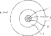
Schematically shown a single-mode fiber 6 in Fig. 1, optical fiber 6 is after shrinking preformed member and being drawn into optical fiber and obtain.Single-mode fiber 6 can be used as light conduction core 4, this light conduction core 4 is surrounded by an internal coated layer part 3, and internal coated layer part 3 is surrounded by an overcoat part 1.A bushing pipe for example is suitable as the overcoat part.It is big that the refractive index ratio internal coated layer part 3 of core 4 and the refractive index of overcoat part 1 are wanted, and this wherein back two-part refractive index is actually equal.Should be noted that the same numeral that uses is consistent each other in Fig. 1-6.
In Fig. 2, schematically shown a specific embodiment of single-mode fiber 6, this single-mode fiber 6 comprises a light conduction core 4, light conduction core 4 is surrounded by an internal coated layer part 3, and internal coated layer part 3 is surrounded by a cushion 2 again, and cushion 2 is finally surrounded by an overcoat part 1.This single-mode fiber 6 is made according to the method for the present invention, adopts a quartz liner as overcoat part 1, is to utilize PCVD process deposits cushion 2, internal coated layer part 3 and last core 4 respectively then.Carry out a thermal shrinkage step when on quartz liner, having deposited above-mentioned each layer, obtain a preformed member afterwards, draw out single-mode fiber 6 from the end of preformed member.
Schematically shown a specific embodiment of single-mode fiber 6 among Fig. 3, single-mode fiber 6 comprises the core 4 that is surrounded by a middle layer 5, middle layer 5 is surrounded by internal coated layer part 3, and internal coated layer part 3 is surrounded by a cushion 2 again, and cushion 2 is finally surrounded by an overcoat part 1.The single-mode fiber 6 that schematically shows among Fig. 3 is to make according to the mode identical with mode shown in Figure 2.Yet, can save cushion shown in Figure 32 in certain embodiments, the result directly is deposited on internal coated layer part 3 on the overcoat part 1, is middle layer 5 then, is core 4 at last.But do not schematically show out such embodiment.
In Fig. 4, sheathcoat 1 is provided with an outer covering layer part 7, also is suitable in Fig. 5 and 6.The present invention it should be noted that especially preferably the fluorine of 0.2-2.0wt.% makes the core of single-mode fiber stand to compress axial stress by the 0.1-8.5wt.% that partly mixes for internal coated layer.
Expression is according to stress (it changes with the radius r of the single-mode fiber) curve of prior art state among Fig. 7, and optical fiber comprises the SiO that is doped with GeO2 and F
2The core that constitutes the and not have SiO of doping
2The coating part that constitutes.Represent the position of core with a vertical dotted line, thus this just to clearly show core immediately be to be in normal stress just under the drawing stress.
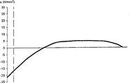
Expression is according to stress of the present invention (it changes with the radius r of single-mode fiber) curve among Fig. 8, and optical fiber comprises the SiO that is doped with GeO2 and F
2The core that constitutes and be doped with F and GeO according to Fig. 5
2SiO
2Another internal coated layer part that constitutes, all the other zones are the SiO that mix by not having
2Constitute.Represent the position of core equally with a vertical dotted line, this just can clearly show core immediately is to be in according under the compression axial stress of the presently claimed invention.
Claims (14)
1. single-mode fiber, it comprises light conduction core (4), around internal coated layer part (3) of this core (4) and the overcoat part (1) that centers on this internal coated layer part (3), wherein the refractive index ratio coating of core (4) part and outer race section subregion (3,1) it is big that refractive index is wanted, and coating part and outer race section subregion (3,1) refractive index equates, it is characterized in that, internal coated layer part (3) is with comprising that the SiO2 that is entrained in the fluorine in the 0.1-8.5wt.% scope makes, cause core (4) on its whole cross section, to bear the compression axial stress like this, and internal coated layer part (3) also is provided with the doping that increases refraction, refractive index to obtain to equate with the refractive index of overcoat part (1) wherein, adopts a quartz liner as described overcoat part.
2. single-mode fiber according to claim 1 is characterized in that, the fluorinated volume in the internal coated layer part (3) is in the scope of 0.2-2.0wt.%.
3. single-mode fiber according to claim 1 and 2, it is characterized in that, between overcoat part (1) and internal coated layer part (3), cushion (2) is arranged, the refractive index of the refractive index ratio core (4) of this cushion (2) is low, and equates with the refractive index in internal coated layer part (3) and overcoat part (1) zone.
4. single-mode fiber according to claim 1, it is characterized in that, between core (4) and internal coated layer part (3) middle layer (5) is arranged, the refractive index of the refractive index ratio core (4) of this middle layer (5) is low, and equals the refractive index in internal coated layer part (3) and overcoat part (1) zone.
5. single-mode fiber according to claim 1 is characterized in that, outer covering layer part (7) is arranged on the outside of overcoat part (1), and the refractive index of this outer covering layer part (7) equals the refractive index in internal coated layer part (3) and overcoat part (1) zone.
6. single-mode fiber according to claim 1 is characterized in that, the thickness of internal coated layer part (3) is in the scope of 3-21 micron.
7. single-mode fiber according to claim 1 is characterized in that, core (4) is with comprising that the SiO2 that is entrained in the fluorine in the 0.2-2.0wt.% scope constitutes.
8. method that is used to make single-mode fiber, this optical fiber comprises light conduction core, around the internal coated layer part of this core and around this internal coated layer overcoat part partly, wherein the refractive index ratio internal coated layer of core part and the subregional refractive index of outer race section want big, and internal coated layer part and the subregional refractive index of outer race section equate, according to this method, quartz liner as the overcoat part is filled with one or more reacting gas, so that form internal coated layer part and core respectively, then bushing pipe is shunk and be drawn into single-mode fiber, it is characterized in that, internal coated layer part (3) is with comprising that the SiO2 that is entrained in the fluorine in the 0.1-8.5wt.% scope makes, cause core (4) on its whole cross section, to bear the compression axial stress like this, wherein, adopt a quartz liner as described overcoat part.
9. method according to claim 8 is characterized in that, the fluorinated volume in the internal coated layer part (3) is in the scope of 0.2-2.0wt.%.
10. according to Claim 8 or 9 described methods, it is characterized in that, between overcoat part (1) and internal coated layer part (3), insert cushion (2), the refractive index of the refractive index ratio core (4) of this cushion (2) is low, and equates with the refractive index in internal coated layer part (3) and overcoat part (1) zone.
11. method according to claim 8, it is characterized in that, insert middle layer (5) between core (4) and internal coated layer part (3), the refractive index of the refractive index ratio core (4) of this middle layer (5) is low, and equals the refractive index in internal coated layer part (3) and overcoat part (1) zone.
12. method according to claim 8 is characterized in that, outer covering layer part (7) is set on the outside of overcoat part (1), the refractive index of this outer covering layer part (7) equals the refractive index in internal coated layer part (3) and overcoat part (1) zone.
13. method according to claim 8 is characterized in that, utilizes PCVD technology to form core (4) and internal coated layer part (3) and outer covering layer part (7), middle layer (5) and/or cushion (2).
14. method according to claim 13 is characterized in that, PCVD technology is carried out under the plasma sensed conditions.
Applications Claiming Priority (2)
| Application Number | Priority Date | Filing Date | Title |
|---|---|---|---|
| NL1015405 | 2000-06-09 | ||
| NL1015405A NL1015405C2 (en) | 2000-06-09 | 2000-06-09 | Single mode optical fiber and method of manufacturing a single mode optical fiber. |
Publications (2)
| Publication Number | Publication Date |
|---|---|
| CN1436310A CN1436310A (en) | 2003-08-13 |
| CN1227547C true CN1227547C (en) | 2005-11-16 |
Family
ID=19771518
Family Applications (1)
| Application Number | Title | Priority Date | Filing Date |
|---|---|---|---|
| CNB018109144A Expired - Lifetime CN1227547C (en) | 2000-06-09 | 2001-06-08 | Single mode optical fibre, and method for manufacture of same |
Country Status (13)
| Country | Link |
|---|---|
| US (1) | US6754423B2 (en) |
| EP (1) | EP1287392B1 (en) |
| JP (1) | JP4808906B2 (en) |
| KR (1) | KR100789974B1 (en) |
| CN (1) | CN1227547C (en) |
| AT (1) | ATE295969T1 (en) |
| AU (1) | AU2001264412A1 (en) |
| BR (1) | BRPI0111478B1 (en) |
| DE (1) | DE60110909T2 (en) |
| DK (1) | DK1287392T3 (en) |
| NL (1) | NL1015405C2 (en) |
| RU (1) | RU2271025C2 (en) |
| WO (1) | WO2002008811A1 (en) |
Families Citing this family (14)
| Publication number | Priority date | Publication date | Assignee | Title |
|---|---|---|---|---|
| KR100322131B1 (en) * | 1999-01-28 | 2002-02-04 | 윤종용 | Optical fiber preform having OH barrier and method of fabricating the same |
| US20040129030A1 (en) * | 2002-01-17 | 2004-07-08 | Haruyoshi Tanada | Method and device for manufacturing glass tube |
| US7079749B2 (en) * | 2003-01-27 | 2006-07-18 | Peter Dragic | Waveguide configuration |
| WO2004083141A1 (en) * | 2003-03-21 | 2004-09-30 | Heraeus Tenevo Gmbh | Synthetic silica glass tube for the production of a preform, method for producing the same in a vertical drawing process and use of said tube |
| JP2005298271A (en) * | 2004-04-12 | 2005-10-27 | Sumitomo Electric Ind Ltd | Method of manufacturing optical fiber, and opticalcal fiber |
| FR2896795B1 (en) * | 2006-01-27 | 2008-04-18 | Draka Compteq France | PROCESS FOR PRODUCING AN OPTICAL FIBER PREFORM |
| US7493009B2 (en) * | 2007-05-25 | 2009-02-17 | Baker Hughes Incorporated | Optical fiber with tin doped core-cladding interface |
| US7848604B2 (en) | 2007-08-31 | 2010-12-07 | Tensolite, Llc | Fiber-optic cable and method of manufacture |
| US8315495B2 (en) | 2009-01-30 | 2012-11-20 | Corning Incorporated | Large effective area fiber with Ge-free core |
| US7689085B1 (en) | 2009-01-30 | 2010-03-30 | Corning Incorporated | Large effective area fiber with GE-free core |
| US9052486B2 (en) | 2010-10-21 | 2015-06-09 | Carlisle Interconnect Technologies, Inc. | Fiber optic cable and method of manufacture |
| RU2457519C1 (en) * | 2010-12-03 | 2012-07-27 | Общество с ограниченной ответственностью "Фиберус" | Integral optical waveguide with activated core, double light-reflective shell and its manufacture method |
| US8929701B2 (en) | 2012-02-15 | 2015-01-06 | Draka Comteq, B.V. | Loose-tube optical-fiber cable |
| KR102029213B1 (en) * | 2017-10-30 | 2019-10-07 | 국방과학연구소 | Fabrication method of micro-fiber concave tip for radial wave propagation |
Family Cites Families (19)
| Publication number | Priority date | Publication date | Assignee | Title |
|---|---|---|---|---|
| JPS5662204A (en) * | 1979-10-25 | 1981-05-28 | Nippon Telegr & Teleph Corp <Ntt> | Optical transmission fiber and its manufacture |
| JPS56121002A (en) * | 1980-02-28 | 1981-09-22 | Nippon Telegr & Teleph Corp <Ntt> | Optical fiber for light transmission and its manufacture |
| US5033815A (en) * | 1979-10-25 | 1991-07-23 | Nippon Telephone & Telegraph | Optical transmission fiber and process for producing the same |
| DE3205345A1 (en) * | 1982-02-15 | 1983-09-01 | Philips Patentverwaltung Gmbh, 2000 Hamburg | "METHOD FOR THE PRODUCTION OF FLUOREDOTED LIGHT-CONDUCTING FIBERS" |
| DE3376884D1 (en) * | 1983-06-29 | 1988-07-07 | Ant Nachrichtentech | SINGLE MODE W-FIBER |
| DE3500672A1 (en) * | 1985-01-11 | 1986-07-17 | Philips Patentverwaltung | LIGHT-GUIDE FIBER WITH FLUOROUS DOPING AND METHOD FOR THE PRODUCTION THEREOF |
| FR2650584B1 (en) * | 1989-08-02 | 1993-12-17 | Cie Generale D Electricite | METHOD FOR MANUFACTURING OPTICAL FIBER WITH DOPED SHEATH |
| US5044724A (en) * | 1989-12-22 | 1991-09-03 | At&T Bell Laboratories | Method of producing optical fiber, and fiber produced by the method |
| DE4028275A1 (en) * | 1990-09-06 | 1992-03-12 | Kabelmetal Electro Gmbh | METHOD FOR THE PRODUCTION OF FIBERGLASS FIBER OPTICS WITH INCREASED STRENGTH |
| US5059229A (en) * | 1990-09-24 | 1991-10-22 | Corning Incorporated | Method for producing optical fiber in a hydrogen atmosphere to prevent attenuation |
| DE19505929C1 (en) * | 1995-02-21 | 1996-03-28 | Heraeus Quarzglas | Low attenuation optical component e.g.. fibre or preform |
| CN1087432C (en) * | 1995-08-31 | 2002-07-10 | 住友电气工业株式会社 | Dispersion-compensating fiber and method of fabricating the same |
| JP3068013B2 (en) * | 1995-08-31 | 2000-07-24 | 住友電気工業株式会社 | Dispersion compensating fiber |
| JP3562545B2 (en) * | 1995-12-04 | 2004-09-08 | 住友電気工業株式会社 | Method for producing glass preform for optical fiber |
| TW371650B (en) * | 1995-12-04 | 1999-10-11 | Sumitomo Electric Industries | Method for producing an optical fiber quartz glass preform |
| JP3503427B2 (en) * | 1997-06-19 | 2004-03-08 | ソニー株式会社 | Method for manufacturing thin film transistor |
| US6131415A (en) * | 1997-06-20 | 2000-10-17 | Lucent Technologies Inc. | Method of making a fiber having low loss at 1385 nm by cladding a VAD preform with a D/d<7.5 |
| JP3337954B2 (en) * | 1997-09-17 | 2002-10-28 | 株式会社フジクラ | Dispersion compensating optical fiber |
| FR2792733B1 (en) * | 1999-04-26 | 2002-01-11 | Cit Alcatel | PREFORM COMPRISING A BARRIER COATING AGAINST HYDROGEN DIFFUSION IN THE OPTICAL FIBER MANUFACTURED FROM THIS PREFORM AND PROCESS FOR PREPARING SUCH A PREFORM |
-
2000
- 2000-06-09 NL NL1015405A patent/NL1015405C2/en not_active IP Right Cessation
-
2001
- 2001-06-08 WO PCT/NL2001/000433 patent/WO2002008811A1/en active IP Right Grant
- 2001-06-08 RU RU2003100093/28A patent/RU2271025C2/en not_active IP Right Cessation
- 2001-06-08 JP JP2002514451A patent/JP4808906B2/en not_active Expired - Fee Related
- 2001-06-08 DE DE60110909T patent/DE60110909T2/en not_active Expired - Lifetime
- 2001-06-08 KR KR1020027016696A patent/KR100789974B1/en active IP Right Grant
- 2001-06-08 BR BRPI0111478A patent/BRPI0111478B1/en not_active IP Right Cessation
- 2001-06-08 EP EP01938836A patent/EP1287392B1/en not_active Expired - Lifetime
- 2001-06-08 DK DK01938836T patent/DK1287392T3/en active
- 2001-06-08 US US09/876,018 patent/US6754423B2/en not_active Expired - Lifetime
- 2001-06-08 CN CNB018109144A patent/CN1227547C/en not_active Expired - Lifetime
- 2001-06-08 AT AT01938836T patent/ATE295969T1/en not_active IP Right Cessation
- 2001-06-08 AU AU2001264412A patent/AU2001264412A1/en not_active Abandoned
Also Published As
| Publication number | Publication date |
|---|---|
| CN1436310A (en) | 2003-08-13 |
| EP1287392A1 (en) | 2003-03-05 |
| US6754423B2 (en) | 2004-06-22 |
| ATE295969T1 (en) | 2005-06-15 |
| US20020015570A1 (en) | 2002-02-07 |
| AU2001264412A1 (en) | 2002-02-05 |
| WO2002008811A1 (en) | 2002-01-31 |
| RU2271025C2 (en) | 2006-02-27 |
| DK1287392T3 (en) | 2005-08-15 |
| JP4808906B2 (en) | 2011-11-02 |
| BR0111478A (en) | 2003-07-01 |
| EP1287392B1 (en) | 2005-05-18 |
| KR20030007913A (en) | 2003-01-23 |
| JP2004505000A (en) | 2004-02-19 |
| BRPI0111478B1 (en) | 2015-09-15 |
| DE60110909T2 (en) | 2006-01-19 |
| DE60110909D1 (en) | 2005-06-23 |
| NL1015405C2 (en) | 2001-12-12 |
| KR100789974B1 (en) | 2007-12-31 |
Similar Documents
| Publication | Publication Date | Title |
|---|---|---|
| US6449415B1 (en) | Optical fiber and method of manufacturing the same | |
| CN1227547C (en) | Single mode optical fibre, and method for manufacture of same | |
| CA2565879C (en) | Long wavelength, pure silica core single mode fiber and method of forming the same | |
| EP2584389B1 (en) | Bend insensitive fiber | |
| CN109839694B (en) | Single mode fiber with cut-off wavelength displacement | |
| JP2007536580A5 (en) | ||
| CN105911639B (en) | A kind of low decaying single mode optical fiber | |
| CN107357004B (en) | Low-attenuation single-mode optical fiber and preparation method thereof | |
| CN1818728A (en) | Bending non-sensitive fibre optical with moderate modulus filed diameter | |
| EP0391742B1 (en) | Image transmitting fiber bundle and manufacturing process thereof | |
| CN1492246A (en) | High performance chromatic dispersion compensation optical fiber and its producing method | |
| US6530244B1 (en) | Optical fiber preform having OH barrier and fabrication method thereof | |
| EP0763213A1 (en) | Optical waveguide | |
| US6904213B2 (en) | Step index optical fiber with doped cladding and core, a preform, and a method of fabricating such a fiber | |
| CN1300607C (en) | Bending insensitive optical fiber and preparing method thereof | |
| WO1998000739A1 (en) | Optical fiber with tantalum doped clad | |
| JP2004126141A (en) | Optical fiber and its manufacturing method | |
| CN1317575C (en) | Dispersion compensation optical fibre | |
| CA1298110C (en) | Optical fiber with a high refractive index edge which refracts errant signals from core cladding | |
| JP2002518988A (en) | Optical fiber with tantalum-doped cladding | |
| EP0850431A1 (en) | Optical fiber with tantalum doped clad |
Legal Events
| Date | Code | Title | Description |
|---|---|---|---|
| C06 | Publication | ||
| PB01 | Publication | ||
| C10 | Entry into substantive examination | ||
| SE01 | Entry into force of request for substantive examination | ||
| C14 | Grant of patent or utility model | ||
| GR01 | Patent grant | ||
| CX01 | Expiry of patent term |
Granted publication date: 20051116 |
|
| CX01 | Expiry of patent term |