JP4808906B2 - Single-mode optical fiber and single-mode optical fiber manufacturing method - Google Patents
Single-mode optical fiber and single-mode optical fiber manufacturing method Download PDFInfo
- Publication number
- JP4808906B2 JP4808906B2 JP2002514451A JP2002514451A JP4808906B2 JP 4808906 B2 JP4808906 B2 JP 4808906B2 JP 2002514451 A JP2002514451 A JP 2002514451A JP 2002514451 A JP2002514451 A JP 2002514451A JP 4808906 B2 JP4808906 B2 JP 4808906B2
- Authority
- JP
- Japan
- Prior art keywords
- refractive index
- inner cladding
- optical fiber
- jacket
- mode optical
- Prior art date
- Legal status (The legal status is an assumption and is not a legal conclusion. Google has not performed a legal analysis and makes no representation as to the accuracy of the status listed.)
- Expired - Fee Related
Links
Images


Classifications
-
- G—PHYSICS
- G02—OPTICS
- G02B—OPTICAL ELEMENTS, SYSTEMS OR APPARATUS
- G02B6/00—Light guides; Structural details of arrangements comprising light guides and other optical elements, e.g. couplings
- G02B6/02—Optical fibres with cladding with or without a coating
- G02B6/036—Optical fibres with cladding with or without a coating core or cladding comprising multiple layers
- G02B6/03694—Multiple layers differing in properties other than the refractive index, e.g. attenuation, diffusion, stress properties
-
- G—PHYSICS
- G02—OPTICS
- G02B—OPTICAL ELEMENTS, SYSTEMS OR APPARATUS
- G02B6/00—Light guides; Structural details of arrangements comprising light guides and other optical elements, e.g. couplings
- G02B6/02—Optical fibres with cladding with or without a coating
-
- C—CHEMISTRY; METALLURGY
- C03—GLASS; MINERAL OR SLAG WOOL
- C03B—MANUFACTURE, SHAPING, OR SUPPLEMENTARY PROCESSES
- C03B37/00—Manufacture or treatment of flakes, fibres, or filaments from softened glass, minerals, or slags
- C03B37/01—Manufacture of glass fibres or filaments
- C03B37/012—Manufacture of preforms for drawing fibres or filaments
- C03B37/014—Manufacture of preforms for drawing fibres or filaments made entirely or partially by chemical means, e.g. vapour phase deposition of bulk porous glass either by outside vapour deposition [OVD], or by outside vapour phase oxidation [OVPO] or by vapour axial deposition [VAD]
- C03B37/018—Manufacture of preforms for drawing fibres or filaments made entirely or partially by chemical means, e.g. vapour phase deposition of bulk porous glass either by outside vapour deposition [OVD], or by outside vapour phase oxidation [OVPO] or by vapour axial deposition [VAD] by glass deposition on a glass substrate, e.g. by inside-, modified-, plasma-, or plasma modified- chemical vapour deposition [ICVD, MCVD, PCVD, PMCVD], i.e. by thin layer coating on the inside or outside of a glass tube or on a glass rod
- C03B37/01807—Reactant delivery systems, e.g. reactant deposition burners
- C03B37/01815—Reactant deposition burners or deposition heating means
- C03B37/01823—Plasma deposition burners or heating means
- C03B37/0183—Plasma deposition burners or heating means for plasma within a tube substrate
-
- C—CHEMISTRY; METALLURGY
- C03—GLASS; MINERAL OR SLAG WOOL
- C03C—CHEMICAL COMPOSITION OF GLASSES, GLAZES OR VITREOUS ENAMELS; SURFACE TREATMENT OF GLASS; SURFACE TREATMENT OF FIBRES OR FILAMENTS MADE FROM GLASS, MINERALS OR SLAGS; JOINING GLASS TO GLASS OR OTHER MATERIALS
- C03C13/00—Fibre or filament compositions
- C03C13/04—Fibre optics, e.g. core and clad fibre compositions
-
- G—PHYSICS
- G02—OPTICS
- G02B—OPTICAL ELEMENTS, SYSTEMS OR APPARATUS
- G02B6/00—Light guides; Structural details of arrangements comprising light guides and other optical elements, e.g. couplings
- G02B6/02—Optical fibres with cladding with or without a coating
- G02B6/02395—Glass optical fibre with a protective coating, e.g. two layer polymer coating deposited directly on a silica cladding surface during fibre manufacture
-
- G—PHYSICS
- G02—OPTICS
- G02B—OPTICAL ELEMENTS, SYSTEMS OR APPARATUS
- G02B6/00—Light guides; Structural details of arrangements comprising light guides and other optical elements, e.g. couplings
- G02B6/02—Optical fibres with cladding with or without a coating
- G02B6/036—Optical fibres with cladding with or without a coating core or cladding comprising multiple layers
- G02B6/03616—Optical fibres characterised both by the number of different refractive index layers around the central core segment, i.e. around the innermost high index core layer, and their relative refractive index difference
- G02B6/03622—Optical fibres characterised both by the number of different refractive index layers around the central core segment, i.e. around the innermost high index core layer, and their relative refractive index difference having 2 layers only
-
- G—PHYSICS
- G02—OPTICS
- G02B—OPTICAL ELEMENTS, SYSTEMS OR APPARATUS
- G02B6/00—Light guides; Structural details of arrangements comprising light guides and other optical elements, e.g. couplings
- G02B6/02—Optical fibres with cladding with or without a coating
- G02B6/036—Optical fibres with cladding with or without a coating core or cladding comprising multiple layers
- G02B6/03616—Optical fibres characterised both by the number of different refractive index layers around the central core segment, i.e. around the innermost high index core layer, and their relative refractive index difference
- G02B6/03638—Optical fibres characterised both by the number of different refractive index layers around the central core segment, i.e. around the innermost high index core layer, and their relative refractive index difference having 3 layers only
-
- G—PHYSICS
- G02—OPTICS
- G02B—OPTICAL ELEMENTS, SYSTEMS OR APPARATUS
- G02B6/00—Light guides; Structural details of arrangements comprising light guides and other optical elements, e.g. couplings
- G02B6/02—Optical fibres with cladding with or without a coating
- G02B6/036—Optical fibres with cladding with or without a coating core or cladding comprising multiple layers
- G02B6/03616—Optical fibres characterised both by the number of different refractive index layers around the central core segment, i.e. around the innermost high index core layer, and their relative refractive index difference
- G02B6/03661—Optical fibres characterised both by the number of different refractive index layers around the central core segment, i.e. around the innermost high index core layer, and their relative refractive index difference having 4 layers only
-
- G—PHYSICS
- G02—OPTICS
- G02B—OPTICAL ELEMENTS, SYSTEMS OR APPARATUS
- G02B6/00—Light guides; Structural details of arrangements comprising light guides and other optical elements, e.g. couplings
- G02B6/02—Optical fibres with cladding with or without a coating
- G02B6/036—Optical fibres with cladding with or without a coating core or cladding comprising multiple layers
- G02B6/03616—Optical fibres characterised both by the number of different refractive index layers around the central core segment, i.e. around the innermost high index core layer, and their relative refractive index difference
- G02B6/03688—Optical fibres characterised both by the number of different refractive index layers around the central core segment, i.e. around the innermost high index core layer, and their relative refractive index difference having 5 or more layers
-
- C—CHEMISTRY; METALLURGY
- C03—GLASS; MINERAL OR SLAG WOOL
- C03B—MANUFACTURE, SHAPING, OR SUPPLEMENTARY PROCESSES
- C03B2201/00—Type of glass produced
- C03B2201/06—Doped silica-based glasses
- C03B2201/08—Doped silica-based glasses doped with boron or fluorine or other refractive index decreasing dopant
- C03B2201/12—Doped silica-based glasses doped with boron or fluorine or other refractive index decreasing dopant doped with fluorine
-
- C—CHEMISTRY; METALLURGY
- C03—GLASS; MINERAL OR SLAG WOOL
- C03B—MANUFACTURE, SHAPING, OR SUPPLEMENTARY PROCESSES
- C03B2203/00—Fibre product details, e.g. structure, shape
- C03B2203/10—Internal structure or shape details
- C03B2203/22—Radial profile of refractive index, composition or softening point
- C03B2203/24—Single mode [SM or monomode]
Abstract
Description
【0001】
(発明が属する技術分野)
本発明は、光伝導性コア部分、前記コア部分を取り囲む内部クラッド部分、および前記内部クラッド部分を取り囲むジャケット部分から構成され、前記コア部分の屈折率が前記クラッド部分およびジャケット部分の領域の屈折率より大きく、前記クラッド部分およびジャケット部分の領域の屈折率が略等しい単一モード光ファイバーの製造法に関し、この製造法により、ジャケット部分として使用されるシリカ基体チューブが1種またはそれ以上の反応性ガスで内部をフラッシュされて前記内部クラッド部分およびコア部分をそれぞれ形成し、その後、2層が備わった前記基体チューブをコラプスして延伸し単一モード光ファイバーにする。さらに、本発明は、光伝導性コア部分、前記コア部分を取り囲むクラッド部分、および前記内部クラッド部分を取り囲むジャケット部分から構成される単一モード光ファイバーに関する。
【0002】
(従来の技術)
この型の光ファイバーは周知であり、主に遠距離通信技術の分野において利用されている。例えば、欧州特許出願公開第0127227号明細書、米国特許第5,242,476号明細書、および米国特許第5,838,866号明細書を参照のこと。本発明で使用する「単一モード」の用語は、この分野の専門家には一般に知られているので、ここでさらに説明する必要性はない。減衰や分散が低いという特性のために、このような光ファイバーは長距離の、しばしば何千キロメートルもの距離の、データのリンクを形成するのに特に適している。このようなかなり距離にわたって光ファイバーの累積的な信号ロスを最小に維持することは、光信号の伝送を少数の中間増幅ステーションを使用して行なおうとする場合、非常に重要である。普通に使用される伝送波長である1550nmでは、遠距離通信産業にとっては、従来的に、このような光ファイバーにおける全減衰が0.25dB/kmを超えないことが必要である。
【0003】
現在製造されているファイバーは、許容可能な減衰に関するこのような全要求に適合しているかもしれないが、それにもかかわらず、時間が経つと、同じ光ファイバーについてかなり減衰が増加することがしばしば観察される。広範な調査により、この現象は徐々に水素ガスが周囲からファイバー内にしみ出し、その結果ファイバー内にSiHおよびSiOHのような化合物が形成するためであることがわかった。これらの化合物は、約1530および1385nmの波長における減衰ピークと共に強い赤外吸収を示す。
【0004】
このような水素が誘導する減衰の問題を克服するための解決策は欧州特許出願公開第477,435号明細書に開示されている。ここに開示された方法によると、ファイバーの実際的な実施の前にファイバーの全構造的欠陥部位に水素原子を確実に存在させるために、溶融した光ファイバーはその製造過程で既に水素含有ガスに広範に暴露される。しかし、この既知の方法の欠点は、水素誘導減衰の兆候に対応するのみであり、原因に対応するものではない。さらに、この既知の方法は、製造法をかなり複雑にし、使用された水素含有ガスによる製品ファイバーの汚染の付加的な危険をもたらす。
【0005】
米国特許第5,090,979号明細書に、光ファイバーの製造法が開示されており、これは、純粋な二酸化珪素コア部分、フッ素ドープ二酸化珪素外側層、フッ素ドープ二酸化珪素基体層、および純粋な二酸化珪素キャリヤ層から構成され、前記コア部分の屈折率は前記キャリヤ層の屈折率に略等しい。
【0006】
米国特許第5,033,815号明細書に、マルチモード型の光ファイバーが開示されており、このファイバーは本発明の単一モード光ファイバーとは実質的に異なる。さらに、この公報からわかるマルチモード光ファイバーは引き続き、GeO2−またはSb2O3−ドープコア部分、F−ドープクラッド部分および任意に備えるTiO2−ドープジャケット部分を含み、結果として、前記コア部分の屈折率はクラッド部分およびジャケット部分の領域の屈折率より高く、ジャケット部分の屈折率はクラッド部分の屈折率より実質的に低く、屈折率の特徴は本発明の特徴と実質的に異なる。圧縮軸方向応力に関するデータは該公報には開示されていない。
【0007】
欧州特許出願公開第762159号明細書には、分散補償ファイバーが開示されている。それは、少なくとも10モル%のGeO2を含むコア部分、およびクラッド部分から構成され、前記クラッド部分は第1フッ素ドープクラッド部分、第2塩素ドープクラッド部分、および第3塩素またはフッ素ドープクラッド部分から構成される。前記第3クラッド部分のドーピングは延伸時のガラス粘度が純粋な二酸化珪素ガラスの粘度より低く、延伸の間の温度が比較的低くできるように選択される。圧縮軸方向応力に関するデータはこの公報からはわからない。
【0008】
(発明が解決しようとする課題)
したがって、本発明の目的は、1550nmの波長において水素により引き起こされる減衰が充分に低く、確実に、その波長における全減衰が最大で0.25dB/kmである単一モード光ファイバーの製造法を提供することである。
上記のように、本発明の目的は、内部クラッド部分が0.1〜8.5重量%の範囲のフッ素をドープされたSiO2から構成され、その結果、コア部分が全断面にわたって圧縮軸方向応力を受けることを特徴とする単一モード光ファイバーの製造法により達成される。
【0009】
(課題を解決するための手段)
本発明者は、ファイバーコアの軸圧縮の存在により、前記欠陥の発生を防止し、その結果、水素誘導減衰を非常に低下させることを提案する。本発明は、ファイバーコアに軸張力が存在することにより二酸化珪素コアに構造的欠陥を形成することが容易になることから、ファイバーコアに軸圧縮を存在させることでこのような欠陥の発生を本質的に回避でき、したがって、水素誘導減衰が実質的に減少することになる。
【0010】
(発明の実施の形態)
本発明者は、多くの実験を実施し、プレフォームを形成した。それは、基体チューブの内部表面に、フッ素ドーピングを含むSiO2から形成される、酸化珪素の内部クラッド部分、および、内部クラッド部分の屈折率より高い屈折率であり、ファイバーの最終的なコアを形成する酸化珪素の第2ドープ層を提供した。次に、こうして得られたコア部分および内部クラッド部分を形成した基体チューブを熱的にコラプスし、ロッドを形成し、このロッドは最終的に溶融端の一方にて必要なファイバーに延伸される。
【0011】
本発明では、内部クラッド部分は、0.1〜8.5重量%の範囲で、好ましくは0.2〜2.0重量%の範囲で、フッ素でドープされることが好ましい。8.5重量%より多いフッ素ドーピングは、このような層の堆積における問題が生じるため望ましくない。0.1重量%よりフッ素量が少ないと、コア部分において必要な圧縮軸方向応力についての顕著な効果をもたらさない。最大ドーピング2.0重量%は、非常に低い減衰ロスが必要とされる場合に特に好ましい。この減衰ロスはレイリー散乱の増加によりネガティブに影響される。内部クラッド部分の一部は、ファイバーのコア内側を移送される光のための光通路としても機能することを実験は事実として示した。
【0012】
内部クラッド部分におけるフッ素ドーピングの適用によりこの層の屈折率が減少する。ジャケット部分の領域の屈折率に略等しい、低い屈折率に調節するために、この内部クラッド部分には、例えば、P2O5、TiO2、ZrO2、SnO2、GeO2、N、またはAl2O3、またはこれらの化合物のうちの1つまたはそれ以上の組み合わせ等のいわゆる屈折率増加ドーピング材料が供給される。
【0013】
本発明の方法の態様では、ジャケット部分および内部クラッド部分の間に緩衝層を挿入することが特に好ましい。この緩衝層はコア部分の屈折率より小さい屈折率を有し、かつクラッド部分およびジャケット部分の領域の屈折率に略等しい。
ジャケット部分の光品質が低い場合、つまり、ジャケット部分が不純物を含むことを意味する場合に、このような緩衝層は特に必要である。プレフォームを製造するためのコラプスのための連続的な熱処理およびその次のプレフォームからのファイバーの延伸において、このような不純物は、光ファイバーの光伝導部分に拡散し得る。その結果として、減衰の発生が強められる。したがって、緩衝層の適用は、ファイバーの光伝導部分に不純物が至るのを防止する。
【0014】
本発明の方法の特別な態様は、コア部分と内部クラッド部分との間に中間層を挿入することがこのましい。この中間層はコア部分の屈折率より低い屈折率を持っており、内部クラッド部分およびジャケット部分の領域の屈折率に略等しい。 単一モード光ファイバーの光伝導はコア部分を直接取り囲む層において部分的に生じる。この層が多くドープされると、高レイリー散乱の効果が顕著になる。しかし、高ドーピングは、必要とされる圧縮軸方向応力下にコア部分をおくために必要とされる。低ドーピングの中間層は起こり得る過剰なレイリー散乱の否定的な効果を防止するために挿入されるのが好ましい。
【0015】
内部クラッド部分は最終ファイバー中で好ましくは3〜21マイクロメートルの厚さを有する。
必要な層厚さは層へのドーピングに依存する。試験により、3マイクロメートルより薄い層厚さは、本発明において必要とされる圧縮軸方向応力下にコア部分をおくのに不十分である。内部クラッド部分の最大層厚さの上限は、最終的に光ファイバーに延伸されるプレフォームのプロセス可能性により主に決定される。
【0016】
ある態様において、さらに、1種またはそれ以上のドーピングを有する光伝導性コア部分は0.2〜2重量%の範囲のフッ素ドーピングを有するSiO2から形成され、この1種またそれ以上のドーピングによりコア部分が本発明において必要とされる屈折率を確実に有し、このコア屈折率がクラッド部分の屈折率より高く、ドーピングは、例えば、P2O5、TiO2、ZrO2、SnO2、GeO2、N、Al2O3またはこれらの化合物のうち1種またはそれ以上の組み合わせを含むことが要求される。
特別な態様では、コア部分、内部クラッド部分、およびジャケット部分、場合によって設けられる緩衝層および/または中間層から構成されるプレフォームが例えばガラスチューブまたは外部CVD法により形成される層の形態において付加的な層を形成されることが好ましい。
【0017】
本発明では、コア部分および内部クラッド部分、および設ける可能性のある中間層および/または緩衝層の形成は化学蒸着法により行われる。特に、PCVD法、好ましくはプラズマ誘導法により行われる。従来の基体チューブの軸長さは特に直径の何倍も長いので、このような基体チューブの内部表面に材料の均一な層を制御下で堆積することはスパッタ堆積法、レーザーアブレーション堆積法等の従来の堆積法を用いては非常に困難である。PCVDの態様では、使用した化学蒸着は基体チューブの内側表面の全長にわたって首尾よく分布され得る。これにより、内壁に非常に均一な堆積が可能になる。さらに、PCVD法を適用することにより、ドーピングレベルを制御した層の堆積を行うことが可能になる。これにより、この方法を、コア部分および内部クラッド部分、補助的に設ける可能性のある中間層および/または緩衝層の堆積に都合よく利用できる。
【0018】
さらに、本発明は、光伝導性コア部分、前記コア部分を取り囲む内部クラッド部分、および前記内部クラッド部分を取り囲むジャケット部分から構成される単一モード光ファイバーに関する。ここで、コア部分の屈折率は内部クラッド部分およびジャケット部分の領域の屈折率より大きく、内部クラッド部分とジャケット部分の領域の屈折率が略等しく、本発明の単一モード光ファイバーは、0.1〜8.5重量%の範囲、好ましくは0.2〜2.0重量%の範囲のフッ素ドーピングを有するSiO2で形成され、これによりコア部分がその全断面にわたり圧縮軸方向応力を受けることを特徴とする。
【0019】
特別な態様では、単一モード光ファイバーが、コア部分と内部クラッド部分との間に中間層を挿入され、その中間層がコア部分の屈折率より低い屈折率を有し、内部クラッド部分とジャケット部分の領域の屈折率に略等しくなるように形成されることが好ましい。
さらに、本発明の単一モード光ファイバーの特別な態様では、ジャケット部分および内部クラッド部分との間に緩衝層があると好ましく、この緩衝層は屈折率がコア部分の屈折率より低く、内部クラッド部分およびジャケット部分の領域の屈折率に略等しい。
さらに、ある態様では、ジャケット部分の外側に外部クラッド部分があると好ましい。
【0020】
(実施例)
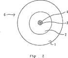
図1において、単一モード光ファイバー6は、模式的に表されており、該光ファイバー6はプレフォームをコラプスし、これからファイバーを延伸する工程の後に得られる。単一モード光ファイバー6は光伝導性コア部分4と見なすことができる。この光伝導性コア部分4は内部クラッド部分3により取り囲まれており、次に内部クラッド部分3はジャケット部分1により取り囲まれている。例えば、基体チューブはジャケット部分として適切である。前記コア部分4の屈折率は内部クラッド部分3およびジャケット部分1の屈折率より大きく、これら後者2つの部分の屈折率は略等しい。図1〜6において使用される同じ符号は互いに対応する。
【0021】
図2において、単一モード光ファイバー6の特別な態様を模式的に示す。該単一モード光ファイバー6は、光伝導性コア部分4から構成され、この光伝導性コア部分4は内部クラッド部分3により取り囲まれ、この内部クラッド部分3は緩衝層2により取り囲まれ、この緩衝層2は最後にジャケット部分1により取り囲まれる。このような単一モード光ファイバー6はジャケット部分1としてシリカ基体チューブを使用し、その後、緩衝層2、内部クラッド部分3および最後にコア部分4をそれぞれPCVD法により堆積して、本発明の方法にしたがって製造される。前記各層をシリカ基体チューブ上に堆積した後、サーマルコラプス法を実施し、その後、プレフォームを得、プレフォームからその端部において単一モード光ファイバー6を延伸する。
【0022】
図3において、単一モード光ファイバー6の特別な態様を模式的に示す。この単一モード光ファイバー6は中間層5により取り囲まれたコア部分4から構成され、この中間層5は内部クラッド部分3により取り囲まれ、この内部クラッド部分3は緩衝層2により取り囲まれ、この緩衝層2は最後にジャケット1により取り囲まれる。図3に模式的に示されたこの単一モード光ファイバー6は図2において記載したのと同じ方法で製造される。しかし、ある態様では、図3に示された緩衝層2を省略することができる。その結果、内部クラッド部分3はジャケット部分1に直接堆積され、次に内部中間層5および最後にコア部分4が堆積される。ただし、この態様は図示していない。
【0023】
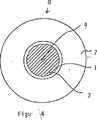
図4において、ジャケット層1は外部クラッド部分7を備える。この外部クラッド層7は図5および6においても適用される。本発明では、0.1〜8.5重量%、および好ましくは0.2〜2.0重量%の範囲でフッ素により内部クラッド部分をドーピングすることにより圧縮軸方向応力を単一モード光ファイバーのコア部分に受けさせることにおいて特に特徴がある。
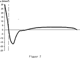
図7に、従来技術における単一モード光ファイバーの半径rの関数として応力を表すグラフを示す。このファイバーは、GeO2およびFをドープされたSiO2から形成されたコア部分およびSiO2からなる非ドープのクラッド部分から構成される。このコア部分の位置は垂直な点線で示される。したがって、コア部分がポジティブな応力下、すなわち張力下にあることが直ちにわかる。
【0024】
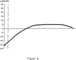
図8に、本発明の単一モード光ファイバーの半径rの関数として応力を表すグラフを示す。このファイバーはGeO2およびFをドープされたSiO2から形成されたコア部分、さらに内部クラッド部分から構成され、これは図5に応じてGeO2およびFをドープされたSiO2から形成され、他の部分は非ドープのSiO2からなる。コア部分の位置は垂直な点線により示され、コア部分は圧縮軸方向応力下にあることが直ちに明確となる。この特性は本発明に必要である。
【図面の簡単な説明】
【図1】 本発明の単一モード光ファイバーの態様を示す。
【図2】 緩衝層を備えた、本発明の単一モード光ファイバーの特別な態様を示す。
【図3】 中間層を備えた、本発明の単一モード光ファイバーの特別な態様を示す。
【図4】図1〜3にそれぞれ対応するが、これらはジャケット部分が外部クラッド部分を備えている。
【図5】図1〜3にそれぞれ対応するが、これらはジャケット部分が外部クラッド部分を備えている。
【図6】図1〜3にそれぞれ対応するが、これらはジャケット部分が外部クラッド部分を備えている。
【図7】 従来における張力対ファイバー半径のグラフを示す。
【図8】 本発明の張力対ファイバー半径のグラフを示す。[0001]
(Technical field to which the invention belongs)
The present invention comprises a photoconductive core portion, an inner cladding portion surrounding the core portion, and a jacket portion surrounding the inner cladding portion, and the refractive index of the core portion is the refractive index of the cladding portion and the jacket portion region. A method of manufacturing a single mode optical fiber that is larger and has substantially the same refractive index in the cladding and jacket regions, whereby the silica-based tube used as the jacket portion is one or more reactive gases. The inside is flushed to form the inner cladding and core, respectively, and then the substrate tube with two layers is collapsed and drawn into a single mode optical fiber. The present invention further relates to a single mode optical fiber comprising a photoconductive core portion, a cladding portion surrounding the core portion, and a jacket portion surrounding the inner cladding portion.
[0002]
(Conventional technology)
This type of optical fiber is well known and is mainly used in the field of telecommunications technology. See, for example, European Patent Publication No. 0127227, US Pat. No. 5,242,476, and US Pat. No. 5,838,866. The term “single mode” as used in the present invention is generally known to those skilled in the art and need not be further described here. Due to their low attenuation and dispersion characteristics, such optical fibers are particularly suitable for forming long distance, often thousands of kilometers, data links. Keeping the cumulative signal loss of the optical fiber to a minimum over such a significant distance is very important when attempting to transmit optical signals using a small number of intermediate amplification stations. At the commonly used transmission wavelength of 1550 nm, it has traditionally been necessary for the telecommunications industry that the total attenuation in such an optical fiber does not exceed 0.25 dB / km.
[0003]
While currently manufactured fibers may meet all such requirements for acceptable attenuation, it is nevertheless often observed that over time the attenuation increases considerably for the same optical fiber. Is done. Extensive research has shown that this phenomenon is due to the gradual hydrogen gas seeping out from the environment into the fiber, resulting in the formation of compounds such as SiH and SiOH in the fiber. These compounds show strong infrared absorption with decay peaks at wavelengths of about 1530 and 1385 nm.
[0004]
A solution for overcoming the problem of hydrogen-induced decay is disclosed in EP 477,435. According to the method disclosed herein, in order to ensure that hydrogen atoms are present at all structural defect sites of the fiber prior to the practical implementation of the fiber, the molten optical fiber is already extensively incorporated into the hydrogen-containing gas during its manufacturing process. Exposed to. However, the drawbacks of this known method only correspond to the symptoms of hydrogen induced decay, not the cause. Furthermore, this known method considerably complicates the production process and poses an additional risk of contamination of the product fiber with the hydrogen-containing gas used.
[0005]
U.S. Pat. No. 5,090,979 discloses a method of manufacturing an optical fiber that includes a pure silicon dioxide core portion, a fluorine doped silicon dioxide outer layer, a fluorine doped silicon dioxide substrate layer, and a pure It is composed of a silicon dioxide carrier layer, and the refractive index of the core portion is substantially equal to the refractive index of the carrier layer.
[0006]
U.S. Pat. No. 5,033,815 discloses a multimode optical fiber that is substantially different from the single mode optical fiber of the present invention. Furthermore, the multimode optical fiber known from this publication continues to comprise a GeO 2 -or Sb 2 O 3 -doped core part, an F-doped cladding part and an optional TiO 2 -doped jacket part, resulting in refraction of the core part The refractive index is higher than the refractive index of the cladding portion and jacket region, the refractive index of the jacket portion is substantially lower than the refractive index of the cladding portion, and the refractive index characteristics are substantially different from those of the present invention. Data relating to compressive axial stress is not disclosed in the publication.
[0007]
EP 762159 discloses a dispersion compensating fiber. It consists of a core part containing at least 10 mol% GeO 2 and a cladding part, said cladding part consisting of a first fluorine-doped cladding part, a second chlorine-doped cladding part, and a third chlorine or fluorine-doped cladding part Is done. The doping of the third cladding portion is selected such that the glass viscosity during stretching is lower than that of pure silicon dioxide glass and the temperature during stretching can be relatively low. Data on compressive axial stress is not known from this publication.
[0008]
(Problems to be solved by the invention)
Accordingly, it is an object of the present invention to provide a method for producing a single mode optical fiber in which the attenuation caused by hydrogen at a wavelength of 1550 nm is sufficiently low and reliably the total attenuation at that wavelength is at most 0.25 dB / km. That is.
As mentioned above, the object of the present invention is that the inner cladding part is composed of SiO 2 doped with fluorine in the range of 0.1 to 8.5% by weight, so that the core part is in the direction of the compression axis over the entire cross section. This is achieved by a method of manufacturing a single mode optical fiber characterized by being stressed.
[0009]
(Means for solving the problem)
The present inventor proposes that the presence of axial compression of the fiber core prevents the occurrence of the defects and, as a result, greatly reduces hydrogen induced decay. Since the present invention makes it easy to form structural defects in the silicon dioxide core due to the presence of axial tension in the fiber core, the occurrence of such defects is inherent in the presence of axial compression in the fiber core. Thus, hydrogen induced decay is substantially reduced.
[0010]
(Embodiment of the Invention)
The inventor has conducted many experiments to form a preform. It has a refractive index higher than the refractive index of the inner cladding part of the silicon oxide and the inner cladding part formed from SiO 2 containing fluorine doping on the inner surface of the substrate tube, forming the final core of the fiber A second doped layer of silicon oxide is provided. Next, the base tube formed with the core portion and the inner clad portion thus obtained is thermally collapsed to form a rod, which is finally drawn into the required fiber at one of the melt ends.
[0011]
In the present invention, the inner cladding portion is preferably doped with fluorine in the range of 0.1 to 8.5% by weight, preferably in the range of 0.2 to 2.0% by weight. Fluorine doping greater than 8.5% by weight is undesirable because it causes problems in the deposition of such layers. If the amount of fluorine is less than 0.1% by weight, no significant effect on the required compressive axial stress in the core part is produced. A maximum doping of 2.0% by weight is particularly preferred when very low attenuation losses are required. This attenuation loss is negatively affected by an increase in Rayleigh scattering. Experiments have shown that a portion of the inner cladding portion also serves as a light path for light that is transported inside the fiber core.
[0012]
Application of fluorine doping in the inner cladding reduces the refractive index of this layer. In order to adjust to a low refractive index, approximately equal to the refractive index of the region of the jacket portion, this inner cladding portion may include, for example, P 2 O 5 , TiO 2 , ZrO 2 , SnO 2 , GeO 2 , N, or Al So-called refractive index increasing doping materials such as 2 O 3 or a combination of one or more of these compounds are provided.
[0013]
In the method aspect of the present invention, it is particularly preferred to insert a buffer layer between the jacket portion and the inner cladding portion. The buffer layer has a refractive index smaller than that of the core portion and is approximately equal to the refractive index of the cladding portion and jacket portion regions.
Such a buffer layer is particularly necessary when the light quality of the jacket part is low, i.e. it means that the jacket part contains impurities. Such impurities can diffuse into the photoconductive portion of the optical fiber during continuous heat treatment for collapse to produce the preform and subsequent fiber drawing from the preform. As a result, the occurrence of attenuation is enhanced. Thus, the application of the buffer layer prevents impurities from reaching the photoconductive portion of the fiber.
[0014]
A special embodiment of the method of the present invention is preferably to insert an intermediate layer between the core portion and the inner cladding portion. This intermediate layer has a refractive index lower than the refractive index of the core portion, and is substantially equal to the refractive indexes of the regions of the inner cladding portion and the jacket portion. Single-mode optical fiber photoconductivity occurs in a layer that directly surrounds the core portion. If this layer is heavily doped, the effect of high Rayleigh scattering becomes significant. However, high doping is required to place the core portion under the required compressive axial stress. A lightly doped interlayer is preferably inserted to prevent the negative effects of excessive Rayleigh scattering that can occur.
[0015]
The inner cladding portion preferably has a thickness of 3 to 21 micrometers in the final fiber.
The required layer thickness depends on the doping of the layer. By testing, a layer thickness of less than 3 micrometers is insufficient to place the core portion under the compressive axial stress required in the present invention. The upper limit of the maximum layer thickness of the inner cladding portion is mainly determined by the processability of the preform that is ultimately drawn into the optical fiber.
[0016]
In some embodiments, further, the photoconductive core portion having one or more dopings is formed from SiO 2 having a fluorine doping in the range of 0.2 to 2 wt.%, With the one or more dopings. The core part surely has the refractive index required in the present invention, and this core refractive index is higher than the refractive index of the cladding part, and the doping is, for example, P 2 O 5 , TiO 2 , ZrO 2 , SnO 2 , It is required to include GeO 2 , N, Al 2 O 3 or a combination of one or more of these compounds.
In a special embodiment, a preform composed of a core part, an inner cladding part and a jacket part, optionally provided buffer layers and / or intermediate layers is added, for example in the form of a glass tube or a layer formed by an external CVD method A typical layer is preferably formed.
[0017]
In the present invention, the core portion and the inner clad portion, and the intermediate layer and / or buffer layer that may be provided are formed by chemical vapor deposition. In particular, it is performed by the PCVD method, preferably the plasma induction method. Since the axial length of a conventional substrate tube is many times longer than the diameter, depositing a uniform layer of material on the inner surface of such a substrate tube in a controlled manner such as sputter deposition, laser ablation deposition, etc. It is very difficult to use conventional deposition methods. In the PCVD embodiment, the chemical vapor deposition used can be successfully distributed over the entire length of the inner surface of the substrate tube. This allows a very uniform deposition on the inner wall. Further, by applying the PCVD method, it is possible to deposit a layer with a controlled doping level. This makes it possible to conveniently use this method for the deposition of the core part and the inner clad part, an intermediate layer and / or a buffer layer that may be provided in an auxiliary manner.
[0018]
The present invention further relates to a single mode optical fiber comprising a photoconductive core portion, an inner cladding portion surrounding the core portion, and a jacket portion surrounding the inner cladding portion. Here, the refractive index of the core portion is larger than the refractive indexes of the regions of the inner cladding portion and the jacket portion, and the refractive indexes of the inner cladding portion and the jacket portion region are substantially equal. Formed of SiO 2 with fluorine doping in the range of ~ 8.5% by weight, preferably in the range of 0.2-2.0% by weight, whereby the core part is subjected to compressive axial stress over its entire cross section Features.
[0019]
In a special embodiment, a single mode optical fiber has an intermediate layer inserted between the core portion and the inner cladding portion, the intermediate layer having a refractive index lower than the refractive index of the core portion, and the inner cladding portion and the jacket portion. Preferably, it is formed so as to be substantially equal to the refractive index of the region.
Further, in a special aspect of the single mode optical fiber of the present invention, it is preferable that there is a buffer layer between the jacket portion and the inner cladding portion, and this buffer layer has a refractive index lower than that of the core portion, and the inner cladding portion. And approximately equal to the refractive index of the jacket region.
Furthermore, in an embodiment, it is preferable that there is an outer cladding portion outside the jacket portion.
[0020]
(Example)
In FIG. 1, a single mode
[0021]
In FIG. 2, a special embodiment of the single mode
[0022]
In FIG. 3, a special embodiment of the single mode
[0023]
In FIG. 4, the
FIG. 7 shows a graph representing stress as a function of radius r of a single mode optical fiber in the prior art. The fiber is composed of a core part formed from SiO 2 doped with GeO 2 and F and an undoped cladding part made of SiO 2 . The position of this core portion is indicated by a vertical dotted line. Therefore, it can be readily seen that the core portion is under positive stress, i.e. under tension.
[0024]
FIG. 8 shows a graph representing stress as a function of radius r of a single mode optical fiber of the present invention. This fiber is composed of a core part formed from SiO 2 doped with GeO 2 and F, and further an inner cladding part, which is formed from SiO 2 doped with GeO 2 and F according to FIG. This portion is made of undoped SiO 2 . The position of the core part is indicated by a vertical dotted line, and it becomes immediately clear that the core part is under compressive axial stress. This property is necessary for the present invention.
[Brief description of the drawings]
FIG. 1 illustrates an embodiment of a single mode optical fiber of the present invention.
FIG. 2 shows a special embodiment of a single mode optical fiber according to the invention with a buffer layer.
FIG. 3 shows a special embodiment of a single mode optical fiber according to the invention with an intermediate layer.
FIG. 4 corresponds to FIGS. 1-3, respectively, but in which the jacket part comprises an outer cladding part.
FIG. 5 corresponds to FIGS. 1-3, respectively, but the jacket part comprises an outer cladding part.
FIG. 6 corresponds to FIGS. 1-3, respectively, but in which the jacket part comprises an outer cladding part.
FIG. 7 shows a graph of tension versus fiber radius in the prior art.
FIG. 8 shows a graph of tension versus fiber radius of the present invention.
Claims (14)
Applications Claiming Priority (3)
| Application Number | Priority Date | Filing Date | Title |
|---|---|---|---|
| NL1015405 | 2000-06-09 | ||
| NL1015405A NL1015405C2 (en) | 2000-06-09 | 2000-06-09 | Single mode optical fiber and method of manufacturing a single mode optical fiber. |
| PCT/NL2001/000433 WO2002008811A1 (en) | 2000-06-09 | 2001-06-08 | Single mode optical fibre, and method for the manufacture of a single mode optical fibre |
Publications (3)
| Publication Number | Publication Date |
|---|---|
| JP2004505000A JP2004505000A (en) | 2004-02-19 |
| JP2004505000A5 JP2004505000A5 (en) | 2005-02-03 |
| JP4808906B2 true JP4808906B2 (en) | 2011-11-02 |
Family
ID=19771518
Family Applications (1)
| Application Number | Title | Priority Date | Filing Date |
|---|---|---|---|
| JP2002514451A Expired - Fee Related JP4808906B2 (en) | 2000-06-09 | 2001-06-08 | Single-mode optical fiber and single-mode optical fiber manufacturing method |
Country Status (13)
| Country | Link |
|---|---|
| US (1) | US6754423B2 (en) |
| EP (1) | EP1287392B1 (en) |
| JP (1) | JP4808906B2 (en) |
| KR (1) | KR100789974B1 (en) |
| CN (1) | CN1227547C (en) |
| AT (1) | ATE295969T1 (en) |
| AU (1) | AU2001264412A1 (en) |
| BR (1) | BRPI0111478B1 (en) |
| DE (1) | DE60110909T2 (en) |
| DK (1) | DK1287392T3 (en) |
| NL (1) | NL1015405C2 (en) |
| RU (1) | RU2271025C2 (en) |
| WO (1) | WO2002008811A1 (en) |
Families Citing this family (14)
| Publication number | Priority date | Publication date | Assignee | Title |
|---|---|---|---|---|
| KR100322131B1 (en) * | 1999-01-28 | 2002-02-04 | 윤종용 | Optical fiber preform having OH barrier and method of fabricating the same |
| CN1261379C (en) * | 2002-01-17 | 2006-06-28 | 住友电气工业株式会社 | Method and device for manufacturing glass tube |
| US7079749B2 (en) * | 2003-01-27 | 2006-07-18 | Peter Dragic | Waveguide configuration |
| KR101166205B1 (en) * | 2003-03-21 | 2012-07-18 | 헤라에우스 테네보 게엠베하 | Synthetic silica glass tube for the production of a preform, method for producing the same in a vertical drawing process and use of said tube |
| JP2005298271A (en) * | 2004-04-12 | 2005-10-27 | Sumitomo Electric Ind Ltd | Method of manufacturing optical fiber, and opticalcal fiber |
| FR2896795B1 (en) * | 2006-01-27 | 2008-04-18 | Draka Compteq France | PROCESS FOR PRODUCING AN OPTICAL FIBER PREFORM |
| US7493009B2 (en) * | 2007-05-25 | 2009-02-17 | Baker Hughes Incorporated | Optical fiber with tin doped core-cladding interface |
| US7848604B2 (en) | 2007-08-31 | 2010-12-07 | Tensolite, Llc | Fiber-optic cable and method of manufacture |
| US8315495B2 (en) | 2009-01-30 | 2012-11-20 | Corning Incorporated | Large effective area fiber with Ge-free core |
| US7689085B1 (en) | 2009-01-30 | 2010-03-30 | Corning Incorporated | Large effective area fiber with GE-free core |
| US9052486B2 (en) | 2010-10-21 | 2015-06-09 | Carlisle Interconnect Technologies, Inc. | Fiber optic cable and method of manufacture |
| RU2457519C1 (en) * | 2010-12-03 | 2012-07-27 | Общество с ограниченной ответственностью "Фиберус" | Integral optical waveguide with activated core, double light-reflective shell and its manufacture method |
| US8929701B2 (en) | 2012-02-15 | 2015-01-06 | Draka Comteq, B.V. | Loose-tube optical-fiber cable |
| KR102029213B1 (en) * | 2017-10-30 | 2019-10-07 | 국방과학연구소 | Fabrication method of micro-fiber concave tip for radial wave propagation |
Citations (11)
| Publication number | Priority date | Publication date | Assignee | Title |
|---|---|---|---|---|
| JPS5662204A (en) * | 1979-10-25 | 1981-05-28 | Nippon Telegr & Teleph Corp <Ntt> | Optical transmission fiber and its manufacture |
| JPS56121002A (en) * | 1980-02-28 | 1981-09-22 | Nippon Telegr & Teleph Corp <Ntt> | Optical fiber for light transmission and its manufacture |
| JPS58145635A (en) * | 1982-02-15 | 1983-08-30 | エヌ・ベ−・フイリツプス・フル−イランペンフアブリケン | Manufacture of fluorine-added optical fiber |
| JPS61166503A (en) * | 1985-01-11 | 1986-07-28 | エヌ・ベー・フイリツプス・フルーイランペンフアブリケン | Fluorine-doped optical fiber and manufacture thereof |
| US4691991A (en) * | 1983-06-29 | 1987-09-08 | Ant Nachrichtentechnik Gmbh | Single mode modified W-fiber |
| JPH041706A (en) * | 1989-12-22 | 1992-01-07 | American Teleph & Telegr Co <Att> | Manufacture of optical fiber |
| US5090979A (en) * | 1989-08-02 | 1992-02-25 | Compagnie Generale D'electricite | Method of manufacturing an optical fiber preform having doped cladding |
| JPH09127354A (en) * | 1995-08-31 | 1997-05-16 | Sumitomo Electric Ind Ltd | Dispersion compensated fiber |
| JPH09221335A (en) * | 1995-12-04 | 1997-08-26 | Sumitomo Electric Ind Ltd | Production of precursor of optical fiber glass preform |
| JPH1195056A (en) * | 1997-09-17 | 1999-04-09 | Fujikura Ltd | Dispersion compensating optical fiber |
| JP2001002448A (en) * | 1999-04-26 | 2001-01-09 | Alcatel | Preform having barrier layer capable of preventing diffusion of hydrogen into optical fiber produced from the preform and production of the preform |
Family Cites Families (8)
| Publication number | Priority date | Publication date | Assignee | Title |
|---|---|---|---|---|
| US5033815A (en) * | 1979-10-25 | 1991-07-23 | Nippon Telephone & Telegraph | Optical transmission fiber and process for producing the same |
| DE4028275A1 (en) * | 1990-09-06 | 1992-03-12 | Kabelmetal Electro Gmbh | METHOD FOR THE PRODUCTION OF FIBERGLASS FIBER OPTICS WITH INCREASED STRENGTH |
| US5059229A (en) * | 1990-09-24 | 1991-10-22 | Corning Incorporated | Method for producing optical fiber in a hydrogen atmosphere to prevent attenuation |
| DE19505929C1 (en) * | 1995-02-21 | 1996-03-28 | Heraeus Quarzglas | Low attenuation optical component e.g.. fibre or preform |
| DE69630426T2 (en) * | 1995-08-31 | 2004-08-19 | Sumitomo Electric Industries, Ltd. | Dispersion-compensating fiber and process for its manufacture |
| TW371650B (en) * | 1995-12-04 | 1999-10-11 | Sumitomo Electric Industries | Method for producing an optical fiber quartz glass preform |
| JP3503427B2 (en) * | 1997-06-19 | 2004-03-08 | ソニー株式会社 | Method for manufacturing thin film transistor |
| US6131415A (en) * | 1997-06-20 | 2000-10-17 | Lucent Technologies Inc. | Method of making a fiber having low loss at 1385 nm by cladding a VAD preform with a D/d<7.5 |
-
2000
- 2000-06-09 NL NL1015405A patent/NL1015405C2/en not_active IP Right Cessation
-
2001
- 2001-06-08 AU AU2001264412A patent/AU2001264412A1/en not_active Abandoned
- 2001-06-08 AT AT01938836T patent/ATE295969T1/en not_active IP Right Cessation
- 2001-06-08 WO PCT/NL2001/000433 patent/WO2002008811A1/en active IP Right Grant
- 2001-06-08 RU RU2003100093/28A patent/RU2271025C2/en not_active IP Right Cessation
- 2001-06-08 JP JP2002514451A patent/JP4808906B2/en not_active Expired - Fee Related
- 2001-06-08 CN CNB018109144A patent/CN1227547C/en not_active Expired - Lifetime
- 2001-06-08 DE DE60110909T patent/DE60110909T2/en not_active Expired - Lifetime
- 2001-06-08 DK DK01938836T patent/DK1287392T3/en active
- 2001-06-08 KR KR1020027016696A patent/KR100789974B1/en active IP Right Grant
- 2001-06-08 EP EP01938836A patent/EP1287392B1/en not_active Expired - Lifetime
- 2001-06-08 BR BRPI0111478A patent/BRPI0111478B1/en not_active IP Right Cessation
- 2001-06-08 US US09/876,018 patent/US6754423B2/en not_active Expired - Lifetime
Patent Citations (11)
| Publication number | Priority date | Publication date | Assignee | Title |
|---|---|---|---|---|
| JPS5662204A (en) * | 1979-10-25 | 1981-05-28 | Nippon Telegr & Teleph Corp <Ntt> | Optical transmission fiber and its manufacture |
| JPS56121002A (en) * | 1980-02-28 | 1981-09-22 | Nippon Telegr & Teleph Corp <Ntt> | Optical fiber for light transmission and its manufacture |
| JPS58145635A (en) * | 1982-02-15 | 1983-08-30 | エヌ・ベ−・フイリツプス・フル−イランペンフアブリケン | Manufacture of fluorine-added optical fiber |
| US4691991A (en) * | 1983-06-29 | 1987-09-08 | Ant Nachrichtentechnik Gmbh | Single mode modified W-fiber |
| JPS61166503A (en) * | 1985-01-11 | 1986-07-28 | エヌ・ベー・フイリツプス・フルーイランペンフアブリケン | Fluorine-doped optical fiber and manufacture thereof |
| US5090979A (en) * | 1989-08-02 | 1992-02-25 | Compagnie Generale D'electricite | Method of manufacturing an optical fiber preform having doped cladding |
| JPH041706A (en) * | 1989-12-22 | 1992-01-07 | American Teleph & Telegr Co <Att> | Manufacture of optical fiber |
| JPH09127354A (en) * | 1995-08-31 | 1997-05-16 | Sumitomo Electric Ind Ltd | Dispersion compensated fiber |
| JPH09221335A (en) * | 1995-12-04 | 1997-08-26 | Sumitomo Electric Ind Ltd | Production of precursor of optical fiber glass preform |
| JPH1195056A (en) * | 1997-09-17 | 1999-04-09 | Fujikura Ltd | Dispersion compensating optical fiber |
| JP2001002448A (en) * | 1999-04-26 | 2001-01-09 | Alcatel | Preform having barrier layer capable of preventing diffusion of hydrogen into optical fiber produced from the preform and production of the preform |
Also Published As
| Publication number | Publication date |
|---|---|
| EP1287392A1 (en) | 2003-03-05 |
| BR0111478A (en) | 2003-07-01 |
| KR100789974B1 (en) | 2007-12-31 |
| RU2271025C2 (en) | 2006-02-27 |
| US20020015570A1 (en) | 2002-02-07 |
| KR20030007913A (en) | 2003-01-23 |
| NL1015405C2 (en) | 2001-12-12 |
| JP2004505000A (en) | 2004-02-19 |
| DE60110909T2 (en) | 2006-01-19 |
| DE60110909D1 (en) | 2005-06-23 |
| DK1287392T3 (en) | 2005-08-15 |
| WO2002008811A1 (en) | 2002-01-31 |
| EP1287392B1 (en) | 2005-05-18 |
| CN1436310A (en) | 2003-08-13 |
| CN1227547C (en) | 2005-11-16 |
| AU2001264412A1 (en) | 2002-02-05 |
| US6754423B2 (en) | 2004-06-22 |
| BRPI0111478B1 (en) | 2015-09-15 |
| ATE295969T1 (en) | 2005-06-15 |
Similar Documents
| Publication | Publication Date | Title |
|---|---|---|
| US7089765B2 (en) | Method of making a jacketed preform for optical fibers using OVD | |
| US8265439B2 (en) | Optical fiber preform | |
| CN102798927B (en) | Single-mode fiber and manufacture method thereof | |
| CA2565879C (en) | Long wavelength, pure silica core single mode fiber and method of forming the same | |
| JP4808906B2 (en) | Single-mode optical fiber and single-mode optical fiber manufacturing method | |
| JP2007536580A5 (en) | ||
| CN105911639B (en) | A kind of low decaying single mode optical fiber | |
| CA2207506C (en) | Dispersion compensating fiber and its manufacturing method | |
| JPS6113203A (en) | Single mode optical fiber | |
| US20080050076A1 (en) | Low loss photonic waveguide having high index contrast glass layers | |
| CN104216044B (en) | A kind of low attenuation bend-insensitive single-mode optical fiber | |
| KR100688631B1 (en) | Substrate tube and process for producing a preform for an optical fiber | |
| US6530244B1 (en) | Optical fiber preform having OH barrier and fabrication method thereof | |
| US6603914B2 (en) | Dispersion compensating fiber with reduced splice loss and methods for making same | |
| US6988379B2 (en) | Method of manufacturing large capacity preforms by MCVD | |
| JP2004067459A (en) | Optical fiber preform, its manufacturing method, and optical fiber obtained by drawing the preform | |
| US7008696B2 (en) | Optical fiber preform having barrier layers for hydroxyl (OH) radicals | |
| US20020000104A1 (en) | Methods of making preform and optical fiber | |
| WO2001072648A1 (en) | Substrate tube and process for producing a preform for an optical fiber | |
| US7849713B2 (en) | Optical fibre having low splice loss and method for making it | |
| JPH0612364B2 (en) | Polarization-maintaining optical fiber base material | |
| KR20050084469A (en) | Optical fibre having low splice loss and method for making it |
Legal Events
| Date | Code | Title | Description |
|---|---|---|---|
| A521 | Request for written amendment filed |
Free format text: JAPANESE INTERMEDIATE CODE: A523 Effective date: 20040421 |
|
| A521 | Request for written amendment filed |
Free format text: JAPANESE INTERMEDIATE CODE: A523 Effective date: 20040514 |
|
| A621 | Written request for application examination |
Free format text: JAPANESE INTERMEDIATE CODE: A621 Effective date: 20080411 |
|
| RD03 | Notification of appointment of power of attorney |
Free format text: JAPANESE INTERMEDIATE CODE: A7423 Effective date: 20080411 |
|
| A131 | Notification of reasons for refusal |
Free format text: JAPANESE INTERMEDIATE CODE: A131 Effective date: 20110405 |
|
| A521 | Request for written amendment filed |
Free format text: JAPANESE INTERMEDIATE CODE: A523 Effective date: 20110620 |
|
| TRDD | Decision of grant or rejection written | ||
| A01 | Written decision to grant a patent or to grant a registration (utility model) |
Free format text: JAPANESE INTERMEDIATE CODE: A01 Effective date: 20110726 |
|
| A01 | Written decision to grant a patent or to grant a registration (utility model) |
Free format text: JAPANESE INTERMEDIATE CODE: A01 |
|
| A61 | First payment of annual fees (during grant procedure) |
Free format text: JAPANESE INTERMEDIATE CODE: A61 Effective date: 20110818 |
|
| FPAY | Renewal fee payment (event date is renewal date of database) |
Free format text: PAYMENT UNTIL: 20140826 Year of fee payment: 3 |
|
| R150 | Certificate of patent or registration of utility model |
Ref document number: 4808906 Country of ref document: JP Free format text: JAPANESE INTERMEDIATE CODE: R150 Free format text: JAPANESE INTERMEDIATE CODE: R150 |
|
| R250 | Receipt of annual fees |
Free format text: JAPANESE INTERMEDIATE CODE: R250 |
|
| R250 | Receipt of annual fees |
Free format text: JAPANESE INTERMEDIATE CODE: R250 |
|
| R250 | Receipt of annual fees |
Free format text: JAPANESE INTERMEDIATE CODE: R250 |
|
| R250 | Receipt of annual fees |
Free format text: JAPANESE INTERMEDIATE CODE: R250 |
|
| R250 | Receipt of annual fees |
Free format text: JAPANESE INTERMEDIATE CODE: R250 |
|
| R250 | Receipt of annual fees |
Free format text: JAPANESE INTERMEDIATE CODE: R250 |
|
| LAPS | Cancellation because of no payment of annual fees |