CN1218376A - Garment set hanger with adjustable support bar - Google Patents
Garment set hanger with adjustable support bar Download PDFInfo
- Publication number
- CN1218376A CN1218376A CN97194473A CN97194473A CN1218376A CN 1218376 A CN1218376 A CN 1218376A CN 97194473 A CN97194473 A CN 97194473A CN 97194473 A CN97194473 A CN 97194473A CN 1218376 A CN1218376 A CN 1218376A
- Authority
- CN
- China
- Prior art keywords
- hanger
- piece clothes
- fixture
- mid portion
- sidepiece
- Prior art date
- Legal status (The legal status is an assumption and is not a legal conclusion. Google has not performed a legal analysis and makes no representation as to the accuracy of the status listed.)
- Pending
Links
Images


Classifications
-
- A—HUMAN NECESSITIES
- A47—FURNITURE; DOMESTIC ARTICLES OR APPLIANCES; COFFEE MILLS; SPICE MILLS; SUCTION CLEANERS IN GENERAL
- A47G—HOUSEHOLD OR TABLE EQUIPMENT
- A47G25/00—Household implements used in connection with wearing apparel; Dress, hat or umbrella holders
- A47G25/14—Clothing hangers, e.g. suit hangers
- A47G25/48—Hangers with clamps or the like, e.g. for trousers or skirts
- A47G25/483—Hangers with clamps or the like, e.g. for trousers or skirts with pivoting clamps or clips having axis of rotation parallel with the hanger arms
- A47G25/485—Hangers with clamps or the like, e.g. for trousers or skirts with pivoting clamps or clips having axis of rotation parallel with the hanger arms with a plurality of clips integral with, or supported by, the trouser-supporting bar
-
- A—HUMAN NECESSITIES
- A47—FURNITURE; DOMESTIC ARTICLES OR APPLIANCES; COFFEE MILLS; SPICE MILLS; SUCTION CLEANERS IN GENERAL
- A47G—HOUSEHOLD OR TABLE EQUIPMENT
- A47G25/00—Household implements used in connection with wearing apparel; Dress, hat or umbrella holders
- A47G25/14—Clothing hangers, e.g. suit hangers
- A47G25/44—Slidable hangers ; Adjustable hangers
- A47G25/441—Slidable hangers ; Adjustable hangers having adjustable width
-
- A—HUMAN NECESSITIES
- A47—FURNITURE; DOMESTIC ARTICLES OR APPLIANCES; COFFEE MILLS; SPICE MILLS; SUCTION CLEANERS IN GENERAL
- A47G—HOUSEHOLD OR TABLE EQUIPMENT
- A47G25/00—Household implements used in connection with wearing apparel; Dress, hat or umbrella holders
- A47G25/14—Clothing hangers, e.g. suit hangers
- A47G25/16—Clothing hangers, e.g. suit hangers for complete outfits
-
- A—HUMAN NECESSITIES
- A47—FURNITURE; DOMESTIC ARTICLES OR APPLIANCES; COFFEE MILLS; SPICE MILLS; SUCTION CLEANERS IN GENERAL
- A47G—HOUSEHOLD OR TABLE EQUIPMENT
- A47G25/00—Household implements used in connection with wearing apparel; Dress, hat or umbrella holders
- A47G25/14—Clothing hangers, e.g. suit hangers
- A47G25/28—Hangers characterised by their shape
Landscapes
- Holders For Apparel And Elements Relating To Apparel (AREA)
Abstract
A hanger particularly suited for use with garment sets such as a coat and trouser garment set or a coat and skirt garment set. The hanger includes an upper attachment member which is preferably hook shaped for attachment with a closet rod or the like and a main hanger body which is joined with the attachment member and includes an intermediate section and two shoulder sections extending outwardly to opposite sides of the intermediate section so as to support the garment piece that includes shoulders. The invention further includes a pivoting garment holder for the other garment piece in the set. The pivoting garment holder is supported at an upper end by the intermediate section either by an interface section provided at an upper portion of the intermediate section or by a cavity formed in a mid region of the intermediate section.
Description
Invention field
The present invention relates to a kind of garment set hanger that is used for the such suit of garment set, for example overcoat/trousers or overcoat/skirt, particularly relate to a kind of garment set hanger with adjustable support bar or fixture.
Background of invention
Traditional general feature of clothes hanger is to comprise a hook-like part, and this hook-like part is connected with the shoulder support of hanger.Hook-like part is usually designed to a closet cramp bar or analog and is connected.The shoulder support is designed for supporting a suit jacket etc., and it comprises two shoulder supporting brackets that outwards stretch and have level and smooth profile like this.What stretch between the free end of these supports is a horizontal supports, and this horizontal supports is designed to support trousers or a skirt.
Such clothes hanger has disadvantage, because jacket or overcoat hang with the horizon bar of trousers above having hidden.Like this, in order to take trousers away, must at first remove jacket or overcoat from bar.Equally, jacket or overcoat could be put back on the hanger after getting back on the bar up to trousers are relay, otherwise before trousers are in place, must remove jacket or overcoat.This structure is obviously unfavorable, because a people wore trousers, reversed in order when undressing usually earlier before wearing jacket or overcoat.
The United States Patent (USP) 5038979 of Traylor relates to and the relevant same problem of above-mentioned conventional garments hanger.In order to make great efforts to address this problem, the specification of Traylor has been described a compound clothes hanger, this compound clothes hanger comprises and has the collar and the pair of brackets of takeing on support below one, this support be rigidly fixed on the collar and from the outside horizontal stretching of the collar so that support a cramp bar between its free end.Although this design has solved the problems referred to above that traditional clothes hanger brings, but it has caused a new problem, for example require bigger space, in very valuable family and the retail location of many closets or storage rack space, this is the problem of an especially severe.Another problem is that the design of Traylor lost the advantage of conventional hanger, the advantage of conventional hanger is to make overcoat and trousers CONTACT WITH FRICTION (on identical hanger and/or adjacent hanger), this helps avoid trousers slippage in many cases, and by make trousers with respect to the adjacent clothes that is supported with contact easily suitably the location, thereby help avoid gauffer.
Summary of the invention
The present invention is designed to solve the related foregoing problems of general conventional hanger, avoids bringing new problem, excessive usage space for example simultaneously.For realizing this point, the present invention relates to a kind of hanger that comprises a connector and a hanger main body.The hanger main body comprises a mid portion and outwards stretches in opposite direction to support first and second shoulder supports with single-piece clothes of shoulder from this mid portion.Connector is connected with mid portion.Hanger also comprises a single-piece clothes fixture that is used for supporting another single-piece clothes.This single-piece clothes fixture is by body abutment, and single-piece clothes fixture comprises rotatable parts, and these rotatable parts are arranged between a primary importance and the second place, in this primary importance, rotatable parts are near the shoulder support, and in this second place, rotatable parts are removed from the shoulder support.
The rotatable parts of hanger of the present invention are supported by mid portion, and mid portion comprises an interface portion that is connected with jockey.Single-piece clothes fixture preferably includes a pivoting lever device, and this pivoting lever device is by mid portion supporting and be stretched over the relative both sides of mid portion, and the pivoting lever device is arranged vertically between shoulder support and connector.
In one embodiment, the pivoting lever device of hanger comprises two bar portions that fixedly secure on interface portion, and single-piece clothes fixture also comprises two sidepieces, and this sidepiece stretches along the direction of leaving pivoting lever portion two ends.The upper end of sidepiece is connected with pivoting lever portion rotationally.Single-piece clothes fixture also comprises a horizontal supporting portion by the following end bearing of two sidepieces.Sidepiece can be made by wire, and each upper end of sidepiece comprises a coiler part that twines around pivoting lever portion.
In a preferred embodiment, first sidepiece has a coils loop bottom, and second sidepiece has crooked receiving portion.Horizontal supporting portion comprises a horizon bar and a contacting metal silk part, and contacting metal silk part forms whole with coils loop bottom and crooked receiving portion and stretches betwixt.Horizon bar has one first end and one second end, and this first end is firmly admitted by the coils loop bottom, and this second end is fit to be contained in the crooked receiving portion.
The best lateral arrangement of sidepiece is in free end inside, the bottom of shoulder, therefore each sidepiece comprise at least one can with a part that front surface contacts of shoulder, and, trousers take away or when initially hanging the implantation site, this part can be followed and rotate and leave front surface forward when being positioned at.
The bottom of sidepiece also is arranged to be contacted with a front surface of shoulder by the end of the horizontal supporting portion of sidepiece supporting, and the bottom of this sidepiece can be followed and is rotated away from this front surface forward.
In one embodiment of the invention, connector comprises a hook portion and a spherical bottom, and this sphere bottom firmly is contained in a cavity that is arranged in the hanger main body.
A preferable configuration of the present invention is characterised in that a mid portion comprises an interface portion that combines with connector and a neck, this neck is arranged vertically between interface portion and shoulder support, and single-piece clothes fixture has the top that combines with interface portion, a middle part and the following horizontal supporting of of combining with this middle part portion, makes that horizontal supporting portion is arranged under this neck down.
In the present invention, the top of single-piece clothes fixture comprises a pivoting lever, and this pivoting lever is connected with interface portion is whole, and perhaps this pivoting lever is connected rotationally with interface portion.And connector can combine with mid portion (for example monoblock plastic body) integral body or be fixed thereon.
In another embodiment of the present invention, mid portion comprises an interface portion, and this interface portion has at least one receiving orifice of admitting single-piece clothes fixture rotationally.Receiving orifice is a through hole in one embodiment, and this through hole runs through interface portion, and the upper support bar of single-piece clothes fixture runs through this through hole.For this structure, single-piece clothes fixture is the annular element of a closure preferably, and this closed annular spare has each end that leaves the upper support bar and two sidepieces that stretch.Closed annular spare also comprises a lower horizontal cramp bar that is connected with the lower end of sidepiece.One embodiment of the present of invention comprise a hanger, and this hanger has upper support bar side direction is locked in the device to avoid the upper support bar to be displaced sideways in the through hole.
In one embodiment, hanger of the present invention is characterised in that and also comprises a position rotation lock device that this position rotation lock device is used for releasably locking single-piece clothes fixture in the second place and/or primary importance.
In another embodiment of the present invention, single-piece clothes fixture comprises by a left insertion section and the top that make right insertion section, each should insertion section, a left side and right insertion section have a free end by the interface portion rotatable support.Insertion section, the left and right sides preferably includes a device, in order to insertion section, left and right sides side direction is locked in the receiving orifice that is positioned at interface portion.
Like this, in one embodiment of the invention, single-piece clothes fixture has a top being rotatably connected with mid portion, stretches downwards and two sidepieces between the free end of shoulder and a lower support portion that is connected with a lower end of sidepiece from top.Lower support portion comprises a basic horizontal part, and another single-piece clothes is bearing on this horizontal component.Lower support portion comprises a horizon bar and two clips that lateral spacing is opened that are bearing on this horizon bar.
Hanger feature of the present invention also is to comprise a single-piece clothes fixture, this single-piece clothes fixture has the center-pole of a vertical stretching, the upper end of this center-pole rotatably is contained in the interior formed groove of mid portion, parts of the following end bearing of this center-pole, these parts are used for supporting another single-piece clothes.
In other words, the present invention relates to a kind of hanger, this hanger has a hanger main body, and this main body comprises a mid portion that combines with connector, this main body also comprise from the centre part outwards stretch in opposite direction with supporting have shoulder a single-piece clothes first and second the shoulder supports.Hanger also comprises a single-piece clothes fixture that is used for fixing another single-piece clothes, a mid portion that this single-piece clothes fixture has a top being rotatably connected with mid portion, stretch downwards from the top of single-piece clothes fixture and a bottom with the device that is used for contacting and support another single-piece clothes.
Mid portion comprises an interface portion, and single-piece clothes fixture can comprise a pivoting lever that is fixed on this interface portion and the mid portion that comprises two sidepieces.Sidepiece and bottom are made by the wire of continuous length, and this wire has by the turnable coiled upper end of admitting of pivoting lever.
Perhaps, top comprises the bar of a continuous basic horizontal, and this horizon bar runs through a through hole that is positioned at interface portion.As another embodiment, the top of hanger comprises a top part, this top part is contained in the cavity that forms in the mid portion rotationally, and this mid portion can comprise an arch bar of arranging placed in the middle, and this arch bar is stretched over a horizontal fixed part downwards from top.
The invention still further relates to a kind of method of making hanger, the step of this method comprises hanger main body of formation, and this hanger main body comprises a mid portion and outwards stretches to support two shoulder portions of the first single-piece clothes from this mid portion.This method also comprises single-piece clothes fixture that is used for supporting another single-piece clothes of formation.This single-piece clothes fixture comprises a top, at least one mid portion and a bottom by the main body rotatable support of hanger, and this bottom provides the device that is used for contacting and supporting another single-piece clothes.The preferred embodiment summary
With reference to the accompanying drawings, will make advantage of the present invention clearer by following description, wherein:
Fig. 1 represents the front view of a preferred embodiment of the present invention;
Fig. 2 represents the side view of embodiment shown in Figure 1;
Fig. 3 represents a viewgraph of cross-section of the transversal III-III intercepting along Fig. 1;
Fig. 4 represents to be used for to support the front view of the embodiment as shown in Figure 1 of a cover suit clothes;
Fig. 5 represents the side view of state shown in Figure 4;
Fig. 6 represents to be supported with the view that turning to of two-piece-dress clothes taken away or initially extension the hanger supporting member of pattern;
Fig. 7 represent as shown in Figure 6, difference is a removed view in the two-piece-dress clothes;
Fig. 8 represents the front view of second preferred embodiment of the present invention;
Fig. 8 A represents the cutaway view with similar another embodiment of the present invention shown in Figure 8;
Fig. 9 is the viewgraph of cross-section of the transversal IX-IX intercepting along Fig. 8;
Fig. 9 A represents along the viewgraph of cross-section of the transversal IX A-IX A intercepting of Fig. 8 A;
Figure 10 represents that one of the present invention is improved embodiment and the similar viewgraph of cross-section of Fig. 9;
Figure 11 represents the bottom, cross-sectional view of another preferred embodiment of the present invention;
Figure 12 represents the bottom, cross-sectional view of another preferred embodiment of the present invention;
Figure 13 is illustrated in the viewgraph of cross-section of the another embodiment of the present invention in the viewgraph of cross-section zone of Figure 10; With
Figure 14 represents the positive view of another embodiment of the present invention.DESCRIPTION OF THE PREFERRED
Structure and the operation of first embodiment of Fig. 1-7 expression garment set hanger 20 of the present invention.
As shown in the figure, hanger 20 comprises upper connector 22, the first single-piece clothes rotational fixture devices 24 and the second single-piece clothes supporting part 26.
Now, with reference to figure 1 and 3, upper connector 22 is made by a hook-type metalwork with crooked free end 28 and spherical base 30 (Fig. 3).Spherical base 30 is contained in the cavity 32 in the chimeric interface portion 34 of hanger 20.Cavity 32 comprises expansible and contains a cylindrical openings 36 of spherical portion 38.
Like this, the spherical base 30 of upper connector 22 can adopt or not adopt additional fixation device for example adhesive or key/groove structure can insert fast in the cavity 32 so that hold wherein.And as shown in Figure 3, when chimeric interface portion 34 was made by a kind of plastic material, during molding process, the bottom 30 of upper connector 32 obtained covering.Many one of them of example of may changing that upper connector 22 shown in Figure 1 is that the present invention intends covering.For example, do not adopt a metal upper connector shown in Figure 1, but adopt a kind of plastics hook-type connector, this plastics hook-type connector forms whole with the chimeric interface portion of being made by identical plastic material 34 simultaneously.Perhaps, when upper connector was independent of chimeric interface portion 34 and makes, the cylindrical cavity of thread structure or band adhesive was also very reliable.And, do not adopt hook shaped component, but adopt the connector of other shape, for example ground such as accommodation often can see have on straight parts of ball point, this also is reliable.
The first single-piece clothes rotational fixture device 24 is characterised in that pivoting lever device 40, and this pivoting lever device 40 comprises first pivoting lever part 42 of stretching to chimeric interface portion 34 1 sides and the second pivoting lever part 44 of stretching to chimeric interface portion 34 opposite sides.Two pivoting lever parts 42,44 have a common central shaft and are positioned on the horizontal plane.And, first and second pivoting levers 42,44 free end 46 and free end 48 preferably outwards are stretched over a zone, and this zone is the zone between the corresponding outer end 50,52 of five equilibrium vertical plane being arranged in that Fig. 1 transversal III-III intercepted and the second single-piece shoulder support 96 and 98.For example, in a preferred embodiment, free end 46 and 48 drops on from perpendicular bisected towards each outer end in overhanging 25% to 75% the intermediate range.Best, this scope is at 35-55%.
The first fixture device 24 also comprises rotation extension 54, in this specific embodiment, rotating extension 54 is wireworks, this wirework be characterised in that first coil twine end 56, first sidepiece 58, coil be fastened part 60, clothes contact 62, accept bend 64, second sidepiece 66 and second coil and twine end 68.
Although as described below, the present invention includes other and can select feature, for example bar 40 grades do not fixedly secure on neck 82 but itself is rotatable, and pivoting lever part 40 preferably forms whole with the central neck portion 82 of the second single-piece clothes part 26.The second single-piece clothes part 26, connector 22 and pivoting lever device 40 can be molded as an integral plastics main body, and this mechanography does not need the special-purpose demoulding of hydraulic pressure (hydraulic special release dies) just can finish the demoulding of mechanograph.
In the embodiment shown in fig. 1, the coil part 60 that is fastened maintains fixed bar 84 with the fixed form that can rub.Fixed bar 84 has free end 86 and 88.Arrange in the scope of the free end 88 aforementioned perpendicular bisected face that transversal III-III is intercepted in deviating from Fig. 1, this scope is the 75-100% from the total length of the outer end 52 of this five equilibrium face to the second single-piece clothes supporting part 26, be preferably 85-95%, and be preferably 90%.Opposed free ends extends to the opposite side of five equilibrium face on a 50-50 basis.
As shown in Figure 1, fixed bar 84 is horizontally disposed with by rotating extension 54, and the length of fixed bar 84 can be arranged under the second single-piece clothes supporting part 26 it, wire part 74 and coil be fastened between the part 60 the position, composition surface by inwardly a small amount of crooked (inside sweep is represented by the label among Fig. 1 90) with convenient above-mentioned layout.A kind of part 92 that similarly curves inwardly (the actual part 92 that curves inwardly can represent to accept the initial part of bend 64) is set in vertical wire part 80 and the position, composition surface of accepting bend 64.Like this, the length of fixed bar 84 and the vertical component 58 of rotation extension 54 and 80 position and length compress setting with respect to the second single-piece clothes supporting part 26.Perhaps, fixed bar 84 is arranged in the front of the second single-piece clothes supporting part 26, and below neck 82 to the optional position between the following bottom 3-6 inch of the second single-piece clothes supporting part 26.And free end 86 can outwards stretch with 88 so that contact with the second single-piece clothes supporting part 26, rather than the part 74 of rotating extension 54 is contacted with 98 with shoulder support 96 with 80.
The second single-piece clothes, for example overcoat or jacket are supported by the second single-piece clothes supporting part 26 of hanger 20.The second single-piece clothes supporting part 26 comprises aforementioned neck 82, and the main body 94 of this neck 82 and the second single-piece clothes supporting part 26 forms an integral body.Main body 94 is preferably made by plastic material, and in the present embodiment, main body 94 is molded as integral body with neck 82 and pivoting lever 40.Perhaps, a kind of wooden hanger can be made by different adhering components together.Main body 94 comprises the first shoulder support 96 and the second shoulder support 98.The first and second shoulder supports 96,98 stretch downwards and forward from middle part 100.Like this, the mid portion of the second single-piece clothes supporting part comprises interface portion 34, neck 82 and mid portion 100. Support 96,98 stretches forward or bending is convenient at this support and rotates to produce between the extension 54 compress action.The feature of main body 94 also is to have the upper surface 102 of a smooth curved and the bottom surface recess 104 of an economical with materials.
Below with reference to Fig. 1-7, particularly Fig. 4-7, the operation of said apparatus is described.As shown in Figure 4, overcoat or jacket 106 are bearing on the shoulder support 96 and 98 of the second single-piece clothes supporting part 26.Be furnished with the first single-piece clothes 110 before the front surface 108 of overcoat or jacket 106, the first single-piece clothes of this shown in the figure is trousers.Trousers 110 are bearing on the cramp bar 84 that basic horizontal arranges and clamp in place by clothes contact 62.
In position shown in Figure 4, the first single-piece clothes fixture device 24 is in one and carries fully so that prepare to put into the interior position of closet.In this position of preparing suspension, trousers or trousers 110 contact with the front surface 108 of overcoat 106.Equally, free end 86 with 88 and/or vertical component 74 also contact with 80 with the front surface 108 of overcoat 106.Deposit at this cloth, trousers are smooth layout, and the front surface 108 of overcoat 106 also is presented on the state that its front surface kept when wearing overcoat.Therefore, reduced the trousers gauffer, particularly because the problem of the distortion of overcoat front surface 108 or the folding front surface gauffer that causes.
Fig. 5 is the side view of device shown in Figure 4, has wherein represented the extension forward and the bending of the first shoulder support 96 and the second shoulder support 98.Fig. 5 has also represented the side view and the position P1 for preparing to hang of the profile of wire part 70,72 and 74.
Fig. 6 represents to take away from hanger 20 initial step (perhaps, just trousers 110 are placed to contact with the front surface 108 of overcoat 106 so that can make a whole set of clothes be suspended on stage in closet etc.) of trousers 110.The position of preparing suspension and preparing to take away is represented by " P1 " and " P2 " in Fig. 6.Like this, the P2 among Fig. 6 represents that the position of preparing to take away, P1 are represented by dotted lines fixture device 24 and present and make trousers 110 and overcoat 106 reach position contacting.
As shown in figs. 1 and 6, rotate coil winding end 56 windings two or three circles of extension 54.Outmost turns directly puts in wire part 70.The optimized angle that Fig. 6 also represents to keep between position P1 and the P2 at interval.This angle θ is enough to provide the space of necessity between the front surface 108 of overcoat 106 and trousers 110, therefore, trousers 110 can be taken away or hang on the fixed bar 84 from fixed bar 84 with aforementioned manner, meanwhile do not clash with overcoat 106.
Best, twine the friction that exists between the end 56 to a certain degree in pivoting lever part 42 and coil, so the required interval θ of interim at least maintenance between P1 and P2.Yet,, rely on the another hand can carry out necessary adjusting reliably so that fixed bar 84 navigates to required interval angle can also insert, dismantle (when using clip) simultaneously or take trousers or skirt away because a hand catches neck 82 or connector 22.In an optional embodiment who does not represent, first and second winding arounds 56 and 68 can be contained in respectively in the groove than minor diameter that is slightly inwardly formed by free end 46,48 in bar portion 42 and 44, therefore, guaranteed further that coil 56 and 68 does not change the position or from an end slippage of pivoting lever device 40.In this optional embodiment, coil 56 and 68 floats in described groove, and in it and outer surface near or contact with sidewall for the groove lining in the pivoting lever device 40.And, be fixed on bar portion 42 and 44 by free end and can obtain the bias voltage closing device coil 56 and 58.After hanging up trousers, this makes tumbler 54 auto-closings.
Fig. 7 represents to have taken away and fixed bar 84 rearranges position same as shown in Figure 1 (promptly prepare hang position P1) view same as shown in Figure 6 except trousers 110.As shown in Figure 7, wire profile and after the interval between position P1 and the P2 makes to take trousers away is easy to take away overcoat.
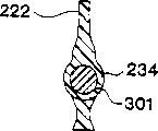
The hanger 200 of Fig. 8 and 9 expressions, second preferred embodiment of the present invention.Hanger 200 shown in Fig. 8 and 9 comprises first parts 202 and second parts 204, and each parts is preferably made by a kind of plastic material.Best, second parts 204 are molded on preformed first parts 202.Because this top molded (overmo1ding arrangement) structure, preferably different parts use different plastic materials, and the plastic material of parts 202 is than the fusion temperature height of the plastic material of parts 204.And, can use different materials, for example parts 204 are used plastic material, and parts 202 are used metal material.
Hanger 200 has the jockey 222 of Unitarily molded formation, and this jockey 222 puts in chimeric interface portion 234.Chimeric interface portion 234 is stretched over neck 282 downwards, and neck 282 extends to mid portion 300 successively.Be provided with the first shoulder support 296 and the second shoulder support 298 in the relative both sides of mid portion 300.Jockey 222, mid portion 300 and shoulder support 296 conform to the profile of corresponding component in 298 shape the foregoing description best and shown in Figure 1.
As shown in Figure 9, chimeric interface portion 234 comprises cylindricality through hole 301, and this through hole 301 stretches (see figure 8) and forms the arm 307 of interface portion 234 and 309 free open end between end 303 and 305.Interface portion 234 is held the pivoting lever 240 of parts 202 slidably, passes through hole 301 stretching, extensions continuously thereby these parts 202 are integral single piece.By being slidably engaged between parts 202 and interface portion 234, therefore, parts 202 can be turned to and position P1 shown in Figure 6 and the similar position of P2.Like this, as shown in Figure 8, rotate extension 254 with the bar 240 whole sidepieces 258 that are connected and 266 with embodiment illustrated in fig. 1 in sidepiece 58 and 66 similar modes stretch.
Be provided with in the lower end of sidepiece 258 and 266 level towards cramp bar 284, the end of cramp bar 284 and sidepiece 258 are connected with 266 bottom is whole.Although do not express, each the foregoing description and following embodiment comprise vertical plane shoulder support 296 and 298, rather than the support that stretches forward for example shown in Figure 2.And jockey 222 can be the separate part that is fixed to interface portion 234 upper ends.
Do not adopt the top molding technique (overmo1dingtechnique) of above-mentioned Fig. 8 embodiment, but adopt a similar pivoting lever 240 continuously with the two part structures of Fast Installation for parts 204.That is, parts 204 are made with second hollow half shell identical with the first hollow half hull shape shape by one first molded hollow half shell.Along with first parts 202 are arranged in the slit that is positioned at each half shell, each half shell of component parts 204 links together along its edge.This structure can be saved plastic material basically, has increased additional fastening step (for example, plastics clip and/or the adhesive on the connection edge of shell) in the manufacturing process but make.In this embodiment, parts 222 can be made into the separate part of an identical or different material, and on two and half shells that are fixed together fix in position.
Figure 13 is that it has represented another possible feature of the present invention along the viewgraph of cross-section of the transversal X III among Fig. 8-X III intercepting.As shown in figure 13, pivoting lever 240 has radially relative protuberance 311, and protuberance 311 is contained in the cannelure 313 on the inner surface that is formed at wall surface 301.Protuberance 311 provides a kind of lock function and has had rotating function, and this lock function has prevented that pivoting lever 240 is with respect to through hole 301 lateral slidings.On relative arm 307, also be provided with a kind of similar lateral sliding locking device.And a kind of relative device is provided, wherein key 311 inwardly stretches from surface 301, and forms a cannelure in pivoting lever 240.
For structure shown in Figure 8, parts 202 turn to a trousers/skirt and take (or initial extension) pattern away from a clothes memory location, and vice versa.In order to help to make parts 202 location, desirable position P1 and P2 can provide a kind of structure for example shown in Figure 10.Structure shown in Figure 10 represents to have the pivoting lever 240 of the spherical protuberances 315 that radially outward stretches away from pivoting lever 240.Slit 317 with block cavity 319 and 321 is provided in the wall surface of through hole 301, and this block cavity is positioned at the opposite end of slit 317. Cavity 319 and 321 radially outward extends to the degree of depth that exceeds slit 317 slightly, so spherical protuberances 315 slightly deformed when mobile in slit 317, moves to one of them and snapped into place of cavity 319 and 321 then.
Fig. 8 A and 9A represent another preferred embodiment of the present invention.Near in Fig. 8 chimeric interface portion 234 and pivoting lever 240 the zone, the embodiment shown in Fig. 8 A is designed to same as shown in Figure 8 basically.Shown in Fig. 8 A, pivoting lever 240 ' is characterised in that and comprises that first insertion end 323 and second insertion end 325, this first insertion end 323 and second insertion end 325 are the sliding friction structure and are contained in receiving orifice 327 and 329.And, in a single day when inserting in receiving orifice 327 and 329, be displaced sideways for fear of end 323 and 325, a low clearance circular protrusion 331 and a corresponding annular recess 333 are provided.Circular protrusion 331 and annular recess 333 form on insertion end 323 and 325, therefore, can Fast Installation enter in one of them of receiving orifice 327 and 329 correspondences.
Do not have Fast Installation circular protrusion 331 and 333 and can form the embodiment shown in Fig. 8 A and the 9A yet, make free end 335 and 337 reply the inherent trend that forms opposite joining relation because in pivoting lever 240 ', have.
The advantage of embodiment shown in Fig. 8 A and the 9A is that each parts can use the material of any kind that comprises common plastic material reliably, links together because each parts can independently form then.
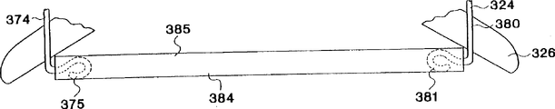
Figure 11 and 12 represents two other embodiment of the present invention with cut-away.The hanger of Figure 11 has and above-mentioned one second similar single-piece clothes fixture part 326.And except replacing cramp bar 84, coil 60, contacting metal silk part 62 and groove 64, the first fixture part 324 has with the fixture device 24 of Fig. 1 similarly constructs, and vertical component 375 and 380 lower end are respectively equipped with an annular end 375 and 381. Annular end 375 and 381 is inserted the openend of tubular piece 384, and tubular piece 384 is a cardboard pipe preferably, and cardboard pipe as shown in figure 11 is provided with the outer surface 385 of a viscose glue.Like this, tubular piece 384 is the trousers fixed bar of Figure 11 embodiment.
The first fixture part 324 also has for example structure shown in Fig. 8 and 8A.For example, do not adopt the wire main body, the first fixture part 324 of Figure 11 can be an independent plastic mould (among similar Fig. 8), this independent plastic mould has the isolated end of two annulars as shown in figure 11, or two plastic side parts that separate, these plastic side parts have a kind of upper end structure and two annular end shown in Figure 11 shown in similar Fig. 8 A.And, can adopt two independent wires structures, this wire structure has annular end shown in Figure 11 and corresponding spherical upper end, and this sphere upper end is contained in the arm 307 that is arranged in the corresponding interface spare and 309 one receives cavity.Spherical upper end and reception cavity can adopt similar structure shown in Figure 3, so that jockey 22 is connected with interface portion 34.This spheric end/accept cavity to allow to rotate keeps the suitable lateral register of parts of each hanger simultaneously.
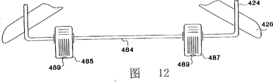
Figure 12 represents to have another embodiment in order to the horizontal supporting bar 484 of support spring bias voltage clip 485 and 487, this spring bias voltage clip preferably fixedly secures on bar 484 with a preferred interval (for example, holding a friction installation through hole or other fixtures that this bar 484 is passed). Clip 485 and 487 best spring bias voltages near and have the insert (for example nylon column) 489 of level and smooth profile at end promptly, can not damage the clothes that will clamp like this.This embodiment of the present invention is particularly suitable for overcoat or a pair of trousers and the overcoat that matches of skirt and this suit in the fixing a suit of clothes.The top 424 of the first clothes fixture can be adopted multi-form to allow above-mentioned rotation to reorientate.
Figure 14 represents another embodiment of the present invention, and wherein the first rotatable single-piece clothes fixture 524 is contained in the groove 527 rotationally, and this groove 527 is positioned at the mid portion 525 of the main body 529 of second (shoulder) single-piece clothes fixture 531.Groove 525 comprises side direction receiving orifice 533 and 535, and this side direction receiving orifice 533 and 535 is arranged on the opposing sidewalls of groove 527 of the confining wall in the mid portion 525.Projection 537 outwards stretches from the relative both sides on the top 539 of the first single-piece clothes fixture 524.These projections can be that buckle is installed in hole 533 and 535, or (for example provide a kind of keyway structure, be positioned at a hook-type slit of each sidewall that limits groove 527, insert the vertical direction that opening is positioned at the hook end of arranging below) or can adopt the top molding process to connect two parts shown in Figure 8.Can also make the conversion of hole and trochoid projection if desired.
Figure 14 also represents the mid portion 541 of the first single-piece clothes fixture 524, preferably has the convex arch in its side (not shown).The bottom 543 of fixture 524 is annular (for example the last lower beam portion that connects by sidepiece) as shown in figure 13 preferably, so that use or do not use fixedly trousers etc. of above-mentioned clip.Figure 14 has also represented to have the embodiment of the clip of the skirt that is used for support sleeve/skirt suit.Perhaps, for example other structures with entity bar of described clip can be adopted in bottom 543, or above-mentioned any configuration.
Although with reference to preferred embodiment the present invention is described, the present invention is not limited only to its details and describes.Can provide different substitutions and modifications to those skilled in the art, these substitutions and modifications should drop in the spirit and scope of the invention that claims limit.For some possible modifications, the horizontal fixed part can be provided with a wooden loose supporting drum and main body, particularly shoulder can form (for example senior circular shoulder) by different way.
Claims (29)
1. hanger, it comprises:
A connector;
A hanger main body, this hanger main body comprise a mid portion and outwards stretch in opposite direction supporting the first and second shoulder supports of a single-piece clothes with shoulder from this mid portion, and described connector is connected with described mid portion;
A single-piece clothes fixture that is used for supporting another single-piece clothes, described single-piece clothes fixture is by described hanger body abutment, and described single-piece clothes fixture comprises rotatable parts, so that described single-piece clothes fixture is arranged between a primary importance and the second place, in this primary importance, described rotatable parts are near described shoulder support, and in this second place, described rotatable parts are removed from described shoulder support.
2. hanger as claimed in claim 1, it is characterized in that described mid portion comprises an interface portion that is connected with described connector, described single-piece clothes fixture comprises a pivoting lever device, this pivoting lever device is by the supporting of described mid portion and be stretched over the relative both sides of described mid portion, and described pivoting lever device is arranged vertically between described shoulder support and described connector.
3. hanger as claimed in claim 2, it is characterized in that described pivoting lever device comprises two bar portions that fixedly secure on described interface portion, and described single-piece clothes fixture also comprises two sidepieces, this sidepiece leaves the both ends of pivoting lever portion and stretches, the upper end of described sidepiece is connected with described pivoting lever portion rotationally, and described single-piece clothes fixture also comprises a horizontal supporting portion by the following end bearing of described two sidepieces.
4. hanger as claimed in claim 3 is characterized in that described sidepiece can be made by wire, and each upper end of described sidepiece comprises a coiler part that twines around described pivoting lever portion.
5. hanger as claimed in claim 4, it is characterized in that first described sidepiece has a coils loop bottom, second described sidepiece has crooked receiving portion, and described horizontal supporting portion comprises a horizon bar and a contacting metal silk part, described contacting metal silk part forms whole with described coils loop bottom and described crooked receiving portion and stretches betwixt, described horizon bar has one first end and one second end, this first end is firmly admitted by the coils loop bottom, and this second end is fit to be contained in the described crooked receiving portion.
6. hanger as claimed in claim 3, it is characterized in that described lateral side is to the free end inside, bottom that is arranged in described shoulder, therefore described each sidepiece comprise at least one can with a part that front surface contacts of described shoulder, and when being in the described second place, this part can be followed and be rotated away from described front surface forward.
7. hanger as claimed in claim 3, the bottom that it is characterized in that described sidepiece is arranged such that described sidepiece or can be contacted with a front surface of described shoulder by the described horizontal supporting portion of described sidepiece supporting, and can follow and be rotated away from this front surface forward.
8. a hanger as claimed in claim 1 is characterized in that also comprising the device that described single-piece clothes fixture is biased into described primary importance.
9. hanger as claimed in claim 1, it is characterized in that described single-piece clothes fixture comprises a pivoting lever device and sidepiece, this sidepiece is towards the spaced apart setting in the relative both sides of described mid portion on described pivoting lever device, and the interval of this sidepiece is less than the interval between the free end of described shoulder.
10. hanger as claimed in claim 1, it is characterized in that described mid portion comprises an interface portion that engages with described connector and a neck, this neck is arranged vertically between described interface portion and described shoulder support, and described single-piece clothes fixture has a top that combines with described interface portion, a pars intermedia and the following horizontal supporting of of combining with this pars intermedia portion, makes described horizontal supporting portion down be arranged under this neck.
11. hanger as claimed in claim 1, it is characterized in that described hanger main body comprises an interface portion, this interface portion is arranged vertically between described connector and described shoulder, and a top of described single-piece clothes fixture comprises that one connects into whole pivoting lever with described interface portion.
12. a hanger as claimed in claim 1 is characterized in that a top of described single-piece clothes fixture is connected with described interface portion rotationally.
13. a hanger as claimed in claim 1, a top that it is characterized in that described single-piece clothes fixture comprise that one connects into whole pivoting lever with described mid portion, described connector and described mid portion connect into integral body.
14. a hanger as claimed in claim 1 is characterized in that described mid portion comprises an interface portion, and described interface portion also comprises at least one receiving orifice, this receiving orifice holds described single-piece clothes fixture rotationally.
15. a hanger as claimed in claim 14 is characterized in that described receiving orifice is a through hole, this through hole runs through described interface portion, and described single-piece clothes fixture comprises a upper support bar that runs through this through hole.
16. hanger as claimed in claim 15, it is characterized in that described single-piece clothes fixture is the annular element of a closure, this closed annular spare has two sidepieces that stretch away from each end of described upper support bar, and described closed annular spare also comprises a following horizontal supporting bar of of being connected with the lower end of described sidepiece.
17. a hanger as claimed in claim 16 is characterized in that described hanger comprises described upper support bar side direction is locked in the device to avoid described upper support bar to be displaced sideways in the described through hole.
18. a hanger as claimed in claim 1 is characterized in that described hanger also comprises the position rotation lock device, this position rotation lock device is used for releasably locking described single-piece clothes fixture in the second place and/or primary importance.
19. hanger as claimed in claim 1, it is characterized in that described mid portion comprises an interface portion, and described single-piece clothes fixture comprises by a left insertion section and the top that make right insertion section, each should insertion section, a left side and right insertion section have a free end by described interface portion rotatable support.
20. a hanger as claimed in claim 19 is characterized in that described left and right insertion section comprises a kind of device, this device is used for described left and right insertion section side direction is locked in the described interface portion.
21. hanger as claimed in claim 1, it is characterized in that described single-piece clothes fixture has a top being rotatably connected with described hanger main body, stretches and two sidepieces between the free end of described shoulder and a bottom that is connected with the lower end of described sidepiece from described top downwards, described lower support portion comprises a basic horizontal part, and another single-piece clothes is bearing on this horizontal component.
22. a hanger as claimed in claim 21 is characterized in that described lower support portion comprises a horizon bar and is bearing in two clips that lateral spacing is opened on this horizon bar.
23. hanger as claimed in claim 1, it is characterized in that described single-piece clothes fixture has the center-pole of a vertical stretching, the upper end of this center-pole rotatably is contained in the groove that is formed in the described hanger main body, parts of the following end bearing of this center-pole, these parts are used for supporting another single-piece clothes.
24. a hanger, this hanger comprises:
A connector;
A hanger main body, this main body comprise mid portion combining with described connector and go up in opposite direction from described mid portion and outwards stretch the first and second shoulder supports that have a single-piece clothes of shoulder with supporting;
Mid portion that a single-piece clothes fixture that is used for fixing another single-piece clothes, this single-piece clothes fixture have a top being rotatably connected with described mid portion, stretch downwards from the described top of single-piece clothes fixture with have a bottom that contacts and support another single-piece clothes equipment therefor.
25. hanger as claimed in claim 24, it is characterized in that described mid portion comprises an interface portion, described single-piece clothes fixture comprises a pivoting lever that is fixed on this interface portion, described mid portion comprises two sidepieces, described sidepiece and described bottom are made by the wire of continuous length, and this wire has by the turnable coiled upper end of admitting of described pivoting lever.
26. a hanger as claimed in claim 24 is characterized in that described mid portion comprises an interface portion, and described top comprises the bar of a continuous basic horizontal, this horizon bar runs through a through hole that is positioned at described interface portion.
27. a hanger as claimed in claim 24 is characterized in that described top comprises a top part, this top part is contained in the cavity that is formed in the described mid portion rotationally.
28. a method of making hanger, the step of this method comprises:
Form a hanger main body, this hanger main body comprises a mid portion and outwards stretches to support two shoulders of one first single-piece clothes from this mid portion;
Form a single-piece clothes fixture that is used for fixing another single-piece clothes, this single-piece clothes fixture comprises one rotationally by top, at least one mid portion and a bottom of described body abutment, and this bottom provides the device that is used for contacting and supporting another single-piece clothes.
29. a hanger, it comprises:
A connector;
A hanger main body, this hanger main body comprise a mid portion and outwards stretch in opposite direction supporting the first and second shoulder supports of first a single-piece clothes with shoulder from this mid portion, and described connector is connected with described mid portion;
A single-piece clothes fixture that is used for supporting the second single-piece clothes, described single-piece clothes fixture is by described hanger body abutment, and described single-piece clothes fixture comprises rotatable parts, these rotatable parts comprise a bottom second single-piece clothes supporting member, described rotatable parts rotate with respect to described hanger main body, so that described single-piece clothes fixture is arranged between a primary importance and the second place, in this primary importance, described rotatable parts are near described shoulder support, in this second place, described rotatable parts are removed from described shoulder support, and the described bottom second single-piece clothes supporting member is arranged with respect to described hanger main body, move down so that during moving to described primary importance, be from the described second place, and when described single-piece clothes fixture was arranged in described primary importance, described supporting member can not be in than 6 inches also low positions below the lower end of described shoulder support.
Applications Claiming Priority (4)
| Application Number | Priority Date | Filing Date | Title |
|---|---|---|---|
| US61814296A | 1996-03-19 | 1996-03-19 | |
| US08/618,142 | 1996-03-19 | ||
| US08/646,134 | 1996-05-07 | ||
| US08/646,134 US5664709A (en) | 1996-03-19 | 1996-05-07 | Garment set hanger with adjustable support bar |
Publications (1)
| Publication Number | Publication Date |
|---|---|
| CN1218376A true CN1218376A (en) | 1999-06-02 |
Family
ID=27088161
Family Applications (1)
| Application Number | Title | Priority Date | Filing Date |
|---|---|---|---|
| CN97194473A Pending CN1218376A (en) | 1996-03-19 | 1997-03-12 | Garment set hanger with adjustable support bar |
Country Status (8)
| Country | Link |
|---|---|
| US (2) | US5664709A (en) |
| EP (1) | EP0955852A1 (en) |
| JP (1) | JP2000506763A (en) |
| KR (1) | KR20000064719A (en) |
| CN (1) | CN1218376A (en) |
| AU (1) | AU2204897A (en) |
| CA (1) | CA2249230A1 (en) |
| WO (1) | WO1997034517A1 (en) |
Cited By (1)
| Publication number | Priority date | Publication date | Assignee | Title |
|---|---|---|---|---|
| CN105520488A (en) * | 2016-01-25 | 2016-04-27 | 江苏海狮机械集团有限公司 | Clothes hanger |
Families Citing this family (15)
| Publication number | Priority date | Publication date | Assignee | Title |
|---|---|---|---|---|
| US6243925B1 (en) * | 1996-07-05 | 2001-06-12 | Jozsef Aszody | Multipurpose holding device |
| USD432317S (en) * | 1998-04-29 | 2000-10-24 | Graham David C | Garment hanger |
| US6454145B1 (en) | 2000-11-22 | 2002-09-24 | Charles S. Russ | Hanger for a flak vest |
| US7134561B2 (en) * | 2003-11-21 | 2006-11-14 | Ribs Marketing, Inc. | Systems, devices and methods for clothing organization |
| US7044511B2 (en) * | 2004-04-12 | 2006-05-16 | Nationwide Industries | Magnetic latch system |
| US20060175364A1 (en) * | 2005-02-07 | 2006-08-10 | Trois Filles | Luxury garment hangers |
| US9271591B2 (en) * | 2006-06-19 | 2016-03-01 | Joseph E. Austin | Kilt hanger |
| US20100301075A1 (en) * | 2009-05-30 | 2010-12-02 | Malcolm Fearon | Clothes hanger |
| USD843740S1 (en) * | 2017-10-04 | 2019-03-26 | Target Brands, Inc. | Hanger |
| USD930999S1 (en) * | 2019-07-29 | 2021-09-21 | Han Ah Chung | Clothes hanger |
| USD936979S1 (en) | 2019-11-08 | 2021-11-30 | Target Brands, Inc. | Hanger |
| USD907376S1 (en) * | 2020-01-03 | 2021-01-12 | Sourcing Solutions International Limited | Garment hanger |
| USD905451S1 (en) * | 2020-01-03 | 2020-12-22 | Sourcing Solutions International Limited | Garment hanger |
| USD905452S1 (en) * | 2020-01-03 | 2020-12-22 | Sourcing Solutions International Limited | Garment hanger |
| US11930949B2 (en) * | 2022-04-18 | 2024-03-19 | Zickers, LLC | Garment hanger |
Family Cites Families (30)
| Publication number | Priority date | Publication date | Assignee | Title |
|---|---|---|---|---|
| US830874A (en) * | 1905-09-29 | 1906-09-11 | Singleton Berry Bedinger | Combined trousers-stretcher and coat-hanger. |
| US1258476A (en) * | 1917-07-18 | 1918-03-05 | Willie Manoah Severance | Garment-hanger. |
| US1861274A (en) * | 1924-11-24 | 1932-05-31 | Alfred T Hopkins | Packing holder for coats and other garments |
| US1867614A (en) | 1929-04-26 | 1932-07-19 | Henry J Cuscaden | Suit hanger |
| US2250245A (en) | 1939-11-29 | 1941-07-22 | William H Angove | Garment hanger |
| US2498373A (en) * | 1949-02-16 | 1950-02-21 | Robert B Marsand | Portable wardrobe |
| US2771654A (en) | 1950-06-14 | 1956-11-27 | Lester B Moore | Self-engaging hook |
| US2686620A (en) | 1951-02-03 | 1954-08-17 | Waldman Rose | Garment hanger |
| US2653739A (en) | 1951-03-31 | 1953-09-29 | Marwin G Zenk | Coat hanger |
| US2761599A (en) * | 1954-07-12 | 1956-09-04 | John T Lancaster | Garment hanger |
| US2822967A (en) * | 1954-08-02 | 1958-02-11 | Spitz Henry | Garment supporting device |
| US2796206A (en) * | 1956-03-07 | 1957-06-18 | Schwartz Ernest | Children's dress display form |
| US2886223A (en) | 1957-07-25 | 1959-05-12 | Acme Hanger Corp | Garment hangers |
| US3409191A (en) | 1967-01-19 | 1968-11-05 | Fuss Edward Gary | Coat hanger |
| US3584746A (en) * | 1969-12-29 | 1971-06-15 | Louis G Marchman | Multiple garment hanger |
| US3651999A (en) | 1970-06-05 | 1972-03-28 | Emanuel Richard Fiocca | Garment hanger for suits |
| FR2170820B1 (en) * | 1972-02-02 | 1974-08-02 | Kerjan Michel | |
| US3935976A (en) | 1973-05-29 | 1976-02-03 | Murray Mizrach | Multiple garment hanger |
| US4334641A (en) * | 1980-02-19 | 1982-06-15 | William Narcum | Adjustable hanger |
| US4310096A (en) | 1980-05-01 | 1982-01-12 | Heinrich Kohlhepp | Wall clothes hanger |
| US4638931A (en) | 1986-02-18 | 1987-01-27 | Rieser Robert L | Combination garment hanger |
| US4932571A (en) * | 1989-06-12 | 1990-06-12 | Batts, Inc. | Foldable garment display device |
| US5038979A (en) * | 1990-03-07 | 1991-08-13 | Traylor Gary W | Garment hanger with spaced supports for independently storing and removing multiple garments |
| US5074446A (en) | 1990-07-05 | 1991-12-24 | Electroformed Products, Inc. | Separable multipart hanger with shoulder caps |
| US5163590A (en) | 1991-11-04 | 1992-11-17 | Lawler William M | Specialized aquatic gear hanger |
| US5255831A (en) * | 1992-11-03 | 1993-10-26 | Bellamy Marion K | Apparatus for display of bridal gown trains |
| US5460302A (en) * | 1993-04-26 | 1995-10-24 | Foraker; Chet | Garment support for packing clothes |
| JP2514716Y2 (en) | 1993-08-16 | 1996-10-23 | スルガ株式会社 | Clothes hanger |
| US5526968A (en) * | 1994-08-03 | 1996-06-18 | Larson; James A. | Hanger valet |
| US5645200A (en) | 1995-07-14 | 1997-07-08 | Mcdowell Bros. | Garment hanger |
-
1996
- 1996-05-07 US US08/646,134 patent/US5664709A/en not_active Ceased
-
1997
- 1997-03-12 JP JP9533530A patent/JP2000506763A/en active Pending
- 1997-03-12 CN CN97194473A patent/CN1218376A/en active Pending
- 1997-03-12 CA CA002249230A patent/CA2249230A1/en not_active Abandoned
- 1997-03-12 KR KR1019980707444A patent/KR20000064719A/en not_active Application Discontinuation
- 1997-03-12 WO PCT/US1997/003806 patent/WO1997034517A1/en not_active Application Discontinuation
- 1997-03-12 AU AU22048/97A patent/AU2204897A/en not_active Abandoned
- 1997-03-12 EP EP97914990A patent/EP0955852A1/en not_active Withdrawn
-
1999
- 1999-09-09 US US09/392,667 patent/USRE37715E1/en not_active Expired - Fee Related
Cited By (1)
| Publication number | Priority date | Publication date | Assignee | Title |
|---|---|---|---|---|
| CN105520488A (en) * | 2016-01-25 | 2016-04-27 | 江苏海狮机械集团有限公司 | Clothes hanger |
Also Published As
| Publication number | Publication date |
|---|---|
| JP2000506763A (en) | 2000-06-06 |
| WO1997034517A1 (en) | 1997-09-25 |
| KR20000064719A (en) | 2000-11-06 |
| AU2204897A (en) | 1997-10-10 |
| CA2249230A1 (en) | 1997-09-25 |
| US5664709A (en) | 1997-09-09 |
| EP0955852A4 (en) | 1999-11-17 |
| EP0955852A1 (en) | 1999-11-17 |
| USRE37715E1 (en) | 2002-05-28 |
Similar Documents
| Publication | Publication Date | Title |
|---|---|---|
| CN1218376A (en) | Garment set hanger with adjustable support bar | |
| CN2288987Y (en) | Hanging device for clothes stand | |
| CN2223942Y (en) | Clothing hanger | |
| US6000587A (en) | Clothes hanger having storable hook | |
| CN2402218Y (en) | Folding clothes-hanger | |
| JP2009189819A (en) | Hanger | |
| CN2274005Y (en) | Clothes hanger | |
| CN205474442U (en) | Washing machine | |
| WO2002017758A1 (en) | Clothes hanger extender | |
| CA2253146C (en) | Vehicle clothes hanger | |
| CN1802116A (en) | Garment hanger | |
| GB2206783A (en) | Clothes hanger | |
| US5458302A (en) | Nursing bottle holder | |
| KR101793484B1 (en) | Manifold rack | |
| CN111576011A (en) | Movable airing rod component and airing machine | |
| CN218508079U (en) | Double-rod telescopic frame and clothes hanger thereof | |
| US2198107A (en) | Garment hanger | |
| CN108244955A (en) | A kind of clothes hanger | |
| CN112914337B (en) | Antiwind automatic expansion trousers hanger | |
| US3583571A (en) | Pinless clothes drier | |
| US20220185195A1 (en) | Vehicular flower hanger | |
| CN211171293U (en) | Quilt airing rod suspension structure, airing rod assembly and airing machine | |
| CN2337172Y (en) | Improved telescopic clothes-airing support | |
| CN104970668B (en) | A kind of extension adjustment device of hack | |
| KR100506951B1 (en) | The lactation |
Legal Events
| Date | Code | Title | Description |
|---|---|---|---|
| C06 | Publication | ||
| PB01 | Publication | ||
| C10 | Entry into substantive examination | ||
| SE01 | Entry into force of request for substantive examination | ||
| C02 | Deemed withdrawal of patent application after publication (patent law 2001) | ||
| WD01 | Invention patent application deemed withdrawn after publication |