CN1205398C - Veneer connector of multiple venners floor system with sealing element - Google Patents
Veneer connector of multiple venners floor system with sealing element Download PDFInfo
- Publication number
- CN1205398C CN1205398C CNB011328827A CN01132882A CN1205398C CN 1205398 C CN1205398 C CN 1205398C CN B011328827 A CNB011328827 A CN B011328827A CN 01132882 A CN01132882 A CN 01132882A CN 1205398 C CN1205398 C CN 1205398C
- Authority
- CN
- China
- Prior art keywords
- panelling
- connector
- mentioned
- seal
- extension
- Prior art date
- Legal status (The legal status is an assumption and is not a legal conclusion. Google has not performed a legal analysis and makes no representation as to the accuracy of the status listed.)
- Expired - Fee Related
Links
Images


Classifications
-
- E—FIXED CONSTRUCTIONS
- E04—BUILDING
- E04F—FINISHING WORK ON BUILDINGS, e.g. STAIRS, FLOORS
- E04F15/00—Flooring
- E04F15/16—Flooring, e.g. parquet on flexible web, laid as flexible webs; Webs specially adapted for use as flooring; Parquet on flexible web
-
- E—FIXED CONSTRUCTIONS
- E04—BUILDING
- E04F—FINISHING WORK ON BUILDINGS, e.g. STAIRS, FLOORS
- E04F15/00—Flooring
- E04F15/02—Flooring or floor layers composed of a number of similar elements
- E04F15/04—Flooring or floor layers composed of a number of similar elements only of wood or with a top layer of wood, e.g. with wooden or metal connecting members
-
- E—FIXED CONSTRUCTIONS
- E04—BUILDING
- E04F—FINISHING WORK ON BUILDINGS, e.g. STAIRS, FLOORS
- E04F2201/00—Joining sheets or plates or panels
- E04F2201/05—Separate connectors or inserts, e.g. pegs, pins, keys or strips
-
- E—FIXED CONSTRUCTIONS
- E04—BUILDING
- E04F—FINISHING WORK ON BUILDINGS, e.g. STAIRS, FLOORS
- E04F2201/00—Joining sheets or plates or panels
- E04F2201/07—Joining sheets or plates or panels with connections using a special adhesive material
Abstract
A connector for assembling and sealing laminate flooring panels which are separate from the connector, the connector comprising: a base, an extension attached to the base and having a mating member for mating with a flooring panel; and a seal attached to a member selected from the base and the extension. A method for manufacturing a connector for assembling and sealing laminate flooring panels which are separate from the connector, the method comprising: extruding a connector, having a base and an extension attached to the base, wherein the extension has a mating member for mating with a flooring panel; and attaching a seal to the connector.
Description
Technical field
The present invention relates to be used to assemble and seal the connector of throwing off and the manufacture method thereof of flooring panelling of the lamination of a flooring system.
Background technology
Once proposed various systems, in order to the mode on easy building flooring surface to be provided.Yet, do not have data to show that they occupy advantage on market, " floating floor " surface of particularly dismountable thin lamination.
Typically, the flooring product of laminate floor panels manufacturer production has slip feather and groove profile on same floor panel.The slip feather profile is to make in a side and a terminal machine of panelling, and groove is to make in the relative side and the terminal machine of same panelling.When this panelling assembles, between adjacent panelling, produce seam.
The manufacturer of the flooring panelling of lamination once made in all sorts of ways attempts to seal seam between the panelling that the floor is installed.In order to obtain the sealing between the panelling, method known in the practice is for using sealant, and paraffin for example, paint, silica gel or other sealant directly are coated in manufacture process on the connection profile on floor (slip feather or groove).This method is harmful to manufacture process, because use fluid sealant (it must be dried) to bring intrinsic problem in the high-speed straight-line manufacture process.It makes production process complicated and causes that sealant pollutes many problems of whole downstreams manufacturing equipment.
At this system of some known proposals is discussed, to understand background of the present invention.
U.S. Patent No. 3,310, disclosed floor, 919 " portable floors " has panelling like the category, it has straight side, Connection Element on the side, in order to adjacent panelling on the Connection Element of cooperation be connected cooperation, and with the locked plug-in unit of Connection Element working relation, detachably lock onto together in order to the neighbouring relations that adjacent panelling is kept to the side with the limit.As shown in Figure 2, these panellings join to together with lock screw 19 and nail 15.
U.S. Patent No. 3,657, disclosed floor of 852 " wood floor bolcks " or brick, or by any single-piece of forming in one group of different materials, or by any one group of overlapping laminate forming in one group of different materials.Wood floor bolck is configured as and has one group of identical laterally projecting slip feather, and the identical recessed bag that has equal number in its bottom surface, they to the periphery of brick open and alternately with slip feather round periphery.The shape of slip feather and recessed bag can make any one slip feather of any one brick be fit to engage with any one recessed bag of any one other brick and cooperate, and when engaging like this, it can keep opposing to be pulled out by recessed bag end, so, when two bricks are on the common plane, their relative in the plane moving have been prevented.
U.S. Patent No. 4,449, the disclosed panel component of 346 " panel components " has at least two panellings and connecting element, panelling can be installed on the area supported, panelling is in the position of keeping to the side, limit, with they away from corresponding opposed edges keep coplanar relation, and the connecting element between the relative panel edge locks onto panelling together mutually by being fixed on area supported.Each panelling has first and second surfaces that are positioned on first and second parallel surfaces, and each panelling has slip feather and groove in its respective edges.Slip feather and groove extend between first and second planes along the edge of panelling, and throw a hole respectively and be tilted out to first plane.Connecting element has rectangular housing, is filled in the space between the edge of relative panelling and has slip feather and groove on their each sides, and it is outward-dipping to second plane to throw a hole respectively.Groove and slip feather on the adjacent corresponding opposite edges of slip feather on any one side and groove successfully lock joint.Connector is cooperated with panelling, promotes panelling and approaches to tight locking connection mutually, consequently when retaining element arrives area supported, on the direction of area supported element is being applied compressive force.This patent description provides this connecting element to be much better than the panel edge of using in the known practice and hammers into nail or screw being fixed to the method for area supported, and guaranteed that also locking closely engages between the panelling.As shown in Figure 2, connecting element uses screw 86 to be fixed on the area supported.In addition, end face of connecting element 14 56 and panelling 10 and 12 " plane 16 and 18 coplanes, and thereby form wear-resisting end face a part-it is seen easily.
U.S. Patent No. 4,135, the disclosed lath floor system of 339 " lath floor systems " assembles easily, and it provides firm base and livestock that circle is lived is comfortable, and is corrosion-resistant, can not gather excrement of animals and be easy to and clean.It can be used for than the much bigger span of prior art lath distance.Above-mentioned lath floor system has the substantially parallel lath that spacing is arranged of group leader's bar.Each lath has end face, have away from relative outer peripheral load-bearing surface.Each lath has the bottom surface, is parallel to end face in fact, and a pair of side, is connected with end face and bottom surface are whole.Side surface is along being connected with end face by the recessed straight line of end face.Two sides tilt mutually in the primary importance of adjacency end face, are parallel to each other in fact subsequently to extend with vertical with respect to the bottom surface in the second place.The shape of this explanation end face and bottom surface normally contains the Y shape of critical piece.Each lath of this patent disclosure also has first pair of projection receiving device, extends along the first of the inclination of side surface, and second pair of projection receiving device, extends along the second portion of side surface.Adjacent lath connects and locking with one group of connector with the relation that spacing is arranged.Each connector has a pair of projection, and each projection is received by one of first pair of projection receiving device on two adjacent laths, and is received by second pair of projection receiving device of two adjacent laths.At least one of first and second pairs of projections on the connector are used for being connected with corresponding projection receiving device on the adjacent slat.As mentioned above, the wearing face of the lath shown in Fig. 1 and 4 has spacing, to provide the space to satisfy purpose of the present invention, can not gather the ight soil of livestock in other words.In addition, as shown in the figure, when coplanar relation that the projection interface unit keeps being parallel to each other, they only can assemble with the mode at slip edges of boards edge.As shown in the figure, connecting element can not extend to the whole length of batten member.
U.S. Patent No. 4,461, the disclosed rectangular panels assembly of 131 " panelling connected systems ", floor for example, its panelling has upper and lower band ridge mountain range plate, separated by heartwood, rectangular connector, the neighboring edge of adjacent panelling extends.And between the band ridge mountain range of panelling panel edges part, has the horizontal expansion receiving device.Each connection device has opening groove upwards, is positioned at the next door, edge of relevant panelling.Adjacent connector and adjacent panelling are secured together by rectangular connector band, and the connector band has parallel long pin and is inserted in the groove of adjacent connector.As shown in Figure 3, band 40 forms the part of wear-resisting end face, therefore can clearly be seen by the upper surface 10 of floor panel P.
U.S. Patent No. 4,796,402 " the quiet parquet floor of stair " quiet parquet floor of disclosed stair can make and reach the perceptible stair sound in another room by a room and be eliminated, it is to use surface pressure manufacture-illegal uniform fiber plate in the supporting construction level, place parquet floor the wearing face layer below.The floor of patent disclosure has vertical side and end face, has slip feather and groove, cooperates with adjacent floor and form from quiet parquet floor in above-mentioned floor.
U.S. Patent No. 5,022,220 " the interlocking profiles on portable floor and similar floor " disclose a kind of so-called improved locking mechanism, and it has first and second elements, cooperates to be used to lock purpose.Second locking member has the pin that is installed in wherein, so that along the path movement that limits between first and second positions, this two positions is sealing and enable possition in this patent.The device of this patent disclosure is generally used for promoting the detent position of pin to them.First locking member has device, and when two locking members moved together, it was used for mobile pin to the enable possition, and after first and second locking members engaged, it can make pin return its detent position.First locking member has composition surface, and when the power that applies was separated to move first and second locking members, it contacted with pin.Composition surface is such with respect to the shape or the loop in the path of moving of the qualification of pin, and it causes the substantial interference of first locking member and pin, has therefore prevented that pin from moving to the enable possition, thereby has prevented moving of locking member.Independent release mechanism is used for mobile pin to the enable possition, thereby allows this mechanism to untie connection.According to the most preferred embodiment of this patent, first locking member has flange and second locking member has the device of band groove in order to accept flange.Pin is usually located in the receiving space, and flange has the surface at its outward flange, and to the enable possition, and hook-shaped part has composition surface in order to mobile pin, the dowelled joint of it and detent position.This patent also discloses the improved panel structure of associating, its panelling uses single mode pressure process to be shaped, and it surrounds the heartwood element of urethanes, and mold pressing goes out slip feather and groove part, and have the groove of accepting locking member, and bonding ornamental fire-resistant floor surface.
U.S. Patent No. 5,157, the flooring system of the disclosed independent panel component in 890 " floors ", they can be bonded with each other.This patent disclosure, the periphery of each panelling is retrained by frame element, frame element has the substantially parallel flange of two interband distances, and between them vertical substantially rib.In a side of rib, frame construction has track and is used for the accept key piece between upper and lower flange.The key piece has the pedestal of rectangle, and the key slip feather is stretched out by it.Pedestal is received in the track of a frame element, and slip feather is received in the track of adjacent frame element.Frame element can be secured together with the corner securing member by inclined cut to the length and the corner of wishing.
U.S. Patent No. 5,179, the disclosed flooring product of 812 " flooring products " has wood panelling, and wood panelling is L shaped, the matrix below being positioned at this panelling.This patent disclosure use one group of parallel aluminium layering, they are connected to the matrix of panelling.Press strip has groove.In practice, this patent disclosure has the flooring product that similar joint is arranged for two kinds, and the method that they are secured together is that the matrix that each product centers on is placed in the element of long strip of groove and another product.Unless floor panel tilts mutually, just engage and can not thrown off.
U.S. Patent No. 5,295, the disclosed flooring system of 341 " flooring systems that engage fast " has base member, it has top side face, bottom surface and 4 peripheries have the outward flange of spacing, the slip feather connector, it decides rib with interlocking and groove is fixed on the outward flange, the groove connector, it decides rib with interlocking and groove is fixed on another outward flange, the slip feather connector, it has the compressible sidewall of convergence forward, laterally locking surface stops in the back, the groove connector, and it has big endoporus and little outer hole.The slip feather sidewall is in the outer hole of compression position less than above-mentioned groove, so that advance by hole in addition, but elastic expansion is to greater than above-mentioned outer hole, so that lock slip feather and groove.This patent disclosure preferably uses additional slip feather and groove that connector is connected to base member and outer peripheral groove, and they are to be connected to base member when making in factory.
U.S. Patent No. 5,736, the disclosed flooring product of 227 " the wood flooring product and the wood floorings of lamination " has the end face decorative layer, the intermediate layer bonding with top coat, and the base layer bonding with the intermediate layer.Top coat, intermediate layer and base layer are bonding and be laminated to rectangular wood flooring band.Form slip feather and groove in the corresponding side of floor band.Slip feather and groove be along the rectangular extension of floor band, and the limit locks adjacent floor strip with keeping to the side and takes the wood flooring that forms assembling together to.Base layer has a large amount of closely spaced indentations, and they are along the whole length transverse cuts of floor band.Cut has reduced stress and has increased the flexibility of batten band, so that closely more bonding with irregular of floor bottom.
U.S. Patent No. 3,694, the disclosed various bricks of 983 " pile or plastic tiles that flooring and similar applications use " are suitable for using textile arranged side by side, and plastics or other material felt rug or protection pad mode continuous or that change are built.Each brick is fixed on the backboard of same size, but backboard has along the projection of two neighboring edges of brick, embeds band with shape.Each embeds device that band is provided with can make the securing member that is in the embedding state under two lateral edge of adjacent bricks be bonded with each other.The thickness of securing member is less than above-mentioned backboard, thereby more can not produce additional thickness in confined state and normal back plate thickness.
U.S. Patent No. 3,859, a large amount of identical reversible polygon panelling that the disclosed road construction of 000 " road construction with build the road use panelling " uses.Each panelling has one group of single perimeter frame member.They are secured together limiting polygon, and each element has L shaped projection and stretched out by it.Projection is used for locking mutually with the identical projection of related elements.Each panelling also has a pair of loaded plate, is fixed on the relative side of frame element.
U.S. Patent No. 5,706, the disclosed system of 621 " mating systems of construction panel " is used for laying and the mechanical engagement building panelling, floating floor that is particularly thin, hard, this patent disclosure, being bonded with each other with first mechanical connection locking of trip edge that first direction is provided of the adjacent bond edge of two panellings, first direction is perpendicular to the principal plane of panelling.This patent description, with band of the whole formation in a trip edge, it is projection below another trip edge.Patent is also open, and band has the locking member that raises up, and the latch recess that engages on the edge trailing flank engages, and with second mechanical connection locking of the panelling that is formed on second direction, second direction is parallel to the principal plane of panelling and rectangular with joint.First and second mechanical connectors can make the panelling of joint move mutually on direction of engagement.Patent also illustrates, band is to be installed in the bottom surface of panelling and to extend by the trip edge in factory.This band can be by flexibility, and glue or other mode mechanical fixation that is fit to are used in flexible aluminium manufacturing.The method that patent disclosure replaces is, band can with the panelling monolithic molding.According to this patent, under any speed, band 6 should with panelling 1 integration, promptly it should not be installed on the band when laying.
U.S. Patent No. 5,860,266 " joint method of construction panel " disclosed method is used to lay with mechanical engagement rectangle building panelling and becomes parallel ranks, this patent disclosure the following step: (a) place the long edge that a new panelling makes first panelling of laying in advance in abutting connection with first row, and the minor face edge of second panelling laid in advance of adjacent second row, new like this panelling is in second row, and keep new panelling to tilt with respect to the principal plane of first panelling, make new panelling spacing be arranged like this, and the locking band on the adjacent long edges of latch recess that the long edge of new panelling has and first panelling is contacted with respect to the final lengthwise position of second panelling; (b) reduce the locking member of the gradient of new panelling subsequently with the first panelling band in the latch recess of regulating new panelling, make new panelling and first panelling at second direction mechanical connection by this way with respect to the long edge that engages, this duration edge, and the obliquity that new panelling reduces is bonded with each other, thus in first direction mechanical caging to together; (c) move a new panelling to final lengthwise position at longitudinal direction with respect to first panelling, and the locking member of the minor face edge of the new panelling and second panelling engages fast with the latch recess of another minor face edge, thereby new panelling is interconnected with first and second directions of second panelling with respect to the minor face edge that is connected.Patent description, band 6 are stretched out by the panelling level and are installed on the bottom surface of panelling in factory and extend to the whole edge of panelling.This patent description, band 6 can be by flexibilities, flexible aluminium manufacturing, and use glue or other mode mechanical fixation that is fit to.This patent disclosure can be used other stripping, for example, and other sheet metal, and aluminium or plastic material.The scheme that replaces is, this patent description band 6 can with band panelling monolithic molding.This patent description, under any speed, band 6 should with the panelling integration, promptly it should not be installed on the band panelling when laying.
The disclosed floor of Japanese patent application No.56-5347 " local recovery's method on floor ", it is laid on the ground plank bed that has slip feather joint and groove joint.This patent application instruction uses saw blade to insert in the gap between the floor, side on the floor that is replaced, and the slip feather joint cut, thereby the connection between the floor is cut open, and the floor that is replaced can be removed.The patent instruction, the slip feather joint that is retained in subsequently in the adjacent floor groove joint is removed.The part of the original slip feather joint in floor is cut and forms again the groove joint.Fig. 4 of this patent application illustrates new floor, and the two sides on the floor partly form more shallow and groove broad in darker concave surface portion.Indentation is arranged at the bottom of concave part, so that keep synthetic resin foam.Insert new floor subsequently at the original position that takes out the floor, and make new floor and adjacent floor be in same level, the foamed resin becomes foam and sclerosis.The foamed resin of sclerosis expands and enters the groove joint to form the slip feather joint.Patent illustrates that also new floor and floor bench grafting touch and use adhesive securement.
The disclosed floor of Japanese patent application No.1-30691 " floor " is to lay on the ground, and it has thin wooden decorative panel, is laminated on the surface of plate shape matrix material.Engagement protrusion is arranged on the side of matrix material, and the engagement groove of bump bond part can be arranged on its other end therewith, and can be arranged on its end of another side with the groove part of above-mentioned bump bond.This patent application explanation, the floor has stopping projection, is arranged on the side of engagement protrusion and on the side of engagement groove part.And the locking groove that engages with stopping projection partly is arranged on the another side of engagement protrusion and the another side of engagement groove part on.
Patentschrift No.200 949 disclosed floor panel in Fig. 1 and Fig. 2 has 4 edges, wherein two edges have groove, be used to insert the adjacent panelling below it, and other two edges have toothed extension, are used for inserting below the upper groove part of adjacent panelling in when assembling.
Patentschrift No.1534278 discloses the assembling of two adjacent structures in Fig. 1-3, its first structure has groove and breach, prepares the corresponding slip feather and the tooth of the adjacent structure of connection in order to acceptance.
Offenlegungsschrift DE 3041781A1 discloses the interior connection of two panellings, its panelling has slip feather and have groove on another edge on an edge, to provide two interlockings between the panelling to connect surely, these panellings are specially adapted to build skating rink or ice chute.This patent description has two parallel sides at the root of glossal canal, and they have the small pieces of facing of at right angles arranging with the equal thickness edge.This patent disclosure, groove have two original parallel side walls, and entering of the side of slip feather is mated.This patent illustrates that also this part of groove extends for half trapezoidal groove or full trapezoidal groove.Patent description, slip feather can rounding in the side relative with the acute angle side.
The disclosed floor of Offenlegungsschrift DE 3544845 A1 is used to make the solid wood panelling, and it has and the splicing plate of assisting profile to engage.The longitudinal edge on floor has the joint profile, and it extends to the vertical edge on floor with the oblique angle.Patent disclosure, maqting type mask have two parallel upstanding flanges to the side skew, and they connect by lateral flange in the inner.Inwardly upwards flange and floor surface form acute angle, and another flange and relevant floor surface formation obtuse angle.Upstanding flange and lateral flange acutangulate.
The disclosed lorry deck plate of european patent application No.0248127 " lorry deck plate " has one group of base plate, and they are fixed on two beam spares forming the truck chassis part at least.Base plate is made by extruded aluminum, is fixed on the chassis by clip, makes floor locking to prevent moving between them.
Patenttihakemvs-Patentansokan 843067 (PCT/SE 831100423) discloses the connection device of adjacent panel, and its panel edge of preparing to engage has slip feather and groove.In addition, the breach that above-mentioned panelling is set in arbitrary side of the slip feather of the panelling of two joints and groove joint remains in slip feather and the groove joint two panellings in order to accept the U-shaped metal holder.
French patent application No.2 697 275 public uses are placed on the surface that the rectangular plate on the horizontal plane forms, this patent application explanation, plate is shaped 4 sides, and plate can be mechanically coupled to together by one group of rib arranging along the plate length direction, and their shape can make in its fit that slips into adjacent plate.Fig. 2 illustrates element 33, is used to connect two adjacent plates.As shown in the figure, the end face of element 33 forms the part of the wear-resisting end face on final floor.Can also be as can be seen from Figure 1, element 5 and 6 forms the part of wear-resisting end face.
Fig. 1 of Japanese patent application No.54-65528-3 illustrates special slip feather and the groove arrangement that two adjacent panellings connect usefulness.
UK Patent Application No.424,057 disclosed parquet floor building method, it uses reversible rectangular panels, and each panelling has flange, forms wedge-shaped impression at each edge at 4 edges.Whole edges that each groove strides across its place extend.Patent description, groove on two adjacent side has towards last lip limit, and the lip limit of other two grooves on other two upper sides is downward, uses one group of such panelling just can be built into flooring surface, and its each panelling and another panelling limit lock with keeping to the side.This method also illustrates, uses the Connection Element with flange, and when requiring to lay direction and change, it is used to engage the bottom of flange of the suspension of two adjacent panellings.
BP No.1,237, the disclosed building structure of 744 " improved building structure " has the panelling in edge join, joint uses first slip feather to be connected with groove and uses second slip feather to be connected with groove, the former element is positioned at the plane of building structure, and the latter's element is positioned at the plane perpendicular to above-mentioned plane.
BP 1,430,423 " joint designs " disclose special slip feather and groove/breach and toe joint header structure in its Fig. 1 and 2, be used to connect plastics and metal material.
UK Patent Application No.2,117, the disclosed conjugative component of 813 A " pintle assembly that simulation wall panelling is used " has a pair of band that is fixed on the corresponding panel edge, and fixing method is the crust of folding panelling and by the dovetail on the panelling inner foam heat-barrier material.The disclosed connection band of application has crooked slip feather and groove.The groove band has the moving bar body of the columniform pivot of part, and therefore a band can be moving with respect to the alternative in vitro test pivot, and slip feather is entered in the groove.The application explanation, the locking band can insert groove, and two panellings are locked onto together.
The disclosed joint of UK Patent Application No.2 256 023 A " inclination joint " is between the trip edge of two similar panellings, one of them panelling has the breach of slot cross-section facing to the front, and another panelling has rib facing to the back, it is used to insert the separation of breach with the restriction panelling, and predetermined expansion clearance is provided between adjacent lateral edges.Application explanation, panelling can be the plates of band slip feather and band groove, for example, are used for making door.Application discloses special slip feather and groove/breach and toe joint head in the drawings.
Utlengningsskrift No.157871, the joint of two adjacent elements is disclosed in its figure, it uses slip feather and groove joint at the edge, and it has breach and with joint spacing is arranged in above-mentioned panelling, be used to accept the U-shaped element, so that keep two panellings together in slip feather/groove joint.
Utlaggningsskrift No.714 900-9 discloses the bonded device of two adjacent elements in Fig. 1-3, it has used contiguous block 2,5,9, and above-mentioned contiguous block forms the part of wear-resisting end face.Application also discloses the U-shaped element, is used to insert the back side of panelling so that keep two panellings together in the joint that has contiguous block.
WO 84/02155 " construction panel; for example the floor connects the device of usefulness " discloses construction panel, for example floor edge-to-edge surface connects the device of usefulness, the disclosed plate of application has groove at the trailing flank of each plate, and groove is by whole plate length and be parallel to the trip edge, and the U-shaped spring assembly, its spring pin is used for engaging with the groove of a plate, and its prestressing, so that when engaging, plate closely opposite side surface, rand surface is clamped to together.
Patentschrift 200 949 discloses being bonded with each other of panelling in Fig. 1-6, its panelling has the slip feather band of extension at two crossing edges, and is intersecting the groove band that the edge has extension in addition.
The disclosed floor of WO 93/13280 device of usefulness " floor connect " connects and has rectangular flat bar body with device, has the longitudinal fluting that pin is used for the floor that engages with each and engages.The end of pin and flat bar body is kept at a distance the plate on flat each side of bar body supporting groove.
U.S. Patent No. 3,538, the disclosed parquet floor of 365 " parquet floors " has double-deck rectangle floor unit, and it is made up of veneer layer and backing layer.The bottom surface of backing layer has the border breach of 4 sides along the unit and the band of back lining materials, insert in the space of these border breach formation, so that the joint between the adjacent unit of bridge joint, patent disclosure, the tensile modulus of elasticity that back lining materials has is no more than 5000kg/cm
2
Offenlegungsscrift 26 16 077A disclose the connection lamina membranacea that has flange, are used to connect the plate that lies on the support base.The disclosed this arrangement of application for patent is specially adapted to prefabricated parquet floor element.Disclosed the flexibly connecting of application can be used for replacing being rigidly connected, for example bonding adhesive or nail.The advantage of this system is can regulate to expand and shrinkage stress, thereby has prevented cracking.It also illustrates, connect web and avoided the overlap joint of panel edges in the basic unit of injustice, and in using when plate expands web bear tensile load.When plate shrinks, connect web and move together and prevent plate the generation of gap to.
French patent application No.1 293 043 disclosed brick in Fig. 1-3 has 4 edges, and the edge that the one group intersects has by the edge that intersects on its slip feather that stretches out and other two and has groove, opens in the bottom surface of brick direction.Brick shown in Fig. 4-6 has 4 edges, and wherein two crossing edges have breach and groove, open towards the end face of panelling, and other two crossing edges has breach and groove, opens towards the bottom surface of panelling.
The joint of disclosed two panellings of Utlaggninsskritt No.820 6934-5, it uses slip feather and groove arrangement.Figure also discloses the U-shaped clip, is used to insert arbitrary engagement sides of panelling to keep two panellings in joint together.
The floor surface that the disclosed hard floor panelling of WO 97/,478 34 " the floor surface layer that the hard floor panelling is formed and the method for making this floor panel " is formed, it has the coupling part that cooperatively interacts two relative sides at least, the coupling part comes down to slip feather and groove shapes, and its feature is the mechanical caging device that has integration.Locked plug-in unit prevents that the floor panel of two joints is in the direction drift perpendicular to the relevant edge and the bottom surface of the floor panel that is parallel to joint.
Summary of the invention
The connector of throwing off that the purpose of this invention is to provide a kind of flooring panelling of the lamination that is used to assemble and seal a flooring system is convenient to assembling and is decomposed floor/panelling and panelling is engaged firmly.This connector has overcome the shortcoming of prior art.The present invention also aims to provide a kind of method of making above-mentioned connector.
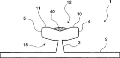
According to one aspect of the present invention, a kind of connector of throwing off of flooring panelling of the lamination that is used to assemble and seal a flooring system is provided, described flooring system is used for forming at the top of a supporting construction temporary transient or permanent lamination flooring surface, described connector comprises: a substrate, this substrate have a upper surface and a soffit; An extension that vertically extends from described substrate, wherein said extension comprise a vertical supporting member and at least one horizontal flanges, described at least one horizontal flanges be configured as with the oblique angle part of relative substrate with can releasably cooperate to form vertical a connection with the groove in the edge of flooring panelling; At least one ridge mountain range, vertically extend from the either side that described substrate and described extension separate in described ridge mountain range, and described at least one ridge mountain range is configured as in the basal surface with the flooring panelling groove and releasably cooperates to form a level and be connected; With a seal, the sealing part is connected with a element in described substrate, described extension and described at least one ridge mountain range; When at least two flooring panellings used connector to connect, final visible flooring surface comprised the only wearing face at the top of described panelling.
Preferably, at least one flange is along being parallel to the direction of aforesaid substrate by above-mentioned extension projection.
Preferably, above-mentioned seal is connected to described at least one flange.
Preferably, described flange comprises a top surface, and described seal is connected with the top surface of described flange.
Preferably, described flange comprises a far-end, and described seal is connected with the far-end of described flange.
Preferably, above-mentioned seal is connected with described at least one ridge mountain range.
Preferably, also have the groove between above-mentioned extension and aforesaid substrate, and above-mentioned seal is connected with described at least one groove.
Preferably, above-mentioned extension has supporting and flange, and above-mentioned extension also has the breach between supporting and flange, and above-mentioned seal is connected with described breach.
Preferably, also have the projection that stretches out by the distal part of above-mentioned extension along perpendicular to the aforesaid substrate direction, and above-mentioned seal is connected with above-mentioned projection.
Preferably, above-mentioned connector is along a central axis symmetry.
Preferably, the size of above-mentioned connector with a longitudinal axis and described extension is greater than in the size that is parallel to longitudinal axis direction upper substrate.
Preferably, aforesaid substrate and above-mentioned extension have selection from following material: filling plastics, filling plastics not, rubber, Wood composite material, pottery, metal, and their combination.
Preferably, above-mentioned seal has selection from following sealant: film, adhesive tape, liquid and paraffin material.
According to another aspect of the present invention, the method of the connector of throwing off of the flooring panelling of the lamination that a kind of manufacturing is used to assemble and seal a flooring system is provided, described flooring system is used for forming at the top of a supporting construction temporary transient or permanent lamination flooring surface, described method comprises: push a substrate, this substrate has a upper surface and a soffit; Push an extension that comes out from described substrate vertical extent, wherein said extension comprises that a vertical supporting member and at least one horizontal flanges, described at least one horizontal flanges are configured as with the oblique angle part of relative substrate and can releasably cooperate with the groove in the edge of flooring panelling; Push at least one ridge mountain range, vertically extend from the either side that described base portion and described extension separate in described ridge mountain range, and described at least one ridge mountain range is configured as a groove in the basal surface with the flooring panelling and releasably cooperates to form a level and be connected; With a seal is connected with a element in described substrate, described extension and described at least one ridge mountain range.
Preferably, above-mentioned extruding comprises along described at least one flange of direction extruding that is parallel to substrate.
Preferably, above-mentioned connection comprises above-mentioned seal and above-mentioned flange is coupled together.
Preferably, above-mentioned extruding is included in pressure ridge mountain range on the substrate of connector.
Preferably, above-mentioned connection comprises the top surface of above-mentioned seal and above-mentioned flange is coupled together.
Preferably, above-mentioned connection comprises above-mentioned seal and above-mentioned ridge mountain range is coupled together.
Preferably, above-mentioned extruding is included between extension and the substrate and pushes groove, and above-mentioned connection comprises above-mentioned seal and above-mentioned groove are coupled together.
Preferably, above-mentioned extruding comprises the extension of compression connector, makes it have a supporting member, a flange, and the breach between supporting member and flange, and above-mentioned connection comprises above-mentioned seal and above-mentioned breach are coupled together.
Preferably, above-mentioned extruding also comprises extrusion lug, and this projection is along stretching out perpendicular to the direction of the aforesaid substrate distal part from extension, and above-mentioned connection comprises above-mentioned seal and above-mentioned projection are coupled together.
Further advantage of the present invention is that panelling can arbitrary orientation when mounted, and does not need plant-manufactured slip feather of mechanical alteration or groove profile.Panelling can be made (the slip feather profile does not need machine) with the mode of favorable cost like this.Need the material quantity (about 3.18mm is wide) of machine-building slip feather profile to machine away.Cause cost to reduce greatly like this, this is owing to cancelled the required instrument of processing slip feather profile.Also have, what increased 3.18mm like this can sell the zone only.Form the material (about 3.18mm is wide) that the slip feather profile machines away in the past and be processed into the groove profile now.Make groove,, also increased superficial area as relative with slip feather.Bigger superficial area causes bigger income, because superficial area can be used for selling, rather than machines away and abandons.
Seam " protuberance " or " Cheng Feng " that is caused by typical slip feather and groove system also eliminated in system of the present invention.When moisture by the floor above infiltration seam or when arriving seam by the bottom surface of flooring panelling, seam profile protuberance.Explanation in passing, the size of slip feather profile will increase, and the size of groove profile will be shunk.Cause the variation (thickness increase) of whole panel thickness in the seaming zone like this.Consequently on seaming zone direct " alarmming ".Because the present invention uses the joint between two panellings of connector formation that have flange, and flange does not re-use the material manufacturing that absorbs moisture content.Therefore, the slip feather that has expanded when not absorbed moisture here is the problem that " so alarmming " exists when no longer being to use system of the present invention.
Also have, the seal that is connected to connector has prevented that moisture from entering seam, perhaps the interface that enters connector 1 panelling by the back side or the bottom surface of panelling.Because seal provides moisture blocking layer, moisture does not damage the chance of panelling again.
Description of drawings
Read the explanation of following non-restrictive example and with reference to the accompanying drawings, will be better appreciated by the present invention.In each figure, similar parts are used identical label.
Fig. 1 illustrates an embodiment of connector of the present invention and seal;
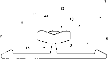
Fig. 2 illustrates another embodiment of connector of the present invention and seal;
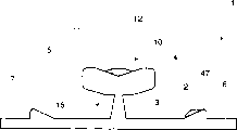
Fig. 3 illustrates another implementation column of connector of the present invention and seal;
Fig. 4 illustrates another embodiment of connector of the present invention and seal;
Fig. 5 illustrates another embodiment of connector of the present invention and seal;
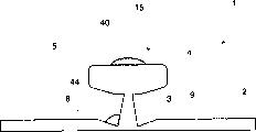
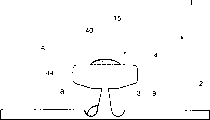
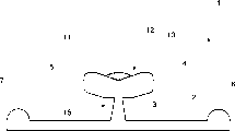
Fig. 6 illustrates the most preferred embodiment of connector of the present invention and seal;
Fig. 7 illustrates another embodiment of connector of the present invention and seal;
Fig. 8 illustrates another embodiment of connector of the present invention and seal;
Fig. 9 illustrates another embodiment of connector of the present invention and seal;
Figure 10 illustrates another embodiment of connector of the present invention and seal;
Figure 11 illustrates another embodiment of connector of the present invention and seal;
Figure 12 illustrates another embodiment of connector of the present invention and seal;
Figure 13 illustrates another embodiment of connector of the present invention and seal;
Figure 14 illustrates special most preferred embodiment (the scale 9X of connector of the present invention and seal; 100=25.4mm);
Figure 15 illustrates the phantom drawing of the most preferred embodiment of connector of the present invention;
Figure 16 illustrates another embodiment of connector of the present invention and seal;
Figure 17 illustrates another embodiment of connector of the present invention and seal;
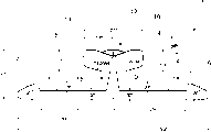
Figure 18 illustrates the most preferred embodiment of connector of the present invention and seal and the most preferred embodiment of panelling of the present invention;
Figure 19 A is that layer has the top view of the panelling of bevel groove overleaf;
Figure 19 B is the end-view of Figure 19 A panelling;
Figure 20 A is the top view of connector that has the seal of the end of inclination and extension;
Figure 20 B is the end-view of connector shown in Figure 20 A and seal;
Figure 20 C is the lateral view of connector shown in Figure 20 A and the 20B and seal;
Figure 21 is the top view of the part load segment of floor covering, and it has square panelling and has the connector of angled end;
Figure 22 is the top view of the part load segment of floor covering, and it has square and triangle panelling and the connector that has angled end;
Figure 23 is the top view of the part load segment of floor covering, and it has rectangular panels, horizontal connector and connector longitudinally;
The top view of the connector that Figure 24 A is horizontal, it has the seal and the ridge mountain range seal of extension;
Figure 24 B is the end-view of lateral connector shown in Figure 24 A;
Figure 24 C is the lateral view of lateral connector shown in Figure 24 A and the 24B;
Figure 25 is the lateral view with the lateral connector of two vertical connectors and seal assembling, the vertical end-view of connector shown in the figure, and all connectors have extension and ridge mountain range seal;
Figure 26 A has the top view of the rectangular panels of groove completely;
Figure 26 B is the end-view of panelling shown in Figure 26 A;
Figure 27 is the top view of the floor system of part assembling, and it has hexagon and triangle panelling.
The specific embodiment
Yet it should be noted that accompanying drawing only illustrates typical embodiment of the present invention, thereby should not consider to be subjected to the restriction of this scope, because the present invention can allow other equivalent embodiment.
In a most preferred embodiment, the purpose of system of the present invention is a decorative laminate flooring panelling, square block, rectangular tiles etc., they have wear-resisting end face, middle matrix or reinforcing material under end face, and optional back layer, matrix material and in order to contact in the middle of it is connected to bearing surface or existing floor or ground.
The wear-resisting end face of panelling of the present invention is preferably decorative laminate or hot compaction laminate.These panellings commercial production and are widely used in builing industry and furniture industry for many years, as counter top and desktop, and bathroom and kitchen working surface, wall slab, dividing plate and door.Decorative laminate is composite material that is formed by a series of interlayer compactings or the structure that has the unanimity of surface decoration layer, and decorative layer can be simple monochrome, to complicated embossing simulation wood grain.
More particularly, the decorative laminate that uses among the present invention has the cardboard of multi-layer synthetic resin dipping usually, becomes consistent structure through hot pressing.In normal practice, the decorative laminate board component comprises that the bottom surface upwards has the heartwood of the cardboard of one or more layers dipping phenol resin, lays the decorative cardboard of dipping melamine resin and/or the surface layer of dipping melamine resin on it.The function of heartwood or base member provides the rigidity of laminate, and has hard matrix usually, and it is that the lamination step that is in or be not in beginning forms before.Before lamination, the paperboard grade (stock) phenol of heartwood element and formaldehyde ethanolic solution dipping, or formaldehyde pretreating agent impregnation drying and partly solidified in air oven, and finally cut into plate.The example of this matrix or heartwood element is as follows: the kraft of (1) one group 40.8 to 68.1 (kilogram/make) fully floods with bonding with completely crued in fact phenol resin, and it has been converted into the thermosetting state when the lamination step of beginning; (2) plastic laminates of precuring, for example, glass-fiber reinforced thermo-setting polyester resin layer pressing plate or similar products; (3) timber products, for example, hard plate, fiberboard, wooden slag plate, particle board, veneer or similar products; (4) mineral substrate, for example, cement-sheet asbestos, slate, gypsum plank, or similar products; (5) plastics dipping plate; (6) plastics/composite wooden material; (7) plastic composite; (8) sealing born of the same parents lattice polyurethanes foam material, for example RIM foamed material; (9) urethanes dipping plate; (10) combination of these matrixes; (11) can satisfy any material that matrix or heartwood are wished function.
The common function of the decorative panel that uses in the panelling of the present invention is to give laminate tempting outward appearance, and the characteristic (being chemical reagent resistance, heat resistance, light resistance and shatter-proof and abrasion resistance) that gives panel surface.The chemical cellulose paper of the pigment filling of high-quality typically 50 to 125 ream weights of decorative panel uses melamine-formaldehyde resin ethanolic solution dipping, dry and partly solidified, and finally cuts into plate.Decorative panel can be monochromatic or have decorative design or pattern, or the optical reproduction natural materials, as timber, and marble, leather etc.As mentioned above, decorative panel and/or sheet surface layer can flood melamine resin.
The acquisition methods of making the decorative laminate that uses in the panelling of the present invention normally, but be not limited to: heartwood and the decorative panel of between galvinized steel or stainless-steel sheet, placing resin impregnation, and make laminated stack stand temperature by about 66 ℃ to 260 ℃ and pressure by about 5.52 to about 11.03MPa, through adequate time with compacted lift pressing plate and cured resin (usually about 25min to 1h).Cause resin to flow in cardboard like this, curing and compacting sheet material become composite material or consistent lamination material, are called high pressure decorative laminate (HPDL) in technology.Can be shaped simultaneously more than a laminate, method is to insert the sheet material of the assembling of one group of lamination, and each assembly is with isolating sheet material separately, and independent laminate separated after it can make compacting.At last, decorative laminate is further handled and is bonded to the enhancing matrix usually, for example, in to the fiberboard of high density, timber/plastic composite, timber, veneer, hard plate, sheet asbestos, particle board, pottery, filling and filling plastics not, sealing born of the same parents' lattice rigid foam or similar products.If cushioning effect is wished, strengthen born of the same parents' lattice foamed material that matrix can comprise open type.
The decorative laminate that uses in the practice of the present invention also can obtain in order to following method: between galvinized steel or stainless-steel sheet, place the heartwood and the decorative panel of resin impregnation, and make laminated stack stand temperature by about 66 ℃ to about 260 ℃ and pressure by be lower than about 5.52 to about 11.03MPa through adequate time with compacted lift pressing plate and cured resin.Cause resin in cardboard, to flow, solidify like this, and compacting sheet material becomes composite material and consistent lamination material, in technology, be called low pressure decorative laminate (LPDL).
In addition, according to an embodiment, enhancing matrix of the present invention can be with any suitable squeezable thermoplastic manufacturing, as long as its structure and mechanical property are wish required through the end purposes.Special is, preferably making matrix have compression set is same as or is better than common middle density or high density fiberboard or particle board (its compression set is measured according to ASTMF970, it is from the minimizing of the thickness function as compressive stress), preferably, thickness minimizing under 13.79MPa mostly is 0.254mm most, be 0.127mm more preferably, and be most preferably 0.0254mm.
The enhancing matrix that uses in the present invention practice may have one or more and select constituent element from following group: hard carbamate (for example RIM foamed material), poly-(acrylonitrile-butadiene-styrene (ABS)) resin, hereinafter to be referred as ABS resin, for example, flame-proof ABS resin and glass fiber filling ABS resin; Merlon; HTPS, polystyrene, polydiphenyl ether (PPO)) and polyvinyl chloride (PVC).Preferably, strengthen matrix and form, contain, but be not limited to above-mentioned one or more polymer by the hybrid resin system.In addition, these polymer can be filling or not filling, though from the viewpoint of impact strength and physical property, the polymer of filling is best.Preferred filler comprises calcium carbonate, French chalk, silica, glass fiber, alumina and wollastonite, even more preferably calcium carbonate and wollastonite, most preferably calcium carbonate.The unrestricted example of reinforcing agent comprises inorganic or macromolecular organic compound, for example, and glass microballoon, glass fiber, asbestos, boron fibre, carbon fiber and graphite fibre, whisker, quartz and silicon dioxide fibre, alumina fibre, melting fiber material and organic fiber.When using these common ingredients, the scope of their common additions for the total amount that strengthens base member by about 0.01 to about 50% weight, preferably the total amount of element by about 1 to about 25% weight.
Additional optional layer can be inserted between heartwood element and the combination with decorative surfaces element, at the back side that strengthens base member or on the combination with decorative surfaces element.Should be appreciated that backing layer and/or decorative layer can perhaps be laid with any suitable method with strengthening the primary element co-extrusion pressure after pressing steps.
According to the panelling of one embodiment of the present of invention, waterproof preferably more preferably comes down to watertight.The same with common flooring panelling, this panelling has decorative layer, substrate layer and backing layer.Decorative layer and backing layer bond to base layer to form panelling with common mode respectively, and according to most preferred embodiment of the present invention, it strengthens matrix material is fiberboard, and backing layer has hydrophobicity water sealed layer and the 3 layers of kraft that fluosite floods that made progress by the bottom surface.The same with the base resin dipping of decorative layer, the end face resin impregnation layer of backing layer also is used for base layer bonding.The hydrophobicity water sealed layer can be DYLARK one compounds.DYLARK is a kind of styrene-maleic anhydride copolymer, is made by NOVAChemica/s Inc. company.DYLARK demonstrates the cementability with phenol resin impregnated kraft paper excellence.The cementability of this excellence can think to exist in the maleic anhydride of DYLARK copolymer the result of carboxyl.The very stable laminate of the bonding generation of carboxyl and phenol resin.Though DYLARK is the preferred material of the bottom of backing layer, under the condition that does not break away from spirit of the present invention, also can use other function copolymer identical with structure.Not only wish to prevent moisture content infiltration backing layer, the moisture when also wishing to keep the original manufacturing of panelling is curled to prevent panelling.
In addition, though used the fluosite impregnated kraft paper, under the condition that does not break away from spirit of the present invention, also can use other Tetefol (or similar material) according to most preferred embodiment.The resin impregnation layer remains in this backing layer with balance and is present in resin impregnation layer in the decorative layer usually, and it may engage use with backing layer.In other words, resin impregnation layer in the decorative layer and backing layer are similarly expanded by Temperature Influence and shrink, to keep the smooth in fact shape of flooring panelling.If do not add the resin impregnation layer in backing layer, then the speed of the expansion of decorative layer and contraction is different from backing layer.Can cause panelling to curl like this in undesirable mode.So, the person skilled in the art should be appreciated that, can change the phenol resin layer to keep the equilibrium relation between backing layer and the decorative layer.
As described in one embodiment of the present of invention, base layer is poly-(propylene-C-butadiene-styrene) (ABS) foamed material, and the structure of backing layer and base layer provides the panelling of watertight, and it is insensitive to the hostile environment condition that runs in the certain environment of being everlasting.Particularly ABS base layer and styrene maleic anhydride copolymer have formed moisture blocking layer, and its nurse tree impregnate with tallow layer is not subjected to the deleterious effects of moisture.
Known technology manufacturing in the above-mentioned flooring panelling operation technique.During fabrication, panelling can be processed the suitable breach of formation on the edge, perhaps preferably, the breach that at least two edges have is that panelling forms when making, therefore reduced and made the required quantity of material of panelling, in addition, according to an embodiment, panelling of the present invention can use injection-molded manufactured, its whole edges once-forming.
Connector of the present invention illustrates with a series of embodiment.Now, wherein represent the parts of connector of the present invention, the end-view of connector 1 different embodiment is shown with identical figure number referring to Fig. 1-18.Connector 1 has substrate 2 and extension 15.Substrate 2 for smooth in fact parts in order to be parked in floor or the surface that the panelling that is assembled and connector cover.The extension heart is a T shape projection, has vertical support 3 and two horizontal flanges 4 and 5.Supporting 3 is that the vertical component and the flange 4 and 5 of T shape is the horizontal-extending part at T shape top.As shown in many explanatory embodiment, connector 1 has ridge mountain range 6 and 7, and it is vertically stretched out by substrate 2, near the distal edge of substrate 2 with supporting 3 to substrate 2 be connected the center away from.In other embodiments, connector 1 has groove 8 and 9, is positioned on the upper surface of substrate 2, near the relative side of supporting 3.Some embodiment of connector 1 has vertically extending projection 10 and 11.In certain embodiments, between vertically extending projection 10 and 11, be provided with slit 12 at the top of T shape extension.Some embodiment of connector also have breach 13 and 14, be positioned at flange 4 and 5 and the supporting 3 junction near-ends below.Wish that the connector 1 of system of the present invention has T shape extension, ridge mountain range 6 and 7, and panelling has breach and groove, so that make two panellings use the gentle vertical modes of connector water removably to interconnect, and need not use glue or other bonding agent.
Seal is made with connector 1, and seal is the key sealant that is connected to connector 1.In different embodiment, sealant material comprises film, adhesive tape, liquid, paraffin etc.Sealant material is coated on the connector 1, has different thickness, applies in special district and with diverse ways.
Referring to Fig. 6, connector of the present invention 1 drawing in side sectional elevation and the end-view that have seal are shown.In the present embodiment, seal is the seal 40 of extension.Extend the slit 12 that seal 40 is positioned at extension 15 tops of connector 1, by the whole length of connector 1.As shown in figure 18, when using two panellings 20 of connector assembling of Fig. 6, extend seal 40 distortion and compression between two panellings 20, and the seam 50 between the connector 1 salable panelling 20.The volume that extends the sealant in the seal is correct amount just, thereby makes sealant fit into the space that connector 1 and seam 50 following two panellings limit, and the edge that can not promote panelling upwards (alarmming).
In the embodiment that replaces, seal is connected to the other parts of connector 1.As shown in Figure 1, lip seal 41 is connected to the far-end of flange 4, and during assembling, seal provides the flange 4 of panelling 20 and the sealing (seeing Figure 18) between the groove 24.
As shown in Figure 2, several base plate seals parts are connected to the end face of the substrate 2 of connector 1.According to material and the intended purpose used, can use one or more base plate seals parts.During assembling, the base plate seals part has formed the sealing (seeing Figure 18) between the backing layer surface 23 of the end face of substrate 2 of connector 1 and panelling 20.
As shown in Figure 3, support seal 45 is connected in the supporting 3 of extension 15 of connector 1.During assembling, seal provides and has supported 3 and form sealing (seeing Figure 18) between the distal portions of panelling 20 of downside of groove 24.Certainly, the volume of support seal 45 must be enough little, so that panelling 20 can be cooperated with connector 1 fully, prevents the seam 50 interior spaces that produce of final assembly.
Referring to Fig. 7, ridge mountain range seal 47 is connected to the ridge mountain range 6 of connector 1.During assembling, seal provides the sealing (seeing Figure 18) between the groove 25 that forms on the backing layer surface 23 of ridge mountain range 6 and panelling 20.Ridge mountain range seal 47 can be connected to the arbitrary side or the two sides in ridge mountain range 6.Should use the encapsulant of correct number, to realize sealing and to allow ridge mountain range 6 when assembling, to enter fast in the groove 25.
As shown in Figure 8, groove seal 44 is connected to the substrate 2 of connector 1 and supports in the groove 8 between 3.During assembling, seal provides the sealing (seeing Figure 18) between the following corner of groove 8 and panelling 20.Groove 8 guarantees the encapsulant filling space of quantity sufficients, and does not destroy cooperating fully of panelling 20 and connector 1.
As shown in figure 11, breach seal 46 is connected to the flange 4 of connector 1 and supports in the breach 13 between 3.During assembling, seal provides the sealing (seeing Figure 18) between the lower lip of groove 24 of breach 13 and panelling 20.Breach 13 has guaranteed the encapsulant filling space of quantity sufficient, and does not destroy cooperating fully of panelling 20 and connector 1.
Should be appreciated that Fig. 1-18 is not intended to limit the scope of the invention, but provided the embodiment of exemplary, comprise the most preferred embodiment of the various parts of novel connector of the present invention.Really, can use the various combinations of the different embodiment of the various individual components of connector, i.e. the shape of the various substrates 2 shown in, for example, but be not limited to Fig. 1,2,7,8, shown in 9,10,11,12 grades, can with for example, but be not limited to Fig. 1,2,3,5,6,16, the various embodiment of the extension of 17,18 grades use together, even strict combined shaped in the drawings may be not shown.Preferably, the height of connector is less than 6.1mm.
Connector of the present invention can be used and select from the material manufacturing of group down: filling or not filling plastics, rubber, Wood composite material, pottery, metal and their combination.Wish that when using with preferred lamination flooring panelling, connector of the present invention is by metal or plastics manufacturing.Different according to material and size, connector can operation technique on known technology manufacturing, for example, connector preferably is manufactured from aluminium.
Panelling of the present invention has within it the breach that forms, and it is configured as can accept connector, and when panelling engaged, the flooring surface that end face can be seen only was made up of wear-resisting end face like this, in other words, and decorative layer preferably.The projection of connector and the breach of panelling form like this, when using connector of the present invention, two panellings join a time-out to, panelling vertically joins to together, if promptly panelling engages in their edge, the edge of relative panelling can be not mutually about (vertically) move, thereby level between the two is provided and seam uniformly.For example, in best example, in case connect, the joint of panelling has been offset their their mutual moving on the plane of being stretched out by supports vertical and its vertical direction.
In a concrete most preferred embodiment, except vertical connection, panelling and connector are shaped like this, to provide adjacent panelling to connect in the level of their edges, in other words, if two panellings connect at their edge, the edge does not have any mutual moving horizontally, and causes the gap between the adjacent panel.For example, according to an embodiment, in case connect, the joint of panelling has offseted their mutual moving on the horizontal direction of area supported and its parallel direction.
Stated the various unrestricted embodiment of connector of the present invention, though of no use illustrating, panelling of the present invention must be configured as, and is for example corresponding with these connectors, to reach advantage of the present invention.Should be appreciated that panelling can be shaped as with connector is strict and cooperates or non-strict cooperation, as long as can reach advantage of the present invention.For example, wishing the occasion of permanent structure, an embodiment allows to stay the gap with the glue between accumulation panelling and the connector, may be suitable like this.In addition, when using certain to strengthen matrix material, may not wish that panelling and connector strictness fit together, when particularly wishing temporary structure.For example, can allow some spaces between the projection of connector and some part of breach, as long as reach advantage of the present invention, particularly final floor only has the wear-resisting end face of the uniform seam of band level to be seen.
Panelling is made such, make them removably connect connector of the present invention, in other words, when connector and panelling are fixably attached to together when realizing the function on flooring surface, if wish, can pull down panelling, method is to rise panelling and pull out interconnecting of panelling-decomposition panelling/connector by connector.
According to an embodiment, panelling of the present invention is made such, and when using connector of the present invention that they are connected together, they form closely horizontal joint uniformly between the panelling through being everlasting.Make like this according to the panelling of most preferred embodiment, the breach on each panelling bottom surface or the degree of depth of groove are often left wear-resisting end face certain distance.As mentioned above, these breach or groove are configured as can accept the projection that the substrate by connector (preferably guide rail) stretches out, so that removably level connects two panellings to together.Like this, at tie point, two panellings rest on the connector.Therefore, even supporting construction or ground are uneven or be not level, seam often is closely, uniformly and level.Like this, even, when two panellings engage, also can obtain uniform horizontal joint,, the degree of depth of breach in each panelling bottom surface or groove has because being configured as with a certain distance from wear-resisting end face if the thickness of panelling changes.Therefore, the wear-resisting end face of two adjacent panellings often remains on the identical level, promptly with a certain distance from the substrate projection of connector.Preferably, the thickness range of the panelling of system of the present invention by about 6.1mm to about 8.1mm.According to another embodiment, the thickness of inserting is less than 25.4mm.
System of the present invention also provides panelling, and it has utilized the wear-resisting end face of in fact all making, thereby has guaranteed to surpass the economic advantages of many prior art systems.Use system of the present invention, need machine to reduce greatly with the total amount of removing any fabrication portion and paying ornamental wear-resisting end face.Therefore the ornamental wear-resisting end faces of in fact all making all can be sold to end user-the eliminated discarded object that exists in the prior art systems.Consequently the total square feet of quantity on the salable floor of plant produced increases and the price reduction.
In addition, connector of the present invention is not to be fixed on the panelling in factory, does not therefore need to re-use bonding agent or other securing member, thereby has reduced Master Cost, and laboring fee is used and manufacturing time.In a most preferred embodiment, use the injection molding technique manufacturing to have the panelling that all needs breach.In another most preferred embodiment, the enhancing matrix of the centre of panelling pushes, and it is machines to form breach that two edges are only arranged, and other two edges of arranging along machining direction form when being extruding.Above-mentioned two embodiment provide additional saving, and this is that Here it is does not produce because the matrix material amount of the centre of using reduces.
System of the present invention also provides existing slip feather and the groove system panelling little to susceptibility to damage, for example.As everyone knows, in transportation, operation and even assembling and when decomposing, the slip feather of panelling is to damaging sensitivity.If slip feather damages or distortion, it just can not engage with the groove of adjacent panel, thereby is scrapped.Panelling of the present invention does not have slip feather ,-they only have breach or groove.In operation, transportation when assembling and decomposition, if not impossible, also is to be difficult to damage breach and groove.Therefore, panelling of the present invention is more durable than the panelling of many prior aries.Use more remarkable in " floating floor " surface and temporary transient flooring configuration aspects that needs are repeatedly dismantled and ressembled than the advantage of panelling.The connector that system of the present invention provides (preferably being made of metal), quite tough and tensile, and change easily and price cheaper than new panelling.System of the present invention is eliminated, and also is to reduce the panelling damage greatly to the danger that lost efficacy.
The floor surface that floor system of the present invention provides is repaired easily and/or is changed.The panelling of system of the present invention does not need unidirectional laying program, therefore, needs only the adjacent panelling of at first removing on any direction, with regard to panelling dismountable and the replacing operation.Adjacent panelling can be removed on the direction with minimal number panelling, thereby has simplified dismounting and replacing process.System of the present invention greatly reduces the time and the workload of removing and changing panelling.In addition, because the floor can be built on multi-direction, a plurality of workmans can build the different piece of independent floor surface simultaneously.According to an assembling process, panelling is laid on the core of floor space and is outwards increased by the center.Surface, large tracts of land floor is being installed, aspect, space, retail market for example, this laying method advantageous particularly.
The panelling of system of the present invention provides the aesthstic flexibility bigger than prior art panelling.For example, panelling be not the right hand or left-hand to, promptly unidirectional, but multidirectional, because each edge is identical, each independent panelling can be placed in the floor surface and build in mode the most attractive in appearance, moreover the panelling of system of the present invention has the flexibility of design and building veneer type floor surface, for example, known, the common panelling of making, its fiber is arranged along machining direction; Yet,, change easily to form parquet floor or any fiber design in the lip-deep machine direction of floor file because panelling of the present invention is a multidirectional.
The panelling of system of the present invention has also reduced the discarded object in the building of floor.When using panelling of the present invention, promptly each panelling manufactures in that all marginal belts are fluted, finishes any panelling part that keeps to the headwall wall after the floor and still can be used for finishing another part to headwall wall floor thereby make.
The panelling of system of the present invention is to make like this, in order to assemble two panellings to together, does not need to keep a panelling to put in place with respect to another panelling inclination and the new panelling of oblique cutting.The fact is can oppress them to be bonded with each other together when two panellings are laid at grade, this method has very big advantage aspect some part on building flooring surface, these parts are subjected to different physical interfaces, for example challenge of interface between floor surface and the fireplace.
Referring now to Fig. 6,, the most preferred embodiment of connector 1 of the present invention, it has substrate 2, and extension 15 stretches out the ridge mountain range 6 of keeping at a distance and 7 and they are by substrate 2 vertical protrusion by extension 15 arbitrary sides. Ridge mountain range 6 and 7 best tops are rounded, as shown in the figure, and downward-sloping tapering, are promptly terminally highly being reduced when mobile to it by substrate 2 centers.Therefore, the most maximum near the vertically extending distance of the ridge mountain range part of substrate 2 centers and extension 15.
The special most preferred embodiment of connector 1 of the present invention is shown in Figure 14.The scale of Figure 14 is 9 times of full-size(d).Yet should be appreciated that though not shown, the substrate 2 of connector 1 can be made like this, makes it not contact supporting construction, promptly connector is contained fully by the panelling of two joints.
Referring to Figure 19 A and 19B, the top view and the end-view of square panelling 20 is shown respectively.Panelling 20 has wear-resisting end face 21, middle base layer 22 and backing layer surface 23.In an illustrated embodiment, panelling 20 has 4 grooves 24 altogether in each middle base layer 22 of its 4 sides.In addition.Panelling 20 has 4 grooves 25 on backing layer surface 23, they are parallel to 4 sides of panelling and keep little distance with each side.(not shown) in the embodiment of a replacement.Be in 2 of formation or more groove 25 on the backing layer surface 23 in each side of adjacency panelling.Certainly, in this embodiment, connector 1 has 2 or more (6 s' or 7) ridge mountain range on each side.
Connector shown in Figure 20 A-20C is used for panelling shown in connection layout 19A and the 19B.The top view of connector 1 is shown, end-view and lateral view respectively.As previously mentioned, connector 1 has substrate 2 and extension 15.Substrate 2 has the ridge mountain range 6 and 7 on upper surface.Extension 15 has 3 and two flanges 4 of supporting and 5.Extension 15 has slit 12 at its top, is connected with the seal 40 of extension in slit 12.The seal 40 of extension extends to the whole length of connector, and in certain embodiments, the good sealing (seeing Figure 21 and following) in joint between the connector when finally assembling to keep floor system that it extends beyond its end.The two ends of connector 1 tilt 45 ° (seeing Figure 20 A) to produce end face 16.Because end face 16 cuttings in each same side are at 45, form 90 ° of angle points at the middle part of every terminal adapter.In the embodiment that replaces, seal is connected to the end face 16 of connector.
The assembled portion on floor has the square panelling 20 that connects together with connector 1 as shown in figure 21.The end face 16 of two connectors 1 is in contact with one another placement, and connector is fixed on the adjacent side of independent panelling 20.The advantage of this shape is that the wear-resisting end face of panelling is connected device 1 supporting fully, even at the corner place of connector 1 intersection.Also have, because the seal 40 of extension extends to the other end by an end of connector 1, the seal 40 of extension is in contact with one another, thereby in the fusion of corner place, thereby guaranteed the sealing completely at corner place.
In the embodiment of a replacement, some panelling 20 is made triangle, and triangle has increased the decoration ability of the floor covering of assembling.A kind of possible arrangement of the decorative parts on floor is shown in Figure 22.Certainly, require different connector 1 to engage with the triangle panelling.They must have end face and cut sth. askew 22.5 ° in some cases, and cut sth. askew 45 ° in other cases.In other embodiments, panelling has square, rectangle, triangle, pentagon, hexagon and octagon geometry.According to assembly system of the present invention, might assemble panelling with these geometries, because work as panelling at ordinary times on subfloor supporting upper berth, can fielded panel and connector.With Figure 27 is example, and the hexagon panelling on part assembling floor is shown.Its connector 1 is used for the connection between the panelling 20, and for for simplicity, connector 1 is not shown in the drawings.Panelling 20b is in the position that is connected with 20g with panelling 20f.Because panelling 20f and 20g assemble, they are paved in the subfloor supporting.The method of attachment of panelling 20b is that panelling 20b paves on bottom and towards panelling 20f and 20g slip panelling 20b.Realize simultaneously with the contact of panelling 20f and 20g and panelling 20b mates fast with the connector (not shown) between the panelling and is connected.Similarly, panelling 20a and panelling 20c are shown, the position that is connected of 20d and 20e.It is adjacent that panelling 20a is placed on the subfloor panelling with other, is in same plane with other panelling like this.Panelling 20a is subsequently towards panelling 20b, and 20c and 20d slide, up to contacting with panelling simultaneously.Because each connector 1 has one or more seals, seal is out of shape between connector 1 and panelling 20 and compresses in assembling process.
Figure 18 illustrates panelling/connector assembly.Panelling 20 and connector 1 enter the groove 24 of panelling 20 fast by protruding 4,5 of connector 1 and engage fast.The contact of beginning is to be inserted grooves 24 and carried out by flange 4,5.Further mutual when mobile when panelling 20 and connector 1, ridge mountain range 6,7 slides across the backing layer surface 23 of panelling.The top margin of the groove 24 of relative panelling 20 engages with the seal 40 of the extension of relative side.Because panelling 20 more is close to together to form seam 50, the seal 40 of extension is in the space internal strain that is limited by the slit 12 of the upper side of groove 24 and connector 1.When panelling 20 and connector 1 moved together fully, flange 4,5 stretched into groove 24 and ridge mountain range 6,7 fully and engages fast and enter groove 25.When final assembling, seal 40 abundant distortion and molding become a sealing in seam 50.By whole process, the substrate 2 of connector 1 still remains on the identical in fact plane with panelling 20.Because connector 1 remains on the identical plane with panelling 20 during assembling, and a panelling is engaged with a plurality of other panellings.This monoplane " engages " assembling process fast and makes the panelling that might use above-mentioned different geometries.
Referring to Figure 23, the shape that another kind of floor covering of the present invention is used is shown, it has the panelling of rectangle.In the present embodiment, panelling 20 uses two types connector.Vertical connector 30 and lateral connector 31.In one embodiment of the invention, vertically connector 30 engages several panellings 20 fast, thereby it is more much longer in the vertical than any given panelling.In another embodiment of the present invention, vertically connector 30 is roughly identical with panelling length in the vertical.The length of the lateral connector 31 roughly width with panelling 20 is identical.Lateral connector 31 extends with the right angle between adjacent two parallel vertical connectors 30.In shape shown in Figure 23, every group of panelling 20 vertically extending end-to-end, is offset at the panelling of vertically arranging end-to-end with every adjacent set.Because panelling is in the different position of the specific arbitrary side of vertical connector, the strength ratio of this assembly is much bigger by the more equally distributed assembly of assembly joint.If it is not skew that the end of whole panellings walks to another row one, then the reduction on floor can appear at 4 corner region, and adjacent here lateral connector 31 engages independent vertical connector 30.By the same token, in certain embodiments of the present invention, vertically the end of connector 30 does not overlap with vertical end of panelling 20, and connector strides across at least two adjacent panellings 20 like this.
Referring to Figure 24 A to 24C, the top view and the lateral view of lateral connector 31 is shown respectively.Similar to above-mentioned connector, lateral connector 31 has substrate 2 and extension 15.Extension 15 has supporting 3 and flange 4 and 5.The seal 40 of extension is connected to the top of extension 15.Lateral connector 31 also has the ridge mountain range 6 and 7 that is positioned on substrate 2 opposite ends.Ridge sandfly seal 47 is connected to the top of ridge mountain range 6 and 7.Lateral connector 31 important characteristic are that extension 15 is longer than substrate 2, and the two ends of extension 15 extend to outside the substrate 2 like this.In Figure 24 C, have grooving 32 and 33 on the two ends of extension 15.Grooving 32 and 33 shape and size are negative-appearing images of ridge mountain range 6 and 7, and lateral connector 31 is cooperated with vertical connector 30 with the right angle.
Figure 25 illustrates the horizontal assembling drawing that goes out connector 31 and two vertical connectors 30.Vertically connector 30 is an end-view, and lateral connector 31 is a lateral view.Vertically connector 30 parallel placements, and lateral connector 31 is vertically between the connector 30 and at right angles.The grooving 32,33 of lateral connector 31 be positioned at vertical connector 30 ridge mountain range 6,7 directly over.Sealing between the grooving 32,33 of ridge mountain range seal 47 formation lateral connectors 31 and the ridge mountain range 6,7 of each vertical connector 30.As mentioned above, the extension 15 of lateral connector 31 extends to the entire portion of its plate 2 of vertical connector 30.Horizontal and vertical connector 31 and 30 all has the seal 40 that is connected thereon.Panelling and connector device timing as shown in the figure, seal are placed on the seam 50 interior (seeing Figure 18) between the panelling.Almost completely center on the corner region of the periphery, particularly panelling of panelling.The possibility that seam 50 seals fully is because the extension 15 of lateral connector 31 extends to outside its substrate 2, and almost the flange 4,5 with vertical connector 30 contacts.Make the seal 40 of the extension of lateral connector 31 extend to the almost completely extremely vertically seal 40 of the extension of connector 30 like this.
Referring to Figure 26 A to 26B, the top view and the lateral view of rectangular panels is shown.This panelling 20 is particularly suitable for the described vertical and horizontal connector assembling of Figure 23 to 25.Identical with aforesaid panelling, this panelling has wear-resisting end face 21, middle matrix 22 and backing layer surface 23.The flange 4,5 that panelling 20 also has groove 24 and connector 30,31 cooperates.Groove 24 extends along the periphery of panelling 20 fully.Panelling 20 also has 4 sides arrangements that 4 grooves 25 are parallel to panelling.Groove 25 is to cut out or make on the bottom surface of panelling 20 or backing layer surface 23.Groove 25 extends to another side by a side of panelling.The groove 25 of panelling 20 is used for cooperating with the vertical ridge mountain range 6 and 7 of the lateral connector 31 of connector 30.
Though floor system shown in above and parts disclosed special embodiment in detail can be used to obtain above illustrative purposes and advantage, should be appreciated that they only are the explanations for most preferred embodiment, rather than limit scope of the present invention.
Claims (22)
1. the connector of throwing off of the flooring panelling of a lamination that is used to assemble and seal a flooring system, described flooring system is used for forming at the top of a supporting construction temporary transient or permanent lamination flooring surface, and described connector comprises:
A substrate, this substrate have a upper surface and a soffit;
An extension that vertically extends from described substrate, wherein said extension comprise a vertical supporting member and at least one horizontal flanges, described at least one horizontal flanges be configured as with the oblique angle part of relative substrate with can releasably cooperate to form vertical a connection with the groove in the edge of flooring panelling;
At least one ridge mountain range, vertically extend from the either side that described substrate and described extension separate in described ridge mountain range, and described at least one ridge mountain range is configured as in the basal surface with the flooring panelling groove and releasably cooperates to form a level and be connected; With
A seal, the sealing part is connected with a element in described substrate, described extension and described at least one ridge mountain range;
When at least two flooring panellings used connector to connect, final visible flooring surface comprised the only wearing face at the top of described panelling.
2. according to the described connector of claim 1, it is characterized in that at least one flange is along being parallel to the direction of aforesaid substrate by above-mentioned extension projection.
3. according to the described connector of claim 2, it is characterized in that above-mentioned seal is connected to described at least one flange.
4. according to the connector of claim 3, it is characterized in that described flange comprises a top surface, described seal is connected with the top surface of described flange.
5. according to the connector of claim 3, it is characterized in that described flange comprises a far-end, described seal is connected with the far-end of described flange.
6. according to the described connector of claim 1, it is characterized in that above-mentioned seal is connected with described at least one ridge mountain range.
7. according to the described connector of claim 1, it is characterized in that, also have the groove between above-mentioned extension and aforesaid substrate, and above-mentioned seal is connected with described at least one groove.
8. according to the described connector of claim 1, it is characterized in that above-mentioned extension has supporting and flange, and above-mentioned extension also has the breach between supporting and flange, and above-mentioned seal is connected with described breach.
9. according to the described connector of claim 1, it is characterized in that also having the projection that stretches out by the distal part of above-mentioned extension along perpendicular to the aforesaid substrate direction, and above-mentioned seal is connected with above-mentioned projection.
10. according to the described connector of claim 1, it is characterized in that above-mentioned connector is along a central axis symmetry.
11., it is characterized in that size that above-mentioned connector has a longitudinal axis and a described extension is greater than in the size that is parallel to longitudinal axis direction upper substrate according to the described connector of claim 1.
12., it is characterized in that aforesaid substrate and above-mentioned extension have selection from following material: filling plastics, filling plastics not, rubber, Wood composite material, pottery, metal, and their combination according to the described connector of claim 1.
13., it is characterized in that above-mentioned seal has selection from following sealant: film, adhesive tape, liquid and paraffin material according to the described connector of claim 1.
14. a manufacturing is used to assemble and seal the method for the connector of throwing off of flooring panelling of the lamination of a flooring system, described flooring system is used for forming at the top of a supporting construction temporary transient or permanent lamination flooring surface, and described method comprises:
Push a substrate, this substrate has a upper surface and a soffit;
Push an extension that comes out from described substrate vertical extent, wherein said extension comprises that a vertical supporting member and at least one horizontal flanges, described at least one horizontal flanges are configured as with the oblique angle part of relative substrate and can releasably cooperate with the groove in the edge of flooring panelling;
Push at least one ridge mountain range, vertically extend from the either side that described base portion and described extension separate in described ridge mountain range, and described at least one ridge mountain range is configured as a groove in the basal surface with the flooring panelling and releasably cooperates to form a level and be connected; With
A seal is connected with a element in described substrate, described extension and described at least one ridge mountain range.
15., it is characterized in that above-mentioned extruding comprises along described at least one flange of direction extruding that is parallel to substrate according to the described manufacture method of claim 14.
16., it is characterized in that above-mentioned connection comprises above-mentioned seal and above-mentioned flange are coupled together according to the described manufacture method of claim 15.
17., it is characterized in that above-mentioned extruding is included in pressure ridge mountain range on the substrate of connector according to the described manufacture method of claim 16.
18., it is characterized in that above-mentioned connection comprises the top surface of above-mentioned seal and above-mentioned flange is coupled together according to the described manufacture method of claim 16.
19., it is characterized in that above-mentioned connection comprises above-mentioned seal and above-mentioned ridge mountain range are coupled together according to the described manufacture method of claim 15.
20. according to the described manufacture method of claim 14, it is characterized in that above-mentioned extruding is included between extension and the substrate to push groove, and above-mentioned connection comprises above-mentioned seal and above-mentioned groove is coupled together.
21. according to the described manufacture method of claim 14, it is characterized in that above-mentioned extruding comprises the extension of compression connector, make it have a supporting member, a flange, and the breach between supporting member and flange, and above-mentioned connection comprise above-mentioned seal and above-mentioned breach is coupled together.
22. according to the described manufacture method of claim 14, it is characterized in that above-mentioned extruding also comprises extrusion lug, this projection is along stretching out perpendicular to the direction of the aforesaid substrate distal part from extension, and above-mentioned connection comprises above-mentioned seal and above-mentioned projection are coupled together.
Applications Claiming Priority (2)
| Application Number | Priority Date | Filing Date | Title |
|---|---|---|---|
| US09/662,388 | 2000-09-14 | ||
| US09/662,388 US6449918B1 (en) | 1999-11-08 | 2000-09-14 | Multipanel floor system panel connector with seal |
Publications (2)
| Publication Number | Publication Date |
|---|---|
| CN1343823A CN1343823A (en) | 2002-04-10 |
| CN1205398C true CN1205398C (en) | 2005-06-08 |
Family
ID=24657505
Family Applications (1)
| Application Number | Title | Priority Date | Filing Date |
|---|---|---|---|
| CNB011328827A Expired - Fee Related CN1205398C (en) | 2000-09-14 | 2001-09-12 | Veneer connector of multiple venners floor system with sealing element |
Country Status (18)
| Country | Link |
|---|---|
| US (1) | US6449918B1 (en) |
| EP (1) | EP1188878B1 (en) |
| JP (1) | JP3663163B2 (en) |
| KR (1) | KR100486438B1 (en) |
| CN (1) | CN1205398C (en) |
| AR (1) | AR030607A1 (en) |
| AT (1) | ATE280292T1 (en) |
| AU (1) | AU761966B2 (en) |
| BR (1) | BR0103780A (en) |
| CA (1) | CA2354857C (en) |
| DE (1) | DE60106543T8 (en) |
| ES (1) | ES2230222T3 (en) |
| HK (1) | HK1042737B (en) |
| IL (1) | IL144690A0 (en) |
| MX (1) | MXPA01009251A (en) |
| NO (1) | NO20014441L (en) |
| NZ (1) | NZ513616A (en) |
| SG (1) | SG101467A1 (en) |
Families Citing this family (106)
| Publication number | Priority date | Publication date | Assignee | Title |
|---|---|---|---|---|
| SE514645C2 (en) | 1998-10-06 | 2001-03-26 | Perstorp Flooring Ab | Floor covering material comprising disc-shaped floor elements intended to be joined by separate joint profiles |
| US6460306B1 (en) | 1999-11-08 | 2002-10-08 | Premark Rwp Holdings, Inc. | Interconnecting disengageable flooring system |
| US7763345B2 (en) | 1999-12-14 | 2010-07-27 | Mannington Mills, Inc. | Thermoplastic planks and methods for making the same |
| SE518184C2 (en) | 2000-03-31 | 2002-09-03 | Perstorp Flooring Ab | Floor covering material comprising disc-shaped floor elements which are joined together by means of interconnecting means |
| US8028486B2 (en) | 2001-07-27 | 2011-10-04 | Valinge Innovation Ab | Floor panel with sealing means |
| US7908812B2 (en) * | 2002-01-03 | 2011-03-22 | Eberle Harry W Iii | Decking system and anchoring device |
| EP2287419A3 (en) | 2002-04-03 | 2011-11-30 | Välinge Innovation AB | Floorboard |
| DE10252866B3 (en) * | 2002-11-12 | 2004-04-29 | Kronotec Ag | Panel used as a floor panel in laminate flooring comprises a support plate made of sized and compacted fiber material and having an upper side with a lower density than a lower side |
| DE10252863B4 (en) | 2002-11-12 | 2007-04-19 | Kronotec Ag | Wood fiber board, in particular floor panel |
| ATE395481T1 (en) | 2002-11-15 | 2008-05-15 | Flooring Technologies Ltd | DEVICE CONSISTS OF TWO BUILDING PLATES THAT CAN BE CONNECTED TO EACH OTHER AND AN INSERT FOR LOCKING THESE BUILDING PLATES |
| DE10306118A1 (en) | 2003-02-14 | 2004-09-09 | Kronotec Ag | building board |
| US7678425B2 (en) | 2003-03-06 | 2010-03-16 | Flooring Technologies Ltd. | Process for finishing a wooden board and wooden board produced by the process |
| SE0300642D0 (en) * | 2003-03-11 | 2003-03-11 | Pergo Europ Ab | Process for sealing a joint |
| US7578105B2 (en) * | 2003-03-20 | 2009-08-25 | Blue Heron Enterprises, Llc | Expansion-compensating deck fastener |
| DE20304761U1 (en) | 2003-03-24 | 2004-04-08 | Kronotec Ag | Device for connecting building boards, in particular floor panels |
| DE10341172B4 (en) | 2003-09-06 | 2009-07-23 | Kronotec Ag | Method for sealing a building board |
| AT414147B (en) * | 2003-10-01 | 2006-09-15 | Lenhard Backhaus Hugo Dipl Ing | BELAG FROM DISCS |
| DE20315676U1 (en) | 2003-10-11 | 2003-12-11 | Kronotec Ag | Panel, especially floor panel |
| NZ529744A (en) * | 2003-11-24 | 2005-09-30 | Kevin Allan Saunders | A fire retardant floor assembly |
| DE102004011931B4 (en) | 2004-03-11 | 2006-09-14 | Kronotec Ag | Insulation board made of a wood-material-binder fiber mixture |
| US7398623B2 (en) * | 2004-05-12 | 2008-07-15 | Tiger Claw, Inc. | Deck board fastener with concave prongs |
| SI1650375T2 (en) | 2004-10-22 | 2011-04-29 | Vaelinge Innovation Ab | A set of floor panels |
| US7841144B2 (en) | 2005-03-30 | 2010-11-30 | Valinge Innovation Ab | Mechanical locking system for panels and method of installing same |
| US7454875B2 (en) | 2004-10-22 | 2008-11-25 | Valinge Aluminium Ab | Mechanical locking system for floor panels |
| US20060179754A1 (en) * | 2005-02-02 | 2006-08-17 | Feng-Ling Yang | Combinable floor plate |
| ES2268968B1 (en) * | 2005-04-27 | 2007-11-16 | Sispel Suministros E Instalaciones, S.L. | "SYSTEM FOR THE COATING OF SOILS AND / OR WALLS BASED ON CERAMIC ELEMENTS. |
| US20060260243A1 (en) * | 2005-05-03 | 2006-11-23 | Angelozzi Rocco P Jr | Planarizing panel clip and method of use |
| US8061104B2 (en) | 2005-05-20 | 2011-11-22 | Valinge Innovation Ab | Mechanical locking system for floor panels |
| CA2615783C (en) * | 2005-07-27 | 2012-05-01 | Milwaukee Composites, Inc. | Fire retardant panel apparatus and method of making and using same |
| DE102005042658B3 (en) | 2005-09-08 | 2007-03-01 | Kronotec Ag | Tongued and grooved board for flooring has at least one side surface and tongue and/or groove with decorative layer applied |
| DE102005042657B4 (en) | 2005-09-08 | 2010-12-30 | Kronotec Ag | Building board and method of manufacture |
| US7854986B2 (en) | 2005-09-08 | 2010-12-21 | Flooring Technologies Ltd. | Building board and method for production |
| DE102005063034B4 (en) | 2005-12-29 | 2007-10-31 | Flooring Technologies Ltd. | Panel, in particular floor panel |
| US20070151189A1 (en) * | 2006-01-03 | 2007-07-05 | Feng-Ling Yang | Securing device for combining floor plates |
| US20090071090A1 (en) * | 2006-01-03 | 2009-03-19 | Feng-Ling Yang | Securing device for combining floor boards |
| SE530653C2 (en) | 2006-01-12 | 2008-07-29 | Vaelinge Innovation Ab | Moisture-proof floor board and floor with an elastic surface layer including a decorative groove |
| DE102006007976B4 (en) | 2006-02-21 | 2007-11-08 | Flooring Technologies Ltd. | Process for refining a building board |
| US7805902B2 (en) * | 2006-03-23 | 2010-10-05 | Tiger Claw, Inc. | Fastener for grooved or slotted decking members |
| SE533410C2 (en) | 2006-07-11 | 2010-09-14 | Vaelinge Innovation Ab | Floor panels with mechanical locking systems with a flexible and slidable tongue as well as heavy therefore |
| US11725394B2 (en) | 2006-11-15 | 2023-08-15 | Välinge Innovation AB | Mechanical locking of floor panels with vertical folding |
| US8689512B2 (en) | 2006-11-15 | 2014-04-08 | Valinge Innovation Ab | Mechanical locking of floor panels with vertical folding |
| SE531111C2 (en) | 2006-12-08 | 2008-12-23 | Vaelinge Innovation Ab | Mechanical locking of floor panels |
| NZ566969A (en) * | 2007-03-29 | 2009-07-31 | Promociones Brial S L | Assembly system for floor and/or wall tiles |
| WO2009048482A1 (en) * | 2007-10-13 | 2009-04-16 | Alexandre Drannikov | Universal device and method for parquet installation |
| US7805903B2 (en) * | 2007-12-13 | 2010-10-05 | Liu David C | Locking mechanism for flooring boards |
| EP3910131A3 (en) | 2008-01-31 | 2022-03-30 | Välinge Innovation AB | Mechanical locking of floor panels |
| US8505257B2 (en) | 2008-01-31 | 2013-08-13 | Valinge Innovation Ab | Mechanical locking of floor panels |
| US8112967B2 (en) | 2008-05-15 | 2012-02-14 | Valinge Innovation Ab | Mechanical locking of floor panels |
| US8713886B2 (en) | 2009-01-30 | 2014-05-06 | Valinge Innovation Ab | Mechanical lockings of floor panels and a tongue blank |
| NL2003019C2 (en) | 2009-06-12 | 2010-12-15 | 4Sight Innovation Bv | FLOOR PANEL AND FLOOR COVERAGE CONSISING OF MULTIPLE OF SUCH FLOOR PANELS. |
| FI20095946A0 (en) * | 2009-09-14 | 2009-09-14 | Upm Kymmene Corp | Support profile and procedure for supporting a plank element |
| WO2011030005A1 (en) * | 2009-09-14 | 2011-03-17 | Upm-Kymmene Corporation | Supporting profile and method for supporting and connecting a plank element |
| US20110203200A1 (en) * | 2009-10-30 | 2011-08-25 | Marquardt Robert H | Deck system |
| US9003624B2 (en) | 2009-11-25 | 2015-04-14 | Simpson Strong-Tie Company, Inc. | Method for making a gangable composite clip for attaching decking |
| US9637934B2 (en) | 2009-11-25 | 2017-05-02 | Simpson Strong-Tie Company Inc. | Gangable composite deck clip |
| US8429870B2 (en) * | 2009-12-04 | 2013-04-30 | Mannington Mills, Inc. | Connecting system for surface coverings |
| US9322167B2 (en) * | 2009-12-08 | 2016-04-26 | Peter Charles Campbell-Lloyd | Decking or flooring system, and components therefor |
| FI20096413A (en) * | 2009-12-31 | 2011-07-01 | Upm Kymmene Corp | Connection profile and method of joining elements |
| EP2524093B1 (en) | 2010-01-12 | 2020-02-05 | Välinge Innovation AB | Mechanical locking system for floor panels |
| DE102010004717A1 (en) | 2010-01-15 | 2011-07-21 | Pergo (Europe) Ab | Set of panels comprising retaining profiles with a separate clip and method for introducing the clip |
| WO2011096879A1 (en) | 2010-02-04 | 2011-08-11 | Välinge Innovation AB | Mechanical locking system for floor panels and a tongue therefore |
| CA3028847A1 (en) | 2010-04-15 | 2011-10-20 | Unilin, Bvba | Floor panel assembly |
| CN102373783A (en) * | 2010-08-10 | 2012-03-14 | 吕锋滨 | Connection component for electric heating floor |
| CN101899896A (en) * | 2010-08-23 | 2010-12-01 | 丛伟斌 | Plate paneling locking system |
| US9010067B2 (en) * | 2011-04-14 | 2015-04-21 | Geoffrey Alan Baker | Fabricating the locking steps in the groove element of spring-loaded split-tongue locking connector system |
| UA109938C2 (en) | 2011-05-06 | 2015-10-26 | MECHANICAL LOCKING SYSTEM FOR CONSTRUCTION PANELS | |
| UA114715C2 (en) | 2011-07-05 | 2017-07-25 | Сералок Інновейшн Аб | Mechanical locking of floor panels with a glued tongue |
| US9725912B2 (en) | 2011-07-11 | 2017-08-08 | Ceraloc Innovation Ab | Mechanical locking system for floor panels |
| US8650826B2 (en) | 2011-07-19 | 2014-02-18 | Valinge Flooring Technology Ab | Mechanical locking system for floor panels |
| DE102012102339A1 (en) * | 2011-07-29 | 2013-01-31 | Hamberger Industriewerke Gmbh | Connection for elastic or plate-shaped components, profile slides and floor coverings |
| US8769905B2 (en) | 2011-08-15 | 2014-07-08 | Valinge Flooring Technology Ab | Mechanical locking system for floor panels |
| US8857126B2 (en) | 2011-08-15 | 2014-10-14 | Valinge Flooring Technology Ab | Mechanical locking system for floor panels |
| US8763340B2 (en) | 2011-08-15 | 2014-07-01 | Valinge Flooring Technology Ab | Mechanical locking system for floor panels |
| US8950147B2 (en) * | 2011-08-22 | 2015-02-10 | Awi Licensing Company | Floor panel and floating floor system incorporating the same |
| CN102493625B (en) * | 2011-12-21 | 2014-12-10 | 张家铭 | Lock-catch type plate and plate connecting piece thereof |
| US9216541B2 (en) | 2012-04-04 | 2015-12-22 | Valinge Innovation Ab | Method for producing a mechanical locking system for building panels |
| US8596013B2 (en) * | 2012-04-04 | 2013-12-03 | Valinge Innovation Ab | Building panel with a mechanical locking system |
| ITMI20120958A1 (en) * | 2012-06-04 | 2013-12-05 | Politec Polimeri Tecnici Sa | ASSEMBLY OF ALVEOLAR PANELS FOR ROOFS AND WALLS |
| AU2013201787B2 (en) * | 2012-10-17 | 2015-07-23 | Grc Environments Pty Ltd | Improved decking assembly using glass reinforced concrete |
| WO2014081382A1 (en) | 2012-11-22 | 2014-05-30 | Välinge Flooring Technology AB | Mechanical locking system for floor panels |
| WO2014204983A1 (en) * | 2013-06-18 | 2014-12-24 | Precision Made Products | Deck board fastener and arrangement |
| PT3613919T (en) | 2013-06-27 | 2023-02-13 | Vaelinge Innovation Ab | Building panel with a mechanical locking system |
| US10060139B2 (en) | 2013-07-09 | 2018-08-28 | Ceraloc Innovation Ab | Mechanical locking system for floor panels |
| CA2926336C (en) | 2013-10-25 | 2022-07-05 | Floor Iptech Ab | Mechanical locking system for floor panels |
| JP5973414B2 (en) * | 2013-11-28 | 2016-08-23 | 株式会社Ksサプライ | Connecting material for deck material and deck structure |
| US9260870B2 (en) | 2014-03-24 | 2016-02-16 | Ivc N.V. | Set of mutually lockable panels |
| KR102398462B1 (en) | 2014-03-24 | 2022-05-13 | 플로어링 인더스트리즈 리미티드 에스에이알엘 | A set of mutually lockable panels |
| CN106460394B (en) | 2014-05-14 | 2019-09-17 | 瓦林格创新股份有限公司 | Building panel with mechanical locking system |
| US10246883B2 (en) | 2014-05-14 | 2019-04-02 | Valinge Innovation Ab | Building panel with a mechanical locking system |
| US9441379B2 (en) * | 2014-08-27 | 2016-09-13 | Evan J. Stover | Flooring system having assembly clip and related method |
| CN107002411B (en) | 2014-11-27 | 2020-06-16 | 瓦林格创新股份有限公司 | Mechanical locking system for floor panels |
| US9695597B2 (en) | 2015-07-02 | 2017-07-04 | Pacific Western Timbers, Inc. | Installation system for wooden boards |
| KR101927037B1 (en) | 2015-08-21 | 2018-12-07 | 스미또모 베이크라이트 가부시키가이샤 | Resin composition, photosensitive resin composition, resin film and electronic device |
| HUE062077T2 (en) * | 2016-01-15 | 2023-09-28 | Beaulieu Int Group Nv | Set of panels with a locking strip, method for manufacturing such set of panels, and assembly of the panels |
| US10113306B2 (en) | 2016-06-20 | 2018-10-30 | Simpson Strong-Tie Company Inc. | Deck board fasteners |
| USD796306S1 (en) | 2016-06-20 | 2017-09-05 | Simpson Strong-Tie Company Inc. | Deck board fastener |
| USD796305S1 (en) | 2016-06-20 | 2017-09-05 | Simpson Strong-Tie Company Inc. | Deck board fastener |
| USD792757S1 (en) | 2016-06-20 | 2017-07-25 | Simpson Strong-Tie Company Inc. | Deck board fastener |
| USD795049S1 (en) | 2016-06-20 | 2017-08-22 | Simpson Strong-Tie Company Inc. | Deck board fastener |
| KR101784932B1 (en) * | 2016-12-30 | 2017-10-12 | 주식회사 케이알에코원 | Connective structure of natural wooddeck |
| NL2018781B1 (en) | 2017-04-26 | 2018-11-05 | Innovations4Flooring Holding N V | Panel and covering |
| JP7144447B2 (en) | 2017-05-11 | 2022-09-29 | エコラボ ユーエスエー インコーポレイティド | Compositions and methods for cleaning or repairing floors |
| GB2565266B (en) * | 2017-06-20 | 2021-08-25 | Ash & Lacy Holdings Ltd | Mounting rail |
| EP3807475B1 (en) | 2018-06-13 | 2023-11-15 | Ceraloc Innovation AB | A flooring system provided with a connecting system and an associated connecting device |
| EE01501U1 (en) * | 2018-10-18 | 2020-06-15 | Thermory As | A terrace flooring module with a herringbone pattern and a mounting plate for forming said module |
| US11060302B2 (en) | 2019-01-10 | 2021-07-13 | Valinge Innovation Ab | Unlocking system for panels |
Family Cites Families (130)
| Publication number | Priority date | Publication date | Assignee | Title |
|---|---|---|---|---|
| DE562377C (en) | 1932-10-25 | Emil Cziptschirsch | Toolbox | |
| US3128851A (en) | 1964-04-14 | Interlocking metallic structural | ||
| CA759196A (en) | 1967-05-23 | F. Johansen Rasmus | Arrangement in joining panels and similar wooden slabs | |
| DE200949C (en) | ||||
| DE7102476U (en) | 1971-06-24 | Hunter Douglas | Panel for wall or ceiling cladding. | |
| US1124228A (en) | 1913-02-28 | 1915-01-05 | Ross Houston | Matched flooring or board. |
| FR531202A (en) | 1921-02-22 | 1922-01-09 | Vertically and laterally movable jaw crankshaft with addition of a tightening wheel | |
| US1916748A (en) | 1932-02-11 | 1933-07-04 | Duplate Corp | Process and apparatus for applying edge sealing material to laminated glass |
| US2000226A (en) | 1932-02-29 | 1935-05-07 | Lehon Co | Method of treating asphalt shingles and composition therefor |
| BE398364A (en) | 1932-09-13 | |||
| GB424057A (en) | 1934-07-24 | 1935-02-14 | Smith Joseph | Improvements appertaining to the production of parquetry floors |
| US2204675A (en) | 1937-09-29 | 1940-06-18 | Frank A Grunert | Flooring |
| US2430200A (en) | 1944-11-18 | 1947-11-04 | Nina Mae Wilson | Lock joint |
| US2453918A (en) | 1945-03-15 | 1948-11-16 | Joseph P Jansen | Joint for composite structural elements |
| US2697275A (en) * | 1952-06-05 | 1954-12-21 | Leigh L Moyle | Container opening device |
| US2740167A (en) | 1952-09-05 | 1956-04-03 | John C Rowley | Interlocking parquet block |
| US2996751A (en) | 1958-09-09 | 1961-08-22 | Stanley Works | Snap-on molding |
| US3100556A (en) | 1959-07-30 | 1963-08-13 | Reynolds Metals Co | Interlocking metallic structural members |
| US3111205A (en) | 1960-09-29 | 1963-11-19 | Reynolds Metals Co | Extruded snap lock joint cover for interlocking extrusions |
| FR1293043A (en) | 1961-03-27 | 1962-05-11 | Piraud Plastiques Ets | Flooring Tile |
| US3182769A (en) | 1961-05-04 | 1965-05-11 | Reynolds Metals Co | Interlocking constructions and parts therefor or the like |
| US3310919A (en) | 1964-10-02 | 1967-03-28 | Sico Inc | Portable floor |
| US3385182A (en) | 1965-09-27 | 1968-05-28 | Harvey Aluminum Inc | Interlocking device for load bearing surfaces such as aircraft landing mats |
| US3947614A (en) | 1966-11-11 | 1976-03-30 | Otto Alfred Becker | Protection from corrosion of resistance-welded sheet metal covered with non-metallic layers |
| GB1171253A (en) | 1967-10-27 | 1969-11-19 | Alcoa Of Great Britain Ltd | Improvements in or relating to Structural Assemblies |
| US3508369A (en) | 1968-04-11 | 1970-04-28 | Arthur R Tennison | Closure for an expansion joint |
| US3538665A (en) | 1968-04-15 | 1970-11-10 | Bauwerke Ag | Parquet flooring |
| US3526420A (en) | 1968-05-22 | 1970-09-01 | Itt | Self-locking seam |
| GB1237744A (en) | 1968-06-28 | 1971-06-30 | Limstra Ab | Improved building structure |
| US3570205A (en) | 1968-11-07 | 1971-03-16 | American Air Filter Co | Panel jointure |
| DK118481B (en) | 1969-02-07 | 1970-08-24 | B Jeppesen | Window. |
| DE1945687A1 (en) | 1969-09-10 | 1971-03-25 | Ver Deutsche Metallwerke Ag | Side wall for flatbed vehicles |
| US3657852A (en) | 1969-09-15 | 1972-04-25 | Walter J Worthington | Floor tiles |
| DK122829B (en) | 1970-05-01 | 1972-04-17 | P Bruun | Assembly of at least two building parts and method of manufacturing this assembly. |
| US3694983A (en) | 1970-05-19 | 1972-10-03 | Pierre Jean Couquet | Pile or plastic tiles for flooring and like applications |
| US3688460A (en) | 1970-09-02 | 1972-09-05 | Loghem Johannes J Van | Sealing or capping strips for structures |
| CH512697A (en) | 1970-09-23 | 1971-09-15 | Alusuisse | Flat surface formed from metal planks |
| US3967581A (en) | 1971-07-06 | 1976-07-06 | Irvin Edward Zirbel | Apparatus for applying a coating to a workpiece edge |
| SE372051B (en) | 1971-11-22 | 1974-12-09 | Ry Ab | |
| DE2159042C3 (en) | 1971-11-29 | 1974-04-18 | Heinrich 6700 Ludwigshafen Hebgen | Insulating board, in particular made of rigid plastic foam |
| CH562377A5 (en) | 1971-11-29 | 1975-05-30 | Hebgen Heinrich | Form-locked building panel joint connection - with shaped end of one fitting into lipped rounded edge channel of next |
| US3859000A (en) | 1972-03-30 | 1975-01-07 | Reynolds Metals Co | Road construction and panel for making same |
| DE2260681A1 (en) | 1972-12-12 | 1974-06-27 | Ver Deutsche Metallwerke Ag | LIGHT ALLOY BOARD FOR PLATFORM VEHICLES |
| GB1430423A (en) | 1973-05-09 | 1976-03-31 | Gkn Sankey Ltd | Joint structure |
| US3889320A (en) | 1974-04-01 | 1975-06-17 | Illinois Tool Works | Headliner/molding retainer and method of installing same |
| FR2292144A1 (en) | 1974-11-22 | 1976-06-18 | Davum | Assembly of panel sections for walls - uses two angled projections on one panel fitting in corresponding grooves on next |
| GB1496489A (en) | 1974-12-24 | 1977-12-30 | Alcoa Mfg Ltd | Structural assembly of panel members such as flooring planks |
| DE2502992A1 (en) | 1975-01-25 | 1976-07-29 | Geb Jahn Helga Tritschler | Interlocking tent or other temporary floor panels - flat-surfaced with opposite shaped and counter-shaped bent sections |
| US3974621A (en) | 1975-03-17 | 1976-08-17 | Stang Micheal O | Wedge-bolted joint |
| US4067155A (en) | 1975-08-28 | 1978-01-10 | Grefco, Inc. | Sealing system |
| US4296582A (en) | 1975-12-31 | 1981-10-27 | Star Manufacturing Company Of Oklahoma | Construction system and fasteners therefore |
| DE2616077A1 (en) | 1976-04-13 | 1977-10-27 | Hans Josef Hewener | Connecting web with flange for parquet floor - has pliable connecting web with flange held in floor plates to accommodate expansion and shrinking stresses |
| US4074655A (en) | 1976-10-18 | 1978-02-21 | Armstrong Cork Company | Edge coating applicator nozzle |
| US4070987A (en) | 1976-11-18 | 1978-01-31 | Armstrong Cork Company | Edge coating apparatus |
| NL7701096A (en) | 1977-02-02 | 1978-08-04 | Kraayenhof Design B V Vlosberg | FLOOR COVERING, COMPOSED OF CONNECTING PLASTIC ELEMENTS. |
| US4125984A (en) | 1977-03-11 | 1978-11-21 | Jonas Gerald L | Building panel construction and connector therefor |
| US4135339A (en) | 1977-05-20 | 1979-01-23 | Pawlitschek Donald P | Slatted floor system |
| US4226662A (en) | 1978-12-28 | 1980-10-07 | Owens-Corning Fiberglas Corporation | Apparatus for treating fibrous boards |
| DE2905963A1 (en) | 1979-02-13 | 1980-08-21 | Joachim Jainz | Floor laid on ceiling or existing floor - has grooved panels joined by lengthways T=shaped girders and cross-tongued rails |
| US4426820A (en) | 1979-04-24 | 1984-01-24 | Heinz Terbrack | Panel for a composite surface and a method of assembling same |
| US4333417A (en) | 1979-12-13 | 1982-06-08 | Camp Neal H | Coating system |
| JPS56127067A (en) | 1980-03-12 | 1981-10-05 | Ietatsu Ono | Calcium capsule |
| DE3041781A1 (en) | 1980-11-05 | 1982-06-24 | Terbrack Kunststoff GmbH & Co KG, 4426 Vreden | Skating or bowling rink tongue and groove panels - have tongue kink fitting trapezoid or half trapezium groove recess |
| US4449346A (en) | 1980-11-12 | 1984-05-22 | Tremblay J Gerard | Panel assembly |
| US4405272A (en) | 1981-03-11 | 1983-09-20 | Phillips Plastics Corporation | Two-piece fastener with front shoulder |
| GB2117813A (en) | 1982-04-06 | 1983-10-19 | Leonid Ostrovsky | Pivotal assembly of insulated wall panels |
| US4461131A (en) | 1982-05-21 | 1984-07-24 | Aar Corporation | Panel interconnection system |
| GB2126106A (en) | 1982-07-14 | 1984-03-21 | Sava Soc Alluminio Veneto | Floor surface for fencing competitions |
| NO157871C (en) | 1982-12-03 | 1988-06-01 | Jan Carlsson | COMBINATION OF BUILDING PLATES, EXAMPLE OF FLOORING PLATES. |
| SE450141B (en) | 1982-12-03 | 1987-06-09 | Jan Carlsson | DEVICE FOR CONSTRUCTION OF BUILDING PLATES EXV FLOOR PLATES |
| DE3343601A1 (en) | 1983-12-02 | 1985-06-13 | Bütec Gesellschaft für bühnentechnische Einrichtungen mbH, 4010 Hilden | Joining arrangement for rectangular boards |
| FR2568295B1 (en) | 1984-07-30 | 1986-10-17 | Manon Gerard | FLOOR TILE |
| US4599842A (en) | 1984-08-20 | 1986-07-15 | James Counihan | Planar section fastening system |
| GB8512992D0 (en) | 1985-05-22 | 1985-06-26 | Derrygate Ltd | Interconnectable thermal insulation panels |
| US4917532A (en) | 1985-11-22 | 1990-04-17 | Dr. Spiess Kunstoff-Recycling Gmbh Co. | Grid plate |
| DE3544845C2 (en) | 1985-12-18 | 1996-12-12 | Max Liebich | Profile edge board for the production of wooden panels |
| DE8604004U1 (en) | 1986-02-14 | 1986-04-30 | Balsam Sportstättenbau GmbH & Co. KG, 4803 Steinhagen | Removable sports flooring membrane |
| FI861396A (en) | 1986-04-01 | 1987-10-02 | Paloheimo Oy | BRAEDPARKETT SOM ISOLERAR STEGLJUDET. |
| DE3631390A1 (en) | 1986-05-27 | 1987-12-03 | Edwin Kurz | Tile |
| US4741136A (en) | 1986-10-08 | 1988-05-03 | Thompson Gerald M | Edge fastener for caulkless jointed panels |
| DE8629521U1 (en) | 1986-11-05 | 1987-01-02 | Zieringer, Karl | |
| US4769963A (en) | 1987-07-09 | 1988-09-13 | Structural Panels, Inc. | Bonded panel interlock device |
| JPH0525841Y2 (en) | 1987-07-15 | 1993-06-30 | ||
| US4857367A (en) | 1987-10-16 | 1989-08-15 | Thorn Brent A | Method of and apparatus for spraying |
| US4845907A (en) | 1987-12-28 | 1989-07-11 | Meek John R | Panel module |
| FR2629146B1 (en) | 1988-03-25 | 1990-06-15 | Pugliesi Conti Jerome | DEVICE FOR JOINING "CLIPSAGE" OF TWO PANELS OR PROFILES |
| US5022200A (en) | 1988-07-08 | 1991-06-11 | Sico Incorporated | Interlocking sections for portable floors and the like |
| SE462809B (en) | 1988-07-11 | 1990-09-03 | Claes Goeran Barner | Mounting arrangement for laying prefabricated floor elements |
| US4905442A (en) | 1989-03-17 | 1990-03-06 | Wells Aluminum Corporation | Latching joint coupling |
| US5086599A (en) | 1990-02-15 | 1992-02-11 | Structural Panels, Inc. | Building panel and method |
| US5085891A (en) | 1990-07-16 | 1992-02-04 | Nordson Corporation | Edge sealing apparatus and method |
| US5182891A (en) | 1990-07-20 | 1993-02-02 | Donald Slocum | Raised insulated and water resistant composite flooring material |
| US5157890A (en) | 1991-02-07 | 1992-10-27 | Wenger Corporation | Flooring |
| US5348778A (en) | 1991-04-12 | 1994-09-20 | Bayer Aktiengesellschaft | Sandwich elements in the form of slabs, shells and the like |
| US5179812A (en) | 1991-05-13 | 1993-01-19 | Flourlock (Uk) Limited | Flooring product |
| GB2256023A (en) | 1991-05-18 | 1992-11-25 | Magnet Holdings Ltd | Joint |
| GB9114096D0 (en) | 1991-06-29 | 1991-08-14 | Holt Seville R | Improvements in or relating to trim strips |
| US5349796A (en) | 1991-12-20 | 1994-09-27 | Structural Panels, Inc. | Building panel and method |
| EP0558767B1 (en) | 1991-12-31 | 1995-09-06 | Roeder Gmbh | Flooring system. |
| DE4207090C2 (en) | 1992-03-06 | 1995-07-13 | Josef Schiele | Edge coating head |
| US5295341A (en) | 1992-07-10 | 1994-03-22 | Nikken Seattle, Inc. | Snap-together flooring system |
| US5283102A (en) | 1992-10-28 | 1994-02-01 | Premier Wood Floors | Laminated wood flooring product and wood floor |
| FR2697275B1 (en) | 1992-10-28 | 1994-12-16 | Creabat | Floor covering of the tiling type and method of manufacturing a covering slab. |
| DE4242530C2 (en) | 1992-12-16 | 1996-09-12 | Walter Friedl | Building element for walls, ceilings or roofs of buildings |
| US5274979A (en) | 1992-12-22 | 1994-01-04 | Tsai Jui Hsing | Insulating plate unit |
| US5332075A (en) | 1993-01-06 | 1994-07-26 | Borg-Warner Automotive, Inc. | Friction disc with segmented friction facing |
| NL9301551A (en) | 1993-05-07 | 1994-12-01 | Hendrikus Johannes Schijf | Panel, as well as hinge profile, which is suitable for such a panel, among other things. |
| SE9301595L (en) | 1993-05-10 | 1994-10-17 | Tony Pervan | Grout for thin liquid hard floors |
| SE509060C2 (en) | 1996-12-05 | 1998-11-30 | Valinge Aluminium Ab | Method for manufacturing building board such as a floorboard |
| US5448865A (en) * | 1993-08-20 | 1995-09-12 | Palmersten; Michael J. | Panel interlocking means with stiffener |
| FR2714685B1 (en) | 1994-01-05 | 1996-08-02 | Cecil | Method for the termite protection of constructions. |
| DE4402352A1 (en) | 1994-01-27 | 1995-08-31 | Dlw Ag | Plate-shaped floor element and method for its production |
| JP3251775B2 (en) | 1994-06-15 | 2002-01-28 | 株式会社ニフコ | clip |
| US5497589A (en) | 1994-07-12 | 1996-03-12 | Porter; William H. | Structural insulated panels with metal edges |
| DE29520966U1 (en) | 1995-02-02 | 1996-08-29 | Heuser Uwe | Component |
| SE9500810D0 (en) | 1995-03-07 | 1995-03-07 | Perstorp Flooring Ab | Floor tile |
| US5618602A (en) | 1995-03-22 | 1997-04-08 | Wilsonart Int Inc | Articles with tongue and groove joint and method of making such a joint |
| IT241594Y1 (en) | 1995-05-22 | 2001-05-09 | Hymmen Theodor | DEVICE FOR THE APPLICATION OF PAINT ON A PROFILED EDGE OR ON THE SURFACE OF A STRAIGHT EDGE OF A PIECE IN PRODUCTION. |
| IT1287271B1 (en) | 1996-04-05 | 1998-08-04 | Antonio Chemello | ENDOMIDOLLAR NAIL FOR THE OSTEOSYNTHESIS OF LONG BONE FRACTURES |
| BE1010487A6 (en) | 1996-06-11 | 1998-10-06 | Unilin Beheer Bv | FLOOR COATING CONSISTING OF HARD FLOOR PANELS AND METHOD FOR MANUFACTURING SUCH FLOOR PANELS. |
| US5950389A (en) * | 1996-07-02 | 1999-09-14 | Porter; William H. | Splines for joining panels |
| DE29617524U1 (en) | 1996-10-11 | 1996-12-12 | Josef Schiele Ohg | Coating facility |
| SE509059C2 (en) | 1996-12-05 | 1998-11-30 | Valinge Aluminium Ab | Method and equipment for making a building board, such as a floorboard |
| US5706623A (en) | 1997-01-02 | 1998-01-13 | Mono Track Systems, Inc. | Carpet edge strip |
| DE19713542A1 (en) | 1997-04-02 | 1998-10-08 | Ilkazell Gmbh Zwickau Kaeltete | Self-supporting composite insulation board and process for its production |
| FR2776345B1 (en) | 1998-03-17 | 2000-06-30 | Itw De France | BLIND MOUNTED DEVICE |
| SE513189C2 (en) * | 1998-10-06 | 2000-07-24 | Perstorp Flooring Ab | Vertically mountable floor covering material comprising sheet-shaped floor elements which are joined together by means of separate joint profiles |
| SE514645C2 (en) * | 1998-10-06 | 2001-03-26 | Perstorp Flooring Ab | Floor covering material comprising disc-shaped floor elements intended to be joined by separate joint profiles |
| US5989668A (en) | 1998-10-16 | 1999-11-23 | Nelson; Thomas J. | Waterproof laminate panel |
| US6134854A (en) | 1998-12-18 | 2000-10-24 | Perstorp Ab | Glider bar for flooring system |
-
2000
- 2000-09-14 US US09/662,388 patent/US6449918B1/en not_active Expired - Fee Related
-
2001
- 2001-08-01 IL IL14469001A patent/IL144690A0/en unknown
- 2001-08-08 CA CA002354857A patent/CA2354857C/en not_active Expired - Fee Related
- 2001-08-16 AT AT01119869T patent/ATE280292T1/en not_active IP Right Cessation
- 2001-08-16 DE DE60106543T patent/DE60106543T8/en not_active Expired - Fee Related
- 2001-08-16 EP EP01119869A patent/EP1188878B1/en not_active Expired - Lifetime
- 2001-08-16 ES ES01119869T patent/ES2230222T3/en not_active Expired - Lifetime
- 2001-08-17 NZ NZ513616A patent/NZ513616A/en unknown
- 2001-08-22 AU AU63585/01A patent/AU761966B2/en not_active Ceased
- 2001-08-29 BR BR0103780-3A patent/BR0103780A/en not_active IP Right Cessation
- 2001-08-29 SG SG200105307A patent/SG101467A1/en unknown
- 2001-09-05 AR ARP010104213A patent/AR030607A1/en not_active Application Discontinuation
- 2001-09-12 CN CNB011328827A patent/CN1205398C/en not_active Expired - Fee Related
- 2001-09-13 MX MXPA01009251A patent/MXPA01009251A/en unknown
- 2001-09-13 NO NO20014441A patent/NO20014441L/en not_active Application Discontinuation
- 2001-09-13 KR KR10-2001-0056371A patent/KR100486438B1/en not_active IP Right Cessation
- 2001-09-14 JP JP2001280358A patent/JP3663163B2/en not_active Expired - Fee Related
-
2002
- 2002-04-30 HK HK02103222.2A patent/HK1042737B/en not_active IP Right Cessation
Also Published As
| Publication number | Publication date |
|---|---|
| AU6358501A (en) | 2002-11-14 |
| DE60106543D1 (en) | 2004-11-25 |
| CN1343823A (en) | 2002-04-10 |
| NO20014441L (en) | 2002-03-15 |
| JP3663163B2 (en) | 2005-06-22 |
| NZ513616A (en) | 2001-09-28 |
| CA2354857A1 (en) | 2002-03-14 |
| AU761966B2 (en) | 2003-06-12 |
| ATE280292T1 (en) | 2004-11-15 |
| IL144690A0 (en) | 2002-06-30 |
| AR030607A1 (en) | 2003-08-27 |
| NO20014441D0 (en) | 2001-09-13 |
| BR0103780A (en) | 2002-06-04 |
| ES2230222T3 (en) | 2005-05-01 |
| KR20020021335A (en) | 2002-03-20 |
| EP1188878A1 (en) | 2002-03-20 |
| EP1188878B1 (en) | 2004-10-20 |
| HK1042737B (en) | 2005-04-29 |
| SG101467A1 (en) | 2004-01-30 |
| CA2354857C (en) | 2007-10-23 |
| HK1042737A1 (en) | 2002-08-23 |
| DE60106543T2 (en) | 2006-01-19 |
| KR100486438B1 (en) | 2005-05-03 |
| US6449918B1 (en) | 2002-09-17 |
| DE60106543T8 (en) | 2006-04-27 |
| MXPA01009251A (en) | 2002-04-15 |
| JP2002155615A (en) | 2002-05-31 |
Similar Documents
| Publication | Publication Date | Title |
|---|---|---|
| CN1205398C (en) | Veneer connector of multiple venners floor system with sealing element | |
| CN1117201C (en) | Interconnected removable flooring system | |
| KR102398945B1 (en) | Floor board with universal connection system | |
| CN1087056C (en) | Floor covering consisting of hard floor panels and method for manufacturing such floor panels | |
| US20020194807A1 (en) | Multipanel floor system with sealing elements | |
| CN1236182C (en) | Multi-direction floor veneer | |
| CN1484727A (en) | Floorboard and locking system | |
| JP2004524464A (en) | How to make and install fiber cement siding | |
| UA79459C2 (en) | Floor board to make floor (variants) and prepared raw material for making floor boards (variants) | |
| CN1131914C (en) | Water-proof edge for laminated floor board | |
| US20020110664A1 (en) | Composite siding, decking, flooring, and planking boards and method of making same | |
| WO2019113768A9 (en) | Embedded composite floor block having hard panel layer | |
| KR102509874B1 (en) | Wooden stone decks using composite materials and their manufacturing methods | |
| JP2006233662A (en) | Woody floor material | |
| AU760628B2 (en) | Interconnecting disengageable flooring system | |
| WO2002088486A1 (en) | Floor panels and method for laying such | |
| JP2002322792A (en) | Inter-coupled, removable flooring apparatus |
Legal Events
| Date | Code | Title | Description |
|---|---|---|---|
| C10 | Entry into substantive examination | ||
| SE01 | Entry into force of request for substantive examination | ||
| C06 | Publication | ||
| PB01 | Publication | ||
| C14 | Grant of patent or utility model | ||
| GR01 | Patent grant | ||
| C17 | Cessation of patent right | ||
| CF01 | Termination of patent right due to non-payment of annual fee |
Granted publication date: 20050608 |