CN1205086C - Electric-aided bicycle - Google Patents
Electric-aided bicycle Download PDFInfo
- Publication number
- CN1205086C CN1205086C CN01125582.XA CN01125582A CN1205086C CN 1205086 C CN1205086 C CN 1205086C CN 01125582 A CN01125582 A CN 01125582A CN 1205086 C CN1205086 C CN 1205086C
- Authority
- CN
- China
- Prior art keywords
- mentioned
- vehicle seat
- framework
- electrically assisted
- seat column
- Prior art date
- Legal status (The legal status is an assumption and is not a legal conclusion. Google has not performed a legal analysis and makes no representation as to the accuracy of the status listed.)
- Expired - Fee Related
Links
Images


Classifications
-
- B—PERFORMING OPERATIONS; TRANSPORTING
- B62—LAND VEHICLES FOR TRAVELLING OTHERWISE THAN ON RAILS
- B62M—RIDER PROPULSION OF WHEELED VEHICLES OR SLEDGES; POWERED PROPULSION OF SLEDGES OR SINGLE-TRACK CYCLES; TRANSMISSIONS SPECIALLY ADAPTED FOR SUCH VEHICLES
- B62M6/00—Rider propulsion of wheeled vehicles with additional source of power, e.g. combustion engine or electric motor
- B62M6/40—Rider propelled cycles with auxiliary electric motor
- B62M6/55—Rider propelled cycles with auxiliary electric motor power-driven at crank shafts parts
Abstract
The invention can simplify a body frame of a motor-assisted bicycle. A body frame 2 is composed of a front frame 22 and a rear frame 23 connected to each other. The rear frame 23 is formed by die-cast of aluminum and split into a left part 23L and a right part 23R, and a battery box 16 for accommodating a battery is provided between the two parts. An assist unit 1 is suspended on the rear frame 23. A hanger portion 70b of the assist unit is disposed between bosses 25BR and 25BL and fastened together to the rear frame 23.
Description
Technical field
The present invention relates to a kind of electrically assisted bicycle, particularly a kind of chassis structure is simple, the height adjustment range of vehicle seat is big and have antitheft electrically assisted bicycle with locking device.
Background technology
Electrically assisted bicycle with manpower driving system and motor-driven system is known, the legpower that this manpower driving system is used for being applied on the pedal is delivered to trailing wheel, and this motor-driven system can be according to above-mentioned legpower to the additional auxiliary power of above-mentioned manpower driving system.For example, open in the flat 6-239286 communique the spy and to disclose a kind of electrically assisted bicycle, the downtake (front side vehicle frame) that from the beginning this electrically assisted bicycle will manage downward rear extension forms the case shape.In this electrically assisted bicycle, in the vehicle frame of the front side of above-mentioned case shape, accommodating battery and reaching with the electronic ancillary system of battery as power supply.
In addition, electrically assisted bicycle with manpower driving system and motor-driven system is known, the legpower that this manpower driving system is used for being applied on the pedal is delivered to trailing wheel, and this motor-driven system can be according to above-mentioned legpower to the additional auxiliary power of above-mentioned manpower driving system.The scheme of the locking device that has also proposed for above-mentioned electrically assisted bicycle to avoid stolen.The for example special disclosed locking device of flat 9-142349 communique of opening is provided with the anti-steel rope of usurping that connects in car body main car frame and the vehicle seat column from main car frame with freely pulling out, this is pulled out the end be wound on the not animal of stake etc., and car body is constituted motionless state.Should anti-usurp steel rope can be accommodated in when not using in main car frame and the vehicle seat column.
In existing electrically assisted bicycle, for example have saddle tube is inserted in the vehicle seat column, by pulling out or insert this saddle tube, adjust the electrically assisted bicycle of the height of vehicle seat.As an example of this bicycle, in order to make the good of rider, the vehicle seat column is become bending or for example specially opens such form that flat 11-105758 communique is put down in writing across property.
In the latter's electrically assisted bicycle, the vehicle seat column of maintenance saddle tube is configured in the top of electronic auxiliary unit (motor unit).Therefore, with this vehicle seat column overtime downwards along its length, this extended line conflicts with this electronic auxiliary unit.
In addition, electrically assisted bicycle with manpower driving system and motor-driven system is known, the legpower that this manpower driving system is used for being applied on the pedal is delivered to trailing wheel, and this motor-driven system can be according to above-mentioned legpower to the additional auxiliary power of above-mentioned manpower driving system.For example open the electrically assisted bicycle that discloses a kind of folding stand freely in the flat 11-105758 communique the spy, this bicycle can make battery come in and go out from the oral area that is folded open of above-mentioned vehicle frame.
Generally, the downtake of bicycle is made of the pipe of simple shape, thinks simple member in appearance, also can obtain sufficient function with a pipe actually.Relative therewith, be recorded in downtake in the above-mentioned communique and be in order to accommodate electric assisting apparatus etc. and its integral body is formed the structure of box-type complexity.In addition, above-mentioned locking device be owing to will prevent that when not using the steel rope of usurping draws in main truss and the vehicle seat column hollow bulb, therefore, be restricted to the structure that the hollow bulb of main car frame and vehicle seat column is interconnected.Therefore, not only the Design freedom of complex structure but also chassis structure is also low.
In addition, in above-mentioned existing electrically assisted bicycle, the problem that the setting range that can not use long saddle tube and cause the vehicle seat height can not be big is arranged.Particularly the bicycle that conduct can both be ridden from adult to child in the bicycle of the little tire of diameter (less than 20 inches) wishes to make the up and down scope of vehicle seat big.
In above-mentioned electrically assisted bicycle, be provided with in the bicycle of rear brake on the top, the place ahead of (back tire) (trailing wheel), extending the rear brake steel rope from the brake bar on the handgrip that is located at Vehicular body front to rear brake.Therefore, the drg steel rope is partly arranged along the vehicle frame of accommodating battery.Like this, with drg steel wire rope when vehicle frame is arranged, need consider following situation.
That is, in the battery-mounted bicycle in the dead ahead of trailing wheel,, usually become battery from the structure of last direction lift-launch on car body for easy loading and unloading battery.In such structure, must bring the mode of obstruction to dispose the rear brake steel rope not give the loading and unloading of battery.In addition, when covering the battery that carries, must accomplish that also the rear brake steel rope does not hinder the switching generation of this lid with lid.
Goal of the invention
The purpose of this invention is to provide a kind of solved above-mentioned existing issue, when having satisfied the requirement on the function, have an electrically assisted bicycle of simply constructed vehicle frame.
Another object of the present invention provide a kind of with simple structure can make that car body becomes motionless state can theft-proof electrically assisted bicycle.
Another object of the present invention provides a kind of electrically assisted bicycle that can obtain the height adjustment range of big vehicle seat.
Another purpose of the present invention provides a kind of have the rear brake structure of the easiness of having considered the battery loading and unloading and the electrically assisted bicycle of structure of transmission.
Technical scheme
In order to achieve the above object, electrically assisted bicycle of the present invention, it is electrically assisted bicycle with manpower driving system and motor-driven system, this manpower driving system is used to transmit the legpower that is applied on the pedal, this motor-driven system can be according to above-mentioned legpower to the additional auxiliary power of above-mentioned manpower driving system, it first is characterised in that, this bicycle comprises the vehicle frame that contains preceding framework and back framework, remain on the vehicle seat column on the above-mentioned after-frame, the electronic auxiliary unit that contains above-mentioned manpower driving system and motor-driven system, constitute above-mentioned back framework with left frame section and right frame section, and from above-mentioned electronic auxiliary unit being suspended on the framework of above-mentioned back at the rear portion near the above-mentioned vehicle seat column.
In addition, second feature of the present invention is that above-mentioned left frame section and right frame section are mutually combining near place, car body the place ahead, and are forming the maintaining part of above-mentioned vehicle seat column in this joint portion.According to first and second features, because electronic auxiliary unit concentrated area is configured in the rear of vehicle seat column, therefore, preceding framework and its peripheral simple structureization.
In addition, the 3rd feature of the present invention is that above-mentioned left frame section and right frame section are by aluminum dipping form casting system.According to the 3rd feature, can realize the lightweight of car body, and can easily be formed on the framework of back hanging hub portion that electronic auxiliary unit use etc.
In addition, the 4th feature of the present invention is that between above-mentioned left frame section and right frame section, the equipped section of battery is arranged on above-mentioned vehicle seat column rear portion.According to the 4th feature, can effectively utilize the space between the frame section of the left and right sides.
At the rear of vehicle seat column and and then the 5th feature of the present invention is, the part place width of vehicle seat column is wide in side-looking for above-mentioned back framework.According to the 5th feature, because can be with the side of the wide part clad battery of above-mentioned width, therefore, can be when having protected battery fully so that outward appearance is good.
In addition, the 6th feature of the present invention is, have at the rear of above-mentioned electronic auxiliary unit hanging position and rear portion hookup mechanism that the place ahead of trailing wheel links above-mentioned left frame section and right frame section mutually, above-mentioned rear portion hookup mechanism double as is combined in device on the framework of above-mentioned back with above-mentioned electronic auxiliary unit.According to the 6th feature, can the electronic auxiliary unit of double as to the combining device of back framework with link left frame section and right frame section hookup mechanism to each other.
In addition, the 7th feature of the present invention is, have a chain on the driven sprocket of striding the drive sprocket that hangs on the output shaft that is located at above-mentioned electronic auxiliary unit and rear wheel-side, the almost whole zone of the length direction of the tension side of above-mentioned chain is overlapping with above-mentioned right frame section in side-looking.According to the 7th feature, the almost whole zone of the tight side of chain is covered with by right frame section.
In addition, the 8th feature of the present invention is, have and be located at the above-mentioned joint portion preceding connecting connection parts below, that interconnect above-mentioned left frame section and right frame section, the same maintaining part cooperation of stating the vehicle seat column of connecting connection parts contacts with this vehicle seat column before above-mentioned, and having can 2 teat that support these vehicle seat columns.According to the 8th feature, the vehicle seat column is by maintaining part and above-mentioned preceding 2 supportings of connecting connection parts on framework top, back.
In addition, the 9th feature of the present invention is, comprise: be formed on the vehicle frame vehicle seat column maintaining part and at least the bottom set its moving up and down stroke and loading and unloading downwards highlightedly from vehicle frame and freely remain on vehicle seat column on the above-mentioned vehicle seat column maintaining part, its vehicle seat column has the joint portion of the locking device combination that is used to make this electrically assisted bicycle in its underpart.
In addition, the tenth feature of the present invention is, above-mentioned joint portion is the through hole that is applied on the above-mentioned vehicle seat column, and above-mentioned locking device constitutes by the steel rope that passes above-mentioned through hole and lodge front vehicle wheel when locking with in conjunction with the joint portion at these steel rope two ends.
According to the above-mentioned the 9th and the tenth technical characterictic,, therefore, car body and the vehicle seat column that loading and unloading freely remain on the vehicle seat column maintaining part are locked together because locking device is combined with the bottom of vehicle seat column.Therefore, can lock by car body and prevent that car body is stolen, and can prevent the mischief behavior of only the vehicle seat column being taken away.In addition, bottom and front-wheel that the vehicle seat column is given prominence to downwards are approaching, therefore, and easy lodge steel rope, the processing ease of locking.In addition, in the present embodiment before and after framework is divided into,, lock even when framework is cut apart, also can become actv. owing to connect the front-wheel of preceding framework side and the vehicle seat column of back framework side.Vehicle seat become the lower position in the position that dots among Fig. 1 and when steel rope locked under unflagging state, vehicle seat is arranged in 162 the switching scope of covering, vehicle seat can not be moved upward owing to steel rope, therefore, even forgetting to covering when lock, because vehicle seat can not carry out the loading and unloading of battery, and is more favourable to the locking of battery.
In addition, the 11 feature of the present invention is, in that being come in and gone out in the vehicle seat column, saddle tube can adjust in the electrically assisted bicycle of height of this vehicle seat column, this vehicle seat column has the open end that this saddle tube can be given prominence to downwards, be bearing in electronic auxiliary unit on the vehicle frame and be positioned at the rear of the axis downwards of this vehicle seat column, when above-mentioned saddle tube was maximum outstanding downwards, this saddle tube did not combine with above-mentioned power unit.According to this feature, can strengthen the adjustment surplus of the short transverse of saddle tube.
In addition, the 12 feature of the present invention is that above-mentioned saddle tube has the stopper section that combines with above-mentioned vehicle seat column when maximum is outstanding upward.According to this feature, by bike the time, can limit the vehicle seat column and act on power on the vehicle frame, the intensity of vehicle frame can be guaranteed and the vehicle frame lightweight can be made.
In addition, the 13 feature of the present invention is, in having the electrically assisted bicycle that transmits manpower driving system that is applied to the legpower on the pedal and the motor-driven system that above-mentioned manpower driving system is added auxiliary power according to above-mentioned legpower, comprise the battery-mounting portion that can be arranged on from the top between vehicle seat column and the trailing wheel free loading and unloading battery, be positioned at the rear wheel brake of above-mentioned trailing wheel front portion, make the drg steel rope of above-mentioned rear wheel brake action, above-mentioned drg steel rope rearward extends along vehicle frame from the operating portion that is located on the above-mentioned handgrip, and the bottom by battery-mounting portion is connected with rear wheel brake.According to the 13 feature, can set the layout of drg steel rope, not hinder the loading and unloading of battery by battery-mounting subordinate portion.
In addition, the 14 feature of the present invention is, rear wheel brake is installed on the back framework in the vehicle frame, and above-mentioned drg steel rope is in case after extending to the car body rear from above-mentioned rear wheel brake, crooked downwards, forwards extend via the bottom of above-mentioned battery-mounting portion.According to the 14 feature, arrange near the mode battery-mounting portion top of avoiding rear wheel brake the place ahead by making drg, can not hinder the loading and unloading of battery.
In addition, the 15 feature of the present invention is, above-mentioned battery-mounting portion is configured between the above-below direction wide left frame section and right frame section, and above-mentioned drg steel rope forwards extends along either party inboard of the wide framework of anterior width in left frame section and the right frame section.According to the 15 feature, the drg steel rope is disposed in the behind of the right side or left frame section, therefore, can obtain good surface appearance.
In addition, the 16 feature of the present invention is, the variable-speed motor steel rope that has the variable-speed motor on the axle that is located at the above-mentioned trailing wheel of supporting and above-mentioned variable-speed motor is moved, above-mentioned variable-speed motor steel rope rearward extends along above-mentioned vehicle frame from the operating portion that is located on the handgrip, and the bottom by above-mentioned battery is being connected with above-mentioned rear wheel brake.According to the 16 feature, arrange the variable-speed motor steel rope by the ground, bottom of battery-mounting portion, thereby can not hinder the loading and unloading of battery.
In addition, the 17 feature of the present invention is that above-mentioned variable-speed motor steel rope extends forward along the inboard of the wide framework of anterior width of the opposing party in left frame section and the right frame section.According to the 17 feature,, can make outward appearance good because the variable-speed motor steel rope is arranged in the behind of the right side or left frame section.
In addition, the 18 feature of the present invention is, has in the inboard above-mentioned drg steel rope and the above-mentioned variable-speed motor steel rope fixed parts of the inboard combination of the wide framework of width forwardly.According to the 18 feature, owing in the inboard above-mentioned drg steel rope and above-mentioned variable-speed motor steel rope are fixed on the vehicle frame, so outward appearance is good.
In addition, the 19 feature of the present invention is that the operating portion that is located on the above-mentioned handgrip is the assembly that above-mentioned rear wheel brake and variable-speed motor both sides' operating mechanism is consisted of one.According to the 19 feature, can constitute two layouts that the steel wire rope is not miscellaneous of rearward extending from one.
Description of drawings
Fig. 1 is the lateral plan of the electrically assisted bicycle of one embodiment of the invention.
Fig. 2 is a block diagram of seeing the back framework from the left front.
Fig. 3 is the birds-eye view of back framework.
Fig. 4 be electronic auxiliary unit periphery want portion's lateral plan.
Fig. 5 is Fig. 4 A-A section-drawing.
The top plan view of the end pieces before Fig. 6 is provided in a side of on the framework.
The front elevation of the end pieces before Fig. 7 is provided in a side of on the framework.
Fig. 8 is the top plan view of the variation of end pieces.
Fig. 9 is the front elevation of the variation of end pieces.
Figure 10 is the birds-eye view of having accommodated the pallet of electrically assisted bicycle.
Figure 11 is the block diagram of having accommodated the pallet of electrically assisted bicycle.
Figure 12 is the perspective rear view that is provided with the four-wheel automobile of pallet.
Figure 13 is the section-drawing at rear portion that is provided with the four-wheel automobile of pallet.
Figure 14 is the B-B section-drawing of Fig. 4.
Figure 15 is the sectional stereogram of the structure of expression battery.
Figure 16 is the block diagram of battery box.
Figure 17 is the cross sectional side view of battery box.
Figure 18 is the cross sectional plan view of the joint of handgrip column.
Figure 19 be the handgrip column joint want portion's block diagram.
Figure 20 is the block diagram of the joint of handgrip column.
Figure 21 be pedal want portion's cross sectional plan view.
Figure 22 is the birds-eye view of the clamping part of vehicle seat column.
Figure 23 is the front elevation of the clamping part of vehicle seat column.
Figure 24 is the lateral plan of vehicle seat column.
Figure 25 is the block diagram of the engagement relationship of expression vehicle seat column and vehicle seat Upright post base.
Figure 26 be electrically assisted bicycle see from the right abaft want portion's block diagram.
Figure 27 be electrically assisted bicycle see from the right abaft want portion's block diagram.
Figure 28 be electrically assisted bicycle see from the rear, bottom right want portion's block diagram.
Figure 29 is that left hand is the block diagram of portion.
Figure 30 is that left hand is the exploded perspective view of portion.
Figure 31 is the section-drawing of the captive joint state of expression steel rope.
Figure 32 be the expression Steel wire rope lock the vehicle frame of taking in the sample attitude want portion's side isometric view.
Figure 33 be the expression Steel wire rope lock the preceding framework of taking in the sample attitude want portion's block diagram.
Embodiment
Below, with reference to description of drawings one embodiment of the invention.Fig. 1 is the lateral plan of the electrically assisted bicycle of one embodiment of the invention.The vehicle frame 2 of electrically assisted bicycle comprise the head pipe 21 that is arranged on car body the place ahead, from the beginning manage 21 preceding frameworks 22 to the tubulose of approximate horizontal rear extension, with the rear end bonded assembly of preceding framework 22 after framework 23.Back framework 23 be the die casting goods by the aluminum alloy of pair of right and left constitute cut apart framework.This is cut apart framework and constitutes two strands of forked tectosomes that have joint portion 231 by car body the place ahead, is forming thickening part 232 on joint portion 231, and this thickening part 232 is used to keep from the joint portion to the vehicle seat column 3 of oblique back upper place extension.Be provided with on this thickening part 232 and tighten the gap, transmitted beam grips tight member 233, and vehicle seat column 3 is positively kept by thickening part 232.By unclamping this clamping component 233, vehicle seat column 3 thickening part 232 relatively slides along the vertical direction, can adjust the height of the vehicle seat 4 of the upper end that is installed in vehicle seat column 3.
On head pipe 21, keeping front fork 5 freely to rotate by the axial region that forms at an upper portion thereof.The upper end of axial region on top that is formed on front fork 5 by joint 6 in conjunction with setting about a column 7, on the top of handgrip column 7 in conjunction with as the handgrip 8 of the part of handle bar device for steering.Joint 6 can be unclamped by the operation of knob 61, can be the folding handgrip column 7 in center with joint 6 by this operation.Its folding shape is narrated in the back with reference to Figure 10, Figure 11.Rotate freely ground axle suspension in the lower end of front fork 5 and front-wheel WF.The front end of the steel rope 82 that extends downwards from the brake rod 81 of steering handgrip 8 combines with the front brake 9 on being located at front-wheel WF.
The side-looking outward appearance of back framework 23 is, and is big near the partial width in car body the place ahead, more rearward the shape that narrows down more of width.Axle is supporting the trailing wheel WR as drive wheel between the rear end of framework after the pair of right and left 23.Be provided with rear brake 10 on the framework 23 of back, steel rope 83 combines from handgrip 8 extensions and with rear brake 10.Steel rope 83 constitutes by two, and one is and is located at the rear brake steel rope 832 that the rear brake 10 of back on the framework 23 combines, another root be with the rearward end that is located at back framework 23 near the variable-speed motor steel rope 831 that combines of variable-speed motor 85.Steel rope 83 in the way that it rearward extends by with 84,84 bottoms of tiing up admittedly at preceding framework 22.
In the framework 23 of back, rear brake steel rope 832 is distributed in the left side of car body, and variable-speed motor steel rope 831 is distributed in the right side of car body.Rear brake steel rope 832 about being distributed in and variable-speed motor steel rope 831 the back framework 23 in to rear extension.
Figure 31 is the section-drawing of consolidating the state of tiing up of expression steel rope 83.In the figure, belt 84 can be made of the reelability material of resin etc., the jut 84b among the hole 84a before being formed on by embedding on the framework 22 and around hanging and keeping the maintaining part 84c of steel rope 83 (variable-speed motor steel rope 831, rear brake steel rope 832) to form.Maintaining part 84c forms the U font that the top has the opening portion, and steel rope 83 is free to maintaining part 84c loading and unloading by this opening portion.
The wide part of width of back framework 23 promptly on the front bottom suspension electronic auxiliary unit 1, this electronic auxiliary unit 1 is configured in than the extended line of above-mentioned vehicle seat column 3 rear more.Electronic auxiliary unit 1 by the left and right sides partitioning portion of back framework 23 fixed with bolt 25 and bolt 27 after assembling during framework 23 by fastening being fixed together.Electronic auxiliary unit 1 comprises the electro-motor M of the auxiliary usefulness of legpower that is configured in its foot and is configured in the bent axle 11 in last the place ahead of motor M.End is being fixed crank 12 respectively about bent axle 11, is provided with pedal 13 at the front end of crank 12.Pedal 13 is using along the horizontally extending state of the left and right directions of car body, but the connecting portion of pedal 13 and crank 12 also can adopt hinge, can make pedal 13 folding along crank 12 when not using.
Make a concerted effort by the driving device that contains gear in the electronic auxiliary unit 1 from the legpower of pedal 13 input with according to the auxiliary force that the motor M that legpower is used to this legpower is alleviated produces, its output is as the rotation taking-up of the drive sprocket (representing with symbol 33 in Fig. 4) that is covered with by chain wheel cover 14.Be provided with the chain 15 that the rotation of drive sprocket is passed to trailing wheel WR.The diameter of front-wheel WF and trailing wheel WR all is 16 inches.
By in the above-mentioned joint portion 231 of the wide partial sum of above-mentioned width of back framework 23 and the bolt 25 (or teat of bolt) of framework 23 centers on after the rear portion mutually combines pair of right and left the space above-mentioned electro-motor M and battery box 16 being installed, in this battery box 16, taking in the battery of the power supply that becomes other electrical equipment portion.For the part of the back framework 23 cut apart about mutually combining, except above-mentioned bolt 25,27, also with above-mentioned before to be provided with near the connecting portion of framework 22 in order improving and to be connected precision and fixed 26,239 of being folded with locating dowel pin.
Above-mentioned vehicle seat column 3 is being supported by the hub portion 231 on top that is located at back framework 23, from its be supported the outstanding downwards prolongation of part by above-mentioned fixed 26 and 239 between.Vehicle seat column 3 is supporting the while also by fixed 26,239 location by clamped hub portion 231 with clamping component 233, is being supported accurately.The load that particularly is applied to the rider on the vehicle seat column 3 desires to make vehicle seat column 3 acting on rotationally for the clockwise direction of middle heart in Fig. 4 with hub portion 231.At this moment, the rotation of vehicle seat column 3 is by the teat restriction that is formed on fixed 26, and load is born by the side of this teat of fixed 26.Like this, because the load that is clipped on the vehicle seat column 3 is dispersed to each position, self intensity that can not require back framework 23 is for more than needing.
In addition, by vehicle seat column 3 being extracted from hub portion 232 and can being separated fully.The combination of vehicle seat 4 and vehicle seat column 3 also can be adopted the combined structure of vehicle seat column 3 and hub portion 232.Vehicle seat 4 and vehicle seat column 3 can be easily in conjunction with, separate.
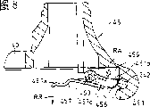
In addition, hub portion 232 thereunder have can vehicle seat column 3 is outstanding downwards the open end, in addition, electronic auxiliary unit 1 be positioned at this hub portion 232 extended line downwards the rear be configured.Therefore, vehicle seat column 3 open end that can cross hub portion 232 is outstanding downwards.Its length can extend.Its result, the height adjustment range that can strengthen vehicle seat are vehicle seat height adjustment surplus.
When not using vehicle, vehicle seat column 3 further can be fallen downwards by unclamping clamping component 233.Shown in the long and two-short dash line in the image pattern like that, the most following some position at vehicle seat 4, vehicle seat column 3 connects back framework 23 downwards, set the moving up and down stroke that its lower end extends to the anterior position of electronic auxiliary unit 1, wear in the lower end of vehicle seat column 3 and can run through the anti-steel rope through hole 72 of usurping steel rope 71.For example hang over front-wheel WF as shown like that more and go up with lock 73 and lock by the anti-steel rope 71 (or chain, hereinafter referred to as steel rope) of usurping that can pass this steel rope through hole 72, front-wheel WF its rotation in the anti-scope of usurping steel rope 71 extensions is limited.Like this, substantially, because the activity of vehicle is limited, other people impassabitity rotates bicycle and moves it.Therefore, antitheft can certainly the employing of vehicle body can be extracted the structure that separates from hub portion 232 with vehicle seat support column 3, and, can avoid vehicle seat column 3 to take out by other people.In addition, in the present embodiment before and after vehicle frame is divided into, owing to connect the vehicle seat column of preceding framework side front-wheel and back framework side, even when vehicle frame is cut apart, also can lock effectively.
Fig. 2 is the block diagram of seeing from the car body left front of back framework 23, and Fig. 3 is its birds-eye view.In two figure, back framework 23 is made of left half 23L and right half 23R, is provided with teat 25BL, 25BR, 27BL, the 27BR that can pass above-mentioned bolt 25,27.On fastening part 26, also forming the teat that supports locating dowel pin, but not shown in Fig. 2, Fig. 3.Between teat 25BL, the 25BR and the hanging portion 70b (also with reference to Fig. 4) that is disposing the upper end that is formed on above-mentioned electronic auxiliary unit 1 between 27BL, the 27BR with clipping be mounted with the left half 23L and the right half 23R of back framework 23 fixedly.
Forming above the framework 23 in the back and to be used to the seat 237L, the 237R that the seat 234,235,236 of battery box 16 are installed and are used to install rear brake 10.In addition, the front portion of the hub portion 232 that the above-mentioned vehicle seat column on the framework 23 of back is used is forming mount pad 238, and this mount pad 238 is used to install source switch, and this source switch is used for from battery auxiliary unit 1 etc. being moved in the electric current power supply.
Source switch with key K operation is installed on present 238.In battery box 16 supportings present 234,235,236, be housed between the left half 23L and right half 23R of back framework 23.
In addition, promptly with on the faying face of preceding framework 22 forming hub portion 28 at the front end of back framework 23 as the pin (not shown) of the hub portion 241 of the part of hinge 24 and free rotation ground supporting blocking device.In hub portion 241, insert pivot pin 242, packing ring 243 and back-up ring 244 are installed at its front end.The hook of preceding framework 22 sides of the part of formation hinge is sold 242 with this and is combined.
Fig. 4 be expression back framework 23 and battery box 16 and electronic auxiliary unit 1 the installation relation want portion's lateral plan.In Fig. 4, forming hanging portion 70a, the 70b that is used for electronic auxiliary unit 1 is connected on the framework 23 of back around the case body 70 of electronic auxiliary unit 1, on hanging portion 70a, 70b front end, form hub portion respectively, in this hub portion, wearing bolt 25,27 respectively.The 25BL of hub portion of this bolt 25,27 framework 23 after running through etc. are attached at hanging portion 70a, 70b on the framework 23 of back, and thus, electronic auxiliary unit 1 is suspended on the framework 23 of back.The case body 70 of electronic auxiliary unit 1 is preferably made by resin forming product for lightweight.
Like this, the fixed part of framework 23 after 1 pair of the electronic auxiliary unit and the left and right sides partitioning portion fixed portion each other of back framework 23 are located at a position with unifying, thus, can reduce number of parts, and can dwindle the space that these fixed parts and fixed portion are set, can seek dwindling in the size of the back framework 23 of this part.
The free-wheel clutch that does not show by figure on bent axle 11 is in conjunction with legpower input gear 30, and this legpower input gear 30 meshes with the miniature gears 31a of synthetic gear 31.In addition, engagement auxiliary power gear (boosting gear) 32 big gear wheel 32a on the miniature gears 29 of motor M, the miniature gears 32b that rotates integratedly with this big gear wheel 32a and the big gear wheel 31b of above-mentioned synthetic gear 31 mesh.In addition, output gear 34 engagements on the big gear wheel 31b of synthetic gear 31 and the axle that is fixed on drive sprocket 33.The case body 70 of preferably electronic auxiliary unit 1 and boosting gear 32 are made by being used for the weight-saving resin forming product, also can become helical wheel from the viewpoint of solemn silence etc.
The axletree 331 of supporting wheels WR is set in the rear end of back framework 23, on this axletree 331, passes through not shown free-wheel clutch in conjunction with driven sprocket 332.Between drive sprocket 33 and driven sprocket 332, open and establishing above-mentioned chain 15.
In Figure 14, symbol H represents the scope of the position of stretch-draw side 15T on short transverse of the chain 15 that the right side framework 23R in the framework 23 of back is interior.From Fig. 4 and Figure 14 as can be known, the stretch-draw side 15T of above-mentioned chain 15 is almost wholely being covered by this right side framework 23R in side-looking along it.Therefore, under the situation of the cover that chain 15 special uses are not set, chain 15 can be covered, the minimizing of part number can be realized.
Like this, the rotation of motor M is delivered to synthetic gear 31 by miniature gears 29 and boosting gear 32, and the legpower of importing from bent axle 11 passes through the legpower gear transmission to synthetic gear 31.Then, legpower and auxiliary power are delivered to drive sprocket 33 after making a concerted effort with synthetic gear 31, are being delivered to trailing wheel WR by driven sprocket 332.The rotation of the controller 37 of the front portion in the case 70 according to the legpower value control motor M of the force testing device input of not showing from figure is set.
Rear lower portion at body case 70 is installed with pivot 36, and these pivot 36 free rotation ground supportings the main support 35 that is made of the aluminum alloy formed products.In addition, be provided with above-mentioned shank (projection) 70c in the lower end of body case 70.This shank 70c framework 22 and back framework 23 when having separated before making are the projections that the trailing portion of the bicycle that comprises back framework 23 is supported oneself, and in the time of on being placed into ground, can erect on the ground voluntarily with this shank 70c and trailing wheel WR.
In the hub portion 28,28 of front end that is located at back framework 23, interting stop pin 39 with locking bar 38.With this stop pin 39 is that the center is provided with bolt 391 rotationally, and spiral is installed with nut 392 on this bolt 391.Bolt 391 is through in the groove of the outstanding joint portion 40 of in the past framework 22, and the one side of nut 392 contacts with this joint portion 40 and forms fixed.The hole off-centre of the relative hub of middle body portion 28 of the stop pin 39 of screw 391 is installed, rotates the butt intensity of regulating above-mentioned nut 392 and joint portion 40 by making locking bar 38.As shown in the figure, under the state that locking bar 38 is turned to the position that carries over back framework 23, nut 392 and joint portion 40 powerful contacts, preceding framework 22 and back framework 23 powerful combinations.Fixed the butt maximum of intensity with joint portion 40 of nut 392 can be by the amount of spin decision of nut 392.
In addition, by with securing rod 38 to rotating from the promptly vertical direction of the back direction left of framework 23 with car body, nut 392 corresponding to the offset of stop pin 39 to 40 directions of leaving (car body the place ahead) bias from the joint portion, fixed the dying down that nut 392 is produced.Its result rotates relative to stop pin 39 by making nut 392, can remove the combination of nut 392 and joint portion 40.Can be central folding prestack framework 22 and back framework 23 with hinge 24.
The front portion that is located at back framework 23 promptly is used to keep be installed with on the above-mentioned mount pad 238 (Fig. 2) of front side of hub portion 232 of vehicle seat column the source switch 50 by key K operation.
In battery box 16 supportings present 234,235,236, and be housed between the left half 23L and right half 23R of back framework 23.In battery box 16, accommodating battery 41.Battery 41 forms the assembly structure of accommodating the many battery pack 411 that for example are made of Ni-MH battery in case 412.Has the telltale 42 that shows electric surplus by light-emitting diode display on the top of case 412.In addition, employed charge connector 43 and wire fuse (not shown) also are located in the case 412 when charging in that battery 41 is taken out from battery box 16.On the protrusion 161 of the bottom of battery box 16, accommodating the terminal (not shown) that connects battery 41 and above-mentioned controller 37.
Be provided with on battery box 16 and cover 162, these lid 162 usefulness hinges 163 are installed on the battery box 16.Represented to open 162 the state that covers with the long and two-short dash line among the figure.Except being set, the window (figure does not show) that can see aforementioned display device 42 also is being provided with locking device 44 on the lid 162.This locking device 44 have by the turn key (with the key K of operating power switch can be shared) and the pawl 441 that can come in and go out, this pawl 441 combines with battery box 16 and locks.
Below describe the above-mentioned hinge 24 that connects above-mentioned preceding framework 22 and back framework 23 in detail.Fig. 6 is the top plan view of rearward end that comprises the preceding framework 22 of hinge 24, and Fig. 7 is its front elevation (figure that sees from the car body rear).This rearward end can be by constituting with welding and the incorporate rear end of the tubular member part (hereinafter referred to as end piece) that constitutes preceding framework 22.In two figure, on end piece 45, forming hook 451, this hook 451 is embedded in and is located at 241,241 in the above-mentioned hub portion of back on the framework 23, can combine with above-mentioned pivot pin 242, sets size and position so in this wise.
In order to stop up the opening portion (notch part) of the hook 451 that forms U word shape, be provided with lockplate 452.Lockplate 452 by pin 453 pivot suspensions on end piece 45.On end piece 45, be provided with control lever 455 by spring pin 454 pivot suspensions.Control lever 455 has the operating portion 455a and the hook portion 455b of finger press.Control lever 455 is connected with lockplate 452 by extension spring 456, and hook 455b combines with the frame of this breach window 452a from being formed on breach window 452a on the lockplate 452 in the face of i.e. back framework 23 sides of the table side of lockplate 452.Combine with lockplate 452 by this hook 455b, though extension spring 456 acting on,, lockplate 452 is limited to the rotation of arrow R direction.Control lever 455 has the contact part 455c with end piece 45 butts near above-mentioned pivot suspension part, quiescing bar 455 rotates to arrow RR direction from shown position.
Constitute according to this, owing to stopping up the peristome of hook 451 by the leading section of lockplate 452, so can not deviate from from hook 451 with hook 451 conjugate pivot pins 242.Therefore, even removed by above-mentioned securing rod 38 operating locking means, car body framework (being made of preceding framework and back framework) can only be that the center folds with pivot pin 242 also.
After having folded this vehicle frame,, the operating portion 455a of control lever 455 is pressed into to the depths of end piece 45 (arrow RF direction) for framework before being separated into again 22 and back framework 23.So control lever 455 is that rotate at the center with pin 454, lockplate 452 is that rotate at the center with pin 453, and the opening portion of hook 451 is opened wide.Therefore, pivot pin 242 can be deviate from from hook 451.Vehicle frame can fully separate at the connecting bridge of preceding framework 22 with back framework 23.
The result that control lever 455 and lockplate 452 are rotated, the hook 455b of control lever 455 and the combination of lockplate 452 are disengaged, and after the pushing that has stopped control lever 455, the opening-wide state of above-mentioned opening portion is also kept.Therefore, can use two hand stages the ground easily bulldozing operation of implementation and operation bar 455 and the detached job of car body framework respectively.
When more separated car spare being assembled into one, after making pivot pin 242 hang in the hook 451, lockplate 452 is pressed into hook 451 sides, make the hook 456b and lockplate 452 combinations of control lever 455.Stop up the opening portion of hook 451 by this operation.The faying face of framework 22 and back framework 23 is relative before then making, and the nut 392 of blocking device shown in Figure 4 is hung on the joint portion 40, makes securing rod 38 to the direction rotation along back framework 23, locks.The nut 392 when making securing rod 38 be positioned at position along back framework 23 and the tight ness rating of joint portion 40 can be by the position adjustments of the nut 392 of relative bolt 391.
Preceding framework 22 with above-mentioned end piece 45 is pipe structures of the hollow that is made of the aluminium extrusion material, and is when above-mentioned folding stand 2 like that, open ended.That is, preceding framework 22 is airtight when vehicle uses usually, and the people can not stretch into the operation of hand etc. from the outside, and when having folded vehicle frame 2, because an end opens wide, the people can get involved cylindrical container.
Therefore, can in the preceding framework 22 of the form of this cylindrical container, accommodate in motion the article that do not use, when stopping to travel, use.For example, when depositing the elec. vehicle bicycle, usually use car body is connected the anti-Steel wire rope lock (Steel wire rope lock) of usurping on the fixation construct of pillar etc.This Steel wire rope lock has degree of freedom in order to make the sample attitude of locking, use be long copper rope.But it is cumbersome carrying Steel wire rope lock when mobile, and the danger of losing in addition.In order to solve such problem, the hollow bulb of framework 22 before can utilizing.
Below, the variation of above-mentioned hinge 24 is described.Fig. 8 is the rearward end plane cross sectional drawing of preceding framework 22 of the variation of hinge 24, and Fig. 9 is its front elevation, the identical or equal part of expression of the symbol identical with Fig. 6, Fig. 7.In the drawings, the pivot pin 242 that is fixed on back framework 23 sides combines with hook 451, can not deviate from order to make this pivot pin 242, on the position of the opening portion (notch part) that stops up hook 451 lockplate 457 is set.Lockplate 457 has in order to draw operating portion 457a that hangs finger and form and the locking part 457b that stops up above-mentioned notch part, uses pin 453 pivot suspensions on end piece 45.In conjunction with spring (helical torsion spring) 458, this spring 458 is acting on the 457a of aforesaid operations portion near the direction of end piece 45, in other words with the power of above-mentioned locking part 457b to the direction of leaving from end piece 45 on lockplate 457.But, contact with the end face of end piece 45 because the rear end of locking part 457b is the end 452c of operating portion 457a side, the locking part 457b of lockplate 457 more than the position relative with above-mentioned notch part can not to from end piece 45 away from the direction rotation.
In addition, in order to make locking part 457b, on end piece 45, forming disengaging portion (recess) 459 to rotating with the approaching direction (arrow RA) of end piece 45.The degree of depth of this disengaging portion 459 is set at locking part 457b and flees from and size that the notch part of hook 451 is opened to end piece 45.
According to this structure, because lockplate 457 is suppressed by spring 458, the locked part 457b of the opening portion of hook 451 is stopping up, and therefore, pivot pin 242 can not be deviate from from hook 451.Therefore, use when stating securing rod 38 operating locking means only having removed, only to fold for middle heart with pivot pin 242.
For framework 22 and back framework 23 before this vehicle frame further is separated into after folding, draw the operating portion 457a that hangs over lockplate 457 to go up on finger and draw to the direction of leaving from end piece 45 (arrow RR direction).So locking part 457b keeps out of the way in the disengaging portion 459 and the opening portion of hook 451 is opened.Therefore, pivot pin 242 can be deviate from from hook 451, and vehicle frame can fully separate at the connecting bridge of preceding framework 22 with back framework 23.
When again the chassis mount that separates being one, by pivot pin 22 being pressed against on the locking part 457b and locking part 457b being kept out of the way in the 459b of disengaging portion.If pivot pin has been accommodated in the hook 451, then remove the thrust pressure of 242 couples of locking part 457b of pivot pin.Its result, by the elastic force of spring 453, locking part 457b stops up the opening portion of hook 451 to rotating with arrow RA opposition side.
In the embodiment of above-mentioned hinge 24, pivot pin 242 is located at back framework 23 sides, will be located at preceding framework 22 sides in conjunction with the hook 451 of this pivot pin 242 and the blocking device that constitutes by lockplate 452,457 and control lever 455 etc.But, also can with this on the contrary pivot pin 242 be located at preceding framework 22 sides, lockplate 452 grades are located at back framework 23 sides.
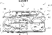
Figure 10 be the electrically assisted bicycle that carries four-wheel automobile (being set at lorry or RV car) at this want portion's birds-eye view, Figure 11 is the block diagram from seeing with vehicle front.In two figure, be provided with the pallet 58 that is used to take in electrically assisted bicycle along the fore-and-aft direction of automobile at the rear portion of automobile WGN with freely coming in and going out.Before framework 56 below that is fixed on the rear portion seat 57 in the automobile WGN be used to limit the boundary of the anterior position of the pallet 58 in the automobile WGN.The rear of upper framework 59 framework 56 before above-mentioned is fixed in the automobile on the WGN, shelf (not shown) preferably in upper support, the pallet 58 that is made of resin material is configured in the space that is impaled by above-mentioned preceding framework 56 and upper framework 59 with the guide rail guiding scheming not show and along automobile fore-and-aft direction free sliding ground.On upper framework 59, keeping the charger 60 of battery 41 in its left side.
Below the folding above-mentioned electrically assisted bicycle and the lift-launch of carrying in automobile are described in proper order.For electrically assisted bicycle is carried in automobile WGN, at first pallet 58 is pulled out to the car rear, above pallet 58, be provided with space freely, like this, the lid 162 of at first opening battery box 16 takes out battery 41 from electrically assisted bicycle, be accommodated in the preceding centre of pallet 58.Then, unclamp clamping element 233 vehicle seat column 3 is extracted from back framework 23, separate vehicle seat column 3 and vehicle seat 4 again.Vehicle seat 4 is accommodated in the laterally right-hand of battery 41, vehicle seat column 3 is accommodated in the right corner place of pallet 58.
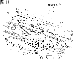
Then, separate vehicle frame.Before this separated, the turn-knob 61 of the above-mentioned joint 6 of operation was folding from joint 6 with handgrip column 7 earlier.Then, operational lock plate 38, the locking of the connecting portion of framework 22 and back framework 23 before removing and be that the center folds with pivot pin 242 with vehicle frame.Like this, pushing aforesaid operations bar 455 (examples of Fig. 6) or draw lockplate 457 (example of Fig. 8) and with pivot 242 in the past the hook 451 of framework 22 deviate from, separate vehicle frame.Before framework 22, handgrip column 7, handgrip 8, front fork 5, and front-wheel WF accommodated near the left side of pallet 58 integratedly.In addition, back framework 23, electronic auxiliary unit 1, and trailing wheel WR after having folded pedal 13 integratedly near pallet 58 right sides be accommodated in the pallet 58.
Figure 12 is the perspective rear view of automobile WGA, and Figure 13 is that this wants portion's section-drawing.As shown in figure 12, under the state of having pulled out pallet 58, electrically assisted bicycle is deviate to bicycle rear from the scope that it is almost all covered by shelf 65, and the user can easily not unloaded electrically assisted bicycle by shelf 65 with hindering from automobile.
In addition, on the inside side walls of automobile WGN, be provided with the socket 66 of AC100 volt.As shown in figure 13, the charger 60 in the inboard that is installed in shelf 65 passes through lead 67 from socket 66 supply powers, uses the direct current of the assigned voltage of charger 60 rectifications to supply with batteries 41 by lead 68 again.In addition, lead 68 is connected by adaptor union 43 with battery 41.
Like this, utilizing time before the destination that AC socket 66 for example can use effectively up to the excursion centre etc. to use by the engine-driven generator of automobile WG gives battery 41 chargings.
Figure 15 is the partial cutaway block diagram of expression battery structure.In the figure, battery 41 by the battery body of packing 410 parcel of shrinkable film (for example, arrange 20 Ni-MH battery groups) 411 and accommodate the resin forming product casing 412 that 2 of battery body 411 cuts apart and constitute, on casing 412, be provided with telltale 42, be used for electrically-charged adaptor union 43, insurance 44.This telltale 42 is by lighting the surplus of a plurality of LED with its quantitaes battery electricity of lighting.In addition, be used to carry and be installed in casing 412 free to rotately to the handle 46 of battery box 16 loading and unloading.Be provided with battery body 411 bonded assembly terminals 47,47 in the bottom of casing 412.
Figure 16 is the block diagram of outward appearance of expression battery box 16, and Figure 17 is a side cutaway view, and Figure 18 is that the A-A of Figure 17 is to view.In these figure, battery box 16 is by 234,235,236 supportings of above-mentioned seat, and its length direction is consistent with the car body fore-and-aft direction etc. is configured, and is housed between the left half 23L and right half 23R of back framework 23.Battery box 16 is made of case body 161 and lid 162, this case body 161 for from can loading and unloading battery 41 its tops open.This lid 162 covers this open upper part.Lid 162 usefulness hinges 163 are installed on the case body 161 freely to rotate, so that it can be opened to the side direction revolution of car body.The long and two-short dash line of Figure 15 has represented to open 162 the state that covers, by length direction and car body fore-and-aft direction are as one man disposed case body 161, compare with the situation that length direction is configured to approximate vertical, it is big that opening between the open upper part becomes, and therefore can easily carry out the charge and discharge operations of battery 41.
The lid 162 on except being provided with the window 48 that is used for see-through display 42, also be provided with locking device 54, this locking device 54 has the pawl 541 that can come in and go out by key (can be shared with the key of operating power switch), and this pawl 541 combines with the upper end of this case of case 161 and locks.
In case body 161, accommodating battery 41, forming terminal box 164 in the bottom of case body 161.In terminal box 164, accommodating the terminal 49,49 that combines with the terminal 47,47 of battery 41 sides.The cable that terminal 49,49 usefulness figure does not show is connected with above-mentioned controller 37.Be provided with on the top of case body 161 from being formed on the breach that covers on 162 the edge to the outstanding U-shaped member 46 in side.This U-shaped member 46 keeps the bearing piece of securing rod 38 to use as being used in the position along above-mentioned back framework 27.
The body rear place of leaning against of case body 161 is provided with battery 41 is remained on lock arm 51 in the battery box 16.Lock arm 51 can use pin 52 pivots to be bearing on the case body 161 to the car body fore-and-aft direction with fascinating.In the part that is provided with lock arm 51, case body 161 becomes two layers, is accommodating lock arm 51 among these two layers of walls.Lock arm 51 extends upward from pin 52, and its front end faces the inboard of case body 161 from the madial wall of two layers of wall part.Lock arm 51 its front ends that are projected into battery 41 sides are set position and the shape among the recess RS of the case 412 that can embed battery 41 for.
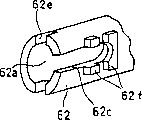
Be installed with or forming the sheet 53 that hangs down leaning on the edge at car body rear of lid 162.This sheet 53 that hangs down is being closed under 162 the state of covering, between the lateral wall of the back of the body of insertion lock arm 51 (by the face at car body rear) and above-mentioned two layers of wall, for to above-mentioned back of the body effect thrust pressure, under the state that lid 162 has been opened, be set at lock arm 51 can be to the position and the shape in the space that above-mentioned lateral wall direction is fascinated.When vehicle seat is in lower position and is locked in the position of representing with the dotted line of Fig. 1 under the unflagging state of steel rope, vehicle seat is in 162 the switching scope covered, vehicle seat can not move up owing to steel rope, therefore, if it is, more favourable to the locking of battery even having forgotten to carry out the loading and unloading of battery to covering when locking.Then, describe in detail handgrip column 7 is combined in joint 6 on the front fork 5.Figure 18 is the cross sectional drawing of overlooking of joint 6, and Figure 19 wants portion's block diagram.But be located at hole 62a and the hole 62b vertical that axle 63 levels that forming knob 61 on the fittings body 62 at top of front fork 5 connect with hole 62a.Hole 62a, 62b have rotating grooving 62c, 62d in the horizontal surface of axle 63 in joint 62.
The outside thread 63a that is formed on the front end of axle 63 screws among the negative thread 7a of the lower end that is formed on handgrip column 7.Forming 7b of lining portion and protuberance 7c in the lower end of handgrip column 7.The end face of this 7b of lining portion and fittings body 62 is chimeric, and this protuberance 7c combines with recess 61e on the end face that is formed on fittings body 62, the direction of regulation opposing tabs body 62.The chimeric above-mentioned lining 7b of portion that sets about column 7 around the terminal part of grooving 62c is forming the jut 62f that has in conjunction with the pod of protuberance 7c.In addition, on the car body rear side end of fittings body 62, be provided with retainer 55 by pin 64 free rotation ground supportings.
The folding operation of handgrip column 7 is described.Figure 20 is the block diagram of the joint 6 of expression folding step.Joint 6 when Figure 20 (a) expression electrically assisted bicycle uses.Under this state, handgrip column 7 erects to vertical direction.The lower end of handgrip column 7 and fittings body 62 are chimeric.For folding handgrip column 7, at first turning knob 61 unclamps fastening.
Then, shown in Figure 20 b, retainer 55 is opened for middle heart upward with pin 64, to car body the place ahead pushing knob 61.By opening retainer 55, as the figure that Figure 20 (c) expression is seen from knob 61 sides, producing big space between knob 61 and the fittings body 62, knob 61 can be to the displacement of car body the place ahead.By making knob 61 to the displacement of car body the place ahead, the protuberance 7c of handgrip column 7 throws off (with reference to Figure 20 (b)) from the recess 62e of fittings body 62.Its result, axle 63 can be in overlooking to anticlockwise direction (towards the left of car body direct of travel to) rotate.Figure 20 (d) is the figure that 90 ° state is rotated axle 63 in expression.
Then, shown in Figure 20 (e), handgrip column 7 is fallen shape to vertical lower, protuberance 7c is alignd with the pod of jut 62f.Last turning knob 61 and axle 63 spirals are inserted in the handgrip column 7 fix.
Figure 21 is the birds-eye view of pedal.Can be folding when not using at the pedal 13 that under the horizontally extending state of the left and right directions of car body, uses along crank 12.Pedal 13 has fixation side 131 that is installed in freely to rotate on the crank 12 and the movable side 133 that combines with fixation side 131 with pivot pin 132.Movable side 133 has the U type framework 132a by pivot pin 131 supportings, is provided with stop part 132b on this framework 132a with being free to slide.Stop part 132b is compressed that spring 132c suppresses and by to the pushing of the side of fixation side 131.On stop part 132b, engaging the operating portion 134 that is being provided with from the outside with connecting framework 132a.
When Foldable pedal 13, antagonism spring 132c makes operating portion 134 to car body outside displacement.So because the butt power of fixation side 131 and stop part 132b slows down, framework 132a can rotate for the center by pivot pin 131, can pedal 13 is folding along crank 12.
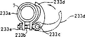
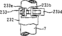
Figure 22 is the birds-eye view that vehicle seat column 3 is fixed on the clamping element 233 on the framework 23 of back.Figure 23 is a front elevation, and in two figure, clamping element 233 forms at an upper portion thereof as the part of the hub portion 232 on the joint portion 231 that is located at back framework 23.Clamping element 233 has ring 233a, bolt 233b and the clamping bar 233d of a part of incised notch that is located at circumference, this bolt 233b be located at the ring 233a notch part on, clamping bar 233d by pin 233c pivot suspension bolt 233b the head on.On ring 233a, welding and above-mentioned bolt 233b nut engaged 233e.
Clamping bar 233d constitutes pin 233c accentric cam relatively, corresponding to vehicle seat column 3 vertical surface in the rotational angle of clamping bar 233d, the power of clamping bar 233d clamping ring 233a changes.Center set is: in the position of representing with long and two-short dash line, gripping power is little, becomes big from this position with clamping bar 233d gripping power when the direction of arrow is rotated.Thus, the rotating operation by clamping bar 233d can carry out the clamp fitting of vehicle seat column 3 and clamp removing.In addition, vehicle seat column 3 can be suitably clamped by the rotation of above-mentioned clamping bar 233d and the amount that bolt 233b is screwed in nut 233e can be regulated in advance.
Below, the detailed construction of above-mentioned vehicle seat column 3 is described with reference to Figure 24 (a) and (b).Figure 24 (b) is that the A-A of Figure 24 (a) is to section-drawing.Body post 3 is made of tube body 300 and vehicle seat fixed part 301, the suitable position of the below of tube body 300 fixing the stopper section, for example the projection 302, above these projection 302 predetermined distances, representing minimum insertion line 303 with groove.
This projection 302 is that certain height can not be by bike when above in order to ensure the intensity of vehicle frame 2 at vehicle seat 4, the user is in order to increase vehicle seat 4, when upwards mentioning vehicle seat column 3 when unclamping clamping element 233, in scheduled mentioning in the boundary, this projection 302 combines with not shown stop carrier on the inside diameter that is formed on hub portion 232, and saddle tube 3 can not rise more than it again.At this moment, know that in order to make the user vehicle seat column 3 is minimum insertion positions, promptly show minimum insertion line 303 with the boundary of the upper end of hub portion 232 at the circumference of vehicle seat column 3.Therefore, when the user upwards mentions vehicle seat column 3, understand that easily vehicle seat column 3 come maximum upward extrusion position.
Inside diameter in hub portion 232, radially with above-mentioned stop carrier out-of-position position on, forming the groove that the projection 302 of above-mentioned vehicle seat column 3 can be passed through upward.Therefore, after the above-mentioned backstop carrier of this projection 302 and hub portion 232 combined, vehicle seat column 3 predetermined angular that sways when then mentioning upward, can be extracted separation fully from hub portion 232 with vehicle seat column 3.In addition, carrying out with above-mentioned when operating on the contrary, can be with both combinations easily.
To rear extension, rear brake steel rope 832 relies on the left half 23L of back framework 23 to the right half 23R of back, the variable-speed motor steel rope 831 edge vehicle frame 23 in the steel rope 83 partially from the way in the space that is impaled by back framework 23, and 23L rearward extends along this left half.
Below describe variable-speed motor steel rope 831 and the joint portion of variable-speed motor 85 and the joint portion of rear brake steel rope 832 and rear brake 10 in detail.Figure 26 is the right abaft block diagram of electrically assisted bicycle.In the figure, wearing through hole 86 on the right half 23R of back framework 23, variable-speed motor steel rope 831 passes this through hole 86 and is drawn out to the outside.Variable-speed motor 85 is located on the axletree 331 of trailing wheel WR.Fixing the adaptor union 87 on the end that is installed in variable-speed motor steel rope 831 on the housing 851 of this variable-speed motor 85.More particularly, variable-speed motor steel rope 831 is covered with by covering tube.Above-mentioned adaptor union 87 combines with this covering tube.And variable-speed motor steel rope 831 connects in the adaptor union 87 arrival housings 851 and with the portion of mechanism (not shown) of variable-speed motor 85 and combines.Seat 237L, 237R on be formed on back framework 23 (only representing seat 237R in Figure 26) head lamp brush guard pivot is supporting rear brake 10.
Figure 27 is the block diagram of seeing from the left back of electrically assisted bicycle, and Figure 28 is the block diagram of seeing from the below.In two figure, rear brake steel rope 832 rearward extends along the inboard of the left half 23L of back framework 23.In its way, rear brake steel rope 832 is kept by the connecting element 88 (Figure 28) that screw thread is fixed on the framework 23 of back.Wearing through hole 89 on the left half 23L of back framework 23, this through hole 89 of rear brake steel wire penetrating is pulled out upward.
Rear brake 10 has bar 101L, the 101R on seat 237L, the 237R (only representing a 237L among Figure 27,28) on be formed on back framework 23 of pivot suspension respectively.Rear brake steel rope 832 connects the lateral aperture on the front end (with the end of hinge portion opposition side) of the bar 101L that is formed on the left side, connect again the right side bar 101R front end and be drawn out to outside the car body right side.Rear brake steel rope 832 is fixed on the bar 101R on right side, and the bar 101L in left side is free to slide relatively.In more detail, rear brake steel rope 832 also similarly is covered with by covering tube with variable-speed motor steel rope 831, on the below lug boss 101LT of the bar 101L on the left of being fixed on.In the part, rear brake steel rope 832 is covered by flexual cover 90 between bar 101L, 101R leading section, and covers 90 spring members that contain the directive effect between the front end of oriented expanding bar 101L, 101R.Protrusion 101LB, 101RB below forming on bar 101L, the 101R, in-and-out bolt 92R, 92L among slotted hole 91L, the 91R of protrusion 101LB, 101RB below this are installed with brake block 93L, 93R respectively in the end of bolt 92R, 92L.For the wheel rim that makes brake shoe 93L, 93R and wheel WR is fit to, the position of bolt 92L, 92R is scalable in slotted hole 91L, 91R.
According to the structure of this rear brake 10, from handgrip 8 sides operation rear brake steel rope 832 time, dwindle between bar 101L, 101R front end.Its result, brake shoe 93L, 93R are pulled to the rim side of trailing wheel WR and brake.
Figure 29 is the block diagram of the left hand handle part of handgrip 8.In the figure, on the bar part 94 of handgrip 8, handle assembly 100 is installed, handle assembly 100 by transom 110, be used to make rear brake 10 actions brake-applying handle member 111, variable speed operation member 112, the abutment member 113 of variable-speed motor 85 actions are constituted, this transom 110 is connected Handleset 100 on the bar part 94 with freely loading and unloading.
In conjunction with variable-speed motor steel rope 831, this variable-speed motor steel rope 831 is imported into by the guide member 111b that perforation is located on the brake-applying handle member 111 on variable speed operation member 112.The Handleset 100 of above-mentioned structure, bar part 94 clamps or discharges relatively by the bar 110b that is operatively connected member 110, can carry out the loading and unloading of single job.
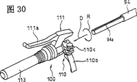
Figure 30 is the state of handle assembly 100 has been unloaded in expression from bar part 94 a block diagram.When unloading, raising wire 110b unclamps the clamping section 110c of transom, makes Handleset 110 rotate specified amounts to arrow R direction.Thus, the binding site in conjunction with the groove 94a of pin (not shown) and bar part 94 that is projected in the grip 110a can move to arrow D direction.Therefore, by bar assembly 100 being unloaded from bar part 94 to arrow D direction drawing from this state.Like this, in separate front and back during vehicle frame owing to easily handle assembly 100 is unloaded from handgrip 8, therefore, can be simply be one with containing in the segment set of the back framework 23 after the separation.
Figure 32 be the expression Steel wire rope lock the state of accommodating electrically assisted bicycle want portion's side isometric view.Figure 33 be before this bicycle of expression framework want portion's block diagram.In two figure, with the identical or equal part of expression of Fig. 1, Fig. 7, Fig. 8 same-sign.The Steel wire rope lock 17 of the hollow bulb of framework 22 is made of steel rope portion 18 and lock section 19 before being accommodated in, and has the key 20 that can cooperate on lock section 19.One end 18a of steel rope portion 18 is cemented on the lock section 19, and other end 18b can combine with the hole on being formed on lock section 19.The joint portion of this steel wire end 18b and lock section 19 can become by operation key 20 locks or unlocking condition.
As Figure 32, shown in Figure 34, Steel wire rope lock 17 is in curve 18c place warpage steel rope portion 18, and the opening that makes lock section 19 be positioned at preceding framework 22 is accommodated in preceding framework 22 distolaterally.As shown in the figure, because the hollow bulb linearity ground of preceding framework 22 is long, therefore, can under not little ground warpage or rolled-up situation, Steel wire rope lock 17 be taken in.Therefore, Steel wire rope lock is come in and gone out very light.Like this, owing to Steel wire rope lock 17 can be housed in the car body from the outside with can't see, the trouble that can save carrying also can prevent loss.
The effect of invention
As seen from the above description, according to the invention of claim 1 and claim 2, because electricity Concentrated area, dynamic auxiliary unit is configured in the rear of vehicle seat column, therefore, and front framework and its periphery Simple structure.
In addition, according to the invention of claim 3, can realize the lightweight of car body, and can Easily be formed on the rear framework will hang hub section that electronic auxiliary unit uses etc. According to right Require 4 invention, can effectively utilize the space between the frame section of the left and right sides.
In addition, according to the invention of claim 5, owing to can cover with the wide part of above-mentioned width The side of lid battery, therefore, can be so that outward appearance be good when having protected battery fully.
In addition, according to the invention of claim 6, owing to also can guarantee specially electronic auxiliary Help unit backward erecting device and the installing space of framework installation, therefore, can reduce number of components Amount and the size of dwindling rear framework.
In addition, according to the invention of claim 7, owing to do not need the cover of chain special use, therefore, Can reduce number of spare parts, not need to guarantee the space of having more than needed. In addition, according to Claim 8 Invention, can be certain in situation the about intensity of rear framework not being increased to more than required Bear the load that is added on the vehicle seat column.
According to the invention of claim 9~12, because locking device is combined with the vehicle seat column, Therefore, can be when preventing that car is stolen, it is such to prevent only taking out the vehicle seat column The mischief behavior. Particularly according to the invention of claim 10, be locked in car by making front vehicle wheel On the seat column vehicle can not be moved.
According to the invention of claim 13~16, can increase the accent of the short transverse of vehicle seat column Whole scope, be vehicle seat height adjustment amount. In addition, according to the invention of claim 14, by bike Time restriction vehicle seat column is applied to the power on the vehicle frame, can guarantee the intensity of this vehicle frame.
According to the invention of claim 15, can easily carry out vehicle seat column and vehicle seat hub section In conjunction with, separate. According to the invention of claim 16, the user can know easily that vehicle seat is vertical Post has arrived maximum overhang upward.
According to the invention of claim 17~19, the rear wheel brake steel wire rope is arranged to and does not hinder The form of the loading and unloading of battery. Particularly according to the invention of claim 19, can make outward appearance good.
In addition, according to the invention of claim 20~23, variable-speed motor is arranged as with steel wire rope might as well The form that hinders the loading and unloading of battery. Particularly according to claim 21 outward appearance is improved. In addition Outward, according to the invention of claim 23, can be with from two steel wire ropes that rearward extend That arranges is not numerous and diverse.
Claims (23)
1. electrically assisted bicycle, it is electrically assisted bicycle with manpower driving system and motor-driven system, this manpower driving system is used to transmit the legpower that is applied on the pedal, this motor-driven system can be according to above-mentioned legpower to the additional auxiliary power of above-mentioned manpower driving system, it is characterized in that, this bicycle comprises the vehicle frame that contains preceding framework and back framework, remain on the vehicle seat column on the above-mentioned after-frame, contain the electronic auxiliary unit of above-mentioned manpower driving system and motor-driven system, constitute above-mentioned back framework with left frame section and right frame section, and from above-mentioned electronic auxiliary unit being suspended on the framework of above-mentioned back at the rear portion near the above-mentioned vehicle seat column.
2. electrically assisted bicycle as claimed in claim 1 is characterized in that, above-mentioned left frame section and right frame section are mutually combining near place, car body the place ahead, and are forming the maintaining part of above-mentioned vehicle seat column in this joint portion.
3. electrically assisted bicycle as claimed in claim 1 or 2 is characterized in that, above-mentioned left frame section and right frame section are by aluminum dipping form casting system.
4. as any one the described electrically assisted bicycle in the claim 1~3, it is characterized in that between above-mentioned left frame section and right frame section, the equipped section of battery is arranged on above-mentioned vehicle seat column rear portion.
5. electrically assisted bicycle as claimed in claim 4 is characterized in that, the partial width of above-mentioned back framework next-door neighbour's vehicle seat column at its vehicle seat column rear in side-looking is wide.
6. electrically assisted bicycle as claimed in claim 1, it is characterized in that, have at the rear of above-mentioned electronic auxiliary unit hanging position and rear portion hookup mechanism that the place ahead of trailing wheel links above-mentioned left frame section and right frame section mutually, above-mentioned rear portion hookup mechanism double as is combined in device on the framework of above-mentioned back with above-mentioned electronic auxiliary unit.
7. electrically assisted bicycle as claimed in claim 1, it is characterized in that, have a chain on the driven sprocket of striding the drive sprocket that hangs on the output shaft that is located at above-mentioned electronic auxiliary unit and rear wheel-side, the length direction of the tight side of above-mentioned chain almost overall region is overlapping with above-mentioned right frame section in side-looking.
8. electrically assisted bicycle as claimed in claim 2, it is characterized in that, have and be located at preceding connecting connection parts below, above-mentioned joint portion, that interconnect the right frame section of above-mentioned left frame section and back, the same maintaining part cooperation of stating the vehicle seat column of connecting connection parts contacts with this vehicle seat column before above-mentioned, and having can 2 teat that support these vehicle seat columns.
9. electrically assisted bicycle as claimed in claim 1, it is characterized in that, comprise: be formed on the vehicle frame vehicle seat column maintaining part and at least the bottom set its moving up and down stroke and loading and unloading downwards highlightedly from vehicle frame and freely remain on vehicle seat column on the above-mentioned vehicle seat column maintaining part, its vehicle seat column has the joint portion that is used for for the locking device combination of this electrically assisted bicycle in its underpart.
10. electrically assisted bicycle as claimed in claim 9, it is characterized in that, above-mentioned joint portion is the through hole that is applied on the above-mentioned vehicle seat column, and above-mentioned locking device constitutes by the steel rope that passes above-mentioned through hole lodge front vehicle wheel when locking with in conjunction with the connecting portion at these steel rope two ends.
11. electrically assisted bicycle as claimed in claim 10 is characterized in that, above-mentioned vehicle frame may be partitioned into the preceding framework of supporting front-wheel and the back framework of supporting back vehicle seat column.
12. electrically assisted bicycle as claimed in claim 11 is characterized in that, is carrying battery in above-mentioned vehicle seat column rear lower portion, and, when the vehicle seat column is outstanding downwards, can not loading and unloading battery.
13. electrically assisted bicycle as claimed in claim 1, it is characterized in that, has the vehicle seat column of in hub portion, coming in and going out and can adjust height, this hub portion has the open end that this vehicle seat column can be given prominence to downwards, above-mentioned electronic auxiliary unit is positioned at the rear of the axis downwards of this hub portion, when above-mentioned vehicle seat column was maximum outstanding downwards, this vehicle seat column did not combine with above-mentioned electronic auxiliary unit.
14. electrically assisted bicycle as claimed in claim 13 is characterized in that, above-mentioned vehicle seat column has the stopper section that combines with above-mentioned hub portion when maximum outstanding upward.
15. electrically assisted bicycle as claimed in claim 14, it is characterized in that, above-mentioned stopper section is provided in a side of the protuberance of above-mentioned vehicle seat column bottom, and at the inside diameter of above-mentioned hub portion, the position of this protuberance has the slot part that this protuberance can pass through on the out-of-position position diametrically relatively.
16. electrically assisted bicycle as claimed in claim 15, it is characterized in that, on the periphery of above-mentioned vehicle seat column, be provided with the expression portion of the maximum extrusion position of expressing upward, in the position that above-mentioned stopper section combines with above-mentioned hub portion, the upper end position alignment of above-mentioned expression portion and above-mentioned vehicle seat hub portion.
17. electrically assisted bicycle as claimed in claim 1, it is characterized in that, comprise the trailing wheel that is configured in vehicle seat column rear, can be arranged on battery-mounting portion between vehicle seat column and the trailing wheel from the top free loading and unloading battery, be positioned at above-mentioned trailing wheel front portion rear wheel brake, make the drg steel rope of above-mentioned rear wheel brake action, above-mentioned drg steel rope rearward extends along vehicle frame from the operating portion that is located on the above-mentioned handgrip, and the bottom by battery-mounting portion is connected with rear wheel brake.
18. electrically assisted bicycle as claimed in claim 17, it is characterized in that, rear wheel brake is installed on the framework of back, and above-mentioned drg steel rope is in case extend to bending downwards behind the car body rear from above-mentioned trailing wheel system device, forwards extends via the bottom of above-mentioned battery-mounting portion.
19. electrically assisted bicycle as claimed in claim 18, it is characterized in that, be used in the wide left frame section of width on the above-below direction and rightly constitute frame and partly constitute the back framework, above-mentioned battery-mounting portion is configured between above-mentioned left frame section and the right frame section, and above-mentioned drg steel rope forwards extends along either party inboard of the wide framework of width in left frame section and the right frame section.
20. as claim 17 or 18 described electrically assisted bicycles, it is characterized in that, the variable-speed motor steel rope that has the variable-speed motor on the axle that is located at the above-mentioned trailing wheel of supporting and above-mentioned variable-speed motor is moved, above-mentioned variable-speed motor steel rope rearward extends along above-mentioned vehicle frame from the operating portion that is located on the handgrip, and the bottom by above-mentioned battery is being connected with above-mentioned rear wheel brake.
21., it is characterized in that above-mentioned variable-speed motor steel rope forwards extends along the inboard of the wide framework of width of the opposing party in left frame section and the right frame section as claim 17 or 18 described electrically assisted bicycles.
22. electrically assisted bicycle as claimed in claim 21 is characterized in that, has in the inboard in conjunction with the fixed parts of above-mentioned drg steel rope and above-mentioned variable-speed motor steel rope.
23., it is characterized in that the operating portion that is located on the above-mentioned handgrip is the assembly that above-mentioned rear wheel brake and variable-speed motor both sides' operating mechanism is consisted of one as claim 17 or 20 described electrically assisted bicycles.
Applications Claiming Priority (12)
| Application Number | Priority Date | Filing Date | Title |
|---|---|---|---|
| JP263902/2000 | 2000-08-31 | ||
| JP2000263902 | 2000-08-31 | ||
| JP317804/2000 | 2000-10-18 | ||
| JP2000317804A JP3874163B2 (en) | 2000-10-18 | 2000-10-18 | Electric assist bicycle |
| JP345741/2000 | 2000-11-13 | ||
| JP2000345741A JP4181294B2 (en) | 2000-08-31 | 2000-11-13 | Electric assist bicycle |
| JP2000350824 | 2000-11-17 | ||
| JP350824/2000 | 2000-11-17 | ||
| JP379922/2000 | 2000-12-14 | ||
| JP2000379922A JP3830127B2 (en) | 2000-12-14 | 2000-12-14 | Electric assist bicycle |
| JP104323/2001 | 2001-04-03 | ||
| JP2001104323A JP4530243B2 (en) | 2000-11-17 | 2001-04-03 | Electric assist bicycle |
Publications (2)
| Publication Number | Publication Date |
|---|---|
| CN1340435A CN1340435A (en) | 2002-03-20 |
| CN1205086C true CN1205086C (en) | 2005-06-08 |
Family
ID=27554834
Family Applications (1)
| Application Number | Title | Priority Date | Filing Date |
|---|---|---|---|
| CN01125582.XA Expired - Fee Related CN1205086C (en) | 2000-08-31 | 2001-08-16 | Electric-aided bicycle |
Country Status (5)
| Country | Link |
|---|---|
| EP (1) | EP1184278B1 (en) |
| CN (1) | CN1205086C (en) |
| AT (1) | ATE352481T1 (en) |
| DE (1) | DE60126210T8 (en) |
| ES (1) | ES2278666T3 (en) |
Families Citing this family (5)
| Publication number | Priority date | Publication date | Assignee | Title |
|---|---|---|---|---|
| JP5595228B2 (en) * | 2010-10-29 | 2014-09-24 | 本田技研工業株式会社 | Electric vehicle |
| JP6183089B2 (en) * | 2013-09-17 | 2017-08-23 | スズキ株式会社 | Electric vehicle |
| DE102014101757B4 (en) | 2014-02-12 | 2017-03-16 | Benteler Automobiltechnik Gmbh | Hollow profile component with flange |
| CN108163129B (en) * | 2018-01-30 | 2023-12-22 | 江苏理工学院 | Dual-purpose bicycle booster |
| CN108502061B (en) * | 2018-05-16 | 2024-01-30 | 浙江鼎立实业有限公司 | Multifunctional combined ignition switch for scooter, curved beam vehicle or battery car |
Family Cites Families (15)
| Publication number | Priority date | Publication date | Assignee | Title |
|---|---|---|---|---|
| DE2218730B2 (en) * | 1972-04-18 | 1975-05-15 | Solo Kleinmotoren Gmbh, 7032 Sindelfingen | Drive for motor cycle or moped - has battery powered electric motor and continuous gearing and freewheel final stage |
| US4410060A (en) * | 1981-11-16 | 1983-10-18 | Brown Group Recreational Products, Inc. | Power-assisted velocipede |
| JPH06239286A (en) | 1993-02-12 | 1994-08-30 | Yamaha Motor Co Ltd | Motor-driven bicycle |
| JPH09126917A (en) * | 1995-10-30 | 1997-05-16 | Yamaha Motor Co Ltd | Torque and speed detection device |
| JP3583845B2 (en) | 1995-11-25 | 2004-11-04 | 本田技研工業株式会社 | Vehicle locking device |
| JPH09301262A (en) * | 1996-05-16 | 1997-11-25 | Daido Steel Co Ltd | Motor assisted bicycle |
| JP3163046B2 (en) * | 1996-10-25 | 2001-05-08 | 三洋電機株式会社 | Man-powered vehicle with auxiliary power |
| JPH10138981A (en) * | 1996-11-11 | 1998-05-26 | Yamaha Motor Co Ltd | Assisted motor bicycle |
| JPH10152089A (en) * | 1996-11-22 | 1998-06-09 | Yamaha Motor Co Ltd | Coupler supporting device for motor-asisted hybrid bicycle |
| JPH10181651A (en) * | 1996-12-26 | 1998-07-07 | Yamaha Motor Co Ltd | Battery box fixing structure for motor-assisted bicycle |
| US5934401A (en) * | 1997-02-20 | 1999-08-10 | Currie Technologies, Incorporated | Precision direct drive mechanism for a power assist apparatus for a bicycle |
| JP4033527B2 (en) | 1997-09-30 | 2008-01-16 | 本田技研工業株式会社 | Battery storage device for battery-assisted bicycle |
| JP3808187B2 (en) * | 1997-09-30 | 2006-08-09 | 本田技研工業株式会社 | Electric assist bicycle |
| JPH11321748A (en) * | 1998-05-11 | 1999-11-24 | Miyata Ind Co Ltd | Mounting type battery charger for electric assist bicycle |
| JP2000108980A (en) * | 1998-09-30 | 2000-04-18 | Sanyo Electric Co Ltd | Motor assisted bicycle |
-
2001
- 2001-08-16 CN CN01125582.XA patent/CN1205086C/en not_active Expired - Fee Related
- 2001-08-30 ES ES01120878T patent/ES2278666T3/en not_active Expired - Lifetime
- 2001-08-30 EP EP01120878A patent/EP1184278B1/en not_active Expired - Lifetime
- 2001-08-30 AT AT01120878T patent/ATE352481T1/en not_active IP Right Cessation
- 2001-08-30 DE DE60126210T patent/DE60126210T8/en not_active Expired - Fee Related
Also Published As
| Publication number | Publication date |
|---|---|
| DE60126210T8 (en) | 2007-09-06 |
| EP1184278A3 (en) | 2004-11-24 |
| ATE352481T1 (en) | 2007-02-15 |
| EP1184278A2 (en) | 2002-03-06 |
| DE60126210T2 (en) | 2007-05-24 |
| ES2278666T3 (en) | 2007-08-16 |
| EP1184278B1 (en) | 2007-01-24 |
| DE60126210D1 (en) | 2007-03-15 |
| CN1340435A (en) | 2002-03-20 |
Similar Documents
| Publication | Publication Date | Title |
|---|---|---|
| CN1296248C (en) | Light motor cycle type vehicle | |
| CN1268507C (en) | Electric auxiliary bicycle and its accumulator holder and accumulator case | |
| CN1091054C (en) | Storage battery compartment of electrically-powered moped | |
| CN1310798C (en) | Folding bicycle | |
| CN1283514C (en) | Rear construction of vehicle | |
| CN1605534A (en) | Motorcycle | |
| CN1605530A (en) | Goods strorage structure for miniature motorcycle | |
| CN1158205C (en) | Improved bicycle dropout frame member | |
| CN1605539A (en) | Brake tongs braced structure of automatic bicycle | |
| CN1607140A (en) | Remote control apparatus for a scooter-type vehicle | |
| WO2020257479A1 (en) | Lightweight electric saddle type vehicle chassis | |
| CN1071662C (en) | Electrically-powered mopeol | |
| CN1205086C (en) | Electric-aided bicycle | |
| CN1177721C (en) | Article holding portion structure attached to cycle | |
| CN1282582C (en) | Moped | |
| CN1071663C (en) | Electrically-powered moped | |
| CN1308164C (en) | Loading cycle of two-wheel cycle and loading method for two-wheel cycle | |
| CN100344495C (en) | Motorcycle | |
| CN1288028C (en) | Steering handle rocker device for bicycle | |
| CN1288027C (en) | Bicycle | |
| CN1403332A (en) | Electric bicycle and its carring method | |
| CN1359823A (en) | Steering device for bicycle and steering device folding method | |
| JP2002087351A (en) | Battery storage device for power-assisted bicycle, and power-assisted bicycle | |
| CN1084690C (en) | Holding structure under seat of small two-wheeled motor cycle | |
| CN1282578C (en) | Fuel switch operating device of pedal type motor |
Legal Events
| Date | Code | Title | Description |
|---|---|---|---|
| C10 | Entry into substantive examination | ||
| SE01 | Entry into force of request for substantive examination | ||
| C06 | Publication | ||
| PB01 | Publication | ||
| C14 | Grant of patent or utility model | ||
| GR01 | Patent grant | ||
| C17 | Cessation of patent right | ||
| CF01 | Termination of patent right due to non-payment of annual fee |
Granted publication date: 20050608 Termination date: 20130816 |