CN1071663C - Electrically-powered moped - Google Patents
Electrically-powered moped Download PDFInfo
- Publication number
- CN1071663C CN1071663C CN98120837A CN98120837A CN1071663C CN 1071663 C CN1071663 C CN 1071663C CN 98120837 A CN98120837 A CN 98120837A CN 98120837 A CN98120837 A CN 98120837A CN 1071663 C CN1071663 C CN 1071663C
- Authority
- CN
- China
- Prior art keywords
- frame
- storage battery
- cover
- remaining amount
- button
- Prior art date
- Legal status (The legal status is an assumption and is not a legal conclusion. Google has not performed a legal analysis and makes no representation as to the accuracy of the status listed.)
- Expired - Fee Related
Links
Images


Classifications
-
- B—PERFORMING OPERATIONS; TRANSPORTING
- B62—LAND VEHICLES FOR TRAVELLING OTHERWISE THAN ON RAILS
- B62M—RIDER PROPULSION OF WHEELED VEHICLES OR SLEDGES; POWERED PROPULSION OF SLEDGES OR SINGLE-TRACK CYCLES; TRANSMISSIONS SPECIALLY ADAPTED FOR SUCH VEHICLES
- B62M6/00—Rider propulsion of wheeled vehicles with additional source of power, e.g. combustion engine or electric motor
- B62M6/40—Rider propelled cycles with auxiliary electric motor
- B62M6/55—Rider propelled cycles with auxiliary electric motor power-driven at crank shafts parts
-
- B—PERFORMING OPERATIONS; TRANSPORTING
- B62—LAND VEHICLES FOR TRAVELLING OTHERWISE THAN ON RAILS
- B62K—CYCLES; CYCLE FRAMES; CYCLE STEERING DEVICES; RIDER-OPERATED TERMINAL CONTROLS SPECIALLY ADAPTED FOR CYCLES; CYCLE AXLE SUSPENSIONS; CYCLE SIDE-CARS, FORECARS, OR THE LIKE
- B62K15/00—Collapsible or foldable cycles
- B62K15/006—Collapsible or foldable cycles the frame being foldable
Landscapes
- Engineering & Computer Science (AREA)
- Chemical & Material Sciences (AREA)
- Combustion & Propulsion (AREA)
- Mechanical Engineering (AREA)
- Transportation (AREA)
- Motorcycle And Bicycle Frame (AREA)
- Secondary Cells (AREA)
- Arrangement Or Mounting Of Propulsion Units For Vehicles (AREA)
- Valve Device For Special Equipments (AREA)
- Lubrication Of Internal Combustion Engines (AREA)
- Valve-Gear Or Valve Arrangements (AREA)
Abstract
一种电动助力自行车,具有辅助人力的电动机,车架可折叠;其中,在后车架3安装蓄电池装置32,该蓄电池装置32在上部具有显示蓄电池63残余量的残余量显示部64和使蓄电池残余量进行显示的显示按钮66,由罩35覆盖蓄电池箱上方,在该罩上安装用于透视残余量显示部的透视板76及用于按下显示按钮的操作按钮77。由此,可以防止行走中带下的泥水和尘土弄脏蓄电池箱,并可以容易地操作显示按钮。
An electric power-assisted bicycle has a motor that assists manpower, and the frame is foldable; wherein, a storage battery device 32 is installed on the rear frame 3, and the storage battery device 32 has a residual quantity display part 64 for displaying the residual quantity of the storage battery 63 on the upper part and a storage battery device The display button 66 for displaying the remaining amount is covered above the battery box by the cover 35, and a see-through plate 76 for seeing through the remaining amount display portion and an operation button 77 for pressing the display button are attached to the cover. This prevents the battery box from being soiled by muddy water and dust brought down during travel, and enables easy operation of the display buttons.
Description
本发明涉及具有辅助人力的电动机的电动助力自行车。The present invention relates to an electric power-assisted bicycle having an electric motor for assisting human power.
电动助力自行车是从电动机供给与蹬动踏板的力(踏力)相应的辅助动力的自行车,例如日本专利公报特开平9-2370号中的“电动助力自行车”就是这样的自行车。An electric power-assisted bicycle is a bicycle in which auxiliary power corresponding to pedaling force (pedaling force) is supplied from an electric motor. For example, the "electric power-assisted bicycle" in Japanese Patent Laid-Open No. Hei 9-2370 is such a bicycle.
根据该公报的图1及图2,该电动助力自行车的车架为由侧视V字状的前部车架3(编号引用了公报中记载的编号,以下同)和后部车架4构成的结合体。According to FIG. 1 and FIG. 2 of the publication, the frame of the electric power-assisted bicycle is composed of a V-shaped
前部车架3由主车架3A、中间部3B以及车座车架3C构成,该主车架3A从前管5向斜后方下降,该中间部3B连到主车架3A的下端并弯曲,该车座车架3C从中间部3B向斜后方上升。前部车架3的周围由车身罩16覆盖。The
主车架3A安装蓄电池箱组合体30及带主开关的锁定装置70,中间部3B安装电动机18,车座车架3C安装控制装置100。The main frame 3A is equipped with a battery box assembly 30 and a locking device 70 with a main switch, the middle part 3B is equipped with a motor 18 , and the seat frame 3C is equipped with a
另外,按照公报的图22,控制装置100在蓄电池电源BAT的电压为残量判定电压值以下的场合,使灯L亮灯,催促充电。In addition, according to FIG. 22 of the publication, when the voltage of the battery power supply BAT is equal to or lower than the residual capacity determination voltage value, the
上述灯L由于检修频率小,所以可直接安装在控制装置100上。然而,安装于车座车架3C的控制装置100易于被行走中跳起来的泥水和尘埃等弄脏。为了防止被弄脏,由车身罩16覆盖控制装置100,在将灯L安装在控制装置100上时,灯显示难以看到。为此,灯L的配置被限定于转向手柄7的周围。因而,限制了转向手柄7周围的设计自由度。The above-mentioned lamp L can be directly mounted on the
因此,本发明的目的就是要提高显示蓄电池残余量的残余量显示部的配置自由度。Therefore, it is an object of the present invention to improve the degree of freedom in arrangement of a remaining-amount display unit for displaying the remaining amount of a battery.
为了达到上述目的,本发明方案1提供一种电动助力自行车,该电动助力自行车具有可辅助人力的电动机,车架可以折叠,其特征在于:在车架上安装蓄电池箱,该蓄电池箱在上部具有显示蓄电池残余量的残余量显示部和用于使蓄电池残余量显示的显示按钮,用罩覆盖蓄电池箱的上方,在该罩安装用于透视残余量显示部的透视板和用于按下显示按钮的操作按钮。In order to achieve the above object, the present invention scheme 1 provides an electric power-assisted bicycle, the electric power-assisted bicycle has a motor that can assist manpower, and the vehicle frame can be folded, and is characterized in that a battery box is installed on the vehicle frame, and the battery box has a The remaining amount display part for displaying the remaining amount of the battery and the display button for displaying the remaining amount of the battery are covered with a cover above the battery box, and the see-through plate for seeing through the remaining amount display part and the display button for pressing the display button are installed on the cover. action button.
由于用罩覆盖蓄电池箱的上方,所以蓄电池箱在行走中不被溅起的泥水和尘埃等弄脏。而且,可以通过罩的透视板看到残余量显示部的显示内容。通过罩的操作按钮间接地按下显示按钮时,残余量显示部显示出蓄电池的残余量。这样,就不会将残余量显示部的配置限制在手柄周围。Since the top of the battery box is covered with the cover, the battery box will not be soiled by splashed muddy water, dust, etc. during travel. Furthermore, the display content of the remaining amount display part can be seen through the see-through panel of the cover. When the display button is pressed indirectly through the operation button of the cover, the remaining amount display part displays the remaining amount of the storage battery. In this way, the arrangement of the remaining amount display unit is not limited to the periphery of the handle.
本发明方案2的特征在于:操作按钮直接安装在透视板上。The feature of the second solution of the present invention is that the operation button is directly installed on the see-through plate.
操作按钮安装在透视板上,该透视板安装在罩上。The operation buttons are mounted on a see-through plate mounted on the cover.
下面结合附图说明本发明的实施形式The embodiment of the present invention is described below in conjunction with accompanying drawing
图1为本发明的电动助力自行车的侧视图。Fig. 1 is a side view of the electric power assist bicycle of the present invention.
图2为本发明的电动助力自行车的俯视图。Fig. 2 is a top view of the electric power assist bicycle of the present invention.
图3为本发明的车架的分解透视图。Fig. 3 is an exploded perspective view of the vehicle frame of the present invention.
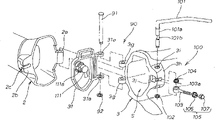
图4为本发明的后车架、车座支承车架以及动力机组周围的要部侧视图。Fig. 4 is a side view of main parts around the rear frame, the seat support frame and the power unit of the present invention.
图5为本发明的蓄电池装置的构成图。Fig. 5 is a configuration diagram of a storage battery device according to the present invention.
图6为将蓄电池装置收容于本发明后车架空间部的状态的侧剖视图。Fig. 6 is a side sectional view of a state in which a storage battery device is accommodated in the rear frame space of the present invention.
图7为示出本发明的残余量显示部、显示按钮以及罩的关系的要部放大剖视图。7 is an enlarged cross-sectional view of main parts showing the relationship between the remaining amount display unit, the display button, and the cover of the present invention.
图8为示出本发明的蓄电池装置与蓄电池导向件的关系的分解透视图。Fig. 8 is an exploded perspective view showing the relationship of the battery device and the battery guide of the present invention.
图9为图6的9-9剖视图。Fig. 9 is a sectional view taken along line 9-9 of Fig. 6 .
图10为本发明在车座支承车架上安装主开关及控制装置的状态的侧剖视图。Fig. 10 is a side sectional view of the state in which the main switch and the control device are installed on the supporting frame of the vehicle seat according to the present invention.
图11为图10的11-11剖视图。Fig. 11 is a sectional view taken along line 11-11 of Fig. 10 .
图12为图10的12-12剖视图。Fig. 12 is a sectional view taken along line 12-12 of Fig. 10 .
图13为本发明铰链机构及连接机构的分解透视图。Fig. 13 is an exploded perspective view of the hinge mechanism and connecting mechanism of the present invention.
图14为本发明的连接机构的侧视图。Fig. 14 is a side view of the connection mechanism of the present invention.
图15为本发明的铰链机构及连接机构的平面剖视图。Fig. 15 is a plane sectional view of the hinge mechanism and the connection mechanism of the present invention.
图16为本发明连接机构的作用图。Fig. 16 is an action diagram of the connection mechanism of the present invention.
图17为本发明铰链机构及连接机构的平面剖视图。Fig. 17 is a plane sectional view of the hinge mechanism and connecting mechanism of the present invention.
图18为本发明的前、后车架的折叠构造的作用图。Fig. 18 is an action diagram of the folding structure of the front and rear vehicle frames of the present invention.
图19为本发明的电动助力自行车的作用图。Fig. 19 is an action diagram of the electric power-assisted bicycle of the present invention.
图20为本发明的电动助力自行车的作用图。Fig. 20 is an action diagram of the electric power-assisted bicycle of the present invention.
“前”、“后”、“左”、“右”、“上”、“下”按照驾驶者看到的方向,Fr为前侧,Rr为后侧,L为左侧,R为右侧。另外,附图沿符号的方向观看。"Front", "Rear", "Left", "Right", "Up", and "Down" follow the directions seen by the driver, F r is the front side, R r is the rear side, L is the left side, and R is the Right. In addition, the drawings are viewed in the direction of the symbols.
图1为本发明的电动助力自行车的侧视图。Fig. 1 is a side view of the electric power assist bicycle of the present invention.
电动助力自行车1为折叠型自行车,在前后方向大体中央部可折叠地连接前车架2和后车架3,作为车架4。The electric assist bicycle 1 is a foldable bicycle, and a
前叉6可回转地安装在前车架2的前端部的前管5上,在该前叉6上安装着前轮7和手柄8。A
在后车架3周围的构造中,在后车架3的前端部安装向后上方延伸的车座支承车架11,在该车座支承车架11后端部的车座支柱安装部11a可上下进退地安装车座支柱13,在该车座支柱13的上端部安装鞍座14。在后车架3后端部安装后轮15,并在下端部安装动力机组16。In the structure around the
图中,符号8a为把手,符号8b为制动握把,符号12为车座支柱高度调节用柄,符号17为前制动器,符号18为后制动器,符号19为踏板,符号21为齿轮曲柄,符号22为曲柄轴,符号23为驱动链轮,符号24为从动链轮,符号25为空转轮,符号26为链条,符号27为停放支架。In the figure, the
图2为本发明的电动助力自行车的俯视图。为了易于理解,省略了图1中示出的车座支承车架11、车座支柱13以及鞍座14。Fig. 2 is a top view of the electric power assist bicycle of the present invention. For ease of understanding, the seat support frame 11 ,
在电动助力自行车车身中心C的右侧(一侧)配置折叠前车架2和后车架3时的铰链机构90、驱动链轮23、从动链轮24以及链26,在车身中心C左侧(另一侧)配置连接前车架2和后车架3的连接机构100。The
图3(a)~(d)为本发明的车架的分解透视图,(a)示出分解后的状态,(b)示出(a)的b-b剖面,(c)示出(a)的c-c剖面,(d)示出(a)的d-d剖面。Fig. 3 (a)~(d) is the exploded perspective view of vehicle frame of the present invention, (a) shows the state after disassembling, (b) shows the b-b section of (a), (c) shows (a) The c-c section of (d) shows the d-d section of (a).
如(b)所示,前车架2为椭圆形断面管。As shown in (b), the
如(a)、(c)、(d)所示,后车架3大体由环状的车架本体3a,从该车架本体3a的后部垂下的左右车架侧板3b、3b,连接该左右车架侧板3b、3b下端部间的底板3c,以及从车架本体3a后部和车架侧板3b、3b向后方延伸的左右后轮支承臂3d、3d构成。如(c)所示,由车架本体3a、左右的车架侧板3b、3b以及底板3c围成的空间部S成为蓄电池收容空间。空间部S的后部上方为如(d)所示那样地开放构成。车架本体3a在上部一体地形成前后2个安装凸台3e、3e,这些安装凸台3e、3e用于由螺栓固定车座支承车架11(参照图1)的下端部。As shown in (a), (c), and (d), the
为了轻量化,前、后车架2、3由铝合金等轻合金形成。例如,前车架2的前部2A由铝合金的挤压材形成,前车架2的后部2B由铝合金铸件构成,车架本体3a由铝合金铸件构成。In order to reduce weight, the front and rear vehicle frames 2 and 3 are formed of light alloys such as aluminum alloys. For example, the
然而,后车架3由盖31堵住前端。盖31的详细结构后述。However, the front end of the
图4为本发明的后车架、车座支承车架、以及动力机组周围的要部侧视图,以剖面示出动力机组16。FIG. 4 is a side view of main parts around the rear frame, the seat support frame, and the power unit of the present invention, showing the
在后车架3下部配置蓄电池装置32,在该蓄电池装置32的下位配置动力机组16,另一方面,在车座支承车架11上部配置主开关33,在该主开关33的下位配置控制装置34。The
详细地说,在后车架3的空间部S收容蓄电池32,在车座支承车架11上安装主开关33,同时在车座支承车架11的内部收容控制装置34。Specifically, a
后车架3的后部上方和车座支承车架11后面由罩35覆盖,其细节将在后面说明。另外,后车架3的背面及后端侧面由左右分割成两部分的后部罩36覆盖。The rear upper part of the
动力机组16以电动机41为驱动源,以辅助人力行走。详细地说,动力机组16由电动机41、安装在电动机41输出轴41a上的驱动齿轮42、啮合在驱动齿轮42的第1中间齿轮43、安装第1中央齿轮43的第1中间轴44、一体地设于第1中间轴44的第2中间齿轮45、啮合于第2中间齿轮45的第3中间齿轮46、通过单向离合器(图中未示出)连接于第3中间齿轮46的第2中间轴47、一体地设于第2中间轴47的第4中间齿轮48、啮合于第4中间齿轮48的从动齿轮49、接合从动齿轮49和上述驱动链轮23的回转筒体(图中未示出)、以及壳体51构成。The
动力机组16具有车速检测装置55。车速检测装置55由安装于电动机41输出轴41a上的磁性磁阻件(reluctor)56和电磁耦合线圈式传感器57构成。The
图5(a)~(d)为本发明的蓄电池装置的构成图,(a)示出将蓄电池装置32的一部分剖开的侧面,(b)示出蓄电池装置32的平面,(c)示出(a)的c-c剖面,(d)示出蓄电池32的背面。5 (a) to (d) are structural diagrams of the storage battery device of the present invention, (a) shows a partly cutaway side of the
蓄电池32的蓄电池箱61通过组合左右箱半体61L、61R并用小螺钉B1…(…表示多个,以下同)固定而构成,在该蓄电池箱61收容蓄电池63、残余量显示部64等,在背面安装2个外部端子65、65等。The
蓄电池箱61如图5(c)所示那样为在前后方向上细长的箱,在正视下呈下细的锥形,在前面一体地形成手把61a,在背面一体地形成外部端子用连接器61b,在上面开得有显示窗61c。在该显示窗61c如图佃)所示那样对着残余量显示部64的显示面64a和显示按钮66。The
残余量显示部64用于显示蓄电池63的残余量,具体地说,由排成1列的多个发光二极管64b…的亮灯,显示蓄电池63的电压。The remaining
显示按钮66为安装于残余量显示部64显示面64a的按钮,以便在残余量显示部64显示蓄电池63的残余量。通过按下该按钮,使图中未示出的开关接通,仅在规定的时间使残余量显示部64动作。由于仅在规定的时间内使残余量显示部64动作,所以可节电。The
图中,符号67为充电端子,符号61f为充电端子用开口。符号62g为后部下部锥面,设在充电端子67的上下相反侧。In the figure,
图6为本发明的在后车架空间部收容蓄电池装置的状态的侧剖视图,在形成后车架3空间部S的内壁3f的上部,用小螺钉固定罩35的后部,并用该罩35覆盖蓄电池箱61的上方。6 is a side sectional view of the state in which the storage battery device is accommodated in the rear frame space of the present invention. On the upper part of the inner wall 3f forming the space S of the
内壁3f由空间部S内的蓄电池导向部71和空间部S外的外部连接器72夹持。外部连接器72的接触销72a、72a与第1电线73(电线束)连接,并通过蓄电池导向件71内,与收容于空间部S的蓄电池装置32的外部端子65、65接触。The inner wall 3f is sandwiched between the battery guide 71 inside the space S and the
如上述那样,蓄电池装置32在后部下部具有后部下部锥面61g。因此,在将蓄电池装置32插入空间部S时,由于蓄电池装置32的后部下部不碰到后车架3的开口,所以易于插入。As mentioned above, the
图7为示出本发明的残余量显示部、显示按钮、及罩的关系的要部放大剖视图,由图可知,在罩35上安装着透视残余量显示部64的透视板76和用于按下显示按钮66的操作按钮77。7 is an enlarged cross-sectional view showing the relationship between the remaining amount display part, the display button, and the cover of the present invention. It can be seen from the figure that the see-through
具体地说,罩35以弹性配合的方式安装着对着残余量显示部64的显示面64a的透视板76,该透视板76由例如透明或半透明的树脂板或玻璃板构成。操作按钮77由橡胶材等弹性材料构成,以弹性配合的方式直接安装于透视板76,可通过套筒78按压显示按钮66的上面。Specifically, the
图8为示出本发明的蓄电池装置与蓄电池导向件的关系的分解透视图。Fig. 8 is an exploded perspective view showing the relationship of the battery device and the battery guide of the present invention.
该蓄电池导向件71是将锥形导向凸部71a、71a和肩导向凸部71b、71b形成一体而成,该锥形导向凸部71a、71a用于引导蓄电池箱61的下部锥形面61d、61d,该肩导向凸部71b、71b用于引导蓄电池箱61的肩部61e、61e。The battery guide 71 is formed by integrating tapered
因此,蓄电池导向件71由锥形导向凸部71a、71a及肩导向凸部71b、71b引导插入空间部S(参照图6)的蓄电池箱61的下部锥形面61d和肩部61e,在空间部S定位于规定的位置。在由蓄电池导向件71定位后的状态下,蓄电池箱61的外部端子用连接器61b配合于蓄电池导向件71的贯通孔71c中。因此,如图6所示,仅需将蓄电池装置32插入到空间部S,即可使外部端子65、65自动地与外部连接器72对齐位置,使接触销72a、72a接触。Therefore, the battery guide 71 guides the lower tapered surface 61d and the shoulder 61e of the
图9为图6的9-9剖视图。为了易于理解,省去了图6中示出的后车架3的内壁3f、罩35、以及蓄电池导向件71。Fig. 9 is a sectional view taken along line 9-9 of Fig. 6 . For ease of understanding, the inner wall 3 f of the
由该图可知,在空间部S收容完了状态下的蓄电池装置32由锥形导向件凸起部71a、71a定位。As can be seen from this figure, the
蓄电池箱61与底板3c之间形成间隙α。因此,蓄电池箱61的下面与底板3c不产生干涉,不摩擦。A gap α is formed between the
图10为在本发明的车座支承车架安装主开关及控制装置的状态的侧剖视图,示出安装构造的细节。Fig. 10 is a side sectional view of a state where a main switch and a control device are mounted on the seat support frame of the present invention, showing details of the mounting structure.
主开关33的具体安装构造,是在车座支承车架11的前面上部以弹性接合和小螺钉B2固定开关安装板81,在开关安装板81上安装主开关33。主开关33为钥匙开关,将点划线示出的钥匙82插入钥匙孔中进行回转操作,用于启动或关闭控制装置34的动作。The specific installation structure of main switch 33 is to fix switch mounting plate 81 with elastic engagement and small screw B2 on the front top of vehicle seat supporting vehicle frame 11, and main switch 33 is installed on switch mounting plate 81. The main switch 33 is a key switch, and the key 82 shown by the dot-dash line is inserted into the key hole for turning operation, which is used to start or close the action of the
另一方面,在控制装置34的具体安装构造中,将接合板86安装在车座支承车架11的上部,在该接合板86的孔86a挂住控制装置34一端的钩搭凸缘34a,用螺栓B3将控制装置34另一端的撑条34b安装在车座支承车架11的上部。控制装置34进行控制以使电动机41(参照图4)产生相应于蹬动踏板19(参照图1)的力的辅助动力。On the other hand, in the specific installation structure of the
主开关33和控制装置34之间由第2电线87(电线束)连接,另外,控制装置34与上述图6的蓄电池装置32之间由第1电线73连接。The main switch 33 and the
蓄电池装置32、主开关33、以及控制装置34处于邻接位置,因此,第1、第2电线73、87极短。The
图11为图10的11-11剖视图,在图中,用螺栓B4、B4将车座支承车架11的下端部安装在后车架3的安装支柱3e上。Fig. 11 is a sectional view taken along line 11-11 of Fig. 10. In the figure, the lower end of the seat support frame 11 is installed on the mounting
图12为图10的12-12剖视图,示出在车座支承车架11的接合板86的孔86a挂上控制装置34的钩挂凸缘34a的状态。FIG. 12 is a cross-sectional view taken along line 12-12 of FIG. 10 , showing a state in which the hooking
图13为本发明的铰链机构及连接机构的分解透视图。Fig. 13 is an exploded perspective view of the hinge mechanism and connecting mechanism of the present invention.
铰链机构90由形成于前车架2后端右侧部的铰链撑条2a、形成于后车架3前端右侧部的铰链撑条3g、形成于盖31的铰链撑条31a、插入到这些铰链撑条2a、3g、31a各孔中的带凸缘的铰链销91、以及固定于带凸缘铰链销91下端部的开口环92构成。The
连接机构100由以下部分构成:形成于后车架3前端左侧部的凸台部3h,形成于凸台部3h的上下贯通孔3i以及从上下贯通孔3i的中段向前方切开的切口槽3j,贯通该上下贯通孔3i的侧视为倒L字形的锁定用柄101,固定于锁定用柄101下端部的开口环102,在上述切口槽3j中配合于锁定用柄101的带配合孔螺栓103及扭簧104,拧入到带配合孔螺栓103的双螺母105(螺母106及盖形螺母107),形成于前车架2后端左侧部的凸缘2b,以及形成于凸缘2b的螺栓钩挂槽2c。The connecting
图14为本发明的连接机构的侧视图,将连接状态的连接机构100的要部形成剖面地示出。FIG. 14 is a side view of the connection mechanism of the present invention, showing the main parts of the
锁定用柄101在插入上下贯通孔3i的轴部101a的中段形成偏心凸轮部101b,在该凸轮部101b配合带配合孔螺栓103的配合孔103a。带配合孔螺栓103插入到螺栓钩挂槽2c中,并将拧入前端的双螺母105挂到凸缘2b上,从而连接前车架2和后车架3。In the
双螺母105拧入带配合孔螺栓103的深度为对于连接前车架2和后车架3适当的尺寸,预先加以设定。The depth that
图15为本发明的铰链机构及连接机构的平面剖视图,在图中,将用点划线示出的蓄电池装置32收容于后车架3的空间部S,关闭盖31,锁定钥匙柱体(锁定装置)111,进而连接该连接机构100。Fig. 15 is a plane sectional view of the hinge mechanism and the connection mechanism of the present invention. In the figure, the
安装于盖31的钥匙柱体111,通过在钥匙孔中插入图中未示出的钥匙并进行转动操作,使锁销111a锁到后车架3内的凸部3k。由于具有钥匙柱体111,所以可起到防止蓄电池装置32被偷盗的作用。The
连接机构100的扭簧104在使带配合孔螺栓103对时常挂在前车架2的凸缘2b的方向上施加弹力。因此,前车架2与后车架3可以时常维持稳定的连接状态。The
前车架2的后端开放,可在内部收容钢丝锁112。The rear end of the
钢丝锁112是为了防盗而挂在前轮7或后轮15的锁构件,通过环状钢丝112a和拨号式锁112b组合而成。在前车架2内插入钢丝112a时,钢丝112a由自身的恢复力压紧在前车架2的内面,所以不会掉出来。这样,可以有效利用前车架2的内部空间。The
图16(a)、(b)为本发明的连接机构的作用图,(a)示出连接前的状态,(b)示出连接后的状态。Fig. 16(a), (b) is the operation diagram of the connection mechanism of the present invention, (a) shows the state before connection, and (b) shows the state after connection.
在(a)中,使前车架2的后端与后车架3的前端对齐,将带配合孔螺栓103插入到螺栓钩挂槽2c中。此时,锁定用柄101如点划线示出的那样处于立起状态。因此,凸轮部101b处于从轴部101a的中心X向前车架2一侧偏心尺寸δ1的状态。另一方面,凸缘2b的背面与双螺母105之间的间隙为δ2。In (a), the rear end of the
从该状态,使锁定用柄101向空白箭头A的方向倒转回去时,凸轮部101b也向相同方向回转。由回转的凸轮部101b使带配合孔螺栓103张紧,向空白箭头B的方向移动。From this state, when the lock handle 101 is turned back in the direction of the white arrow A, the
如(b)所示,当使锁定用柄101变到点划线所示的例F位置时,凸轮部101b成为从轴部101a的中心X向与前车架2相反一侧偏心尺寸δ3的状态。由于用凸轮部101b使带配合孔螺栓103张紧,所以凸缘2b的背面与双螺母105之间没有间隙。这样,带配合孔螺栓103通过双螺母105将凸缘2b向后车架3的前端拉,将前车架2的后端与后车架3的前端连接。As shown in (b), when the locking
图17为本发明的铰链机构及连接机构的平面剖视图,示出的除连接机构、使前车架2倒下的状态。在该状态下,用钥匙113打开钥匙柱体111,即可打开盖31,更换用点划线示出的蓄电池装置32。Fig. 17 is a planar cross-sectional view of the hinge mechanism and the connecting mechanism of the present invention, showing a state in which the
图18为本发明的前、后车架的折叠构造的作用图。Fig. 18 is an action diagram of the folding structure of the front and rear vehicle frames of the present invention.
收容蓄电池32、连接前车架2和后车架3时,按以下作业顺序进行。When accommodating the
首先,在后车架3的空间部S插入蓄电池装置32(箭头①),关上盖31,锁定钥匙柱体111(箭头②),根据需要在前车架2内部收容钢丝锁112(箭头③),对齐前车架2的后端和后车架3的前端(箭头④),将带配合孔螺栓103插入凸缘2b的螺栓钩挂槽2c中(箭头⑤),倒下锁定用柄101,将带配合孔螺栓103挂在凸缘2b(箭头⑥),连接前车架2的后端和后车架3的前端。First, insert the
取出蓄电池装置时按与上述作业顺序相反的顺序进行。When taking out the battery unit, carry out the reverse order of the above operation sequence.
图19为本发明的电动助力自行车的作用图,示出从侧面看到的折叠状态的电动助力自行车1的构造。Fig. 19 is an action diagram of the electric power assist bicycle of the present invention, showing the structure of the electric power assist bicycle 1 in a folded state viewed from the side.
通过解除连接机构100,将前车架2折叠到右侧(图里面方向),电动助力自行车1大体成为一半的长度。该状态下的电动助力自行车1可由后轮15和停放支架27站立。也可以如图所示那样降低鞍座14。By releasing the
图20为本发明的电动助力自行车的作用图,示出折叠状态的电动助力自行车1的俯视构造。为了易于理解,省去了图19中示出的车座支承车架11、车座支柱13以及鞍座14。Fig. 20 is an action diagram of the electric power assist bicycle of the present invention, showing the plan view structure of the electric power assist bicycle 1 in a folded state. For ease of understanding, the seat support frame 11 ,
由于在车身中心右侧(一侧)集中配置驱动链轮23、从动链轮24、链26以及铰链机构90,所以,在折叠电动助力自行车的人站在车身左侧(另一侧)进行折叠作业时,链26等不形成障碍,因此作业性良好。另外,由于可由折叠后的前车架2、前叉5、前轮7来引导链26,所以不需要用于该状态下的链导向件的部件。Since the driving
本发明可由以上构成发挥如下效果。The present invention can exhibit the following effects with the above constitution.
本发明方案1由于用罩覆盖安装于车架上的蓄电池箱上方,所以蓄电池箱不会被行走中带下的泥水或尘埃等弄脏。The present invention's scheme 1 owing to cover the battery box top that is installed on the vehicle frame with cover, so battery box can not be made dirty by the muddy water or dust etc. that are brought down in walking.
由于在罩上安装透视残余量显示部的透视板,所以可通过透视板观看残余量显示部的显示内容。因此,即使用罩覆盖具有残余量显示部的蓄电池箱的上方,也可以容易地看到显示内容。Since the see-through plate that sees through the remaining amount display portion is installed on the cover, the display content of the remaining amount display portion can be viewed through the see-through plate. Therefore, even if the upper part of the battery box having the remaining amount display part is covered with a cover, the displayed contents can be easily seen.
由于在罩上安装了用于按下显示按钮的操作按钮,所以通过操作按钮间接地按下显示按钮,就可以在残余量显示部显示蓄电池的残余量。因此,即使用罩覆盖具有显示按钮的蓄电池箱的上方,也可以容易地操作显示按钮。Since the operation button for pressing the display button is mounted on the cover, the remaining amount of the storage battery can be displayed on the remaining amount display part by indirectly pressing the display button through the operation button. Therefore, even if the upper side of the battery box having the display button is covered with the cover, the display button can be easily operated.
这样,残余量显示器的配置不被限制在转向手柄周围,在提高转向手柄周围设计的自由度的同时,可提高残余量显示部配置的自由度。而且,残余量显示部的布线也可变短。In this way, the arrangement of the remaining amount indicator is not limited to the periphery of the steering handle, and the degree of freedom in the arrangement of the remaining amount display portion can be increased while increasing the degree of freedom in the design of the periphery of the steering handle. Furthermore, the wiring of the remaining amount display unit can also be shortened.
本发明方案2由于直接将操作按钮安装在透视板上,所以在将操作按钮安装在透视板上后,只要将透视板安装在罩上即可。由于将操作按钮部分地组装到透视板,所以可提高组装作业性,减少组装工时。
Claims (2)
Applications Claiming Priority (3)
| Application Number | Priority Date | Filing Date | Title |
|---|---|---|---|
| JP265971/1997 | 1997-09-30 | ||
| JP26597197A JP4108159B2 (en) | 1997-09-30 | 1997-09-30 | Electric assist bicycle |
| JP265971/97 | 1997-09-30 |
Publications (2)
| Publication Number | Publication Date |
|---|---|
| CN1212936A CN1212936A (en) | 1999-04-07 |
| CN1071663C true CN1071663C (en) | 2001-09-26 |
Family
ID=17424593
Family Applications (1)
| Application Number | Title | Priority Date | Filing Date |
|---|---|---|---|
| CN98120837A Expired - Fee Related CN1071663C (en) | 1997-09-30 | 1998-09-29 | Electrically-powered moped |
Country Status (4)
| Country | Link |
|---|---|
| JP (1) | JP4108159B2 (en) |
| CN (1) | CN1071663C (en) |
| FR (1) | FR2768990B1 (en) |
| IT (1) | IT1304997B1 (en) |
Cited By (1)
| Publication number | Priority date | Publication date | Assignee | Title |
|---|---|---|---|---|
| CN104411576B (en) * | 2012-06-29 | 2017-03-08 | 松下知识产权经营株式会社 | Battery mounting device and electric bicycle |
Families Citing this family (14)
| Publication number | Priority date | Publication date | Assignee | Title |
|---|---|---|---|---|
| JP4492905B2 (en) * | 2001-03-19 | 2010-06-30 | 本田技研工業株式会社 | Electric assist bicycle |
| NL1018948C2 (en) † | 2001-09-13 | 2003-03-20 | Sparta B V | Bicycle with auxiliary drive. |
| JP2003194194A (en) | 2001-12-28 | 2003-07-09 | Sunstar Eng Inc | Gear box and motor-assisted bicycle using the same |
| TW568050U (en) * | 2003-03-04 | 2003-12-21 | Takara Co Ltd | Electric bicycle |
| WO2004103762A2 (en) * | 2003-05-14 | 2004-12-02 | Taylor Loren T | Foldable child riding vehicle |
| ITMI20071352A1 (en) * | 2007-07-06 | 2009-01-07 | Campagnolo Srl | INSTRUMENTATION KIT OF A BICYCLE AND BICYCLE INCLUDING SUCH A KIT |
| CN101670774B (en) * | 2009-06-25 | 2012-06-13 | 好孩子儿童用品有限公司 | Battery installation structure and electric bicycle |
| JP2011025766A (en) * | 2009-07-22 | 2011-02-10 | Sanyo Electric Co Ltd | Folding type power-assisted bicycle |
| JP5460545B2 (en) * | 2010-09-30 | 2014-04-02 | 本田技研工業株式会社 | Battery module mounting structure for electric motorcycles |
| KR101201057B1 (en) | 2010-11-17 | 2012-11-14 | 삼성에스디아이 주식회사 | Waterproof battery pack |
| CN104029771A (en) * | 2013-03-07 | 2014-09-10 | 苏州小蜻蜓电动车有限公司 | Variable-speed folding bicycle |
| CN108502067A (en) * | 2018-06-07 | 2018-09-07 | 李锡如 | A kind of pipeline interior cabling structure and its application on three folding bicycles |
| CN111038636B (en) * | 2018-10-15 | 2020-12-18 | 程宝贤 | Bicycle folding structure and bicycle folding method |
| CN115416793A (en) * | 2022-09-15 | 2022-12-02 | 天津市金轮信德车业有限公司 | Shock attenuation formula electric bicycle |
Citations (1)
| Publication number | Priority date | Publication date | Assignee | Title |
|---|---|---|---|---|
| US4637274A (en) * | 1984-03-14 | 1987-01-20 | Kibbutz Gordonia Hulda | Auxiliary drive for pedal-driven road vehicles |
Family Cites Families (2)
| Publication number | Priority date | Publication date | Assignee | Title |
|---|---|---|---|---|
| JP3528996B2 (en) | 1995-04-17 | 2004-05-24 | 本田技研工業株式会社 | Electric assist bicycle |
| JP3645976B2 (en) * | 1996-07-08 | 2005-05-11 | 本田技研工業株式会社 | Battery mounting structure for battery-assisted bicycles |
-
1997
- 1997-09-30 JP JP26597197A patent/JP4108159B2/en not_active Expired - Fee Related
-
1998
- 1998-09-17 IT ITTO980790 patent/IT1304997B1/en active
- 1998-09-29 CN CN98120837A patent/CN1071663C/en not_active Expired - Fee Related
- 1998-09-29 FR FR9812148A patent/FR2768990B1/en not_active Expired - Fee Related
Patent Citations (1)
| Publication number | Priority date | Publication date | Assignee | Title |
|---|---|---|---|---|
| US4637274A (en) * | 1984-03-14 | 1987-01-20 | Kibbutz Gordonia Hulda | Auxiliary drive for pedal-driven road vehicles |
Cited By (1)
| Publication number | Priority date | Publication date | Assignee | Title |
|---|---|---|---|---|
| CN104411576B (en) * | 2012-06-29 | 2017-03-08 | 松下知识产权经营株式会社 | Battery mounting device and electric bicycle |
Also Published As
| Publication number | Publication date |
|---|---|
| IT1304997B1 (en) | 2001-04-05 |
| ITTO980790A1 (en) | 2000-03-17 |
| CN1212936A (en) | 1999-04-07 |
| JP4108159B2 (en) | 2008-06-25 |
| JPH1199974A (en) | 1999-04-13 |
| FR2768990A1 (en) | 1999-04-02 |
| FR2768990B1 (en) | 2002-01-11 |
Similar Documents
| Publication | Publication Date | Title |
|---|---|---|
| CN1071663C (en) | Electrically-powered moped | |
| CN1071662C (en) | Electrically-powered mopeol | |
| CN1091054C (en) | Storage battery compartment of electrically-powered moped | |
| CN1086348C (en) | Electrically assisted bicycle | |
| CN1191959C (en) | Motor assisted bike and power device | |
| JP5564619B2 (en) | Electric bicycle electrical component arrangement structure | |
| CN102730142B (en) | Motor-assisted bicycle | |
| CN1268507C (en) | Electric auxiliary bicycle and its accumulator holder and accumulator case | |
| JPH07329858A (en) | Battery attachment / detachment structure for electric assisted bicycles | |
| CN1091304C (en) | Cell charge-discharge structure for electric auxiliary bicycle | |
| CN1075992C (en) | Plate structure for shelterring body of electric asisting driven bicycle | |
| CN1101764C (en) | Battery placing structure of electric auxiliary bicycle | |
| CN1282582C (en) | Moped | |
| CN1756688A (en) | Saddle type vehicle | |
| CN1269685C (en) | Battery residual electric quantity meter of motor assisted bicycle | |
| JP3137316B2 (en) | Bicycle with electric auxiliary power | |
| CN1150104C (en) | electric booster | |
| JP3867836B2 (en) | Electric assist bicycle | |
| JP2003182668A (en) | Electric assist bicycle | |
| JP3832705B2 (en) | Electric auxiliary unit | |
| CN1340436A (en) | Bicycle | |
| JP2001106164A (en) | Electric auxiliary unit | |
| EP1092623B1 (en) | Motor-assisted bicycle | |
| CN1293140A (en) | Electri auxiliary parts | |
| CN1170264A (en) | Batteries for Electric Assisted Bicycles |
Legal Events
| Date | Code | Title | Description |
|---|---|---|---|
| C10 | Entry into substantive examination | ||
| SE01 | Entry into force of request for substantive examination | ||
| C06 | Publication | ||
| PB01 | Publication | ||
| C14 | Grant of patent or utility model | ||
| GR01 | Patent grant | ||
| C19 | Lapse of patent right due to non-payment of the annual fee | ||
| CF01 | Termination of patent right due to non-payment of annual fee |