CN1201410A - Volatile materials treatment system - Google Patents
Volatile materials treatment system Download PDFInfo
- Publication number
- CN1201410A CN1201410A CN96198130A CN96198130A CN1201410A CN 1201410 A CN1201410 A CN 1201410A CN 96198130 A CN96198130 A CN 96198130A CN 96198130 A CN96198130 A CN 96198130A CN 1201410 A CN1201410 A CN 1201410A
- Authority
- CN
- China
- Prior art keywords
- still
- distillates
- filter
- gas
- high temperature
- Prior art date
- Legal status (The legal status is an assumption and is not a legal conclusion. Google has not performed a legal analysis and makes no representation as to the accuracy of the status listed.)
- Pending
Links
Images


Classifications
-
- B—PERFORMING OPERATIONS; TRANSPORTING
- B01—PHYSICAL OR CHEMICAL PROCESSES OR APPARATUS IN GENERAL
- B01D—SEPARATION
- B01D46/00—Filters or filtering processes specially modified for separating dispersed particles from gases or vapours
- B01D46/02—Particle separators, e.g. dust precipitators, having hollow filters made of flexible material
- B01D46/04—Cleaning filters
-
- F—MECHANICAL ENGINEERING; LIGHTING; HEATING; WEAPONS; BLASTING
- F27—FURNACES; KILNS; OVENS; RETORTS
- F27B—FURNACES, KILNS, OVENS, OR RETORTS IN GENERAL; OPEN SINTERING OR LIKE APPARATUS
- F27B7/00—Rotary-drum furnaces, i.e. horizontal or slightly inclined
- F27B7/08—Rotary-drum furnaces, i.e. horizontal or slightly inclined externally heated
-
- B—PERFORMING OPERATIONS; TRANSPORTING
- B01—PHYSICAL OR CHEMICAL PROCESSES OR APPARATUS IN GENERAL
- B01D—SEPARATION
- B01D46/00—Filters or filtering processes specially modified for separating dispersed particles from gases or vapours
- B01D46/42—Auxiliary equipment or operation thereof
- B01D46/4263—Means for active heating or cooling
-
- B—PERFORMING OPERATIONS; TRANSPORTING
- B01—PHYSICAL OR CHEMICAL PROCESSES OR APPARATUS IN GENERAL
- B01D—SEPARATION
- B01D46/00—Filters or filtering processes specially modified for separating dispersed particles from gases or vapours
- B01D46/66—Regeneration of the filtering material or filter elements inside the filter
- B01D46/70—Regeneration of the filtering material or filter elements inside the filter by acting counter-currently on the filtering surface, e.g. by flushing on the non-cake side of the filter
- B01D46/71—Regeneration of the filtering material or filter elements inside the filter by acting counter-currently on the filtering surface, e.g. by flushing on the non-cake side of the filter with pressurised gas, e.g. pulsed air
-
- B—PERFORMING OPERATIONS; TRANSPORTING
- B01—PHYSICAL OR CHEMICAL PROCESSES OR APPARATUS IN GENERAL
- B01D—SEPARATION
- B01D50/00—Combinations of methods or devices for separating particles from gases or vapours
- B01D50/20—Combinations of devices covered by groups B01D45/00 and B01D46/00
-
- B—PERFORMING OPERATIONS; TRANSPORTING
- B09—DISPOSAL OF SOLID WASTE; RECLAMATION OF CONTAMINATED SOIL
- B09C—RECLAMATION OF CONTAMINATED SOIL
- B09C1/00—Reclamation of contaminated soil
- B09C1/06—Reclamation of contaminated soil thermally
-
- F—MECHANICAL ENGINEERING; LIGHTING; HEATING; WEAPONS; BLASTING
- F23—COMBUSTION APPARATUS; COMBUSTION PROCESSES
- F23G—CREMATION FURNACES; CONSUMING WASTE PRODUCTS BY COMBUSTION
- F23G5/00—Incineration of waste; Incinerator constructions; Details, accessories or control therefor
- F23G5/02—Incineration of waste; Incinerator constructions; Details, accessories or control therefor with pretreatment
- F23G5/027—Incineration of waste; Incinerator constructions; Details, accessories or control therefor with pretreatment pyrolising or gasifying stage
- F23G5/0273—Incineration of waste; Incinerator constructions; Details, accessories or control therefor with pretreatment pyrolising or gasifying stage using indirect heating
-
- F—MECHANICAL ENGINEERING; LIGHTING; HEATING; WEAPONS; BLASTING
- F23—COMBUSTION APPARATUS; COMBUSTION PROCESSES
- F23G—CREMATION FURNACES; CONSUMING WASTE PRODUCTS BY COMBUSTION
- F23G5/00—Incineration of waste; Incinerator constructions; Details, accessories or control therefor
- F23G5/20—Incineration of waste; Incinerator constructions; Details, accessories or control therefor having rotating or oscillating drums
-
- F—MECHANICAL ENGINEERING; LIGHTING; HEATING; WEAPONS; BLASTING
- F23—COMBUSTION APPARATUS; COMBUSTION PROCESSES
- F23G—CREMATION FURNACES; CONSUMING WASTE PRODUCTS BY COMBUSTION
- F23G7/00—Incinerators or other apparatus for consuming industrial waste, e.g. chemicals
- F23G7/008—Incinerators or other apparatus for consuming industrial waste, e.g. chemicals for liquid waste
-
- F—MECHANICAL ENGINEERING; LIGHTING; HEATING; WEAPONS; BLASTING
- F23—COMBUSTION APPARATUS; COMBUSTION PROCESSES
- F23G—CREMATION FURNACES; CONSUMING WASTE PRODUCTS BY COMBUSTION
- F23G7/00—Incinerators or other apparatus for consuming industrial waste, e.g. chemicals
- F23G7/05—Incinerators or other apparatus for consuming industrial waste, e.g. chemicals of waste oils
-
- F—MECHANICAL ENGINEERING; LIGHTING; HEATING; WEAPONS; BLASTING
- F23—COMBUSTION APPARATUS; COMBUSTION PROCESSES
- F23G—CREMATION FURNACES; CONSUMING WASTE PRODUCTS BY COMBUSTION
- F23G7/00—Incinerators or other apparatus for consuming industrial waste, e.g. chemicals
- F23G7/14—Incinerators or other apparatus for consuming industrial waste, e.g. chemicals of contaminated soil, e.g. by oil
-
- F—MECHANICAL ENGINEERING; LIGHTING; HEATING; WEAPONS; BLASTING
- F23—COMBUSTION APPARATUS; COMBUSTION PROCESSES
- F23J—REMOVAL OR TREATMENT OF COMBUSTION PRODUCTS OR COMBUSTION RESIDUES; FLUES
- F23J15/00—Arrangements of devices for treating smoke or fumes
- F23J15/02—Arrangements of devices for treating smoke or fumes of purifiers, e.g. for removing noxious material
- F23J15/022—Arrangements of devices for treating smoke or fumes of purifiers, e.g. for removing noxious material for removing solid particulate material from the gasflow
- F23J15/025—Arrangements of devices for treating smoke or fumes of purifiers, e.g. for removing noxious material for removing solid particulate material from the gasflow using filters
-
- B—PERFORMING OPERATIONS; TRANSPORTING
- B01—PHYSICAL OR CHEMICAL PROCESSES OR APPARATUS IN GENERAL
- B01D—SEPARATION
- B01D2273/00—Operation of filters specially adapted for separating dispersed particles from gases or vapours
- B01D2273/20—High temperature filtration
-
- F—MECHANICAL ENGINEERING; LIGHTING; HEATING; WEAPONS; BLASTING
- F23—COMBUSTION APPARATUS; COMBUSTION PROCESSES
- F23G—CREMATION FURNACES; CONSUMING WASTE PRODUCTS BY COMBUSTION
- F23G2201/00—Pretreatment
- F23G2201/50—Devolatilising; from soil, objects
-
- F—MECHANICAL ENGINEERING; LIGHTING; HEATING; WEAPONS; BLASTING
- F23—COMBUSTION APPARATUS; COMBUSTION PROCESSES
- F23G—CREMATION FURNACES; CONSUMING WASTE PRODUCTS BY COMBUSTION
- F23G2201/00—Pretreatment
- F23G2201/60—Separating
- F23G2201/602—Separating different sizes
-
- F—MECHANICAL ENGINEERING; LIGHTING; HEATING; WEAPONS; BLASTING
- F23—COMBUSTION APPARATUS; COMBUSTION PROCESSES
- F23G—CREMATION FURNACES; CONSUMING WASTE PRODUCTS BY COMBUSTION
- F23G2203/00—Furnace arrangements
- F23G2203/20—Rotary drum furnace
- F23G2203/208—Rotary drum furnace with interior agitating members
-
- F—MECHANICAL ENGINEERING; LIGHTING; HEATING; WEAPONS; BLASTING
- F23—COMBUSTION APPARATUS; COMBUSTION PROCESSES
- F23G—CREMATION FURNACES; CONSUMING WASTE PRODUCTS BY COMBUSTION
- F23G2203/00—Furnace arrangements
- F23G2203/20—Rotary drum furnace
- F23G2203/212—Sealing arrangements between rotary and stationary parts
-
- F—MECHANICAL ENGINEERING; LIGHTING; HEATING; WEAPONS; BLASTING
- F23—COMBUSTION APPARATUS; COMBUSTION PROCESSES
- F23G—CREMATION FURNACES; CONSUMING WASTE PRODUCTS BY COMBUSTION
- F23G2203/00—Furnace arrangements
- F23G2203/30—Cyclonic combustion furnace
-
- F—MECHANICAL ENGINEERING; LIGHTING; HEATING; WEAPONS; BLASTING
- F23—COMBUSTION APPARATUS; COMBUSTION PROCESSES
- F23G—CREMATION FURNACES; CONSUMING WASTE PRODUCTS BY COMBUSTION
- F23G2206/00—Waste heat recuperation
- F23G2206/10—Waste heat recuperation reintroducing the heat in the same process, e.g. for predrying
-
- F—MECHANICAL ENGINEERING; LIGHTING; HEATING; WEAPONS; BLASTING
- F23—COMBUSTION APPARATUS; COMBUSTION PROCESSES
- F23G—CREMATION FURNACES; CONSUMING WASTE PRODUCTS BY COMBUSTION
- F23G2208/00—Safety aspects
- F23G2208/10—Preventing or abating fire or explosion, e.g. by purging
-
- F—MECHANICAL ENGINEERING; LIGHTING; HEATING; WEAPONS; BLASTING
- F23—COMBUSTION APPARATUS; COMBUSTION PROCESSES
- F23G—CREMATION FURNACES; CONSUMING WASTE PRODUCTS BY COMBUSTION
- F23G2900/00—Special features of, or arrangements for incinerators
- F23G2900/50213—Preheating processes other than drying or pyrolysis
-
- F—MECHANICAL ENGINEERING; LIGHTING; HEATING; WEAPONS; BLASTING
- F23—COMBUSTION APPARATUS; COMBUSTION PROCESSES
- F23J—REMOVAL OR TREATMENT OF COMBUSTION PRODUCTS OR COMBUSTION RESIDUES; FLUES
- F23J2217/00—Intercepting solids
- F23J2217/10—Intercepting solids by filters
- F23J2217/104—High temperature resistant (ceramic) type
-
- F—MECHANICAL ENGINEERING; LIGHTING; HEATING; WEAPONS; BLASTING
- F23—COMBUSTION APPARATUS; COMBUSTION PROCESSES
- F23J—REMOVAL OR TREATMENT OF COMBUSTION PRODUCTS OR COMBUSTION RESIDUES; FLUES
- F23J2217/00—Intercepting solids
- F23J2217/20—Intercepting solids by baffles
-
- F—MECHANICAL ENGINEERING; LIGHTING; HEATING; WEAPONS; BLASTING
- F23—COMBUSTION APPARATUS; COMBUSTION PROCESSES
- F23J—REMOVAL OR TREATMENT OF COMBUSTION PRODUCTS OR COMBUSTION RESIDUES; FLUES
- F23J2219/00—Treatment devices
- F23J2219/70—Condensing contaminants with coolers
Landscapes
- Engineering & Computer Science (AREA)
- Mechanical Engineering (AREA)
- General Engineering & Computer Science (AREA)
- Environmental & Geological Engineering (AREA)
- Chemical & Material Sciences (AREA)
- Chemical Kinetics & Catalysis (AREA)
- Life Sciences & Earth Sciences (AREA)
- Soil Sciences (AREA)
- Oil, Petroleum & Natural Gas (AREA)
- Thermal Sciences (AREA)
- Physics & Mathematics (AREA)
- Processing Of Solid Wastes (AREA)
- Treating Waste Gases (AREA)
- Vaporization, Distillation, Condensation, Sublimation, And Cold Traps (AREA)
- Polarising Elements (AREA)
- Crystals, And After-Treatments Of Crystals (AREA)
- Pulleys (AREA)
- Muffle Furnaces And Rotary Kilns (AREA)
- Commercial Cooking Devices (AREA)
- Baking, Grill, Roasting (AREA)
Abstract
Apparatus for the treatment of volatile material(s) in contaminated material(s) including a retort assembly (10) which includes a rotatable retort (11) disposed at least partially within a combustion chamber (12) with heating means (13) to indirectly heat the contents of the rotatable retort; feeding means (21, 22, 23) to feed the contaminated material(s) (20) to the retort. The apparatus further includes means (54) for passing the contaminated material(s) (20) to the retort. The apparatus further includes means (54) for passing the combustion gases from an after burner (50) to the retort assembly to provide additional heat for use in the heating of the contaminated material in the retort. The apparatus further includes a high temperature filter (30) which can filter the volatiles before entering the after burner.
Description
The present invention relates to the processing of volatile contaminant.The present invention is particularly suitable for but is not limited to removing pollutant from solid or liquid.
Pollutant can include, but are not limited to: oil product (as gasoline, lubricating oil, butter), phenols, tar, cyanide, pesticide, PCB class, HCB class, organochlorine insecticide and arsenide etc.
To the processing that is subjected to contaminated soil and liquid wastes is a global problem.Usually just will be subjected to contaminated soil or fluid discharge simply to toxic waste pit or waste reservoir.This is branch problem only.To pollutant such as PCB class, the environmental protection authorities of countries in the world have all limited strict condition to their processing in the very high temperature incinerator as the burning disposal in " Vulcanus ".
No. 93/00646, international patent application PCT/AU (international disclose WO No. 94/15150) (Robertson) discloses a kind of static still that distillates that removes toxic waste and other pollutant from soil, wherein soil is stirred and makes it and distillate the still wall and contact refuse and pollutant desorption.This distillates still and has been proved can successfully removes toxic waste and pollutant from multiple soil.
An object of the present invention is to provide the improved method and apparatus that is used for removing volatile contaminant from solid or liquid.
One aspect of the present invention provides the method for handling the volatile material in the contaminated material, and this method may further comprise the steps:
Contaminated material is added one distillate the still system, this system comprises that one is located at by the rotatable still that distillates in the combustion chamber of heater heating to small part;
Make contaminated material and distillate the still wall and contact volatile material is discharged with gas form;
Material after handling is discharged from distillating still;
Gas is sent to the burning of afterbunring device; And
Combustion gas returned from the afterbunring device distillate the still system and provide supplemental heat for distillating contaminated material processed the still.
Another aspect of the present invention provides the equipment of handling the volatile material in the contaminated material, it comprises: one distillates the still system, this system comprises that one is located at the rotatable still that distillates in the combustion chamber to small part, and this combustion chamber has heater to the rotatable still indirect that distillates; The said rotatable still that distillates has feed end and discharge end, and the material that is dyed by thing enters through feed end and distillates still and discharge through discharge end and distillate still; One afterbunring device; To be sent to the device of afterbunring device burning with the volatile material that gas form is discharged; And combustion gas is sent to from the afterbunring device distillates the still system to be provided for heating the device that distillates the supplemental heat of contaminated material the still.
This equipment preferably includes a high temperature filtration machine, the gaseous state volatile material leave distillate still after, this high temperature filtration machine of flowing through before entering the afterbunring device.
Another aspect of the present invention provides and is applicable to but is not limited to handle the high temperature filtration machine of volatile gaseous contaminated material, this high temperature filtration machine comprises: have the main body of first and second filter chambers, wherein these filter chambers comprise a upper area and zone, a bottom when filter is in operating position; Be located at filter chamber's lower area, be communicated with the passage of each filter chamber; The contaminated material of gaseous state is sent into the inlet of first filter chamber at filter chamber's upper area; Outlet from second filter chamber discharging gaseous state material; Be positioned near the solid collection district of passage; Solids exhaust outlet from solid collection district discharging solid; The filter that and interval relative with above-mentioned inlet is provided with, feeding gas impacts the baffle plate on it and the gaseous state material that flows out second filter chamber through outlet is filtered.
Of the present inventionly on the one hand provide the still that distillates that is used to handle volatile material again, this distillates still and comprises: have the feed end and the port of export, around the cylinder of its longitudinal axis rotation, and a combustion chamber, said cylinder to small part is positioned at the combustion chamber; Be located in the cylinder, when cylinder rotate with the interaction of contaminated material with the material fragmentation and remove a plurality of balls or the like of the carbide that may on the cylinder inwall, form.Distillate still and be specially adapted to the equipment of said type.
Distillating still preferably includes and is located at the ball cage that is positioned at cylinder wall zone in the cylinder, with ball.Ball preferably is provided with in groups, and each is organized ball and is provided with at interval along cylinder interior.Ball cage comprises the element of assisting each group ball is positioned at specific location in the cylinder along circumferentially arranging at interval, being suitable for.Ball is preferably made by ceramics material.Ball cage preferably is mounted to the direction rotation opposite with cylinder.
In one embodiment of the invention, combustion-gas flow is through distillating still inside.In a further preferred embodiment, combustion gas is gone to heater.
When handling the contaminated material of solid form, solid material is removed excessive material entering preferably flow through before distillating still grizzly or sieve.If expectation, solid material enter can be additionally before distillating still or alternative in the above described manner flow through a grinder so that the size of solids or particle reduce.
When contaminated material is liquid form, preferably enter the water content that reduces material before distillating still at material.For this purpose, can carry out preheating with water evaporates to material before distillating still entering.
Rotation distillate still preferably around be the axle rotation of small angle inclination with horizontal direction and distillate still basically by combustion chamber institute around so that can be to distillating the still indirect.
Combustion-gas flow after distillating still in being discharged into atmosphere before preferred flow path one washer.From the gas of the high temperature filtration machine condenser of can flowing through, contain hydrocarbon component such as fuel oil and lubricating oil component in the condensate liquid.
In high temperature filtration machine of the present invention, baffle plate is preferably limited by the wall of separating described first filter chamber and second filter chamber.Wall preferably extends and ends at from filter chamber's inner roof wall and leaves lower inner wall a distance, filter chamber, the above-mentioned passage of space boundary between wall free end and the filter lower inner wall.Can have fin on the wall.
Floss hole preferably includes a plurality of outlet openings that are located on said second filter chamber's roof.Filter preferably includes a plurality of pottery magnetic and crosses filter core, and each magnetic of making pottery is crossed filter core and all linked with separately outlet.Pottery magnetic is crossed filter core and is extended into second filter chamber.
Reception further can be set from the gas collection chamber of the gas material of described outlet with from the exhaust outlet of gas collection chamber's emission gases material.The blower fan device can be set to be used for through outlet from second filter chamber's intake-gas material.
Filter can further comprise the palsating equipment that to the filter feeds air under pressure filter is cleaned with proper flow in the other direction.The used gas of palsating equipment is preferably nitrogen.
Preferably be provided with to the thermal jacket of small part around the filter main body.
Another one embodiment of the present invention is particularly suitable for handling the material that contains organochlorine insecticide such as DDT, DDE and DDD and various arsyl compounds.There are these materials at the on-the-spot soil of domestic animal drinking-water.
Of the present invention this provides the method that volatile material in the contaminated material that comprises organochlorine insecticide and arsyl compound is handled on the one hand, and it may further comprise the steps:
Contaminated material is added one distillate the still system, this system comprises that one is located at by the rotatable still that distillates in the combustion chamber of heater heating to small part;
Make contaminated material and distillate the still wall and contact volatile material is discharged with gas form;
Material after handling is discharged in the high temperature filtration machine by distillating still;
Gas be sent to afterbunring device burning and introduce steam to the afterbunring device simultaneously thereafter.
Other one side of the present invention provides the equipment that volatile material in the contaminated material that comprises organochlorine insecticide and arsyl compound is handled, and it comprises:
One distillates the still system, this system comprises a still that distillates that is located in the combustion chamber of being heated by heater to small part, has feed end and outlet, material adds through described feed end and distillates still, in use makes contaminated material thus and distillates the still wall and contact volatile material is discharged with gas form;
Reception is from the high temperature filtration machine of the material that distillates still, with the afterbunring device of gas combustion and device from water vapour to the afterbunring device that introduce.
Preferably at first contaminated material being carried out preliminary treatment in this special method removes from material and anhydrates.This can adopt preheater to finish.Afterwards material is delivered to and distillated still, pollution compound is evaporated in distillating still.Pollutant in the consequent air-flow is sent to the high temperature filtration machine subsequently and further isolates granule materials from gas, and described high temperature filtration machine is the high temperature filtration machine of previous described type.The residual gas component is sent to the afterbunring device.The afterbunring device generates simple combustion product and hydrogen chloride gas with the organochlorine insecticide pyrolysis.Arsenide in the gas will be basically with the arsenic trioxide form afterbunring device of flowing through.
If the words of expectation add water vapour to the afterbunring device, described water vapour can obtain from preheater easily.Introduce water vapour and cause water/solid/liquid/gas reactions, this helps the generation of hydrogen chloride gas and arsenate.
After this, air-flow is gone to condenser, and gas cools off in condenser rapidly collecting as granule materials under the arsenate condensation.After air-flow leaves condenser, can in air-flow, add in the calcium carbonate and hydrogen chloride.
The gas dust collect plant of can flowing through at last, gas can be discharged into atmosphere thereafter.
As previously mentioned, the gas that leaves the afterbunring device is cooled off arsenide and arsenic trioxide sublimate (condensation).But designed two kinds of selective systems:
1. indirect air cooling; Or
2. come evaporative cooling by in air-flow, spraying into water.
The air-flow that leaves after-burner preferably is cooled to about 110 ℃ in condenser, drop into calcium carbonate (CaCO afterwards in air-flow
3) (lime).The component reaction of calcium carbonate and air-flow is with the moisture in hydrochloric acid neutralization and the absorption air-flow.Lime helps to alleviate the moisture problem of filter bag and can be collected in the dust storage chamber.
The dust arrester that can be the bag house form will be removed in about condensation below 120 ℃ and the particle arsenic trioxide that is collected on the filter medium.Air-flow will and be discharged into atmosphere at about 100 ℃ of following discharge bag houses.The bag house auxiliary blower can use to overcome the extra pressure loss of system with high temperature filtration machine fan.In system, adopt each fan of air damper balance.Contaminated particle (arsenic trioxide, spent lime) can be collected in the plastic-lined 200L bucket and handle at the landfill of permitting.
For the present invention can be fully understood, description is described the various aspects of the preferred embodiment of the invention, wherein
Fig. 1 is the schematic flow sheet of first embodiment of the contaminated solid of processing.
Fig. 2 is the schematic diagram that distillates still of first embodiment.
Fig. 3 is the detailed view that distillates still of first embodiment.
Fig. 4 is the side cutaway view of high temperature filtration machine of the present invention.
Fig. 5 is the side view of the used afterbunring device of the present invention.
Fig. 6 is the schematic diagram of second embodiment of processing contaminated liquid.
Fig. 7 is the schematic diagram of the 3rd embodiment of processing contaminated liquid.
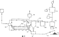
Fig. 8 is another embodiment schematic diagram that is particularly suitable for handling organochlorine insecticide and arsenide.
Fig. 9 is the part side-looking profilograph of the high temperature filtration machine of another kind of form according to the present invention.
Figure 10 is a house steward's shown in Figure 9 side-looking profilograph.
Figure 11 is a kind of side-looking vertical section schematic diagram of condenser that can be used in the embodiment of Fig. 8.
Figure 12 is the side-looking vertical section schematic diagram of another kind of condenser that can be used in the embodiment of Fig. 8.
Figure 13 is the profile that distillates still according to one embodiment of the present invention.
Figure 14 is the modified version that distillates still shown in Figure 13.
With reference to figure 1-3, rotation distillates still 10 and has rotatable cylindrical still wall 11 in the combustion chamber of being located at 12, and combustion chamber 12 is carried out indirect by a plurality of burner 13 heating to distillating still 10 inside.
The pottery magnetic seal distillates in rotation between the stiff end of still wall 11 and combustion chamber 12 (or distillating the still supporting construction) and forms gas-tight seal, in addition in case when causing the discharging of volatility mixture by oxygen in distillating still, the pottery magnetic seal is also as the blast pressure relief opening.(distillate still and preferably have the nitrogen purging) in case block content reaches danger level.
As shown in Figure 3, be provided with fin, blade or like 14 with the stirring that strengthens the material that distillates still to flowing through and promote at the inner surface that distillates still wall 11 by distillating the heat transfer of still wall 11 to material.
Contaminated solid 20 is transported to grizzly 22 by conveyer 21, and excessive particle is removed.Acceptable particle enters through rotary valve 23 and distillates in the still 10.When contaminated efflux of solids when distillating still 10, volatile contaminant is discharged with gas form and is sent to high temperature filtration machine 30 through gas line 15, correlated process will be described in more detail below.The combustion gas heating of high temperature filtration machine origin spontaneous combustion chambers 12 30 (carrying) by pipeline 16.
Solid discharge after rotary valve 17 will be handled is to product receiver 18, and the solid that can be provided with after conveyer 19 will be handled is transported to tip 19A by product receiver 18.
Refer now to Fig. 4, the temperature of keeping high temperature filtration machine 30 recently from distillate still through pipeline 16 add the combustion gas of thermal jackets 31 high more than 500 ℃ in case escaping gas 32 condensations.Escaping gas enters first filter chamber 33 and beats as baffle plate, on first filter chamber 33 and second filter chamber, 35 separated walls 34.Wall 34 can have fin or plate is beneficial to conduct heat and reduce air velocity.Change when escaping gas 32 flows to sharply when first filter chamber 33 flows into second filter chamber 35, the most particles 36 in the escaping gas 32 be collected in the bottom of high temperature filtration machine 30 and by rotary valve 37 and pipeline 38 selective discharge to product receiver 18.The afterbunring gas 32 pottery magnetic of flowing through cross filter core 39 little granule capturing to-1 micron got off.The inside that pottery magnetic is crossed filter core 39 links to each other with plenum chamber 40, and escaping gas 32 is extracted out in the forced-draft chamber by blower fan 41.Blower fan produces partial vacuum in high temperature filtration machine 30 (and distillating still 10), this magnetic seal that helps to make pottery is to distillating the sealing function of still wall 11 ends.On the filter wall, can be provided with a shape blast pressure relief opening 63, open when this shape blast pressure relief opening is designed to blast.
For preventing that the oxygen content in the high temperature filtration machine 30 from reaching danger level,, can will inject pipeline 15 from the nitrogen of basin 42 by the one or more nozzles through linking to each other with valve 43 by sensing device (not shown) monitoring oxygen content and if need.
May be coated in the particle 36 that pottery magnetic is crossed filter core 39 outsides for removing, be connected with an air compressor 44 with house steward 45 through valve 46.Each pipeline 47 stretches into the magnetic of respectively making pottery from house steward 45 and crosses filter core 39 inside, monitoring stream is crossed the sensing device (not shown) of the gas of filter core and valve 46 is operated so that spraying into air stream through pipeline 47 to pottery magnetic filtration in-core portion forms and the opposite counter-flow air of volatility air-flow 32 directions through pottery magnetic, will cross the particulate removal on the filter core and be collected in high temperature filtration machine 30 bottoms.
Fig. 9, Figure 10 represent the high temperature filtration machine that nitrogen is introduced of modified version and removed the equipment of particle on the filter core.Shown in equipment in, nitrogen is added by the house steward 401 with a plurality of outlet 402-406.Each outlet all links to each other with a carrier pipe 407 of locating to stretch into filter above the filter core 39 in mistake.Carrier pipe has a series of downward holes 408, each hole respectively with separately to cross filter core corresponding.So layout can directly be carried nitrogen downwards and be purged filter core and simultaneously nitrogen was transported to filter.
Escaping gas 32 is delivered to afterbunring device 50 (see figure 5)s through pipeline 48, and combustion air is added in the afterbunring device through a plurality of inclination ascending pipes 51 and forms eddy current with the escaping gas active combustion.In one embodiment, enter and run through the pipeline 54 that the pipeline that distillates still 10 inside or conduit 55 link to each other from the combustion gas 52 of the afterbunring device plenum chamber 53 of flowing through.In another embodiment, combustion gas can flow but not flow through and distillate still but enter burner 13 along pipeline 54, shown in the dotted line 62 of Fig. 1.
Refer now to second embodiment of Fig. 6, enter inspissator 121 from the liquid pollutant of liquid storage tank 120 and water content is dropped to minimum, the contaminated liquid after concentrating is transported to jars 122.Contaminated liquid is pumped into spray spout 123 by pump 122a and contaminated liquid is sprayed into distillates still 10.Contaminated liquid contacts volatile contaminant is discharged with gas form as mentioned above with distillating still wall 11 inboards and conduit 55, and any non-volatile solid is discharged into product receiver 18 through rotary valve 17.
Should note pipeline 54 connect afterbunring devices 50 with conduit 55 so that from the combustion gas 52 of afterbunring device with flow through the contaminated liquid that distillates still and be the adverse current form.
Be particularly suitable for handling in the embodiment of refinery tank bottom at Fig. 7, the contaminated refinery products that contain just like 50-80% water are transported to preheater 222 by refinery tank 220.In preheater 222, moisture and light hydrocarbon component evaporate under the temperature more than 120 ℃ for example and enter afterbunring device 50 through pipeline 260.Heat filtering device 261 removes particle and particle is added high temperature filtration machine 30 through rotary valve 262 from water/gas logistics.Spray as previously mentioned from the concentrated liquid of preheater 222 and to distillate in the still 10.Preheater 122 is by heating from the combustion gas that distillates still 10 through pipeline 223.
Non-volatile solid is discharged into receiver 18 through rotary valve 17 from distillating still, and escaping gas is sent to high temperature filtration machine 30.Escaping gas is transported to condenser 270 through pipeline 271 inherent filtration machine 30 under 500 ℃ temperature for example.Gas is cooled, and the condensate liquid oil that acts as a fuel is collected, and it enters jars 272 through pipeline 273 extraction.Condensate liquid can be separated and form by condenser 270 being arranged to " substep distill unit " (for example 300-500 ℃ of following extraction) lubricating oil component through pipeline 275 go to jars 274 and diesel oil alternative compositions (as 200-300 ℃ of following extraction) go to jar 272 through pipeline 273.
Residual volatile material from condenser 270 adds afterbunring device 50 through pipeline 48.These volatile materials and from the water of preheater 222/light HC component can as 1200 ℃ of burnings down, the time of staying for example is 20 seconds.Energy from afterbunring device 50 is recycled, and preheater 223 and high temperature filtration machine 30 are heated.High temperature filtration machine and pretreatment of raw material pipeline and product pipeline all have heating jacket around with holding temperature, and institute's calorific requirement is from the excess gas of combustion chamber.
This method has significantly reduced the disposal cost of refinery tank bottom, and these expenses can be remedied by reclaiming valuable condensate liquid.
Fig. 8 represents to be particularly suitable for handling another embodiment of the invention of the material that contains organochlorine insecticide such as DDT, DDE and DDD and multiple arsyl compound.These materials are found in the soil at domestic animal drinking-water scene.
In this special scheme, preferred at first with contaminated material preheating to remove the moisture in the material.This can adopt preheater 501 to finish.Afterwards material is sent to and distillates still 503, the contaminative compound is vaporized in distillating still.Thereafter the pollutant in the air-flow that will so produce is sent to high temperature filtration machine 504 and further isolates particle from gas, and described high temperature filtration machine can be the filter of the above-mentioned type.The residual gas component is sent to afterbunring device 506.The afterbunring device generates simple combustion product and hydrogen chloride gas with the organochlorine insecticide thermal decomposition.Arsenide in the gas will be basically with the arsenic trioxide form afterbunring device of flowing through.
If the words of expectation add water vapour through pipeline 510 to afterbunring device 506, described water vapour can obtain from preheater 501 easily.Introduce water vapour and cause water/solid/liquid/gas reactions, this helps the generation of hydrogen chloride and arsenate.
After this, air-flow is gone to condenser 512.Gas cools off in condenser rapidly being collected under the arsenate condensation in the jar 514 as granule materials.Air-flow can add in the calcium carbonate in air-flow and hydrogen chloride through hopper 516 after leaving condenser 512.
The gas dust collect plant 518 of can flowing through at last, gas can be discharged into atmosphere thereafter.Can adopt the dust arrester 518 of bag house form to remove in about condensation below 120 ℃ and the particle arsenic trioxide that is collected on the filter medium.Air-flow will and be discharged into atmosphere at about 100 ℃ of following discharge bag houses.Auxiliary blower on the bag house can use to overcome the extra pressure loss of system with high temperature filtration machine fan.In system, adopt each fan of air damper balance.Contaminated particle (arsenic trioxide, spent lime) will be collected in the plastic-lined 200L bucket and handle at the landfill of permitting.
Two kinds of available condenser examples are shown in Figure 11 and 12.Figure 11 represents an evaporation-cooled device, and wherein gas leaves the afterbunring device and flows along inverted-loop tube 601.Be transported to spray head 603 from the shower water of storage tank 602 by pump 604 and spray, before gas leaves condenser, gas is cooled off rapidly.
Figure 12 represents an indirect air cooling device, and gas enters at the top of condenser 700.A series of fans 701 produce traverse condenser air-flow thus before gas is discharged from the bottom with gas cooled.
Figure 13 and 14 represents to be applicable to that two kinds of polytype equipment described herein distillate the still structure.With reference to the accompanying drawings, distillate still 800 and comprise that one is mounted to the cylinder 801 around its axis such as axle 810 rotations.Distillate still 800 and be located in the (not shown) of combustion chamber, the end is sealed by pottery magnetic seal (not shown).Distillate still and be provided with feed end 802 and outlet 803, contaminated material distillates still through this feed end adding.Be provided with polylith floor 808 at cylinder 801 inwalls, floor preferably has 5 ° of oblique angles.
Distillate still 800 and further comprise the ball cage 815 that is located in the cylinder 801.Ball cage 815 comprises a series of horizontal cells or horizon bar 816 and a series of circumferential setting element 817, their the formation co-ordinative construction that fuses.Circumferentially setting element 817 is arranged in pairs in the area of space between the adjacent floor 808.The cross-sectional diameter of ball cage 815 is less than the cross section internal diameter of cylinder 801.Between cylinder 801 and ball cage 815, form annular space 818 thus.
Be provided with a plurality of balls 806 or like in annular space 818, the design of ball or like is used for when each parts rotation interacting with the material fragmentation and remove the carbide that may form on cylinder 801 inwalls with contaminated material.Ball 806 be provided with in groups along the cylinder compartment of terrain and by each to circumferential setting element 817 holding positions.
Further be provided with a series of arms 820 of when each parts rotation, assisting the ball motion in the embodiment depicted in fig. 14.Arm 820 can rotate with ball cage on the axle 810 or also can be fixed on the inwall of cylinder 801.
Ball is provided with in groups, and each is organized ball and keeps its position by ball cage 815, more particularly keeps its position by the element 817 that stretches into gap 818.Ball set is provided with at interval along cylinder.
Attention: no matter to contaminated solid or liquid, flow through distillate still combustion gas 52 logistics can with contaminated material with and stream or reflux type flow.
Afterbunring device gas looped back through pipeline, pipeline or conduit 55 distillate still 10 and make that to distillate the energy of still by burner input minimum.
On pipeline or conduit 55, thermofin is set or floor 56 has not only increased the radiation surface area that distillates still, and helps the bulky grain fragmentation.In addition, pipeloop or conduit also help to form the convection environment that can promote that volatile material removes.The convection current facilitation forms by moving the rotation that distillates still wall and pipeline or conduit 55.
The energy of burner 13 can comprise liquefied petroleum gas, propane, natural gas, recirculation hydro carbons or other energy that is easy to get.
Can comprise hydro carbons, organic chloride, arsenide, hydrogenation hydro carbons, PCB class, tar etc. by the volatile material that method and apparatus of the present invention is handled.
The operating temperature that distillates in the still is decided on handled volatile contaminant and is distillated still and can operate under different temperatures so that can handle different volatile materials in the substep mode.
Can carry out various changes and improvements to described embodiment without departing from the scope of the present invention.
Claims (27)
1. handle the equipment of the volatile material in the contaminated material, it comprises: one distillates the still system, and this system comprises that one is located at the rotatable still that distillates in the combustion chamber to small part, and this combustion chamber has heater to the rotatable still indirect that distillates; Contaminated material is added the feeding device that distillates still; With the material after handling from distillating the discharge device that still is discharged; One afterbunring device; To be sent to the device of afterbunring device burning with the volatile material that gas form is discharged; And combustion gas is sent to from the afterbunring device distillates the still system and distillate the device that is dyed the supplemental heat of material the still by thing to be provided for heating.
2. according to the equipment of claim 1, comprise making combustion gas by distillating the device of still.
3. according to the equipment of claim 1, comprise the device that combustion gas is sent to heater.
4. according to the equipment of aforementioned arbitrary claim, wherein rotation distillates still and can wind from the horizontal by low-angle axle rotation.
5. according to the equipment of arbitrary claim of claim 1 to 4, further comprise make distillate the still end with around the isolated pottery magnetic end sealing in the combustion chamber that distillates still.
6. according to the equipment of arbitrary claim of claim 1 to 5, wherein said heater comprises one or more to distillating the burner of still indirect.
7. according to the equipment of aforementioned arbitrary claim, wherein when contaminated material is solid material, said feeding device comprises the grizzly that removes oversized particles or particle or screening plant and contaminated solid selectivity is added the rotary valve that distillates still.
8. according to the equipment of claim 7, further be included between the source and grizzly or screening plant of contaminated solid, be used for reducing the lapping device of contaminated solids size.
9. according to the equipment of arbitrary claim of claim 1 to 5, wherein when said material comprises liquid, feeding device comprises and removes or reduce the separator of contaminated liquid water content or preheater and concentrated liquid added the spray equipment that distillates still.
10. according to the equipment of arbitrary claim of claim 1 to 9, wherein discharge device comprises the rotary valve of the material selective discharge after handling to the product receiver.
11. the equipment according to arbitrary claim of claim 1 to 10 further comprises the high temperature filtration machine that removes particle.
12. be used to handle the high temperature filtration machine of volatile gaseous contaminated material, this high temperature filtration machine comprises: have the main body of first and second filter chambers, wherein these filter chambers comprise a upper area and zone, a bottom when filter is in operating position; Be positioned at the passage that filter chamber's lower area is communicated with each filter chamber; The inlet that the contaminated material of gaseous state is added first filter chamber at filter chamber's upper area; Outlet from second filter chamber discharging gaseous state material; Be positioned near the solid collection district of passage; Solids exhaust outlet from solid collection district discharging solid; The filter that and interval relative with above-mentioned inlet is provided with, feeding gas impacts the baffle plate on it and the gaseous state material that flows out second filter chamber through outlet is filtered.
13. according to the high temperature filtration machine of claim 12, wherein said baffle plate is limited by the wall of separating above-mentioned first and second filter chambers.
14. according to the high temperature filtration machine of claim 13, wherein said wall extends and ends at from filter chamber's inner roof wall and leaves lower inner wall a distance, described filter chamber, the space between wall and the lower inner wall forms above-mentioned passage.
15. according to the high temperature filtration machine of arbitrary claim of claim 12 to 14, wherein said exhaust outlet comprises a plurality of outlet openings that are positioned on above-mentioned second filter chamber's roof.
16. according to the high temperature filtration machine of claim 15, wherein said filter comprises that a plurality of pottery magnetic cross filter core, each magnetic of making pottery is crossed filter core and is all linked with separately outlet, and said pottery magnetic is crossed filter core and extended into above-mentioned second filter chamber.
17., comprise that reception is from the gas collection chamber of the gas material of outlet with from the exhaust outlet of gas collection chamber's emission gases material according to the high temperature filtration machine of arbitrary claim of claim 12 to 16.
18., further comprise through the blower fan device of outlet from second filter chamber's intake-gas material according to the high temperature filtration machine of arbitrary claim of claim 12 to 17.
19., further comprise the palsating equipment of carrying air pressure that filter is cleaned to filter with proper flow in the other direction according to the high temperature filtration machine of arbitrary claim of claim 12 to 18.
20. according to the high temperature filtration machine of arbitrary claim of claim 12 to 19, wherein used gas is nitrogen in the palsating equipment.
21. the high temperature filtration machine according to arbitrary claim of claim 12 to 20 further comprises to the thermal jacket of small part around the filter main body.
22. be used for handling the equipment of the contaminated material volatile material that comprises organochlorine insecticide and arsyl compound, it comprises:
One distillates the still system, this system comprises a rotatable still that distillates that is located in the combustion chamber of being heated by heater to small part, has feed end and outlet, material adds through described feed end and distillates still, in use makes contaminated material thus and distillates the still wall and contact volatile material is discharged with gas form;
Reception is from the high temperature filtration machine of the material that distillates still, with the afterbunring device of gas combustion and device from water vapour to the afterbunring device that introduce.
23., be included in material and enter and distillate still, water vapour and move into before the afterbunring device heater to the material preheating from described heater according to the equipment of claim 22.
24. be used to handle the still that distillates of volatile material, this distillates still and comprises: one is mounted to the cylinder around its longitudinal axis rotation, and said cylinder has feed end and outlet; One combustion chamber, said cylinder to small part is positioned at the combustion chamber; Be located in the cylinder, be used for when cylinder rotate with the interaction of contaminated material with the material fragmentation and remove a plurality of balls or the like of the carbide that may on the cylinder inwall, form.
25. the still that distillates according to claim 24 further comprises the ball cage that is positioned at said cylinder, said ball is located in the space between said ball cage and the above-mentioned cylindrical inner surface.
26. according to the still that distillates of claim 25, wherein said ball is provided with in groups, ball set is provided with at interval along cylinder.
27. according to the still that distillates of claim 26, wherein said ball cage is mounted to the direction rotation opposite with above-mentioned cylinder.
Applications Claiming Priority (2)
| Application Number | Priority Date | Filing Date | Title |
|---|---|---|---|
| AUPN5857 | 1995-10-06 | ||
| AUPN5857A AUPN585795A0 (en) | 1995-10-06 | 1995-10-06 | Volatile materials treatment system |
Publications (1)
| Publication Number | Publication Date |
|---|---|
| CN1201410A true CN1201410A (en) | 1998-12-09 |
Family
ID=3790185
Family Applications (1)
| Application Number | Title | Priority Date | Filing Date |
|---|---|---|---|
| CN96198130A Pending CN1201410A (en) | 1995-10-06 | 1996-10-04 | Volatile materials treatment system |
Country Status (13)
| Country | Link |
|---|---|
| US (2) | US6213030B1 (en) |
| EP (1) | EP0865330B1 (en) |
| JP (1) | JPH11514429A (en) |
| KR (1) | KR19990064071A (en) |
| CN (1) | CN1201410A (en) |
| AT (1) | ATE231421T1 (en) |
| AU (1) | AUPN585795A0 (en) |
| DE (1) | DE69625928D1 (en) |
| ES (1) | ES2194113T3 (en) |
| MX (1) | MX9802692A (en) |
| NZ (1) | NZ318737A (en) |
| TW (1) | TW319818B (en) |
| WO (1) | WO1997013594A1 (en) |
Cited By (13)
| Publication number | Priority date | Publication date | Assignee | Title |
|---|---|---|---|---|
| CN102069088A (en) * | 2010-11-23 | 2011-05-25 | 南京农业大学 | System for repairing organic contaminated soil by soil ventilation-vertical desorption furnace |
| CN102284473A (en) * | 2011-06-03 | 2011-12-21 | 中国环境科学研究院 | Drum type soil thermal desorption repair system |
| CN103495598A (en) * | 2013-10-18 | 2014-01-08 | 洛阳水泥工程设计研究院有限公司 | Organically-polluted soil remediation method |
| CN104215066A (en) * | 2014-09-04 | 2014-12-17 | 郴州杉杉新材料有限公司 | Horizontal-tube carbon intermediate continuous thermal treatment device |
| CN104815842A (en) * | 2014-12-10 | 2015-08-05 | 北京建工环境修复股份有限公司 | Skid-mounted thermal soil separation device |
| CN105127191A (en) * | 2015-09-23 | 2015-12-09 | 深圳文科园林股份有限公司 | Restoration device and method for volatile contaminated soil |
| CN108746179A (en) * | 2018-07-17 | 2018-11-06 | 贵州省环境科学研究设计院 | A kind of combustion chamber and its combustion method for modularization soil demercuration |
| CN109692869A (en) * | 2019-02-22 | 2019-04-30 | 杰瑞环保科技有限公司 | The rotary indirect thermal desorption device of one kind and system |
| CN111215439A (en) * | 2019-10-11 | 2020-06-02 | 广西博世科环保科技股份有限公司 | Method and device for controlling oxygen content of tail gas of thermal desorption system of organic contaminated soil |
| CN112238134A (en) * | 2020-09-23 | 2021-01-19 | 刘俊燕 | Soil remediation thermal desorption barrel |
| CN113564346A (en) * | 2020-11-12 | 2021-10-29 | 广东天源环境科技有限公司 | High-arsenic metal mineral powder dearsenification equipment and method with gradually-distributed flue gas inlets |
| CN115121597A (en) * | 2022-06-29 | 2022-09-30 | 国网河北省电力有限公司电力科学研究院 | Vehicle-mounted van-type continuous microwave soil solid waste treatment equipment |
| CN116060574A (en) * | 2023-04-07 | 2023-05-05 | 山西金瑞高压环件有限公司 | Chamber type natural gas energy-saving emission-reducing forging heating furnace |
Families Citing this family (52)
| Publication number | Priority date | Publication date | Assignee | Title |
|---|---|---|---|---|
| JPH1096507A (en) * | 1996-08-02 | 1998-04-14 | Yamaichi Kinzoku Kk | Waste resin-processing burner |
| ES2157715B1 (en) * | 1998-03-12 | 2002-03-01 | Simo Antonio Belenguer | TUBULAR OVEN FOR CONTROLLED ATMOSPHERE POOLISIS OF PRODUCTS THAT DECOMPOSE AT LESS THAN 500 C AND RECOVERY OF THE INERT SOLIDS THAT ACCOMPANY YOU. |
| HU225373B1 (en) * | 1998-04-17 | 2006-10-28 | Allan Dr Inovius | Method and apparatus for the prevention of global warming, through elimination of hazardous exhaust gases of waste and/or fuel burners |
| AUPP618598A0 (en) * | 1998-09-28 | 1998-10-22 | Innova Soil Technology Pty Ltd | Soil remediation system |
| JP3266591B2 (en) * | 1999-12-10 | 2002-03-18 | アートセラミック株式会社 | Intermittent flow type pyrolysis equipment |
| IT1318321B1 (en) * | 2000-02-18 | 2003-08-25 | Tesi Ambiente S R L | PLANT FOR THE TREATMENT OF WASTE FUELS. |
| JP2002219437A (en) * | 2001-01-25 | 2002-08-06 | Kumagawa:Kk | Dust and ash treating equipment |
| JP3961795B2 (en) * | 2001-08-22 | 2007-08-22 | 株式会社神戸製鋼所 | Combustion treatment method and apparatus for combustible waste |
| US6638396B1 (en) * | 2002-11-04 | 2003-10-28 | Jim S. Hogan | Method and apparatus for processing a waste product |
| US20100187178A1 (en) * | 2003-01-29 | 2010-07-29 | Molycorp Minerals, Llc | Process for removing and sequestering contaminants from aqueous streams |
| US6863825B2 (en) | 2003-01-29 | 2005-03-08 | Union Oil Company Of California | Process for removing arsenic from aqueous streams |
| US8211319B2 (en) * | 2003-09-16 | 2012-07-03 | Bp Corporation North America Inc. | Solid-liquid separation process |
| US7669349B1 (en) | 2004-03-04 | 2010-03-02 | TD*X Associates LP | Method separating volatile components from feed material |
| ITMI20042242A1 (en) * | 2004-11-19 | 2005-02-19 | Vomm Chemipharma Srl | METHOD FOR RECLAMATION OF SOIL POLLUTED BY POLIALOGENATED HYDROCARBONS |
| CA2631370A1 (en) * | 2005-12-05 | 2007-06-14 | Struan Glen Robertson | Apparatus for treating materials |
| CA2531873C (en) * | 2006-01-03 | 2007-07-31 | Maurice Chambe | Process and device for thermal treatment of organic materials |
| US7812206B2 (en) | 2006-03-21 | 2010-10-12 | Bp Corporation North America Inc. | Apparatus and process for the separation of solids and liquids |
| US8066874B2 (en) * | 2006-12-28 | 2011-11-29 | Molycorp Minerals, Llc | Apparatus for treating a flow of an aqueous solution containing arsenic |
| US7662217B2 (en) * | 2007-04-03 | 2010-02-16 | Battelle Energy Alliance, Llc | Soil separator and sampler and method of sampling |
| US8252087B2 (en) * | 2007-10-31 | 2012-08-28 | Molycorp Minerals, Llc | Process and apparatus for treating a gas containing a contaminant |
| US20090107925A1 (en) * | 2007-10-31 | 2009-04-30 | Chevron U.S.A. Inc. | Apparatus and process for treating an aqueous solution containing biological contaminants |
| US8349764B2 (en) | 2007-10-31 | 2013-01-08 | Molycorp Minerals, Llc | Composition for treating a fluid |
| US20090107919A1 (en) * | 2007-10-31 | 2009-04-30 | Chevron U.S.A. Inc. | Apparatus and process for treating an aqueous solution containing chemical contaminants |
| US8530716B2 (en) * | 2008-08-14 | 2013-09-10 | Bp Corporation North America Inc. | Melt-crystallization separation and purification process |
| US8168043B2 (en) * | 2008-08-29 | 2012-05-01 | Eau-Viron Incorporated | Retort apparatus and method for continuously processing liquid and solid mixtures and for recovering products therefrom |
| TW201038510A (en) * | 2009-03-16 | 2010-11-01 | Molycorp Minerals Llc | Porous and durable ceramic filter monolith coated with a rare earth for removing contaminates from water |
| US8646415B2 (en) * | 2009-03-18 | 2014-02-11 | Ex-Tar Technologies | System and method for zero liquid discharge |
| PE20121145A1 (en) * | 2009-04-09 | 2012-08-30 | Molycorp Minerals Llc | PROCESS FOR THE REMOVAL OF ONE OR MORE CONTAMINANTS FROM AN ELECTRO-REFINING SOLUTION USING RARE EARTH METALS |
| EA201200082A1 (en) * | 2009-07-02 | 2012-07-30 | Гершон Бен-Товим | DRYER |
| JP5288623B2 (en) * | 2009-07-09 | 2013-09-11 | 日工株式会社 | Heat purification method for contaminated soil |
| US20120199466A1 (en) * | 2009-09-07 | 2012-08-09 | Ivan Yurjevich Tsyhankov | Plant for processing of carbon-containing raw material |
| MX2012005351A (en) * | 2009-11-09 | 2012-11-23 | Molycorp Minerals Llc | Rare earth removal of colorants. |
| IT1403900B1 (en) * | 2011-01-19 | 2013-11-08 | Technelep Srl | MULTI-PURPOSE THERMOVALORIZATION PLANT OF BIOLOGICAL SLUDGE ORGANIC WASTE AND BIOMASS MINUTES |
| US9233863B2 (en) | 2011-04-13 | 2016-01-12 | Molycorp Minerals, Llc | Rare earth removal of hydrated and hydroxyl species |
| ITMI20130919A1 (en) * | 2013-06-05 | 2014-12-06 | Greentek Di Salomoni Marco & C S N C | PLANT FOR ENERGY PRODUCTION STARTING FROM BIOMASSES |
| KR101523028B1 (en) * | 2014-01-21 | 2015-05-26 | 녹원종합기술 주식회사 | The pyrolysis and carbonization system of waste |
| MX370462B (en) | 2014-03-07 | 2019-12-13 | Secure Natural Resources Llc | Cerium (iv) oxide with exceptional arsenic removal properties. |
| CN105953576B (en) * | 2016-06-30 | 2017-12-29 | 苏州新智机电工业有限公司 | A kind of split type ir tunnel furnace apparatus |
| GB2553771B (en) | 2016-09-08 | 2018-12-05 | Wilson Bio Chemical Ltd | Removing particulates |
| CN106890528A (en) * | 2017-03-14 | 2017-06-27 | 张镇龙 | High-temperature dust removal equipment |
| EP3806975A1 (en) * | 2018-06-13 | 2021-04-21 | Cargill, Incorporated | Liquid discharge filter and its use |
| CN110094738A (en) * | 2019-05-27 | 2019-08-06 | 邯郸开发区华骐环保科技有限公司 | A kind of waste incineration cylinder can effectively reduce flue dust |
| CN112301224A (en) * | 2019-08-02 | 2021-02-02 | 江苏华久特钢工具有限公司 | Grinding wheel ash tungsten-molybdenum alloy extraction technology and equipment thereof |
| CN110327730A (en) * | 2019-08-20 | 2019-10-15 | 贵州劲嘉新型包装材料有限公司 | A kind of cold wave unit filter plant |
| CN111266398B (en) * | 2020-01-22 | 2022-01-25 | 上海吾励环境技术有限公司 | Soil ex-situ remediation external heat double-position spiral type drying roasting kiln |
| CN112076554A (en) * | 2020-09-14 | 2020-12-15 | 中北大学 | Dust-explosion-proof dust removal equipment for workshop |
| CN112683078B (en) * | 2020-12-04 | 2022-07-29 | 上海天汉环境资源有限公司 | Device for recycling steam condensate water in jacket of evaporation kettle |
| CN113648775A (en) * | 2021-09-17 | 2021-11-16 | 华东理工大学 | Gas cooling-washing device and method |
| CN114272710A (en) * | 2021-11-16 | 2022-04-05 | 新兴铸管股份有限公司 | Core-making sand pipeline gas purification system |
| CN114590607B (en) * | 2022-03-09 | 2024-03-19 | 上海电气集团股份有限公司 | Slag discharging system for high-temperature ash and using method thereof |
| CN116650871B (en) * | 2023-07-26 | 2023-10-17 | 山西红清蓝环保工程有限公司 | Foam nickel flame arrester with self-cleaning function |
| CN117208995B (en) * | 2023-09-22 | 2024-04-05 | 山东省物化探勘查院 | Gas-liquid separation device based on volatile organic pollutants in groundwater |
Family Cites Families (42)
| Publication number | Priority date | Publication date | Assignee | Title |
|---|---|---|---|---|
| US2845822A (en) * | 1953-11-05 | 1958-08-05 | Blaw Knox Co | Indexing mechanism |
| US3787292A (en) * | 1971-08-13 | 1974-01-22 | E Keappler | Apparatus for pyrolysis of wastes |
| US3792671A (en) * | 1972-05-17 | 1974-02-19 | Clean Air Ator Corp | Incinerator with afterburner |
| US3877899A (en) * | 1972-09-28 | 1975-04-15 | Richard P Bundy | Apparatus for separating particulate matter from a gas stream |
| US4052266A (en) * | 1973-05-11 | 1977-10-04 | Griffith Joseph W | Method and apparatus for purifying process waste emissions |
| DE2356294A1 (en) * | 1973-11-10 | 1975-05-15 | Air Preheater | Refuse incinerator with gasifier and burner - prevents oxidation of metallic refuse and uses afterburner heat for oxidation |
| DE2518128C3 (en) | 1975-04-24 | 1978-11-16 | Kernforschungsanlage Juelich Gmbh, 5170 Juelich | Process for cleaning flue gases arising in incineration plants and incineration plants |
| DE2651302C3 (en) | 1976-05-12 | 1981-07-09 | PLS Gesellschaft für Pyrolyse-Müllverwertungsverfahren mbH, 8000 München | Device for generating distillation gas from waste |
| SE413845B (en) * | 1977-08-31 | 1980-06-30 | Bahco Ventilation Ab | DEVICE ON THE DUST POCKET OF A COPACT FILTER |
| US4404152A (en) * | 1980-11-24 | 1983-09-13 | Phillips Petroleum Company | Iron-containing refractory balls for retorting oil shale |
| SE426915B (en) * | 1981-02-10 | 1983-02-21 | Patronax Ab | FILTERING DEVICE WITH SLAUGHTER MECHANISM THAT ALLOWS CLEANING OF A SUBSTANTABLE FILTERING MEDIUM FROM AIR-SEPARATED DUST |
| US4563246A (en) * | 1983-05-17 | 1986-01-07 | Pedco, Inc. | Apparatus for retorting particulate solids having recoverable volatile constituents |
| DE3335999A1 (en) * | 1983-10-04 | 1985-04-04 | Hölter, Heinz, Dipl.-Ing., 4390 Gladbeck | Dust diffuser arrangement in fabric filters |
| US4582044A (en) * | 1984-01-19 | 1986-04-15 | Vermont Castings, Inc. | Clean burning exterior retrofit system for solid fuel heating appliances |
| DE3447079A1 (en) * | 1984-08-28 | 1986-03-06 | Carl Still Gmbh & Co Kg, 4350 Recklinghausen | Process for thermally treating contaminated soil |
| NZ222007A (en) * | 1986-10-02 | 1989-01-27 | Neutralysis Ind Pty Ltd | Treating waste material by pelletising and vitrifying |
| US4865627A (en) * | 1987-10-30 | 1989-09-12 | Shell Oil Company | Method and apparatus for separating fine particulates from a mixture of fine particulates and gas |
| DE3741623A1 (en) * | 1987-12-04 | 1989-06-15 | Salzgitter Ag | Pyrolysis of bitumen in a reactor containing grinding medium |
| US4827854A (en) * | 1988-05-16 | 1989-05-09 | Collette Jerry R | Reflux volatilization system |
| WO1989012783A1 (en) * | 1988-06-17 | 1989-12-28 | American Combustion, Inc. | A method and apparatus for waste disposal |
| US5199354A (en) * | 1988-11-18 | 1993-04-06 | Tps Technologies, Inc. | Mobile soil remediation system |
| US5318606A (en) * | 1989-04-04 | 1994-06-07 | Pall Corporation | Filtration system |
| US5265545A (en) * | 1989-04-12 | 1993-11-30 | Miltox Holdings Pte, Limited | Method and apparatus for waste treatment |
| US4934286A (en) * | 1989-08-24 | 1990-06-19 | Fowler Benjamin P | Apparatus and method for the disposal of waste |
| US5082534A (en) * | 1990-03-14 | 1992-01-21 | Wayne Technology, Inc. | Pyrolytic conversion system |
| GB9007319D0 (en) * | 1990-03-31 | 1990-05-30 | Copermill Ltd | Rotary melting furnace |
| US5228803A (en) * | 1990-06-12 | 1993-07-20 | Richard A. Crosby | Apparatus and method for thermally stripping volatile organic compounds from soil using a recirculating combustible gas |
| US5207176A (en) * | 1990-11-20 | 1993-05-04 | Ici Explosives Usa Inc | Hazardous waste incinerator and control system |
| US5164158A (en) * | 1990-12-14 | 1992-11-17 | Thermotech Systems Corporation | Methods for remediating contaminated soils |
| US5087277A (en) * | 1991-03-28 | 1992-02-11 | Virginia Polytechnic Institute | High temperature ceramic particulate filter |
| CN1039099C (en) | 1992-01-16 | 1998-07-15 | 国际壳牌研究有限公司 | An apparatus for filtering solid particles from a fluid |
| US5256175A (en) * | 1992-03-04 | 1993-10-26 | Zievers James F | Hot gas filter |
| DE4210926A1 (en) * | 1992-04-02 | 1993-10-07 | Ebf Beratungs Und Forschungsge | Demountable modular pyrolysis installation - for purificn. of organics-contaminated earth, with heat recovery and exhaust gas scrubbing |
| US5220873A (en) * | 1992-07-22 | 1993-06-22 | Covenant Environmental Technologies, Inc. | Apparatus for retorting organic matter |
| DE4235412A1 (en) * | 1992-10-21 | 1994-04-28 | Metallgesellschaft Ag | Process for gasifying waste materials containing combustible components |
| CA2151918A1 (en) | 1992-12-18 | 1994-07-07 | Struan Glen Robertson | Treatment of toxic waste |
| US5393501A (en) * | 1993-10-13 | 1995-02-28 | Cedarapids, Inc. | Material remediation in multi-function heating drum |
| US5482537A (en) * | 1994-05-18 | 1996-01-09 | A. Ahlstrom Corporation | Gas filtering apparatus |
| US5531798A (en) * | 1994-05-26 | 1996-07-02 | Foster Wheeler Energia Oy | Eliminating ash bridging in ceramic filters |
| US5579704A (en) * | 1994-12-27 | 1996-12-03 | Mansur Industries Inc. | Apparatus for disposing of refuse by thermal oxidation |
| US5917064A (en) * | 1996-01-02 | 1999-06-29 | Industrial Filter & Pump Mfg. Co. | Filter with heated tube sheet |
| US6077490A (en) * | 1999-03-18 | 2000-06-20 | Mcdermott Technology, Inc. | Method and apparatus for filtering hot syngas |
-
1995
- 1995-10-06 AU AUPN5857A patent/AUPN585795A0/en not_active Abandoned
-
1996
- 1996-10-02 TW TW085111992A patent/TW319818B/zh active
- 1996-10-04 JP JP9514566A patent/JPH11514429A/en not_active Ceased
- 1996-10-04 DE DE69625928T patent/DE69625928D1/en not_active Expired - Lifetime
- 1996-10-04 AT AT96931689T patent/ATE231421T1/en not_active IP Right Cessation
- 1996-10-04 CN CN96198130A patent/CN1201410A/en active Pending
- 1996-10-04 WO PCT/AU1996/000628 patent/WO1997013594A1/en not_active Application Discontinuation
- 1996-10-04 KR KR1019980702550A patent/KR19990064071A/en not_active Application Discontinuation
- 1996-10-04 ES ES96931689T patent/ES2194113T3/en not_active Expired - Lifetime
- 1996-10-04 NZ NZ318737A patent/NZ318737A/en unknown
- 1996-10-04 US US09/051,004 patent/US6213030B1/en not_active Expired - Fee Related
- 1996-10-04 EP EP96931689A patent/EP0865330B1/en not_active Expired - Lifetime
-
1998
- 1998-04-06 MX MX9802692A patent/MX9802692A/en unknown
-
2000
- 2000-09-28 US US09/675,127 patent/US6341567B1/en not_active Expired - Fee Related
Cited By (19)
| Publication number | Priority date | Publication date | Assignee | Title |
|---|---|---|---|---|
| CN102069088B (en) * | 2010-11-23 | 2012-07-04 | 南京农业大学 | System for repairing organic contaminated soil by soil ventilation-vertical desorption furnace |
| CN102069088A (en) * | 2010-11-23 | 2011-05-25 | 南京农业大学 | System for repairing organic contaminated soil by soil ventilation-vertical desorption furnace |
| CN102284473A (en) * | 2011-06-03 | 2011-12-21 | 中国环境科学研究院 | Drum type soil thermal desorption repair system |
| CN103495598B (en) * | 2013-10-18 | 2016-02-10 | 洛阳水泥工程设计研究院有限公司 | A kind of Organically-pollutedsoil soil remediation method |
| CN103495598A (en) * | 2013-10-18 | 2014-01-08 | 洛阳水泥工程设计研究院有限公司 | Organically-polluted soil remediation method |
| CN104215066A (en) * | 2014-09-04 | 2014-12-17 | 郴州杉杉新材料有限公司 | Horizontal-tube carbon intermediate continuous thermal treatment device |
| CN104215066B (en) * | 2014-09-04 | 2015-12-09 | 郴州杉杉新材料有限公司 | A kind of horizontal tube carbonaceous intermediate apparatus for continous heat treatment |
| CN104815842A (en) * | 2014-12-10 | 2015-08-05 | 北京建工环境修复股份有限公司 | Skid-mounted thermal soil separation device |
| CN105127191A (en) * | 2015-09-23 | 2015-12-09 | 深圳文科园林股份有限公司 | Restoration device and method for volatile contaminated soil |
| CN108746179A (en) * | 2018-07-17 | 2018-11-06 | 贵州省环境科学研究设计院 | A kind of combustion chamber and its combustion method for modularization soil demercuration |
| WO2020168875A1 (en) * | 2019-02-22 | 2020-08-27 | 杰瑞环保科技有限公司 | Rotary indirect thermal desorption device and system |
| CN109692869A (en) * | 2019-02-22 | 2019-04-30 | 杰瑞环保科技有限公司 | The rotary indirect thermal desorption device of one kind and system |
| CN111215439A (en) * | 2019-10-11 | 2020-06-02 | 广西博世科环保科技股份有限公司 | Method and device for controlling oxygen content of tail gas of thermal desorption system of organic contaminated soil |
| CN112238134A (en) * | 2020-09-23 | 2021-01-19 | 刘俊燕 | Soil remediation thermal desorption barrel |
| CN113564346A (en) * | 2020-11-12 | 2021-10-29 | 广东天源环境科技有限公司 | High-arsenic metal mineral powder dearsenification equipment and method with gradually-distributed flue gas inlets |
| CN113564346B (en) * | 2020-11-12 | 2022-09-09 | 广东天源环境科技有限公司 | High-arsenic metal mineral powder dearsenification equipment and method with gradually-distributed flue gas inlets |
| CN115121597A (en) * | 2022-06-29 | 2022-09-30 | 国网河北省电力有限公司电力科学研究院 | Vehicle-mounted van-type continuous microwave soil solid waste treatment equipment |
| CN115121597B (en) * | 2022-06-29 | 2023-08-22 | 国网河北省电力有限公司电力科学研究院 | Vehicle-mounted van-type continuous microwave soil solid waste treatment equipment |
| CN116060574A (en) * | 2023-04-07 | 2023-05-05 | 山西金瑞高压环件有限公司 | Chamber type natural gas energy-saving emission-reducing forging heating furnace |
Also Published As
| Publication number | Publication date |
|---|---|
| EP0865330B1 (en) | 2003-01-22 |
| NZ318737A (en) | 1999-07-29 |
| DE69625928D1 (en) | 2003-02-27 |
| EP0865330A4 (en) | 2000-08-16 |
| US6341567B1 (en) | 2002-01-29 |
| JPH11514429A (en) | 1999-12-07 |
| US6213030B1 (en) | 2001-04-10 |
| ATE231421T1 (en) | 2003-02-15 |
| KR19990064071A (en) | 1999-07-26 |
| EP0865330A1 (en) | 1998-09-23 |
| MX9802692A (en) | 1998-11-30 |
| TW319818B (en) | 1997-11-11 |
| WO1997013594A1 (en) | 1997-04-17 |
| ES2194113T3 (en) | 2003-11-16 |
| AUPN585795A0 (en) | 1995-11-02 |
Similar Documents
| Publication | Publication Date | Title |
|---|---|---|
| CN1201410A (en) | Volatile materials treatment system | |
| US4715965A (en) | Method for separating and recovering volatilizable contaminants from soil | |
| CN1065156C (en) | Method and apparatus for hot resolution of waste material | |
| AU727756B2 (en) | Process and apparatus for treating process streams from a system for separating constituents from contaminated material | |
| CN111566187A (en) | Thermal decomposition emulsifying system for plastic | |
| CN1786570A (en) | Complete equipment for cremating waste and method for comprehensive utilization of waste | |
| CN207143067U (en) | A kind of oil plant oily sludge disposal system | |
| CN107500501A (en) | A kind of oil plant oily sludge disposal system and method | |
| CN108625821A (en) | Oil-based drill cuttings processing method | |
| CN109692869A (en) | The rotary indirect thermal desorption device of one kind and system | |
| ES2354706T3 (en) | METHOD OF REMEDIATION OF SOILS CONTAMINATED WITH POLYHALOGENATED HYDROCARBONS. | |
| CN110180882A (en) | It is a kind of for handling the thermal desorption device of mercury contaminated soil | |
| CN1342319A (en) | Apparatus for separation of constituents from matrices | |
| CN1231700C (en) | Incinerator for waste disposal | |
| US5261936A (en) | Gas treating apparatus | |
| US7514049B2 (en) | Method and apparatus for thermal phase separation | |
| RU2005115198A (en) | METHOD FOR PROCESSING RUBBER-CONTAINING WASTE AND INSTALLATION FOR ITS IMPLEMENTATION (OPTIONS) | |
| CN106216380A (en) | A kind of High Efficiency Thermal desorption repairs mercurous pollution treatment system and method | |
| AU712838B2 (en) | Volatile materials treatment system | |
| US3884768A (en) | Reclamation of non-combustible liquids by direct flame vaporization, centrifugal solids separation and subsequent condensation | |
| CN209334434U (en) | High oil-contaminated soil restoration processing system | |
| CA2233661C (en) | Volatile materials treatment system | |
| AU705861B2 (en) | Volatile materials treatment system | |
| EP0857520A1 (en) | Treatment of contaminated soil | |
| JP3532435B2 (en) | Pollutant treatment method and treatment device |
Legal Events
| Date | Code | Title | Description |
|---|---|---|---|
| C06 | Publication | ||
| PB01 | Publication | ||
| C10 | Entry into substantive examination | ||
| SE01 | Entry into force of request for substantive examination | ||
| AD01 | Patent right deemed abandoned | ||
| C20 | Patent right or utility model deemed to be abandoned or is abandoned |