CN116141296A - Industrial robot's forearm and industrial robot - Google Patents
Industrial robot's forearm and industrial robot Download PDFInfo
- Publication number
- CN116141296A CN116141296A CN202310426523.1A CN202310426523A CN116141296A CN 116141296 A CN116141296 A CN 116141296A CN 202310426523 A CN202310426523 A CN 202310426523A CN 116141296 A CN116141296 A CN 116141296A
- Authority
- CN
- China
- Prior art keywords
- arm
- industrial robot
- fixedly connected
- rack
- connecting rod
- Prior art date
- Legal status (The legal status is an assumption and is not a legal conclusion. Google has not performed a legal analysis and makes no representation as to the accuracy of the status listed.)
- Granted
Links
Images


Classifications
-
- B—PERFORMING OPERATIONS; TRANSPORTING
- B25—HAND TOOLS; PORTABLE POWER-DRIVEN TOOLS; MANIPULATORS
- B25J—MANIPULATORS; CHAMBERS PROVIDED WITH MANIPULATION DEVICES
- B25J9/00—Programme-controlled manipulators
-
- B—PERFORMING OPERATIONS; TRANSPORTING
- B25—HAND TOOLS; PORTABLE POWER-DRIVEN TOOLS; MANIPULATORS
- B25J—MANIPULATORS; CHAMBERS PROVIDED WITH MANIPULATION DEVICES
- B25J15/00—Gripping heads and other end effectors
- B25J15/06—Gripping heads and other end effectors with vacuum or magnetic holding means
- B25J15/0616—Gripping heads and other end effectors with vacuum or magnetic holding means with vacuum
-
- B—PERFORMING OPERATIONS; TRANSPORTING
- B25—HAND TOOLS; PORTABLE POWER-DRIVEN TOOLS; MANIPULATORS
- B25J—MANIPULATORS; CHAMBERS PROVIDED WITH MANIPULATION DEVICES
- B25J9/00—Programme-controlled manipulators
- B25J9/10—Programme-controlled manipulators characterised by positioning means for manipulator elements
- B25J9/102—Gears specially adapted therefor, e.g. reduction gears
- B25J9/1035—Pinion and fixed rack drivers, e.g. for rotating an upper arm support on the robot base
-
- B—PERFORMING OPERATIONS; TRANSPORTING
- B25—HAND TOOLS; PORTABLE POWER-DRIVEN TOOLS; MANIPULATORS
- B25J—MANIPULATORS; CHAMBERS PROVIDED WITH MANIPULATION DEVICES
- B25J9/00—Programme-controlled manipulators
- B25J9/10—Programme-controlled manipulators characterised by positioning means for manipulator elements
- B25J9/14—Programme-controlled manipulators characterised by positioning means for manipulator elements fluid
- B25J9/144—Linear actuators
-
- Y—GENERAL TAGGING OF NEW TECHNOLOGICAL DEVELOPMENTS; GENERAL TAGGING OF CROSS-SECTIONAL TECHNOLOGIES SPANNING OVER SEVERAL SECTIONS OF THE IPC; TECHNICAL SUBJECTS COVERED BY FORMER USPC CROSS-REFERENCE ART COLLECTIONS [XRACs] AND DIGESTS
- Y02—TECHNOLOGIES OR APPLICATIONS FOR MITIGATION OR ADAPTATION AGAINST CLIMATE CHANGE
- Y02P—CLIMATE CHANGE MITIGATION TECHNOLOGIES IN THE PRODUCTION OR PROCESSING OF GOODS
- Y02P90/00—Enabling technologies with a potential contribution to greenhouse gas [GHG] emissions mitigation
- Y02P90/02—Total factory control, e.g. smart factories, flexible manufacturing systems [FMS] or integrated manufacturing systems [IMS]
Landscapes
- Engineering & Computer Science (AREA)
- Robotics (AREA)
- Mechanical Engineering (AREA)
- Manipulator (AREA)
Abstract
The invention discloses a forearm of an industrial robot, which comprises a telescopic cylinder and an arm box, wherein the telescopic cylinder consists of a cylinder seat and a cylinder arm, the cylinder arm penetrates through the arm box in a sliding manner, two opposite side walls of the arm box are respectively provided with a rotating groove, gears are rotationally connected in the rotating grooves, and the side walls of the gears are fixedly connected with a protective box plate; the invention also discloses an industrial robot, which comprises the small arm of the industrial robot, a moving slide rail, a slide seat and a suspension rod, wherein the slide seat slides along the moving slide rail, and the upper end and the lower end of the suspension rod are fixedly connected with the slide seat and the arm box respectively. According to the invention, the gear, the rack and the protective box plates are arranged, so that after the telescopic cylinder drives the sucker and the product to rise into the arm box, the rack pulls the gear to rotate, and the two protective box plates can be driven to be combined and form a closed space with the arm box, and the product can be completely prevented from falling to the ground due to falling off from the sucker.
Description
Technical Field
The invention relates to the technical field of industrial robots, in particular to a small arm of an industrial robot and the industrial robot.
Background
In the field of modern industrial production, robots are common intelligent devices, and can effectively replace manual operation, wherein in the manufacturing process of semiconductors, electronic chips and wafers, the robots are most widely applied, and in the industry, the main function of the robots is that arms of the robots are generally composed of telescopic cylinders and suckers and can move along linear sliding rails so as to move products such as chips, wafers and the like to specified positions.
And because of the factors such as shake produced in the moving process, products such as chips on the sucking disc can sometimes fall off, so as to prevent the products from being stained. Patent publication number CN115157304a discloses an industrial robot arm, which mainly pulls the blocking arm to a blocking position through a traction assembly after the sucking disc adsorbs the product to rise, so that the product can be prevented from falling to the ground. The scheme has the following defects when in use: because the baffle arms are of an arc-shaped structure, when the baffle arms are pulled by the traction assembly to be combined, larger gaps can still be generated between the baffle arms, at the moment, some narrower products can fall on the ground through the gaps when falling off, and in addition, thinner chips and wafers can also fall on the ground through the gaps when the falling process is turned to be in a vertical state. In view of this, the present application proposes an industrial robot's forearm and industrial robot.
Disclosure of Invention
The invention aims to solve the defects in the prior art and provides a small arm of an industrial robot and the industrial robot.
In order to achieve the above purpose, the present invention adopts the following technical scheme:
the utility model provides an industrial robot's forearm, includes flexible cylinder and arm case, and wherein flexible cylinder comprises jar seat and arm, the arm slip runs through the arm case, the rotation groove has all been seted up to the two opposite lateral walls of arm case, the rotation inslot internal rotation is connected with the gear, each all fixedly connected with guard box board on the lateral wall of gear, and two guard box board closes the back and can seal the arm case, the top fixedly connected with telescopic tube in the arm case, just telescopic tube's telescopic end fixedly connected with rack, rack and gear engagement, the rack passes through coupling mechanism and is connected with the arm, rubber suction cup is installed to the lower extreme of arm.
Preferably, the connecting mechanism comprises a screw rod, a nut, a first connecting rod and a second connecting rod, wherein the first connecting rod and the second connecting rod are respectively fixedly connected with two sides of the nut, the nut is in threaded connection with the screw rod, the first connecting rod penetrates through the rack in a sliding manner, a first limiting hole matched with the first connecting rod is formed in the inner wall of the arm box, and a second limiting hole matched with the second connecting rod is formed in the side wall of the cylinder arm.
Preferably, the pressure sensor is installed at the bottom of the protection box plate, the servo motor is installed on the side wall of the rack, and an output shaft of the servo motor is fixedly connected with the screw rod.
Preferably, the lateral wall fixedly connected with backup pad of jar arm, the lower extreme of backup pad is fixedly provided with down the gasbag, it communicates with each other with the rubber suction cup through the breathing pipe to go down the gasbag, it has the outlet duct still to communicate to go down the gasbag, all install the check valve in breathing pipe and the outlet duct, fixedly connected with extrusion stick on the protection boxboard inner wall.
Preferably, the upper end of the supporting plate is fixedly connected with an upper air bag, the air outlet pipe is communicated with the upper air bag, the upper air bag is further communicated with an exhaust pipe, a pressure release valve is arranged in the exhaust pipe, and a pneumatic sounding component is further arranged in the exhaust pipe.
The invention also provides an industrial robot, which comprises the small arm of the industrial robot, a moving slide rail, a slide seat and a suspension rod, wherein the slide seat slides along the moving slide rail, and the upper end and the lower end of the suspension rod are fixedly connected with the slide seat and the arm box respectively.
The invention has the following beneficial effects:
1. by arranging the gear, the rack and the protective box plates, after the telescopic cylinder drives the sucker and the product to rise into the arm box, the rack pulls the gear to rotate, so that the two protective box plates can be driven to be combined and form a closed space with the arm box, and the product can be completely prevented from falling on the ground due to falling off from the sucker;
2. through setting up coupling mechanism, can make rack and jar arm, arm case inner wall connect or separate, so can control coupling mechanism and arm case and be connected when the pressure sensor of protection case board bottom detects the product and drop, make rack and jar arm separate, so can fix the protection case board, flexible cylinder can drive the rubber suction cup and move down again and adsorb the product again simultaneously;
3. through setting up the lower gasbag, when flexible cylinder drives the rubber suction cup and moves up again after adsorbing the product downwards, then lower gasbag can continue to suck a portion of air from the rubber suction cup, can increase the suction of rubber suction cup, prevent dropping once more;
4. through setting up the gasbag, when flexible gasbag reciprocates many times, still not adsorb the product, then the air in the gasbag of going up can follow the blast pipe and discharge, when the pneumatic sound production part in the air current through the blast pipe, still will produce the alarm stereo set to in time inform the staff to overhaul before.
Drawings
FIG. 1 is a schematic view of an external structure of an industrial robot with a cylinder arm extending and a protective box plate turned outwards;
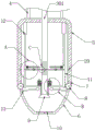
FIG. 2 is a schematic view of the cross-sectional structure of the interior of a forearm of an industrial robot according to the invention;
FIG. 3 is an enlarged schematic view of the structure at A in FIG. 2;
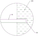
FIG. 4 is an enlarged schematic view of the structure at B in FIG. 2;
fig. 5 is an enlarged schematic view of the structure at C in fig. 2.
In the figure: the device comprises a sliding rail 1, a sliding seat 2, a telescopic cylinder 3, a cylinder arm 301, a cylinder seat 302, a suspender 4, a arm box 5, a protective box plate 6, a rotating groove 7, a gear 8, a rubber sucker 9, a pressure sensor 10, a rack 11, a telescopic sleeve 12, an extrusion rod 13, a first limiting hole 14, a servo motor 15, a screw rod 16, a nut 17, a first connecting rod 18, a second connecting rod 19, a second limiting hole 20, an air outlet pipe 21, a supporting plate 22, an air outlet bag 23, an upper air bag 24, an air outlet pipe 25 and an air suction pipe 26.
Detailed Description
The following description of the embodiments of the present invention will be made clearly and completely with reference to the accompanying drawings, in which it is apparent that the embodiments described are only some embodiments of the present invention, but not all embodiments.
Referring to fig. 2-5, an industrial robot's forearm, including flexible cylinder 3 and arm case 5, wherein flexible cylinder 3 comprises cylinder block 302 and arm 301, arm 301 slides and runs through arm case 5, the rotation groove 7 has all been seted up to the two opposite lateral walls of arm case 5, the rotation inslot 7 internal rotation is connected with gear 8, all fixedly connected with guard box board 6 on the lateral wall of each gear 8, and can seal arm case 5 after two guard box boards 6 close, top fixedly connected with telescopic tube 12 in the arm case 5, and telescopic tube 12's telescopic end fixedly connected with rack 11, rack 11 meshes with gear 8, rack 11 is connected with arm 301 through coupling mechanism, rubber suction cup 9 is installed to the lower extreme of arm 301.
The connecting mechanism comprises a screw 16, a nut 17, a first connecting rod 18 and a second connecting rod 19, wherein the first connecting rod 18 and the second connecting rod 19 are respectively and fixedly connected with two sides of the nut 17, the nut 17 is in threaded connection with the screw 16, the first connecting rod 18 slides through the rack 11, a first limiting hole 14 matched with the first connecting rod 18 is formed in the inner wall of the arm box 5, and a second limiting hole 20 matched with the second connecting rod 19 is formed in the side wall of the cylinder arm 301.
The first link 18 always penetrates the rack 11 during the left-right movement, so that the nut 17 can be limited to move horizontally. Further, the lengths of the first link 18 and the second link 19 can ensure that: at least one of the first connecting rod 18 and the second connecting rod 19 always enters the first limiting hole 14 or the second limiting hole 20, so that when the protective case plate 6 is closed, the first connecting rod 18 and the second connecting rod 19 can fix the position of the rack 11 without moving the rack 11 downwards.
The bottom of the protective box plate 6 is provided with a pressure sensor 10, the side wall of the rack 11 is provided with a servo motor 15, and an output shaft of the servo motor 15 is fixedly connected with a screw 16. It should be noted that, the pressure sensor 10, the servo motor 15 and the telescopic cylinder 3 may be controlled to be started by a controller, and the logic circuit may be specifically designed with reference to the use process of the present invention.
Referring to fig. 5, a support plate 22 is fixedly connected to the side wall of the cylinder arm 301, a lower air bag 23 is fixedly arranged at the lower end of the support plate 22, the lower air bag 23 is communicated with the rubber sucker 9 through an air suction pipe 26, the lower air bag 23 is also communicated with an air outlet pipe 21, check valves are arranged in the air suction pipe 26 and the air outlet pipe 21, and an extrusion rod 13 is fixedly connected to the inner wall of the protective box plate 6. It should be noted that, the check valve in the air suction pipe 26 makes air only flow from the rubber suction cup 9 to the lower air bag 23, and the lower air bag 23 has stronger elasticity, after the lower air bag 23 is extruded by the extrusion rod 13, the lower air bag 23 can bulge by self elasticity, and at this moment, the volume of the lower air bag 23 is increased, a part of air can be sucked from the rubber suction cup 9, and when the rubber suction cup 9 adsorbs a product, the adsorption force of the rubber suction cup 9 can be increased, so that the falling off is effectively prevented. In addition, the one-way valve in the air outlet pipe 21 enables air to flow from the lower air bag 23 to the air outlet pipe 21 only, so that in combination, the lower air bag 23 can only suck air from the air suction pipe 26 and only can exhaust air from the air outlet pipe 21.
Referring to fig. 5, an upper air bag 24 is fixedly connected to the upper end of the support plate 22, the air outlet pipe 21 is communicated with the upper air bag 24, the upper air bag 24 is also communicated with an air outlet pipe 25, a pressure release valve is installed in the air outlet pipe 25, and a pneumatic sounding component is also installed in the air outlet pipe 25. By providing the relief valve, the relief valve may be set to a certain threshold value, and the air flow can be discharged through the exhaust pipe 28 only when the air pressure in the upper air bag 24 increases to the threshold value, so that the air flow at this time has a high flow velocity, and sound can be generated when passing through the pneumatic sound generating component.
The invention also provides an industrial robot, referring to fig. 1, comprising the small arm of the industrial robot, a moving slide rail 1, a slide seat 2 and a boom 4, wherein the slide seat 2 slides along the moving slide rail 1, and the upper end and the lower end of the boom 4 are fixedly connected with the slide seat 2 and an arm box 5 respectively. It should be noted that, the moving slide rail 1 may be an electric slide rail, so that the driving slide carriage 2 can linearly move along the moving slide rail 1, and the parts such as the small arm of the industrial robot below the slide carriage 2 are driven to move together, so as to transport the product to the designated position.
When the invention is used, when the slide carriage 2 drives the lower arm box 5 to move to a designated position along the slide rail 1, and the cylinder arm 301 of the telescopic cylinder 3 drives the rubber suction cup 9 to move downwards, referring to fig. 2, the rack 11 is connected with the cylinder arm 301 through the first connecting rod 18, the nut 17 and the second connecting rod 19 because the second connecting rod 19 is inserted into the second limiting hole 20 at the moment. Therefore, when the cylinder arm 301 drives the rubber suction cup 9 to move downwards, the rack 11 moves downwards, so that the rack 11 can push the gear 8 to rotate outwards and drive the protection box plates 6 at two sides to turn outwards together, and the protection box plates 6 and the extrusion rod 13 can also gradually move away from the rack 11 along with the downward movement of the rack 11, so that the downward movement of the rack 11 and the cylinder arm 301 cannot be blocked (the extrusion rod 13 can be arranged at the front side or the rear side of the rack 11 to avoid the rack 11).
When the protective case plate 6 is completely turned outwards, the cylinder arm 301 drives the rubber suction cup 9 to move out of the arm case 5, and at the moment, the rubber suction cup 9 is positioned on a product and is extruded when the cylinder arm 301 moves downwards, so that air in the rubber suction cup 9 can be discharged, and the rubber suction cup 9 adsorbs the product. Then the cylinder arm 301 drives the rubber sucker 9 and the adsorbed product to move back into the arm box 5, and the rack 11 moves upwards at the moment, so that the gears 8 on two sides rotate inwards and drive the two protection box plates 6 to rotate and be combined together, as shown in the state of fig. 2. The slide 2 can now slide along the slide rail 1 to the destination for transporting the product to the destination.
If the product falls off from the rubber suction disc 9 during transportation, the fallen product falls to the bottoms of the two protection box plates 6, so that the product cannot fall to the ground to generate pollution.
When the product falls on the bottom of the protection box plate 6, the pressure sensor arranged on the bottom of the protection box plate 6 senses the gravity downward pressure of the product, so that a signal can be sent to the servo motor 15, the servo motor 15 drives the screw rod 16 to rotate, at the moment, the nut 17 can move towards the inner wall of the arm box 5, the nut 17 drives the first connecting rod 18 and the second connecting rod 19 on the nut 17 to synchronously move, the second connecting rod 19 gradually breaks away from the second limiting hole 20 and the first connecting rod 18 and gradually enters the first limiting hole 14, and referring to fig. 3, at the moment, the rack 11 is separated from the cylinder arm 301 and is connected with the arm box 5 through the first connecting rod 18, at the moment, the position of the rack 11 still cannot change, the position of the protection box plate 6 can be fixed through the gear 8, and when the cylinder arm 301 moves downward again, the rack 11 cannot be driven to move.
At this time, the telescopic cylinder 3 can be controlled, so that the cylinder arm 301 moves down again, the cylinder arm 301 drives the rubber suction cup 9 to move down again, the rubber suction cup 9 is positioned above the product again and extrudes the internal air, so that the fallen product can be adsorbed again, then the cylinder arm 301 drives the rubber suction cup 9 and the product to move up again and reset, then the controller controls the servo motor 15 again to drive the screw 16 to rotate reversely, the nut 17 drives the first connecting rod 18 and the second connecting rod 19 to move back, the rack 11 is separated from the arm box 5 and is connected with the cylinder arm 301 again, so that when the product is transported to a destination, the cylinder arm 301 drives the rubber suction cup 9 and the product to move out of the arm box 5, the cylinder arm 301 can drive the rack 11 to move down to open the protective box plate 6.
And it should be mentioned that, when the cylinder arm 301 drives the rubber suction cup 9 to move downwards to adsorb the product, because the position of the protection box plate 6 is fixed at this time, the position of the extrusion rod 13 is also unchanged, when the cylinder arm 301 moves downwards, referring to fig. 4, the lower air bag 23 will be extruded by the extrusion rod 13, the air in the lower air bag 23 can be extruded into the upper air bag 24 through the air outlet pipe 21, and when the cylinder arm 301 drives the adsorption product to move upwards, the lower air bag 23 can bulge a part by means of its own elasticity and suck a part of air from the rubber suction cup 9, so that the suction force of the rubber suction cup 9 can be increased, and falling off in the transportation process can be avoided.
Further, if the cylinder arm 301 drives the rubber suction cup 9 to move up and down once and does not adsorb the product, the pressure sensor 10 still receives the pressure of the product, and the controller does not control the servo motor 15 to drive the screw 16 to rotate reversely, and continues to control the cylinder arm 301 to move down and up to drive the rubber suction cup 9 to adsorb the product until the product is adsorbed. When the cylinder arm 301 moves up and down for many times and cannot absorb the product, the lower air bag 23 below the supporting plate 22 also moves down for many times along with the cylinder arm 301 and is extruded by the extrusion rod 13 for many times, and the air in the lower air bag 23 is extruded into the upper air bag 24 continuously, so that the air pressure in the upper air bag 24 also continuously rises, when the air pressure in the upper air bag 24 rises to the threshold value of the pressure release valve in the exhaust pipe 25, the pressure release valve in the exhaust pipe 25 is opened, the air in the upper air bag 24 is rapidly discharged from the exhaust pipe 25, and the air flow can send out alarm sounds through the pneumatic sounding component in the exhaust pipe 25, so that when the cylinder arm 301 drives the rubber sucker 9 to move down for many times and does not absorb the product, workers are informed of the front treatment through the alarm sounds in time.
The foregoing is only a preferred embodiment of the present invention, but the scope of the present invention is not limited thereto, and any person skilled in the art, who is within the scope of the present invention, should make equivalent substitutions or modifications according to the technical scheme of the present invention and the inventive concept thereof, and should be covered by the scope of the present invention.
Claims (6)
1. The utility model provides an industrial robot's forearm, includes flexible cylinder (3) and arm case (5), and wherein flexible cylinder (3) comprises cylinder block (302) and arm (301), a serial communication port, arm (301) slip runs through arm case (5), rotation groove (7) have all been seted up to the opposite side wall of arm case (5), rotation groove (7) internal rotation is connected with gear (8), each equal fixedly connected with guard box board (6) on the lateral wall of gear (8), and two guard box board (6) close arm case (5) after closing, top fixedly connected with telescopic sleeve (12) in arm case (5), just telescopic sleeve's (12) telescopic end fixedly connected with rack (11), rack (11) and gear (8) meshing, rack (11) are connected with arm (301) through coupling mechanism, rubber suction cup (9) are installed to the lower extreme of arm (301).
2. The small arm of an industrial robot according to claim 1, wherein the connecting mechanism comprises a screw rod (16), a nut (17), a first connecting rod (18) and a second connecting rod (19), the first connecting rod (18) and the second connecting rod (19) are fixedly connected with two sides of the nut (17) respectively, the nut (17) is in threaded connection with the screw rod (16), the first connecting rod (18) penetrates through the rack (11) in a sliding manner, a first limiting hole (14) matched with the first connecting rod (18) is formed in the inner wall of the arm box (5), and a second limiting hole (20) matched with the second connecting rod (19) is formed in the side wall of the cylinder arm (301).
3. The forearm of an industrial robot according to claim 2, characterized in that the bottom of the protective box plate (6) is provided with a pressure sensor (10), the side wall of the rack (11) is provided with a servo motor (15), and the output shaft of the servo motor (15) is fixedly connected with a screw (16).
4. The forearm of an industrial robot according to claim 1, wherein the side wall of the cylinder arm (301) is fixedly connected with a supporting plate (22), a lower air bag (23) is fixedly arranged at the lower end of the supporting plate (22), the lower air bag (23) is communicated with a rubber sucker (9) through an air suction pipe (26), the lower air bag (23) is also communicated with an air outlet pipe (21), check valves are arranged in the air suction pipe (26) and the air outlet pipe (21), and an extrusion rod (13) is fixedly connected to the inner wall of the protective box plate (6).
5. The forearm of an industrial robot according to claim 4, wherein the upper end of the supporting plate (22) is fixedly connected with an upper air bag (24), the air outlet pipe (21) is communicated with the upper air bag (24), the upper air bag (24) is further communicated with an air outlet pipe (25), a pressure release valve is installed in the air outlet pipe (25), and a pneumatic sounding component is also installed in the air outlet pipe (25).
6. An industrial robot, characterized by comprising the forearm of an industrial robot according to any one of claims 1-5, further comprising a moving slide rail (1), a slide seat (2) and a boom (4), wherein the slide seat (2) slides along the moving slide rail (1), and the upper end and the lower end of the boom (4) are fixedly connected with the slide seat (2) and the arm box (5) respectively.
Priority Applications (1)
| Application Number | Priority Date | Filing Date | Title |
|---|---|---|---|
| CN202310426523.1A CN116141296B (en) | 2023-04-20 | 2023-04-20 | Industrial robot's forearm and industrial robot |
Applications Claiming Priority (1)
| Application Number | Priority Date | Filing Date | Title |
|---|---|---|---|
| CN202310426523.1A CN116141296B (en) | 2023-04-20 | 2023-04-20 | Industrial robot's forearm and industrial robot |
Publications (2)
| Publication Number | Publication Date |
|---|---|
| CN116141296A true CN116141296A (en) | 2023-05-23 |
| CN116141296B CN116141296B (en) | 2023-07-14 |
Family
ID=86351029
Family Applications (1)
| Application Number | Title | Priority Date | Filing Date |
|---|---|---|---|
| CN202310426523.1A Active CN116141296B (en) | 2023-04-20 | 2023-04-20 | Industrial robot's forearm and industrial robot |
Country Status (1)
| Country | Link |
|---|---|
| CN (1) | CN116141296B (en) |
Citations (9)
| Publication number | Priority date | Publication date | Assignee | Title |
|---|---|---|---|---|
| CN205630624U (en) * | 2016-04-21 | 2016-10-12 | 陈昊 | Full -automatic remote control pendulum goods transport robotic arm |
| CN107471241A (en) * | 2017-09-30 | 2017-12-15 | 苏州科技大学 | Flat plate gripping robot |
| DE102017120409A1 (en) * | 2016-09-20 | 2018-03-22 | Hans-Jürgen Kasprich | Gripper arrangement for detecting pieces of dough or baked goods |
| CN107969221A (en) * | 2018-01-12 | 2018-05-01 | 浙江师范大学 | A kind of full-automatic watermelon picking machine |
| CN108214535A (en) * | 2017-12-29 | 2018-06-29 | 南京理工大学 | A kind of Synchronization Control manipulator |
| CN207549349U (en) * | 2017-11-08 | 2018-06-29 | 广州市金翰机械有限公司 | A kind of injection taking mechanical hand |
| CN108526837A (en) * | 2018-04-13 | 2018-09-14 | 宁波德深机械设备有限公司 | Automatic assembling device people for flow line production |
| CN211253044U (en) * | 2019-10-29 | 2020-08-14 | 深圳市鼎典航模科技有限公司 | A grab thing mechanism for unmanned aerial vehicle snatchs goods |
| CN217458493U (en) * | 2022-08-22 | 2022-09-20 | 河南省豫东起重建筑设备有限公司 | Bridge crane with electromagnetic chuck grab |
-
2023
- 2023-04-20 CN CN202310426523.1A patent/CN116141296B/en active Active
Patent Citations (9)
| Publication number | Priority date | Publication date | Assignee | Title |
|---|---|---|---|---|
| CN205630624U (en) * | 2016-04-21 | 2016-10-12 | 陈昊 | Full -automatic remote control pendulum goods transport robotic arm |
| DE102017120409A1 (en) * | 2016-09-20 | 2018-03-22 | Hans-Jürgen Kasprich | Gripper arrangement for detecting pieces of dough or baked goods |
| CN107471241A (en) * | 2017-09-30 | 2017-12-15 | 苏州科技大学 | Flat plate gripping robot |
| CN207549349U (en) * | 2017-11-08 | 2018-06-29 | 广州市金翰机械有限公司 | A kind of injection taking mechanical hand |
| CN108214535A (en) * | 2017-12-29 | 2018-06-29 | 南京理工大学 | A kind of Synchronization Control manipulator |
| CN107969221A (en) * | 2018-01-12 | 2018-05-01 | 浙江师范大学 | A kind of full-automatic watermelon picking machine |
| CN108526837A (en) * | 2018-04-13 | 2018-09-14 | 宁波德深机械设备有限公司 | Automatic assembling device people for flow line production |
| CN211253044U (en) * | 2019-10-29 | 2020-08-14 | 深圳市鼎典航模科技有限公司 | A grab thing mechanism for unmanned aerial vehicle snatchs goods |
| CN217458493U (en) * | 2022-08-22 | 2022-09-20 | 河南省豫东起重建筑设备有限公司 | Bridge crane with electromagnetic chuck grab |
Also Published As
| Publication number | Publication date |
|---|---|
| CN116141296B (en) | 2023-07-14 |
Similar Documents
| Publication | Publication Date | Title |
|---|---|---|
| CN105540260A (en) | Product adsorption type shifting device | |
| CN205313708U (en) | Go up unloading suction means | |
| CN108526837A (en) | Automatic assembling device people for flow line production | |
| CN116141296B (en) | Industrial robot's forearm and industrial robot | |
| CN112571444A (en) | Mechanical arm vacuum adsorption system and control method thereof | |
| CN113618767A (en) | Industrial robot with flexible machinery snatchs mechanism | |
| CN114620481A (en) | Multi-vehicle-type flexible stepless self-adaptive switching and carrying device and control method thereof | |
| CN112660813A (en) | Electric vacuum chuck at tail end of mechanical arm | |
| CN111470112A (en) | Automatic industrial robot manipulator for vanning | |
| CN209052095U (en) | Glass pick-up component for 3D bend glass processing manipulator | |
| CN216301644U (en) | Food level additive wrapping bag encapsulation fixture | |
| CN111941936B (en) | Bag mouth shaping mechanism | |
| CN113616102B (en) | Anti-falling window cleaning machine | |
| CN104925463B (en) | The strainer of carrier chain in conveying worm | |
| CN209868631U (en) | Anti-skid fixing manipulator of transfer robot | |
| JP2007217006A (en) | Apparatus for inverted extraction and its method | |
| CN216889653U (en) | Sponge suction tool | |
| CN108214683A (en) | A kind of solid wood and plate fitment Digitized manufacturing vacuum chuck device | |
| CN208103418U (en) | A kind of bagged material automatic loading device | |
| CN205204277U (en) | Sucking disc reaches unstacker including it for braided bag | |
| CN211943923U (en) | Pneumatic type anti-turnover adsorption bucket sucking device for grabbing and stacking food | |
| CN208089489U (en) | Vacuum suction apparatus and family's electrolemma cutting machine with it | |
| CN218753599U (en) | Sucking disc and sucking disc device | |
| CN219967642U (en) | Integrated die type multifunctional vacuum suction tool | |
| CN112059570A (en) | Separating device for separating original paper containing smooth area |
Legal Events
| Date | Code | Title | Description |
|---|---|---|---|
| PB01 | Publication | ||
| PB01 | Publication | ||
| SE01 | Entry into force of request for substantive examination | ||
| SE01 | Entry into force of request for substantive examination | ||
| GR01 | Patent grant | ||
| GR01 | Patent grant |