CN115788399A - Device and method for measuring oil-water relative permeability curve of high-multiple water-flooding core - Google Patents
Device and method for measuring oil-water relative permeability curve of high-multiple water-flooding core Download PDFInfo
- Publication number
- CN115788399A CN115788399A CN202211382197.0A CN202211382197A CN115788399A CN 115788399 A CN115788399 A CN 115788399A CN 202211382197 A CN202211382197 A CN 202211382197A CN 115788399 A CN115788399 A CN 115788399A
- Authority
- CN
- China
- Prior art keywords
- water
- oil
- relative permeability
- core
- precision
- Prior art date
- Legal status (The legal status is an assumption and is not a legal conclusion. Google has not performed a legal analysis and makes no representation as to the accuracy of the status listed.)
- Granted
Links
- XLYOFNOQVPJJNP-UHFFFAOYSA-N water Substances O XLYOFNOQVPJJNP-UHFFFAOYSA-N 0.000 title claims abstract description 123
- 230000035699 permeability Effects 0.000 title claims abstract description 69
- 238000000034 method Methods 0.000 title claims abstract description 46
- 238000006073 displacement reaction Methods 0.000 claims abstract description 46
- 239000007788 liquid Substances 0.000 claims abstract description 35
- 238000000926 separation method Methods 0.000 claims abstract description 20
- 238000005259 measurement Methods 0.000 claims abstract description 7
- 239000011435 rock Substances 0.000 claims description 31
- XEEYBQQBJWHFJM-UHFFFAOYSA-N Iron Chemical compound [Fe] XEEYBQQBJWHFJM-UHFFFAOYSA-N 0.000 claims description 12
- 229920001971 elastomer Polymers 0.000 claims description 6
- 229910052742 iron Inorganic materials 0.000 claims description 6
- 238000005303 weighing Methods 0.000 claims description 5
- 230000008569 process Effects 0.000 abstract description 14
- 230000008859 change Effects 0.000 abstract description 8
- 238000011160 research Methods 0.000 abstract description 3
- 238000004088 simulation Methods 0.000 abstract description 3
- 230000002706 hydrostatic effect Effects 0.000 abstract description 2
- 239000012071 phase Substances 0.000 description 23
- 239000008398 formation water Substances 0.000 description 14
- 238000004519 manufacturing process Methods 0.000 description 13
- 239000000243 solution Substances 0.000 description 9
- 239000011148 porous material Substances 0.000 description 7
- 229920006395 saturated elastomer Polymers 0.000 description 6
- 230000015572 biosynthetic process Effects 0.000 description 4
- 230000001186 cumulative effect Effects 0.000 description 4
- 230000009471 action Effects 0.000 description 3
- 230000032683 aging Effects 0.000 description 2
- 238000011161 development Methods 0.000 description 2
- 230000018109 developmental process Effects 0.000 description 2
- 238000010586 diagram Methods 0.000 description 2
- 238000001914 filtration Methods 0.000 description 2
- 239000012530 fluid Substances 0.000 description 2
- 238000013148 permeation assay Methods 0.000 description 2
- 208000035126 Facies Diseases 0.000 description 1
- 239000008346 aqueous phase Substances 0.000 description 1
- 230000009286 beneficial effect Effects 0.000 description 1
- 238000004364 calculation method Methods 0.000 description 1
- 238000006243 chemical reaction Methods 0.000 description 1
- 150000001875 compounds Chemical class 0.000 description 1
- 238000007796 conventional method Methods 0.000 description 1
- 230000008570 general process Effects 0.000 description 1
- 230000008595 infiltration Effects 0.000 description 1
- 238000001764 infiltration Methods 0.000 description 1
- 238000002347 injection Methods 0.000 description 1
- 239000007924 injection Substances 0.000 description 1
- 230000003993 interaction Effects 0.000 description 1
- 238000012417 linear regression Methods 0.000 description 1
- 239000000203 mixture Substances 0.000 description 1
- 230000000704 physical effect Effects 0.000 description 1
- 238000011084 recovery Methods 0.000 description 1
- 238000009738 saturating Methods 0.000 description 1
- 238000012360 testing method Methods 0.000 description 1
Images


Abstract
The invention discloses a device and a method for measuring a high-multiple water-drive core oil-water relative permeability curve, wherein the device is characterized in that an oil-water separator, a high-precision measuring tube and a hose are connected in series to form a communicating vessel based on the hydrostatic principle, and the communicating vessel and a fixing device form a high-multiple water-drive oil-water separation high-precision continuous measuring unit, wherein the oil-water separator is arranged on the high-precision measuring tube, and the height of the liquid level in the communicating vessel is controlled by adjusting the height of the hose, so that the automatic separation, the precision and the continuous measurement of oil and water are realized; the method is characterized in that a high-multiple water-drive oil-water separation high-precision continuous metering unit is used for measuring the change of the permeability end value under different displacement multiples, so that the high-multiple water-drive core oil-water relative permeability curve is obtained through interpolation, the operation is simple, the representation of the middle process is more accurate, and the method is expected to be applied to the oil reservoir numerical simulation research considering the phase permeability time change.
Description
Technical Field
The invention belongs to the technical field of oil and gas reservoir development, and relates to a device and a method for measuring a high-multiple water-drive core oil-water relative permeability curve.
Background
The oil-water relative permeability is a dynamic parameter for the interaction of reaction rocks with oil and water, and is also the most important parameter in oil reservoir engineering. The unsteady state method occupies the mainstream position in the measurement of the relative permeability curve by virtue of the characteristics of rapidness and accuracy, and the JBN method is the most commonly used method. The general process is as follows: the method comprises the steps of performing a constant pressure difference or constant speed oil displacement test on an oil reservoir rock sample, recording the output of each fluid and the change of the pressure difference at two ends of the rock sample along with time at the outlet end of the rock sample, calculating by using a J.B.N. method to obtain the relative permeability of oil and water, and drawing a relation curve between the relative permeability of oil and water and the water saturation.
After decades of water injection development, most of oil fields in China enter the later period of high water content, the change rule of the physical property of a reservoir, particularly the relative permeability, is clear, and the method is of great importance for improving the recovery ratio. However, the conventional relative permeability measuring device and method cannot realize automatic separation and accurate and continuous metering of oil and water in the high-multiple water flooding process.
According to a standard 'relative permeability determination method of two-phase fluid in rock' (GB/T28912-2012) implemented in 2013, the lower end of an oil-water separator needs to open a valve at regular time to discharge water in the measurement process, so that continuous metering cannot be realized, and the method is not suitable for measuring a relative permeability curve with a displacement multiple of more than 30 PV. Meanwhile, the oil-water separator commonly used in the market does not have a metering function, an oil phase needs to be transferred into an independent metering pipe, the operation is complex, and the error is large. In addition, the part has the device of oil-water separation and measurement function concurrently, and its precision is difficult to the little change of the high multiple water flooding core facies infiltration endpoint value of sign.
Therefore, it is necessary to develop a device and a method suitable for measuring the oil-water relative permeability curve of the high-multiple water-drive core, and solve the problem that the change of the high-multiple water-drive core relative permeability end point value is difficult to characterize.
Disclosure of Invention
The invention aims to: the device and the method are suitable for measuring the oil-water relative permeability curve of the high-multiple water-drive rock core, the difficulty that automatic oil-water separation, accuracy and continuous metering cannot be simultaneously realized in the traditional oil-water relative permeability measuring process is overcome, the problem that the measuring accuracy of the seepage end point value of the high-multiple water-drive rock core is not high under different displacement multiples is solved, the operation is simple, the representation of the intermediate process is more accurate, and the device and the method are expected to be applied to simulation research of the variable value during phase seepage.
The technical scheme adopted by the invention is as follows:
the device comprises an ISCO pump, a six-way valve I, an intermediate container, a six-way valve II, a core holder and a high-multiple water-drive oil-water separation high-precision continuous metering unit which are sequentially connected;
as a further limitation of the above technical scheme, the middle part of the core holder is connected with a pressure sensor and a hand pump through pipelines; two ends of the rock core holder are connected with pressure sensors through pipelines;
as a further limitation of the above technical solution, the high-multiple water-drive oil-water separation high-precision continuous metering unit comprises a communicating vessel and a fixing device, wherein the left end of the continuous metering unit is provided with a digital camera and a computer, the digital camera is used for taking a picture and recording the picture, and the computer can automatically store the picture; a beaker, a balance and a computer are arranged at the right end of the device, the beaker is used for collecting the liquid discharged from the communicating vessel, the balance is used for weighing the liquid in the beaker in real time, and the computer is used for recording weight data;
as a further limitation of the technical scheme, the communicating vessel consists of an oil-water separator, an adapter I, a high-precision metering tube, an adapter II and a hose; the upper end of the oil-water separator is provided with an opening, the liquid outlet end of the displacement device is inserted from the upper end of the oil-water separator and is arranged at the bottom of the oil-water separator, the lower end of the displacement device is connected with the high-precision metering tube through an adapter I, and the lower end of the high-precision metering tube is connected with the hose through an adapter II;
as a further limitation of the above technical solution, the fixing device is composed of a universal clamp, an iron stand, a cross clamp and a rubber band, the universal clamp is used for fixing the high-precision measuring tube, the iron stand is used for supporting the communicating vessel, the cross clamp is used for adjusting the liquid level height in the communicating vessel, and the rubber band is used for fixing the hose;
the invention also provides a method for measuring the oil-water relative permeability curve of the high-multiple water-drive core, which comprises the following steps:
s1, preparing simulated oil and simulated formation water, measuring viscosity and density, and respectively recording as mu o 、μ w 、ρ o 、ρ w Respectively filtering, vacuumizing and then filling the mixture into an intermediate container; measuring core length, diameter and mass, respectivelyIs marked as L, D, m 0 (ii) a Vacuumizing the core, performing saturation treatment on the core by using simulated formation water, weighing after saturation, and recording the mass as m 1 Calculating the cross-sectional area A and the pore volume V p Porosity, degree of porosity
S3, filling the saturated rock core into a rock core holder, connecting a displacement process, displacing the rock core saturated with simulated formation water to a water-bound state by utilizing simulated formation oil, displacing the rock core by utilizing the simulated formation oil until water is no longer produced at an outlet and the oil production speed is stable, and recording the cumulative water production volume V of the outlet at the moment wc Displacement speed Q, displacement differential pressure Δ p c Finally, the saturation S in the state of bound water is obtained wc And oil phase permeability k o ;
S4, placing the core in a core holder and aging for not less than 2 days; the phase permeation assay was performed using an unsteady state method: and (4) displacing the rock core with simulated formation water at a displacement speed Q. Recording water breakthrough time T and cumulative oil yield V at water breakthrough time O Liquid production amount Q o And the displacement pressure difference deltap across the core o (ii) a At the initial stage of water breakthrough, recording in an encrypted manner, gradually increasing the recorded time interval along with the continuous decrease of the oil output, and measuring the water phase permeability under the residual oil after the water content reaches 99.9%;
s5, continuously measuring the accumulated oil yield V (t), the accumulated liquid yield Q (t) and the displacement differential pressure delta p (t) at two ends of the rock core under different displacement multiples by using a high-precision measuring tube;
s6, carrying out interpolation by utilizing the residual oil saturation and the water phase relative permeability under different displacement multiples to obtain a relative permeability curve under the corresponding displacement multiple.
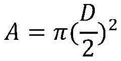
As a further limitation of the above technical solution, in step S2, the cross-sectional area of the core, the volume of the pores, and the porosity are calculated according to the following formulas:
V b =LA


wherein D is the measured core diameter, cm; l is the measured core length, cm; m is 0 Measured core dry weight, g; m is a unit of 1 Simulating the wet weight g of formation water for the measured core saturation; ρ is a unit of a gradient w To simulate the density of formation water, g/cm 3 。
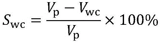
As a further limitation of the above technical solution, in step S3, the irreducible water saturation and the permeability calculation formula under the irreducible water saturation are as follows:

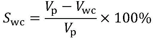
in the formula: k o (S wi ) To the oil phase permeability in the bound water state, mD; q is the flow rate of oil, mL/s; mu.s o To determine the oil viscosity at temperature, mPa · s; l is the core length, cm; a is the sectional area of the core in cm 2 ;Δp c The core displacement differential pressure is MPa.
As a further limitation of the above technical solution, in step S4, the displacement speed is determined by the following formula:
Lμ o v w ≥1
as a further limitation of the above technical solution, in step S4, the relative permeability of oil and water is calculated by the following formula:
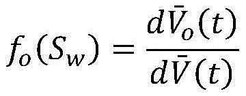


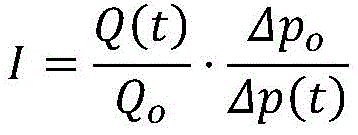
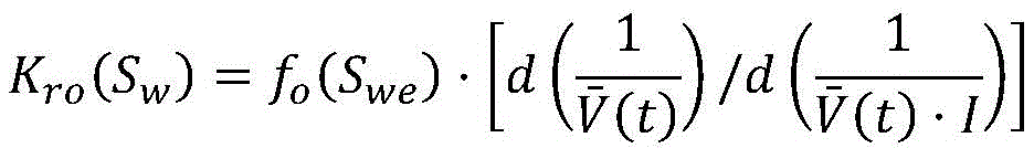
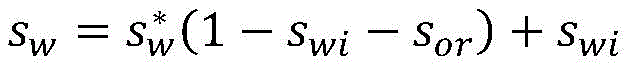
in the formula: k ro (S w ) The relative permeability of the oil phase under the saturation degree of the produced liquid is dimensionless; k is rw (S w ) The relative permeability of the water phase under the saturation degree of the produced liquid is dimensionless; the displacement pore volume is accumulated and is dimensionless;
 the pore volume multiple is accumulated without dimension; f. of o (S w ) The oil content (the ratio of the oil production to the total liquid production) of the produced liquid is dimensionless; s. the we ,S wi The produced liquid water saturation and the rock core bound water saturation are respectively dimensionless; i is the ratio of the flow capacity at any moment to the flow capacity at the initial moment; q (t) is the liquid volume taken at time t, cm 3 /s;Q o The amount of liquid taken at the initial time (water breakthrough time), cm 3 S; delta p (t) is the pressure difference between two ends of the rock core at the time t, and is MPa; Δ p o The pressure difference between two ends of the rock core at the initial time (water breakthrough time) is MPa.
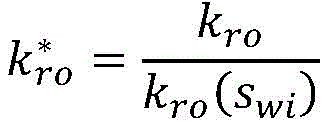
As a further limitation of the above technical solution, the relative permeability of oil and water is normalized by the following formula:


wherein:


in the formula (I), the compound is shown in the specification, the method is a standardized water phase saturation value and is dimensionless;
 the relative permeability of the oil phase is standardized and is dimensionless;
 the water relative permeability is standardized and is dimensionless; a. b is fitting parameter without dimension.
Compared with the prior art, the invention has the following beneficial effects:
a high-multiple water-drive core oil-water relative permeability curve measuring device and method are provided, a high-multiple water-drive oil-water separation high-precision continuous metering unit is designed based on the hydrostatic principle, and the device is applied to measure the change of the permeability end point value under different displacement multiples, so that the oil-water relative permeability curve of the high-multiple water-drive core under different displacement multiples is obtained through interpolation.
Compared with the conventional relative permeability measuring device, the device is additionally provided with the digital camera, the computer and the communicating vessel, and has the characteristics of simple operation, convenient recording and continuous metering; compared with the oil-water separator commonly used in the market, the device has the functions of automatic oil-water separation and accurate metering; compared with a device with oil-water separation and metering functions, the device has higher precision which reaches 0.01mL.
Compared with the conventional method for measuring a plurality of relative permeability curves, the method has the advantages that only one relative permeability curve is measured, the change of the permeability end point value of the water-flooding core under different displacement multiples is continuously measured, the relative permeability curves under different displacement multiples are obtained through interpolation, the operation is simple, the time and the labor are saved, and the representation of the middle process is more accurate.
The device and the method overcome the difficulty that automatic separation, accuracy and continuous metering of oil and water cannot be realized simultaneously in the traditional oil-water relative permeability measuring process, solve the problem that the measurement accuracy of the seepage endpoint value of the high-multiple water-drive rock core is not high under different displacement multiples, have simple operation and more accurate representation of the intermediate process, and are expected to be applied to simulation research of the phase seepage time variable value.
Drawings
In order to more clearly illustrate the technical solutions of the embodiments of the present invention, the drawings that are required to be used in the embodiments will be briefly described below, it should be understood that the following drawings only illustrate some embodiments of the present invention and therefore should not be considered as limiting the scope, and that for those skilled in the art, other relevant drawings can be obtained according to the drawings without inventive effort, wherein:
FIG. 1 is a schematic diagram of a high-multiple water-flooding core oil-water relative permeability measuring device;
FIG. 2 is a schematic structural diagram of a high-precision continuous metering device for high-multiple water-flooding oil-water separation;
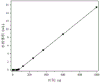
FIG. 3 is a graph of the volume of the oil phase as a function of time for a first embodiment of the present invention;
FIG. 4 is a graph of the aqueous phase volume as a function of time for example one of the present inventions;
FIG. 5 is a graph of normalized oil-water relative permeability according to a first embodiment of the present invention;
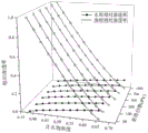
fig. 6 is a graph of oil-water relative permeability under different displacement multiples according to the first embodiment of the present invention.
Detailed Description
In order to make the objects, technical solutions and advantages of the present invention more apparent, the present invention is described in further detail below with reference to the accompanying drawings and embodiments. It should be understood that the detailed description and specific examples, while indicating the preferred embodiment of the invention, are intended for purposes of illustration only and are not intended to limit the scope of the invention. The components of embodiments of the present invention generally described herein and illustrated in the figures may be arranged and designed in a wide variety of different configurations.
Thus, the following detailed description of the embodiments of the present invention, presented in the figures, is not intended to limit the scope of the invention, as claimed, but is merely representative of selected embodiments of the invention. All other embodiments, which can be derived by a person skilled in the art from the embodiments of the present invention without making any creative effort, shall fall within the protection scope of the present invention.
It is noted that relational terms such as "first" and "second," and the like, may be used solely to distinguish one entity or action from another entity or action without necessarily requiring or implying any actual such relationship or order between such entities or actions. Also, the terms "comprises," "comprising," or any other variation thereof, are intended to cover a non-exclusive inclusion, such that a process, method, article, or apparatus that comprises a list of elements does not include only those elements but may include other elements not expressly listed or inherent to such process, method, article, or apparatus. Without further limitation, an element defined by the phrases "comprising a," "8230," "8230," or "comprising" does not exclude the presence of additional like elements in a process, method, article, or apparatus that comprises the element.
In the following specific embodiments, the high-multiple water-drive core oil-water relative permeability curve measuring device is characterized by comprising an ISCO pump (1), a six-way valve I (2), intermediate containers (3, 4), a six-way valve II (5), a core holder (7) and a high-multiple water-drive oil-water separation high-precision continuous metering unit which are sequentially connected as shown in FIGS. 1 and 2; the middle part of the core holder (7) is connected with a pressure sensor (8) and a hand pump (9) through pipelines; two ends of the core holder (7) are connected with pressure sensors (6, 10) through pipelines;
furthermore, the high-precision continuous metering unit for high-multiple water-drive oil-water separation comprises a communicating vessel (12) and a fixing device, wherein a digital camera (20) and a computer (19) are arranged at the left end of the high-precision continuous metering unit, the digital camera is used for photographing and recording, and the computer (20) can automatically store photos; a beaker (17), a balance (18) and a computer (19) are arranged at the right end of the device, the beaker (17) is used for collecting the liquid discharged from the communicating vessel, the balance (18) is used for weighing the liquid in the beaker in real time, and the computer (19) is used for recording weight data;
furthermore, the communicating vessel (12) is composed of an oil-water separator (121), an adapter I (122), a high-precision metering tube (123), an adapter II (124) and a hose (125); the upper end of the oil-water separator (121) is provided with an opening, the liquid outlet end of the displacement device is inserted from the upper end of the oil-water separator (121) and is arranged at the bottom of the oil-water separator, the lower end of the displacement device is connected with the high-precision metering tube (123) through an adapter I (122), and the lower end of the high-precision metering tube is connected with the hose (125) through an adapter II (124);
furthermore, the fixing device is composed of a universal clamp (13), an iron stand (14), a cross clamp (15) and a rubber band (16), wherein the universal clamp (13) is used for fixing the high-precision measuring tube (123), the iron stand (14) is used for supporting the communicating vessel (12), the cross clamp (15) is used for adjusting the liquid level height in the communicating vessel, and the rubber band (16) is used for fixing the hose (125);
example 1
The method for measuring the oil-water relative permeability curve of the high-multiple water-flooding core comprises the following steps:
s1, preparing simulated oil and simulated formation water, measuring the viscosities of the simulated oil and the simulated formation water respectively to be 1mpa · S and 9.31mpa · S by using a rotational viscometer, and measuring the densities of the simulated oil and the simulated formation water respectively to be 0.826g/cm by using a pycnometer 3 、1.007g/cm 3 And is combined withRespectively filtering, vacuumizing and then filling into an intermediate container; measuring the length, the diameter and the mass of the core, wherein the length, the diameter and the mass are respectively 5.001cm, 2.515cm and 52.1913g; vacuumizing the core, saturating the core by using simulated formation water, weighing the saturated core until the mass is 56.2218g, and calculating according to the following formula to obtain the cross-sectional area of 4.98cm 2 Core volume 24.84cm 3 Pore volume 4.51cm 3 Porosity 0.181;

V b =LA


wherein D is the measured core diameter in cm; l is the measured core length, cm; m is 0 Measured core dry weight, g; m is 1 Measuring the wet weight g of the rock core when the rock core is saturated with simulated formation water; rho w To simulate the density of formation water, g/cm 3 。
S2, filling the saturated rock core into a rock core holder, connecting a displacement process, displacing the rock core saturated with simulated formation water to a water-bound state by utilizing simulated formation oil, displacing the rock core by utilizing the simulated formation oil, recording the accumulated water production volume of 2.85mL of the outlet at the moment, the displacement speed of 1mL/min and the displacement pressure difference of 0.043MPa after the outlet does not produce water any more and the oil production speed is stable, and finally obtaining the saturation of 0.3648 and the oil phase permeability of 239mD in the water-bound state;
the irreducible water saturation and the permeability under irreducible water saturation are calculated by the following formula:

in the formula: k o (S wi ) To the oil phase permeability in the bound water state, mD; q is the flow rate of oil, mL/s; mu.s o For determining the oil viscosity at temperature, mPas; l is the core length in cm; a is core sectional area, cm 2 ;Δp c The core displacement differential pressure is MPa.
S3: placing the core in a core holder and aging for not less than 2 days; the phase permeation assay was performed using an unsteady state method: and (3) displacing the rock core by using simulated formation water at a displacement speed of 1mL/min. Recording water breakthrough time 54s, cumulative oil production 0.9mL at the water breakthrough time, cumulative liquid production 0.9mL and displacement differential pressure 0.082MPa at two ends of the rock core; at the initial stage of water breakthrough, recording in an encrypted manner, gradually increasing the recorded time interval along with the continuous decrease of the oil output, and measuring the water phase permeability of the residual oil after the water content reaches 99.9%;
the measured and recorded data are processed according to the following formula to obtain an oil-water relative permeability curve:


in the formula: k ro (S w ) The relative permeability of the oil phase under the saturation degree of the produced liquid is dimensionless; k is rw (S w ) Is the relative permeability of the water phase under the saturation degree of the produced liquid, and is dimensionless; the displacement pore volume is accumulated and is dimensionless;
 the pore volume multiple is accumulated and is dimensionless; f. of o (S w ) The oil content (the ratio of the oil production to the total liquid production) of the produced liquid is dimensionless; s. the we ,S wi The produced liquid water saturation and the rock core bound water saturation are respectively dimensionless; i is the ratio of the flow capacity at any moment to the flow capacity at the initial moment; q (t) is the liquid volume taken at time t, cm 3 /s;Q o The amount of liquid taken out is cm at the initial time (water breakthrough time) 3 S; delta p (t) is the pressure difference between two ends of the rock core at the time t, and is MPa; Δ p of o The pressure difference between two ends of the rock core at the initial time (water breakthrough time) is MPa.
The oil-water relative permeability data were normalized by the following formula:


wherein:


to facilitate fitting, taking the natural logarithm on both sides of the above equation, one can obtain:


the values of a and b are respectively 0.7642 and 1.2286 through linear regression, and then different normalized water phase saturation values are given Calculating the corresponding normalized oil phase relative permeability from the above formula
 Relative permeability of water
 This was then carried back to give the normalized oil-water relative permeability data shown in FIG. 5:


s4: continuously measuring the oil production amount V (t) at the time of 30PV, 100PV, 300PV, 500PV, 700PV and 1000PV, the oil production amount Q (t) and the displacement pressure difference delta p (t) at two ends of the core by using a high-precision measuring tube with the division value of 0.01mL, and shown in FIGS. 3 and 4;
s5: and (3) carrying out phase permeation endpoint interpolation by using data points in the high-multiple water flooding process, and obtaining a relative permeability curve of the water flooding core under different displacement multiples as shown in figure 6.
Claims (6)
1. The high-multiple water-drive core oil-water relative permeability curve measuring device is characterized by comprising an ISCO pump (1), a six-way valve I (2), intermediate containers (3 and 4), a six-way valve II (5), a core holder (7) and a high-multiple water-drive oil-water separation high-precision continuous metering unit which are sequentially connected; the middle part of the core holder (7) is connected with a pressure sensor (8) and a hand pump (9) through pipelines; and two ends of the rock core holder (7) are connected with pressure sensors (6, 10) through pipelines.
2. The device for measuring the oil-water relative permeability curve of the high-multiple water-flooding core according to claim 1, wherein the high-multiple water-flooding oil-water separation high-precision continuous metering unit comprises a communicating vessel (12) and a fixing device, a digital camera (20) and a computer (19) are arranged at the left end of the high-multiple water-flooding oil-water separation high-precision continuous metering unit, the digital camera (20) is used for photographing and recording, and the computer (20) is used for storing photos; the right end of the device is provided with a beaker (17), a balance (18) and a computer (19), the beaker (17) is used for collecting liquid discharged from the communicating vessel, the balance (18) is used for weighing the liquid in the beaker in real time, and the computer (19) is used for recording weight data.
3. The high-multiple water-drive oil-water separation high-precision continuous metering unit as claimed in claim 2, wherein the communicating vessel (12) is composed of an oil-water separator (121), an adapter I (122), a high-precision metering tube (123), an adapter II (124) and a hose (125); the upper end of the oil-water separator (121) is provided with an opening, the liquid outlet end of the displacement device is inserted from the upper end of the oil-water separator (121) and is arranged at the bottom of the oil-water separator, the lower end of the displacement device is connected with the high-precision metering tube (123) through the adapter I (122), and the lower end of the high-precision metering tube is connected with the hose (125) through the adapter II (124).
4. The high-precision continuous metering unit for high-multiple water drive oil-water separation is characterized in that the fixing device is composed of a universal clamp (13), an iron stand (14), a cross clamp (15) and a rubber band (16), the universal clamp (13) is used for fixing the high-precision metering tube (123), the iron stand (14) is used for supporting the communicating vessel (12), the cross clamp (15) is used for controlling the liquid level in the communicating vessel, and the rubber band (16) is used for fixing the hose (125).
5. The method for measuring the oil-water relative permeability curve of the high-multiple water-flooding core is characterized by comprising the following steps of:
s1, measuring a conventional oil-water relative permeability curve of a rock sample by using an unsteady state method;
s2, after the conventional oil-water relative permeability curve measurement is finished, replacing the device by a high-multiple water-drive core oil-water relative permeability curve measurement device to continue displacement, and measuring the residual oil saturation and the water phase relative permeability under different displacement multiples (> 30 PV);
and S3, interpolating through the measured residual oil saturation and water phase relative permeability data, and calculating to obtain an oil-water relative permeability curve of the high-multiple water-flooding core under different displacement multiples.
6. The method for measuring the oil-water relative permeability curve of the high-multiple water-flooding core according to claim 5, wherein the replacing device is a high-multiple water-flooding core oil-water relative permeability curve device for continuous displacement, and comprises the following operations:
s21, before displacement, the height of the hose is controlled by adjusting the cross clamp, so that the liquid level of the communicating vessel exceeds the liquid outlet end of the displacement device;
s22, starting displacement, judging the displacement multiple through the quality of liquid in the beaker, stopping the displacement at a node needing to be measured, controlling the cross clamp to adjust the height of the hose, enabling the liquid level to fall into a readable interval of the high-precision measuring tube, taking a picture by using the digital camera and uploading the picture to the computer, and then adjusting the height of the hose again to enable the liquid level to return to the oil-water separator;
and S23, continuing to displace, and repeating the operation until the next time node needing to be measured.
Priority Applications (1)
| Application Number | Priority Date | Filing Date | Title |
|---|---|---|---|
| CN202211382197.0A CN115788399B (en) | 2022-11-07 | 2022-11-07 | High-multiple water-drive rock core oil-water relative permeability curve measuring device and method |
Applications Claiming Priority (1)
| Application Number | Priority Date | Filing Date | Title |
|---|---|---|---|
| CN202211382197.0A CN115788399B (en) | 2022-11-07 | 2022-11-07 | High-multiple water-drive rock core oil-water relative permeability curve measuring device and method |
Publications (2)
| Publication Number | Publication Date |
|---|---|
| CN115788399A true CN115788399A (en) | 2023-03-14 |
| CN115788399B CN115788399B (en) | 2024-02-09 |
Family
ID=85435769
Family Applications (1)
| Application Number | Title | Priority Date | Filing Date |
|---|---|---|---|
| CN202211382197.0A Active CN115788399B (en) | 2022-11-07 | 2022-11-07 | High-multiple water-drive rock core oil-water relative permeability curve measuring device and method |
Country Status (1)
| Country | Link |
|---|---|
| CN (1) | CN115788399B (en) |
Cited By (1)
| Publication number | Priority date | Publication date | Assignee | Title |
|---|---|---|---|---|
| CN116201538A (en) * | 2023-03-15 | 2023-06-02 | 西南石油大学 | Full life cycle reservoir damage evaluation method based on production degree |
Citations (9)
| Publication number | Priority date | Publication date | Assignee | Title |
|---|---|---|---|---|
| CN2697602Y (en) * | 2004-04-26 | 2005-05-04 | 大庆油田有限责任公司 | Micro-quantity metering device for high water containing and low oil production |
| CN103573234A (en) * | 2012-08-06 | 2014-02-12 | 中国石油化工股份有限公司 | Method for determining complete oil and water relative permeability curve |
| CN204267017U (en) * | 2014-11-03 | 2015-04-15 | 中国石油大学(北京) | A kind of oil-water separation metering device |
| CN107727553A (en) * | 2017-10-31 | 2018-02-23 | 中国石油大学(北京) | A kind of viscous crude free-boundary problem and percolation law measurement apparatus and method |
| CN110160932A (en) * | 2019-06-03 | 2019-08-23 | 西南石油大学 | A kind of oil-water relative permeability curve test device and test method |
| CN110307880A (en) * | 2018-03-27 | 2019-10-08 | 中国石油化工股份有限公司 | Metering device and metering method suitable for High water cut experiment |
| CN213517134U (en) * | 2020-12-10 | 2021-06-22 | 西南石油大学 | Rock core displacement experimental apparatus |
| CN113431537A (en) * | 2021-06-30 | 2021-09-24 | 延安大学 | Unsteady state variable flow rate large-scale core water-flooding gas phase-to-permeability testing method |
| CN113933478A (en) * | 2020-07-13 | 2022-01-14 | 中国石油化工股份有限公司 | High-temperature high-pressure visual oil-water metering device and method |
-
2022
- 2022-11-07 CN CN202211382197.0A patent/CN115788399B/en active Active
Patent Citations (9)
| Publication number | Priority date | Publication date | Assignee | Title |
|---|---|---|---|---|
| CN2697602Y (en) * | 2004-04-26 | 2005-05-04 | 大庆油田有限责任公司 | Micro-quantity metering device for high water containing and low oil production |
| CN103573234A (en) * | 2012-08-06 | 2014-02-12 | 中国石油化工股份有限公司 | Method for determining complete oil and water relative permeability curve |
| CN204267017U (en) * | 2014-11-03 | 2015-04-15 | 中国石油大学(北京) | A kind of oil-water separation metering device |
| CN107727553A (en) * | 2017-10-31 | 2018-02-23 | 中国石油大学(北京) | A kind of viscous crude free-boundary problem and percolation law measurement apparatus and method |
| CN110307880A (en) * | 2018-03-27 | 2019-10-08 | 中国石油化工股份有限公司 | Metering device and metering method suitable for High water cut experiment |
| CN110160932A (en) * | 2019-06-03 | 2019-08-23 | 西南石油大学 | A kind of oil-water relative permeability curve test device and test method |
| CN113933478A (en) * | 2020-07-13 | 2022-01-14 | 中国石油化工股份有限公司 | High-temperature high-pressure visual oil-water metering device and method |
| CN213517134U (en) * | 2020-12-10 | 2021-06-22 | 西南石油大学 | Rock core displacement experimental apparatus |
| CN113431537A (en) * | 2021-06-30 | 2021-09-24 | 延安大学 | Unsteady state variable flow rate large-scale core water-flooding gas phase-to-permeability testing method |
Non-Patent Citations (9)
| Title |
|---|
| 于洪敏;王友启;聂俊;吕成远;崔文富;张莉;: "高注水倍数相对渗透率曲线校正方法研究及应用", 石油钻探技术, no. 04, 19 July 2018 (2018-07-19) * |
| 王曙光, 赵国忠, 余碧君: "大庆油田油水相对渗透率统计规律及其应用", 石油学报, no. 03, 25 May 2005 (2005-05-25) * |
| 王林明;: "低渗油藏渗流机理研究", 胜利油田职工大学学报, no. 03, 15 June 2009 (2009-06-15) * |
| 王树涛;: "强底水油藏水驱倍数定量表征及大幅提液研究", 新疆石油天然气, no. 02, 15 June 2020 (2020-06-15) * |
| 贾虎;邓力珲;: "基于流线聚类人工智能方法的水驱油藏流场识别", 石油勘探与开发, no. 02, 15 January 2018 (2018-01-15) * |
| 赵明月: "强边底水油藏高倍数水驱的数值模拟方法实现及应用", 《中国优秀硕士学位论文全文数据库工程科技I辑》, no. 4, pages 16 - 30 * |
| 郭文敏;李治平;吕道平;贾国澜;寇根;: "基于一维岩心实验参数的三维油藏采收率预测方法及应用", 油气地质与采收率, no. 06, 25 November 2014 (2014-11-25) * |
| 韩洁;宋新民;李军;鞠斌山;李华君;: "扶余油田水驱开发储层参数变化实验研究", 科学技术与工程, no. 14, 18 May 2013 (2013-05-18) * |
| 黄向东, 伊向艺, 赵之波, 朱金堂: "两种油水自动计量方法研究及其装置的实现", 石油仪器, no. 04 * |
Cited By (2)
| Publication number | Priority date | Publication date | Assignee | Title |
|---|---|---|---|---|
| CN116201538A (en) * | 2023-03-15 | 2023-06-02 | 西南石油大学 | Full life cycle reservoir damage evaluation method based on production degree |
| CN116201538B (en) * | 2023-03-15 | 2023-09-12 | 西南石油大学 | Full life cycle reservoir damage evaluation method based on production degree |
Also Published As
| Publication number | Publication date |
|---|---|
| CN115788399B (en) | 2024-02-09 |
Similar Documents
| Publication | Publication Date | Title |
|---|---|---|
| Corey | Measurement of water and air permeability in unsaturated soil | |
| Richards et al. | Influence of capillary conductivity and depth of wetting on moisture retention in soil | |
| Jones | A rapid accurate unsteady-state Klinkenberg permeameter | |
| CN208171813U (en) | A kind of multi-functional permeability test device | |
| CN210264648U (en) | Multifunctional rock core displacement device | |
| CN104237099B (en) | Measure the device and method of compact rock core radial penetration rate | |
| CN109883894A (en) | A kind of superhigh temperature super-pressure stable state air water mutually seeps test device and test method | |
| CN112986097B (en) | Experimental measurement method for determining relative permeability curve of tight reservoir steady state method | |
| JP3381991B2 (en) | Water permeability measuring apparatus and water permeability measuring method using the same | |
| CN107525746A (en) | A kind of method and device for characterizing compact oil reservoir Non-Darcy Flow in Low Permeability Reservoir feature | |
| CN105606787B (en) | Rock core capillary pressure curve test device and method | |
| CN113431537B (en) | Unsteady variable-flow-rate large-scale rock core water flooding gas relative permeability testing method | |
| CN111982783A (en) | High-temperature high-pressure unsteady state equilibrium condensate oil gas phase permeation testing method | |
| CN115788399A (en) | Device and method for measuring oil-water relative permeability curve of high-multiple water-flooding core | |
| CN113062722A (en) | Long core water-gas stable alternation and accurate volume oil displacement experimental method | |
| CN109799177A (en) | A kind of device and method multiple groups rock sample Non-Darcy Flow in Low Permeability Reservoir test while measured | |
| CN106802271A (en) | A kind of measurement apparatus and method of poly- oil reservoirs fluid neuron network free-boundary problem | |
| CN107727553A (en) | A kind of viscous crude free-boundary problem and percolation law measurement apparatus and method | |
| Christensen | Permeability-capillary potential curves for three prairie soils | |
| CN109357986B (en) | Method for measuring phase permeability curve of high-water-content reservoir long core plugging and adjusting whole process | |
| CN207586089U (en) | A kind of viscous crude starting pressure gradient and percolation law measuring device | |
| CN111638158A (en) | Compact sandstone gas-water phase permeability testing device and method based on capacitance method | |
| US6035706A (en) | Method and apparatus for determining the wax appearance temperature of paraffinic petroleum oils | |
| CN109556996B (en) | Method for measuring oil-water two-phase interference pressure gradient | |
| CN113916748B (en) | Device and method for measuring shale matrix permeability and recovery ratio by light oil |
Legal Events
| Date | Code | Title | Description |
|---|---|---|---|
| PB01 | Publication | ||
| PB01 | Publication | ||
| SE01 | Entry into force of request for substantive examination | ||
| SE01 | Entry into force of request for substantive examination | ||
| GR01 | Patent grant | ||
| GR01 | Patent grant |