CN115570269B - Laser welding machine - Google Patents
Laser welding machine Download PDFInfo
- Publication number
- CN115570269B CN115570269B CN202211576438.5A CN202211576438A CN115570269B CN 115570269 B CN115570269 B CN 115570269B CN 202211576438 A CN202211576438 A CN 202211576438A CN 115570269 B CN115570269 B CN 115570269B
- Authority
- CN
- China
- Prior art keywords
- clamping
- laser welding
- electric cylinder
- kettle body
- circular
- Prior art date
- Legal status (The legal status is an assumption and is not a legal conclusion. Google has not performed a legal analysis and makes no representation as to the accuracy of the status listed.)
- Active
Links
Images


Classifications
-
- B—PERFORMING OPERATIONS; TRANSPORTING
- B23—MACHINE TOOLS; METAL-WORKING NOT OTHERWISE PROVIDED FOR
- B23K—SOLDERING OR UNSOLDERING; WELDING; CLADDING OR PLATING BY SOLDERING OR WELDING; CUTTING BY APPLYING HEAT LOCALLY, e.g. FLAME CUTTING; WORKING BY LASER BEAM
- B23K26/00—Working by laser beam, e.g. welding, cutting or boring
- B23K26/20—Bonding
- B23K26/21—Bonding by welding
- B23K26/24—Seam welding
-
- B—PERFORMING OPERATIONS; TRANSPORTING
- B23—MACHINE TOOLS; METAL-WORKING NOT OTHERWISE PROVIDED FOR
- B23K—SOLDERING OR UNSOLDERING; WELDING; CLADDING OR PLATING BY SOLDERING OR WELDING; CUTTING BY APPLYING HEAT LOCALLY, e.g. FLAME CUTTING; WORKING BY LASER BEAM
- B23K26/00—Working by laser beam, e.g. welding, cutting or boring
- B23K26/08—Devices involving relative movement between laser beam and workpiece
- B23K26/0823—Devices involving rotation of the workpiece
-
- B—PERFORMING OPERATIONS; TRANSPORTING
- B23—MACHINE TOOLS; METAL-WORKING NOT OTHERWISE PROVIDED FOR
- B23K—SOLDERING OR UNSOLDERING; WELDING; CLADDING OR PLATING BY SOLDERING OR WELDING; CUTTING BY APPLYING HEAT LOCALLY, e.g. FLAME CUTTING; WORKING BY LASER BEAM
- B23K26/00—Working by laser beam, e.g. welding, cutting or boring
- B23K26/08—Devices involving relative movement between laser beam and workpiece
- B23K26/0869—Devices involving movement of the laser head in at least one axial direction
- B23K26/0876—Devices involving movement of the laser head in at least one axial direction in at least two axial directions
-
- B—PERFORMING OPERATIONS; TRANSPORTING
- B23—MACHINE TOOLS; METAL-WORKING NOT OTHERWISE PROVIDED FOR
- B23K—SOLDERING OR UNSOLDERING; WELDING; CLADDING OR PLATING BY SOLDERING OR WELDING; CUTTING BY APPLYING HEAT LOCALLY, e.g. FLAME CUTTING; WORKING BY LASER BEAM
- B23K26/00—Working by laser beam, e.g. welding, cutting or boring
- B23K26/70—Auxiliary operations or equipment
- B23K26/702—Auxiliary equipment
-
- Y—GENERAL TAGGING OF NEW TECHNOLOGICAL DEVELOPMENTS; GENERAL TAGGING OF CROSS-SECTIONAL TECHNOLOGIES SPANNING OVER SEVERAL SECTIONS OF THE IPC; TECHNICAL SUBJECTS COVERED BY FORMER USPC CROSS-REFERENCE ART COLLECTIONS [XRACs] AND DIGESTS
- Y02—TECHNOLOGIES OR APPLICATIONS FOR MITIGATION OR ADAPTATION AGAINST CLIMATE CHANGE
- Y02E—REDUCTION OF GREENHOUSE GAS [GHG] EMISSIONS, RELATED TO ENERGY GENERATION, TRANSMISSION OR DISTRIBUTION
- Y02E60/00—Enabling technologies; Technologies with a potential or indirect contribution to GHG emissions mitigation
- Y02E60/10—Energy storage using batteries
Abstract
The invention belongs to the technical field of welding processing, and particularly relates to a laser welding machine which comprises a workbench, an inner support framework, a welding clamping mechanism and a laser welding mechanism, wherein the workbench is provided with a circular through groove and a circular rotary table, the inner support framework is integrally formed by a C-shaped part and a vertical part, the welding clamping mechanism comprises a positioning plate, a clamping plate and a clamping assembly, the circular rotary table is provided with a band-type brake motor, the band-type brake motor is connected with the positioning plate, the circular rotary table and the positioning plate are connected with a first rotating shaft, the clamping assembly comprises a connecting rod, a horizontal sliding rail and a clamping claw, the horizontal sliding rail is provided with an adjusting locking assembly, the positioning plate is connected with a sliding rod, the laser welding mechanism comprises a rack, and the rack is provided with a laser welding head and a first driving mechanism; the invention can weld the kettle body, the upper cover and the lower cover on one device without secondary clamping and detaching, thereby reducing the investment of the device and improving the production efficiency of the stainless steel kettle.
Description
Technical Field
The invention belongs to the technical field of welding processing, and particularly relates to a laser welding machine.
Background
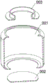
At present, in the processing of stainless steel articles, a laser welding machine is generally used for welding, so that welding seams at welding positions of the stainless steel articles are attractive and uniform, and the stainless steel articles can be conveniently processed in subsequent processes, common stainless steel articles such as a stainless steel kettle and the like can be welded by the laser welding machine, the existing stainless steel kettle is generally divided into three parts including a kettle body 001, a bottom cover 002 and an upper cover 003 as shown in the attached drawing 1 of the specification, openings are formed in the upper part and the lower part of the kettle body 001 for welding the bottom cover 002 and the upper cover 003, the kettle body is usually positioned and clamped firstly in the laser welding process, the kettle body is welded with the bottom cover or the upper cover through a laser welding head, then the welded kettle body is taken down, and then the other part of the kettle body, the bottom cover and the upper cover is clamped and welded by another welding machine, so that the kettle body, the bottom cover and the upper cover need to be clamped twice and taken down once in the welding process, the welding steps are multiple and cumbersome, the production efficiency of the kettle is influenced, and the investment of equipment is larger.
Disclosure of Invention
The purpose of the invention is: aims to provide a laser welding machine which is used for solving the problems existing in the background technology.
In order to achieve the technical purpose, the technical scheme adopted by the invention is as follows:
a laser welding machine comprises a workbench, an electric cabinet, an inner support framework, two welding clamping mechanisms and a laser welding mechanism, wherein the workbench is provided with a circular through groove, the circular through groove is connected with a circular rotary table electrically connected with the electric cabinet in a rotating manner, the number of the inner support frameworks is two, each inner support framework is integrally formed by a C-shaped part and a vertical part, the C-shaped part is matched with the inner wall of a kettle body, the lower end of the C-shaped part horizontally extends to the inner side of an opening at the bottom of the kettle body, the vertical part is positioned at the upper side end part of the C-shaped part, the vertical part is matched with an opening of an upper cover and extends outwards, the two C-shaped parts are symmetrically arranged and are fixed through a spring telescopic rod, the welding clamping mechanism is arranged on the inner side of the circular rotary table, and comprises two positioning plates, two clamping plates and a group of clamping components, the two positioning plates are respectively arranged on two symmetrical sides of the circular rotary table, the circular rotary table is provided with a band-type brake motor, an output shaft of the band-type brake motor is fixedly connected with the middle part of one of the positioning plates, a first rotating shaft is rotatably connected between the circular rotary table and the middle part of the other positioning plate, the clamping assembly comprises two connecting rods, a horizontal sliding rail and two clamping claws, the two connecting rods are respectively and fixedly connected with the two positioning plates, the upper ends of the two connecting rods are fixedly connected with the horizontal sliding rail together, the end parts of the two clamping claws are both in sliding connection with the horizontal sliding rail, the horizontal sliding rail is provided with an adjusting locking assembly matched with the two clamping claws, the two clamping plates are positioned on one side opposite to the two positioning plates, and both ends of the two positioning plates are in damping sliding connection with a sliding rod, the clamping plate is fixedly connected with the sliding rod, one side of the clamping plate facing to the sliding rod is provided with a placing groove matched with the kettle body, the laser welding mechanism comprises a rack extending towards the center of the circular rotary table, a laser welding head and a first driving mechanism are installed at the end part of the rack, and the first driving mechanism is used for driving and adjusting the position of the laser welding head.
The adjusting locking assembly comprises a second rotating shaft, two ends of the second rotating shaft are rotated to penetrate through the horizontal sliding rail, positive-rotation threads and negative-rotation threads are processed on two sides of the second rotating shaft respectively, and the end portions of the clamping claws are connected with threads on two sides of the second rotating shaft respectively.
Compass handles are fixedly arranged at two ends of the second rotating shaft, and a supporting table matched with the second rotating shaft is arranged in the middle of the horizontal sliding rail.
The first driving mechanism comprises a first longitudinal electric cylinder and a horizontal electric cylinder, the first longitudinal electric cylinder is connected with the rack in a sliding mode, the laser welding head is fixedly connected with the telescopic end of the first longitudinal electric cylinder, the horizontal electric cylinder is horizontally fixed with the rack along the extending direction of the rack, and the telescopic end of the horizontal electric cylinder is fixedly connected with the first longitudinal electric cylinder.
The clamping jaw is arc-shaped and matched with the kettle body, and a plurality of rubber strips are bonded on the surface of the clamping jaw.
The pressing mechanism is further installed at the end portion of the rack and comprises a bearing turntable, a second longitudinal electric cylinder and a C-shaped pressing block, the bearing turntable is connected with the rack in a rotating mode and located right above the center of the circular ring turntable, the second longitudinal electric cylinder is vertically fixed on the upper side of the bearing turntable, and two ends of the C-shaped pressing block face downwards, the upper end of the C-shaped pressing block is fixedly connected with the telescopic end of the second longitudinal electric cylinder.
The bearing turntable is provided with a rotary locking assembly between the frame, the rotary locking assembly comprises a first boss and a locking threaded pin, the first boss is fixedly connected with the side face of the frame, the locking threaded pin rotates to penetrate through the first boss and the side face of the bearing turntable in an abutting mode, and the locking threaded pin is in threaded connection with the first boss.
The bearing turntable and the rack are both provided with indication scales.
The utility model discloses a clamping plate, including the fixed locating plate of clamping plate, the fixed locating plate of clamping plate one end is equipped with the fixed guide bar that is provided with of second boss, the fixed locating plate of clamping plate one end is equipped with the fixed locating plate of clamping plate one end, and the fixed locating plate of clamping plate is equipped with the guide bar, the guide bar inserts to the semicircular groove, semicircular groove is close to second boss one end with semicircular groove keeps away from second boss one end staggers each other and its interval of staggering equals the maximum translation distance of clamping plate.
The welding device can weld the kettle body, the upper cover and the lower cover of the stainless steel kettle on one device, does not need secondary clamping and detaching in the machining process, and only needs to correspondingly adjust the welding position of the laser welding head, thereby reducing the investment of the device and improving the production efficiency of the stainless steel kettle.
Drawings
The invention is further illustrated by the non-limiting examples given in the figures.
FIG. 1 is a schematic view of a prior art kettle;
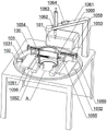
FIG. 2 is a schematic diagram of a state structure of step (3) according to the first embodiment of the present invention;
FIG. 3 is an enlarged view of the structure at A in FIG. 2;
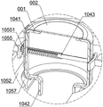
FIG. 4 is a state diagram of step (6) according to the first embodiment of the present invention;
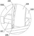
FIG. 5 is an enlarged view of the structure at B in FIG. 4;
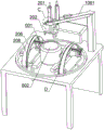
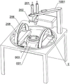
FIG. 6 is a schematic diagram of the state structure of step (3) in the second embodiment of the present invention;
FIG. 7 is an enlarged view of the structure at C of FIG. 6;
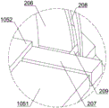
FIG. 8 is an enlarged view of the structure at D in FIG. 6;
FIG. 9 is a schematic diagram of the state of step (6) in the second embodiment of the present invention;
FIG. 10 is an enlarged view of the structure at E in FIG. 9;
the main component symbols are as follows:
the kettle of the prior art: a kettle body 001, a bottom cover 002 and an upper cover 003;
the first embodiment is as follows: the device comprises a workbench 100, an electric cabinet 101, a circular through groove 102, a circular ring rotary table 103, a band-type brake motor 1031, a first rotating shaft 1032, a C-shaped part 1041, a vertical part 1042, a spring telescopic rod 1043, a positioning plate 1051, a clamping plate 1052, a connecting rod 1053, a horizontal sliding rail 1054, a clamping jaw 1055, rubber strips 10551, a sliding rod 1056, a placing groove 1057, a second rotating shaft 1058, a compass handle 1059, a supporting table 1060, a rack 1061, a laser welding head 1062, a first longitudinal electric cylinder 1063 and a horizontal electric cylinder 1064;
example two: the bearing rotary table comprises a bearing rotary table 200, a second longitudinal electric cylinder 201, a C-shaped pressing block 202, a first boss 203, a locking threaded pin 204, an indication scale 205, a semicircular ring plate 206, a second boss 207, a semicircular ring groove 208 and a guide rod 209.
Detailed Description
In order that those skilled in the art can better understand the present invention, the following technical solutions are further described with reference to the accompanying drawings and examples.
The first embodiment is as follows:
as shown in fig. 1 to 5, the laser welding machine includes a workbench 100, an electric cabinet 101, two inner support frames, a welding and clamping mechanism and a laser welding mechanism, the workbench 100 is provided with a circular through groove 102, the circular through groove 102 is rotatably connected with a circular turntable 103 electrically connected with the electric cabinet 101, the number of the inner support frames is two, each inner support frame is integrally formed by a C-shaped portion 1041 and a vertical portion 1042, the C-shaped portion 1041 is matched with the inner wall of a kettle body 001, the lower end of the C-shaped portion 1041 horizontally extends to the inner side of an opening at the bottom of the kettle body 001, the vertical portion 1042 is located at the upper end of the C-shaped portion 1041, the vertical portion 1042 is matched with an opening of an upper cover 003 and extends outwards, and the two C-shaped portions 1041 are symmetrically arranged and fixed by a spring telescopic rod 1043;
the welding clamping mechanism is arranged on the inner side of the circular rotary table 103 and comprises two positioning plates 1051, two clamping plates 1052 and a group of clamping components, the two positioning plates 1051 are respectively arranged on two symmetrical sides of the circular rotary table 103, the circular rotary table 103 is provided with a band-type brake motor 1031, an output shaft of the band-type brake motor 1031 is fixedly connected with the middle part of one positioning plate 1051, a first rotating shaft 1032 is rotatably connected between the circular rotary table 103 and the middle part of the other positioning plate 1051, the clamping components comprise two connecting rods 1053, a horizontal sliding rail 1054 and two clamping claws 1055, the two connecting rods 1053 are respectively fixedly connected with the two positioning plates 1051, the upper ends of the two connecting rods 1053 are commonly and fixedly connected with the horizontal sliding rail 1054, the end parts of the two clamping claws 1055 are respectively and slidably connected with the horizontal sliding rail 1054, the horizontal sliding rail 1054 is provided with adjusting and locking components matched with the two clamping claws 1055, the adjusting locking components comprise a second rotating shaft 1058, two ends of the second rotating shaft 1058 rotatably penetrate through the horizontal sliding rail 1054, and two sides of the second rotating shaft 1058 are respectively processed with a positive thread and a reverse thread 1058;
the two clamping plates 1052 are positioned at one opposite sides of the two positioning plates 1051, the two ends of the two positioning plates 1051 are in damping sliding connection with a sliding rod 1056, the clamping plates 1052 are fixedly connected with the sliding rod 1056, and one opposite sides of the two clamping plates 1052 are provided with placing grooves 1057 matched with the kettle body 001;
the laser welding mechanism comprises a machine frame 1061 extending towards the center of the circular turntable 103, a laser welding head 1062 and a first driving mechanism are mounted at the end of the machine frame 1061, the first driving mechanism is used for driving and adjusting the position of the laser welding head 1062, the first driving mechanism comprises a first longitudinal electric cylinder 1063 and a horizontal electric cylinder 1064, the first longitudinal electric cylinder 1063 is connected with the machine frame 1061 in a sliding manner, the laser welding head 1062 is fixedly connected with the telescopic end of the first longitudinal electric cylinder 1063, the horizontal electric cylinder 1064 is horizontally fixed with the machine frame 1061 along the extending direction of the machine frame 1061, and the telescopic end of the horizontal electric cylinder 1064 is fixedly connected with the first longitudinal electric cylinder 1063.
The inner support frameworks can support the kettle body 001 through the C-shaped part 1041, the lower side of the C-shaped part 1041 extends to the inner side of an opening in the bottom of the kettle body 001, when the kettle body 001 is inverted, as shown in fig. 3, the C-shaped part 1041 can place and support the bottom cover 002, welding of the bottom cover 002 is facilitated, meanwhile, the vertical part 1042 of the C-shaped part 1041 is matched with an opening of the upper cover 003, when the kettle body 001 is placed right, as shown in fig. 5, the upper cover 003 can be placed and supported through the upper side of the C-shaped part 1041, the vertical part 1042 can penetrate through the opening of the upper cover 003 to be positioned, and the two C-shaped parts 1041 are mutually symmetrical and are connected with the spring telescopic rods 1043, so that after welding of the kettle body 001, the bottom cover 002 and the upper cover 003 is completed, people only need to forcibly pinch the two vertical parts 1042, the width between the two inner support frameworks can be reduced, and the two inner support frameworks are taken out of the opening of the upper cover 003;
before the device is used, the band-type brake motor 1031 rotates to enable the positioning plates 1051 connected with the output shaft of the band-type brake motor 1031 to rotate to be horizontal, and because the two positioning plates 1051 are connected into a whole through the two connecting rods 1053 and the horizontal sliding rails 1054, the two positioning plates 1051 both rotate to be horizontal, and because the two clamping plates 1052 are connected with the two positioning plates 1051 through the sliding slide rods 1056 with damping, the two clamping plates 1052 can also rotate to be horizontal, so that people rotate the welding clamping mechanism through the band-type brake motor 1031 to enable the welding clamping mechanism to rotate to be horizontal, the placing grooves 1057 of the two clamping plates 1052 are upward, and the output shaft of the band-type brake motor 1031 can not rotate after being stopped, so that the welding clamping mechanism is stabilized in the horizontal state, as shown in the state of fig. 2;
in the using process of the device, the method comprises the following steps:
step (1): the inner support frameworks are arranged in the kettle body 001, the two vertical parts 1042 are pinched forcibly, the spring telescopic rods 1043 are pinched to reduce the width of the two inner support frameworks, the two inner support frameworks enter the interior of the kettle body 001, then the spring telescopic rods 1043 rebound to enable the C-shaped parts 1041 of the two inner support frameworks to support the two sides of the kettle body 001 internally, at the moment, as shown in fig. 3, the vertical parts 1041 of the C-shaped parts 1041 support the side walls of the kettle body 001, the lower ends of the C-shaped parts 1041 support the lower side of the kettle body 001, the upper ends of the C-shaped parts 1041 support the upper side of the kettle body 001, and the vertical parts 1042 upwards penetrate through the kettle body 001;
step (2): the two clamping plates 1052 are pulled to enable the two clamping plates 1052 to slide relative to the positioning plate 1051 to be far away to the maximum distance, the two clamping plates 1052 are close, people place the kettle body 001 upside down and support the kettle body through the placing grooves 1057 of the two clamping plates 1052, the two clamping plates 1052 are in sliding connection with the two positioning plates 1051 through the sliding rods 1056 with damping sliding, so that the two clamping plates 1052 cannot be loosened, when the kettle body 001 is placed upside down, the two inner supporting frameworks correspond to the two clamping claws 1055, and at the moment, the bottom opening of the kettle body 001 faces upwards, as shown in figure 2,
and (3): the bottom cover 002 is placed at the upward bottom opening of the kettle body 001 and is supported by the C-shaped parts 1041 of the two inner support frameworks, at the moment, people can adjust the two clamping claws 1055 by using the adjusting and locking assembly, when the kettle is used, the second rotating shaft 1058 of the horizontal sliding rail 1054 is rotated, and the end parts of the two clamping claws 1055 are respectively matched with the threads of the forward-rotating threads and the backward-rotating threads at the two sides of the second rotating shaft 1058, so that the two clamping claws 1055 are close to each other in the horizontal sliding rail 1054 to clamp the outer wall of the kettle body 001, as shown in fig. 2, the two inner support frameworks correspond to the two clamping claws 1055 in position, so that the buffering effect of the clamping part of the kettle body 001 can be achieved, and the kettle body 001 is prevented from being deformed;
and (4): the first driving mechanism is started, the laser welding head 1062 is lowered to the required welding height through the first longitudinal electric cylinder 1063, and the horizontal electric cylinder 1064 pushes the first longitudinal electric cylinder 1063 to move along the extending direction of the rack 1061, so as to control the alignment of the laser welding head 1062 with the welding seam of the bottom cover 001 and the kettle body 001;
and (5): the laser welding head 1062 and the electric cabinet 101 are synchronously started, so that the circular ring rotary table 103 rotates for a circle, the welding seam of the bottom cover 001 and the kettle body 001 rotates for a circle around the laser welding head 1062, and the bottom cover 001 and the kettle body 001 are welded and fixed through the laser welding head 1062;
and (6): after the welding of the bottom cover 002 is completed, after the laser welding mechanism is controlled to return, the band-type brake motor 1031 is started again to rotate for a half cycle, so that the welding clamping mechanism rotates for a half cycle, at the moment, as shown in fig. 4, people push the two clamping plates 1052 to be close to the two positioning plates 1051 respectively, at the moment, the kettle body 001 returns to the positive state, at the same time, the two clamping plates 1052 do not shield the opening on the upper side of the kettle body 001, people place the upper cover 003 on the upper side of the positive kettle body 001, as shown in fig. 5, the upper cover 003 is supported through the C-shaped part 1041, meanwhile, the vertical part 1042 is used for positioning the upper cover 003, the laser welding mechanism is controlled again, according to the action in the step (4), a laser welding head 1062 is aligned with the welding line of the upper cover 003 and the kettle body 001, and finally, according to the action in the step (5), the upper cover 003 and the kettle body 001 are welded and fixed, and the kettle is welded;
and (7): two clamping claws 1055 are loosened by adjusting the locking assembly, the kettle is loosened, then the two vertical parts 1042 are pinched with force, the width between the two inner supporting frameworks can be reduced, and the two inner supporting frameworks can be taken out from the opening of the upper cover 003.
As a further optimization of the present embodiment, as shown in fig. 2 to fig. 5, compass handles 1059 are fixedly disposed at both ends of the second rotating shaft 1058, a supporting platform 1060 matched with the second rotating shaft 1058 is disposed in the middle of the horizontal sliding rail 1054, the clamping jaw 1055 is arc-shaped and matched with the kettle body 001, and a plurality of rubber strips 10551 are bonded on the surface of the clamping jaw 1055.
Through setting up compass handle 1059 at second pivot 1058 both ends, can make things convenient for people to rotate second pivot 1058 from the arbitrary one end of second pivot 1058, supporting bench 1060 that sets up at horizontal slide rail 1054 simultaneously can make second pivot 1058 obtain supporting, and the stability is improved, and set up gripper jaw 1055 into circular-arcly, can increase the contact surface with kettle body 001, the centre gripping is more stable, the rubber strip 10551 on gripper jaw 1055 surface can play the buffering centre gripping and avoid rigidity mar effect.
Example two:
on the basis of the first embodiment, in order to avoid the problem of welding quality caused by the rotation deviation of the bottom cover 002 and the upper cover 003 in the welding process of the bottom cover 002 and the upper cover 003, as shown in fig. 6, 7 and 9, a pressing mechanism is further installed at the end of the rack 1061, the pressing mechanism comprises a bearing turntable 200, a second longitudinal electric cylinder 201 and a C-shaped pressing block 202, the bearing turntable 200 is rotatably connected with the rack 1061 and is positioned right above the center of the circular turntable 103, the second longitudinal electric cylinder 201 is vertically fixed on the upper side of the bearing turntable 200, and two ends of the C-shaped pressing block 202 face downward and the upper end of the C-shaped pressing block is fixedly connected with the telescopic end of the second longitudinal electric cylinder 201;
a rotation locking assembly is arranged between the bearing turntable 200 and the rack 1061, the rotation locking assembly comprises a first boss 203 and a locking threaded pin 204, the first boss 203 is fixedly connected with the side surface of the rack 1061, the locking threaded pin 204 rotates to penetrate through the first boss 203 to be abutted against the side surface of the bearing turntable 200, and the locking threaded pin 204 is in threaded connection with the first boss 203.
In the process of step (4), as shown in fig. 6, the rotation locking assembly is firstly loosened, the locking threaded pin 204 of the first boss 203 is withdrawn and does not abut against the side surface of the bearing turntable 200, at this time, one can rotate the bearing turntable 200 to adjust the orientation of the C-shaped pressing block 202, so that the two ends of the C-shaped pressing block 202 correspond to the two clamping claws 1055, and then rotate to make the locking threaded pin 204 abut against the side surface of the bearing turntable 200, the bearing turntable 200 does not rotate any more, and the C-shaped pressing block 202 moves downwards through the second longitudinal electric cylinder 201 to make the C-shaped pressing block 202 press the bottom cover 002 tightly, because the two clamping claws 1055 correspond to the two inner support framework positions, the bottom cover 002 is pressed and fixed with the C-shaped pressing block 202 through the C-shaped portion 1041, so that the bottom cover 002 is not deformed while pressing, after pressing, the rotation locking assembly is loosened, under the friction force of the C-shaped portion 1041 and the bottom cover 002 and the friction force of the C-shaped pressing block 202, the rotation of the bearing turntable 200 is driven to rotate, so that the C-shaped pressing block 202 does not interfere with the subsequent step (5), and the pressing operation of step (6) is the step (9).
Further optimization, as shown in fig. 7, the bearing turntable 200 and the rack 1061 are both further processed with indication scales 205, and by means of the indication scales 205, when the bearing turntable 200 is aligned with the indication scales 205 of the rack 1061, the C-shaped press block 202 can correspond to the positions of the two clamping claws 1055, so that the position can be adjusted quickly by people.
Simultaneously, for further messenger clamping plate 1052 can automatic roll back, need artifical promotion clamping plate 1052 in step (6) is avoided, make further improvement, as shown in fig. 6-10, ring revolving stage 103 inboard still is provided with automatic telescopic machanism, automatic telescopic machanism is including two semicircle ring boards 206, two semicircle ring boards 206 all fix mutually with ring revolving stage 103 and respectively with two locating plates 1051 corresponding, two equal fixedly connected with second boss 207 of clamping plate 1052 one end, semicircle hoop groove 208 has all been seted up on each semicircle ring board 206 surface, second boss 207 is fixed to be provided with guide bar 209, guide bar 209 inserts semicircle hoop groove 208, semicircle hoop groove 208 is close to second boss 207 one end and keeps away from second boss 207 one end and staggers each other and its the biggest translation distance that staggers the interval and equals clamping plate 1052 with semicircle hoop groove 208.
In the process of step (6), the guide rods 209 of the second bosses 207 of the two clamping plates 1052 move along the semicircular annular grooves 208 on the surface of the semicircular annular plate 206, and since one ends of the semicircular annular grooves 208, which are close to the second bosses 207, and one ends of the semicircular annular grooves 208, which are far away from the second bosses 207, are staggered with each other and the staggered distance is equal to the maximum translation distance of the clamping plates 1052, after the rotation of the two clamping plates 1052 for half a circle, the two clamping plates 1052 can automatically retract to be close to the two positioning plates 1051 under the guidance of the guide rods 209, as shown in the comparison between fig. 8 and fig. 10, so that manual operation is avoided, and the positions of the two clamping plates 1052 are further stabilized through the positioning of the guide rods 209 and the semicircular annular grooves 208.
The foregoing embodiments are merely illustrative of the principles of the present invention and its efficacy, and are not to be construed as limiting the invention. Any person skilled in the art can modify or change the above-mentioned embodiments without departing from the spirit and scope of the present invention. Accordingly, it is intended that all equivalent modifications or changes which can be made by those skilled in the art without departing from the spirit and technical spirit of the present invention be covered by the claims of the present invention.
Claims (9)
1. The utility model provides a laser welding machine, includes workstation, electric cabinet, interior support skeleton, welding clamping mechanism and laser welding machine structure, circular logical groove has been seted up to the workstation, circular logical inslot rotation be connected with electric cabinet electric connection's ring revolving stage, its characterized in that: the number of the inner support frameworks is two, each inner support framework is integrally formed by a C-shaped part and a vertical part, the C-shaped part is matched with the inner wall of the kettle body, the lower end of the C-shaped part horizontally extends to the inner side of an opening at the bottom of the kettle body, the vertical part is positioned at the upper end part of the C-shaped part, the vertical part is matched with an opening of the upper cover and extends outwards, and the two C-shaped parts are symmetrically arranged and fixed through spring telescopic rods;
the welding clamping mechanism is arranged on the inner side of the circular rotary table and comprises two positioning plates, two clamping plates and a group of clamping components, the two positioning plates are respectively arranged on two symmetrical sides of the circular rotary table, the circular rotary table is provided with a band-type brake motor, an output shaft of the band-type brake motor is fixedly connected with the middle part of one of the positioning plates, a first rotating shaft is rotatably connected between the circular rotary table and the middle part of the other positioning plate, the clamping components comprise two connecting rods, a horizontal sliding rail and two clamping claws, the two connecting rods are respectively and fixedly connected with the two positioning plates, the upper ends of the two connecting rods are commonly and fixedly connected with the horizontal sliding rail, the end parts of the two clamping claws are both in sliding connection with the horizontal sliding rail, and the horizontal sliding rail is provided with an adjusting and locking component matched with the two clamping claws;
the two clamping plates are positioned on one sides of the two opposite positioning plates, two ends of the two positioning plates are connected with a sliding rod in a damping sliding mode, the clamping plates are fixedly connected with the sliding rod, and one sides of the two opposite clamping plates are provided with placing grooves matched with the kettle body;
the laser welding mechanism comprises a machine frame extending towards the center of the circular rotary table, a laser welding head and a first driving mechanism are mounted at the end of the machine frame, and the first driving mechanism is used for driving and adjusting the position of the laser welding head.
2. A laser welding machine as defined in claim 1, wherein: the adjusting locking assembly comprises a second rotating shaft, two ends of the second rotating shaft are rotated to penetrate through the horizontal sliding rail, positive-rotation threads and negative-rotation threads are machined on two sides of the second rotating shaft respectively, and the end portions of the clamping jaws are connected with threads on two sides of the second rotating shaft respectively.
3. A laser welding machine according to claim 2, characterized in that: compass handles are fixedly arranged at two ends of the second rotating shaft, and a supporting table matched with the second rotating shaft is arranged in the middle of the horizontal sliding rail.
4. A laser welder according to claim 3, characterized in that: the first driving mechanism comprises a first longitudinal electric cylinder and a horizontal electric cylinder, the first longitudinal electric cylinder is connected with the rack in a sliding mode, the laser welding head is fixedly connected with the telescopic end of the first longitudinal electric cylinder, the horizontal electric cylinder is horizontally fixed with the rack along the extending direction of the rack, and the telescopic end of the horizontal electric cylinder is fixedly connected with the first longitudinal electric cylinder.
5. The laser welding machine according to claim 4, characterized in that: the gripper jaw is circular-arc with kettle body assorted, just gripper jaw surface bonds has a plurality of rubber strips.
6. The laser welding machine according to claim 5, characterized in that: the pressing mechanism is further installed at the end portion of the rack and comprises a bearing turntable, a second longitudinal electric cylinder and a C-shaped pressing block, the bearing turntable is connected with the rack in a rotating mode and located right above the center of the circular ring turntable, the second longitudinal electric cylinder is vertically fixed on the upper side of the bearing turntable, and two ends of the C-shaped pressing block face downwards, the upper end of the C-shaped pressing block is fixedly connected with the telescopic end of the second longitudinal electric cylinder.
7. A laser welding machine according to claim 6, characterized in that: the bearing turntable is provided with a rotary locking assembly between the frame, the rotary locking assembly comprises a first boss and a locking threaded pin, the first boss is fixedly connected with the side face of the frame, the locking threaded pin rotates to penetrate through the first boss and the side face of the bearing turntable in an abutting mode, and the locking threaded pin is in threaded connection with the first boss.
8. A laser welding machine as defined in claim 7, wherein: the bearing turntable and the rack are both provided with indication scales.
9. A laser welder according to claim 8, characterized in that: the utility model discloses a fixed clamping plate, including the fixed clamping plate of circle revolving stage, the fixed clamping plate of circle revolving stage is equipped with the locating plate, the locating plate is equipped with the semicircular ring groove, the semicircular ring groove is equipped with the guide bar, the guide bar inserts to semicircular ring groove, semicircular ring groove is close to second boss one end with semicircular ring groove is kept away from second boss one end staggers each other and its interval of staggering equals the biggest translation distance of clamping plate.
Priority Applications (1)
| Application Number | Priority Date | Filing Date | Title |
|---|---|---|---|
| CN202211576438.5A CN115570269B (en) | 2022-12-09 | 2022-12-09 | Laser welding machine |
Applications Claiming Priority (1)
| Application Number | Priority Date | Filing Date | Title |
|---|---|---|---|
| CN202211576438.5A CN115570269B (en) | 2022-12-09 | 2022-12-09 | Laser welding machine |
Publications (2)
| Publication Number | Publication Date |
|---|---|
| CN115570269A CN115570269A (en) | 2023-01-06 |
| CN115570269B true CN115570269B (en) | 2023-04-07 |
Family
ID=84590147
Family Applications (1)
| Application Number | Title | Priority Date | Filing Date |
|---|---|---|---|
| CN202211576438.5A Active CN115570269B (en) | 2022-12-09 | 2022-12-09 | Laser welding machine |
Country Status (1)
| Country | Link |
|---|---|
| CN (1) | CN115570269B (en) |
Families Citing this family (1)
| Publication number | Priority date | Publication date | Assignee | Title |
|---|---|---|---|---|
| CN115805513B (en) * | 2023-02-06 | 2023-04-11 | 汕头市杰森智能科技有限公司 | A polishing equipment for kettle |
Citations (9)
| Publication number | Priority date | Publication date | Assignee | Title |
|---|---|---|---|---|
| CN205614260U (en) * | 2016-05-11 | 2016-10-05 | 台州市菲克激光设备有限公司 | Location hold -down mechanism and welding machine |
| CN206854847U (en) * | 2017-07-03 | 2018-01-09 | 福建省石狮市中兴科技有限公司 | A kind of military stainless steel heat-insulation water bottle automatic laser welding equipment |
| CN109822219A (en) * | 2019-02-27 | 2019-05-31 | 惠州市通发激光设备有限公司 | A kind of kettle welder with seamless welding function |
| CN209256051U (en) * | 2018-12-03 | 2019-08-16 | 西安市双安基业人防工程有限公司 | A kind of two guarantor's welding machine of flange automatic positioning |
| CN111889879A (en) * | 2020-07-25 | 2020-11-06 | 远特信电子(深圳)有限公司 | Laser welding machine |
| CN212350946U (en) * | 2020-08-21 | 2021-01-15 | 中山汉通激光设备有限公司 | Laser kettle welding frock clamp |
| CN212946035U (en) * | 2020-07-25 | 2021-04-13 | 远特信电子(深圳)有限公司 | Laser welding machine |
| CN214054141U (en) * | 2020-11-30 | 2021-08-27 | 新疆特变电工集团有限公司 | Electric automatization welding equipment |
| CN217253870U (en) * | 2022-03-03 | 2022-08-23 | 株洲特装智能装备有限公司 | Automatic welding device of kettle |
-
2022
- 2022-12-09 CN CN202211576438.5A patent/CN115570269B/en active Active
Patent Citations (9)
| Publication number | Priority date | Publication date | Assignee | Title |
|---|---|---|---|---|
| CN205614260U (en) * | 2016-05-11 | 2016-10-05 | 台州市菲克激光设备有限公司 | Location hold -down mechanism and welding machine |
| CN206854847U (en) * | 2017-07-03 | 2018-01-09 | 福建省石狮市中兴科技有限公司 | A kind of military stainless steel heat-insulation water bottle automatic laser welding equipment |
| CN209256051U (en) * | 2018-12-03 | 2019-08-16 | 西安市双安基业人防工程有限公司 | A kind of two guarantor's welding machine of flange automatic positioning |
| CN109822219A (en) * | 2019-02-27 | 2019-05-31 | 惠州市通发激光设备有限公司 | A kind of kettle welder with seamless welding function |
| CN111889879A (en) * | 2020-07-25 | 2020-11-06 | 远特信电子(深圳)有限公司 | Laser welding machine |
| CN212946035U (en) * | 2020-07-25 | 2021-04-13 | 远特信电子(深圳)有限公司 | Laser welding machine |
| CN212350946U (en) * | 2020-08-21 | 2021-01-15 | 中山汉通激光设备有限公司 | Laser kettle welding frock clamp |
| CN214054141U (en) * | 2020-11-30 | 2021-08-27 | 新疆特变电工集团有限公司 | Electric automatization welding equipment |
| CN217253870U (en) * | 2022-03-03 | 2022-08-23 | 株洲特装智能装备有限公司 | Automatic welding device of kettle |
Also Published As
| Publication number | Publication date |
|---|---|
| CN115570269A (en) | 2023-01-06 |
Similar Documents
| Publication | Publication Date | Title |
|---|---|---|
| CN115570269B (en) | Laser welding machine | |
| CN218874283U (en) | Cabinet body panel processing welding set | |
| CN211136253U (en) | Automatic processing equipment for surface holes of door and window materials | |
| CN112157378A (en) | Multistation seat weldment work station | |
| CN216464149U (en) | Material positioning and clamping device | |
| CN215035484U (en) | Multi freedom frock clamp | |
| CN216829352U (en) | Aluminium alloy welding machine is used in door and window production | |
| CN215787893U (en) | Automatic production welding equipment for stainless steel hanger | |
| CN115740890A (en) | Welding device and welding process for stainless steel sheet metal parts | |
| CN214109330U (en) | Automatic welding device | |
| CN212945999U (en) | Spot welding machine | |
| CN114769918B (en) | Laser welding equipment for automobile sheet metal parts and application method of laser welding equipment | |
| CN112222746A (en) | Automatic pipe welding equipment | |
| CN220782743U (en) | Fixing device for spot welding of aluminum alloy workpiece | |
| CN219234381U (en) | Positioning frame for welding automobile parts | |
| CN116079303B (en) | Automatic welding device and method for motor coil | |
| CN220825603U (en) | Double-station die changing vehicle welding device | |
| CN218426598U (en) | Universal tool clamp | |
| CN216912695U (en) | Metal piece group welding tool | |
| CN220196254U (en) | Spin riveting machine for processing steel structure fittings of environmental protection equipment | |
| CN219746761U (en) | Profile steel welding device | |
| CN218311595U (en) | XY axle welding machine | |
| CN116705502B (en) | Transformer winding equipment and method | |
| CN219818654U (en) | Welding fixing device for machining mechanical parts | |
| CN219212086U (en) | Clamping device for spot welding processing of metal products |
Legal Events
| Date | Code | Title | Description |
|---|---|---|---|
| PB01 | Publication | ||
| PB01 | Publication | ||
| SE01 | Entry into force of request for substantive examination | ||
| SE01 | Entry into force of request for substantive examination | ||
| GR01 | Patent grant | ||
| GR01 | Patent grant |