CN216829352U - Aluminium alloy welding machine is used in door and window production - Google Patents
Aluminium alloy welding machine is used in door and window production Download PDFInfo
- Publication number
- CN216829352U CN216829352U CN202220294343.3U CN202220294343U CN216829352U CN 216829352 U CN216829352 U CN 216829352U CN 202220294343 U CN202220294343 U CN 202220294343U CN 216829352 U CN216829352 U CN 216829352U
- Authority
- CN
- China
- Prior art keywords
- welding
- motor
- gear
- door
- welding machine
- Prior art date
- Legal status (The legal status is an assumption and is not a legal conclusion. Google has not performed a legal analysis and makes no representation as to the accuracy of the status listed.)
- Active
Links
Images


Abstract
The utility model discloses an aluminum profile welding machine for door and window production, which comprises a workbench, a welding unit and a limiting unit; the left side and the rear side of the upper end of the workbench are provided with limit units; the welding unit includes I-shaped slider, L shape support, telescopic link, connecting rod, soldered connection, gear and movable assembly, the spout has been seted up to the upper end middle part diagonal position of workstation, and the middle part of the inner wall sliding connection I-shaped slider of spout, the lower extreme of the upper end fixed connection L shape support of I-shaped slider, the other end downside of L shape support is equipped with the telescopic link, vertical logical groove has been seted up to the lower extreme of telescopic link, and the one end of axis of rotation swing joint connecting rod is passed through to the inner wall that leads to the groove, and its structural design is higher to welded stability, is difficult for leading to the material to take place the skew in the welding process, has promoted the welded quality, and the welding is comparatively nimble, need not continuous transform material position during the welding, has promoted welding efficiency.
Description
Technical Field
The utility model relates to an aluminium alloy processing technology field specifically is an aluminium alloy welding machine is used in door and window production.
Background
The aluminum profile is a material with wide application, various aluminum profiles are required to be welded to form a structure suitable for actual use scenes according to specific use scenes, the aluminum profiles are frequently used for manufacturing a supporting structure of a door window in the existing building engineering, the conventional technical means is manual welding, the manual welding efficiency is low, and the manual welding can also bring influence on human health.
The patent of publication number CN205290158U discloses among the prior art discloses a be applied to welding machine of aluminium alloy production and processing, including work platform, welding mechanism and fixed establishment, the last welding mechanism and the fixed establishment of being equipped with of work platform, the last cutting board that is equipped with of work platform, be equipped with the clearance through-hole on the cutting board, welding mechanism includes the welding head, rotary device and mobile device, the welding head is fixed on rotary device, rotary device includes carousel and mobile frame, mobile device includes the carriage release lever, telescopic link and fixed support pole, the carriage release lever is connected to the fixed support pole upper end, the telescopic link is connected to the carriage release lever, the telescopic link is followed the carriage release lever horizontal slip, telescopic link fixed connection mobile frame, fixed establishment includes clamping device and lower clamping device.
Its structural design is not enough to welded stability, leads to welding process in the material to take place the skew easily, has reduced welded quality, and welds the flexibility not high, needs continuous alternate material position during the welding, has influenced welding efficiency, for this reason, we provide an aluminium alloy welding machine for door and window production.
SUMMERY OF THE UTILITY MODEL
The to-be-solved technical problem of the utility model is to overcome current defect, provide an aluminium alloy welding machine is used in door and window production, its structural design is higher to welded stability, is difficult for leading to material emergence skew in the welding process, has promoted the welded quality, and welds comparatively in a flexible way, need not continuous transform material position during the welding, has promoted welding efficiency, can effectively solve the problem in the background art.
In order to achieve the above object, the utility model provides a following technical scheme: an aluminum profile welding machine for door and window production comprises a workbench, a welding unit and a limiting unit;
a workbench: the left side and the rear side of the upper end of the upper cover are provided with limit units;
a welding unit: include I-shaped slider, L shape support, telescopic link, connecting rod, soldered connection, gear and movable assembly, the spout has been seted up to the upper end middle part diagonal position of workstation, and the middle part of the inner wall sliding connection I-shaped slider of spout, the lower extreme of the upper end fixed connection L shape support of I-shaped slider, the other end downside of L shape support is equipped with the telescopic link, vertical logical groove has been seted up to the lower extreme of telescopic link, and the inner wall that leads to the groove passes through the one end of axis of rotation swing joint connecting rod, and the one end of the one end fixed connection gear of activity, the lower extreme of connecting rod is equipped with the soldered connection, movable assembly is connected in the meshing of gear one.
The workstation keeps the stability of whole operation, at first arrange the material in the workstation during welding, be vertical distribution, then remove along the direction of spout through the I-shaped slider, control L shape support's position, further adjustment welding position, open movable assembly control gear after the position is confirmed and rotate, further drive is changeed epaxial connecting rod and is moved, keep the soldered connection in the place of perpendicular to welding position, the soldered connection during operation, through telescopic link control soldered connection's lift operation, be convenient for adjust operating position, promote welding efficiency.
Further, the movable assembly comprises a first motor support, a first motor and a second gear, the first motor support is arranged on the upper side, located on the first gear, of the lower peripheral side of the telescopic rod, the first motor support is fixedly connected with one end of the first motor, an output shaft of the first motor is fixedly connected with one end of the second gear, the second gear is meshed with the first gear, and an input end of the first motor is electrically connected with an output end of an external power supply through an external control switch group. When the welding head is controlled to move, the first motor on the motor support is started to drive the second gear to rotate, and the first gear is further meshed to facilitate adjustment of a welding angle.
Further, the welding unit still includes motor two, screw rod and fixed block, the front side that the upper end of I-shaped slider is located L shape support is equipped with motor two, the one end of the output shaft screw rod of motor two, the front side that the upper end of workstation is located the spout is equipped with the fixed block, and the front end of fixed block sets up threaded hole, and threaded hole threaded connection screw rod, the input of motor two is connected with external power source's output electricity through external control switch group. When the I-shaped sliding block needs to be controlled to move, the second motor is started to drive the screw rod to rotate, the screw rod is in threaded connection with the fixing block, the I-shaped sliding block is controlled to move along the direction of the sliding groove through rotation, and the welding position is adjusted flexibly.
Furthermore, the limiting unit comprises a positioning block, limiting bolts and a baffle plate, a pair of positioning blocks is arranged on the left side and the rear side of the upper end of the workbench respectively, threaded holes are formed in the left end and the right end of the positioning block, the threaded holes are in threaded connection with the limiting bolts, and the two limiting bolts penetrate through the two ends of the positioning block and rotate the two sides of the outer end of the connecting baffle plate respectively. When placing the material, rotate the spacing bolt on the locating piece, the position of control baffle conveniently carries out the restriction of different positions according to the material of equidimension not, the welding of being convenient for.
Furthermore, still include the limiting plate, the inboard that the upper end of workstation is located the baffle is equipped with the limiting plate, and the limiting plate is equipped with two. When needs carry out the centre gripping to the material, arrange the aluminium alloy in between baffle and the limiting plate, utilize spacing bolt to laminate the baffle in the material surface and support the limiting plate, promote welded stability.
Further, still include the U-shaped groove, a corner of workstation has seted up the U-shaped groove, and U-shaped groove and spout are located same diagonal. The U-shaped groove is convenient for carrying out spin welding on the welding position of the material, increases the welding area, and can enable the welding head to simultaneously weld the two end faces of the material.
Compared with the prior art, the beneficial effects of the utility model are that: this aluminium alloy welding machine is used in door and window production has following benefit:
1. the aluminum profile welding machine for door and window production is provided with the welding joints which can be optionally installed, so that two end surfaces of a material can be welded, the welding flexibility is improved, and the connection strength of the material can be kept;
2. the aluminum profile welding machine for door and window production has the advantages that the use range of the device is widened through the limiting units capable of limiting and clamping, different functions can be adjusted according to different welding requirements, and the welding stability is improved;
3. this aluminium alloy welding machine is used in door and window production, its structural design is higher to welded stability, is difficult for leading to material in the welding process to take place the skew, has promoted the welded quality, and welds comparatively in a flexible way, need not continuous transform material position during the welding, has promoted welding efficiency.
Drawings
FIG. 1 is a schematic structural view of the present invention;
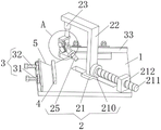
FIG. 2 is a schematic view of a partial enlarged structure at A in FIG. 1 according to the present invention;
fig. 3 is a schematic view of the top view structure of the present invention.
In the figure: the device comprises a working table 1, a welding unit 2, an I-shaped sliding block 21, a 22L-shaped support, a telescopic rod 23, a connecting rod 24, a welding head 25, a first gear 26, a first motor support 27, a first motor 28, a second gear 29, a second motor 210, a screw 211, a 212 fixing block, a limiting unit 3, a positioning block 31, a limiting bolt 32, a baffle 33, a limiting plate 4 and a U-shaped groove 5.
Detailed Description
The technical solutions in the embodiments of the present invention will be described clearly and completely with reference to the accompanying drawings in the embodiments of the present invention, and it is obvious that the described embodiments are only some embodiments of the present invention, not all embodiments. Based on the embodiments in the present invention, all other embodiments obtained by a person skilled in the art without creative work belong to the protection scope of the present invention.
Referring to fig. 1-3, the present embodiment provides a technical solution: an aluminum profile welding machine for door and window production comprises a workbench 1, a welding unit 2 and a limiting unit 3;
a workbench 1: the left side and the rear side of the upper end of the upper part are provided with a limiting unit 3;
the limiting unit 3 comprises a positioning block 31, limiting bolts 32 and a baffle 33, a pair of positioning blocks 31 is respectively arranged on the left side and the rear side of the upper end of the workbench 1, threaded holes are formed in the left end and the right end of each positioning block 31 and connected with the limiting bolts 32 in a threaded mode, and the two limiting bolts 32 penetrate through the two ends of each positioning block 31 and are respectively connected with the two sides of the outer end of the baffle 33 in a rotating mode. When placing the material, the position of the stop bolt 32 on the locating piece 31 is rotated, the position of the baffle 33 is controlled, the limitation of different positions is conveniently carried out according to the materials with different sizes, and the welding is convenient.
The welding unit 2: the automatic welding machine comprises an I-shaped sliding block 21, an L-shaped support 22, a telescopic rod 23, a connecting rod 24, a welding head 25, a first gear 26 and a movable assembly, wherein a sliding groove is formed in the diagonal position of the middle of the upper end of a workbench 1, the inner wall of the sliding groove is connected with the middle of the I-shaped sliding block 21 in a sliding mode, the upper end of the I-shaped sliding block 21 is fixedly connected with the lower end of the L-shaped support 22, the telescopic rod 23 is arranged on the lower side of the other end of the L-shaped support 22, a vertical through groove is formed in the lower end of the telescopic rod 23, the inner wall of the through groove is movably connected with one end of the connecting rod 24 through a rotating shaft, the movable end of the first gear 26 is fixedly connected with one end of the connecting rod 24, the welding head 25 is arranged at the lower end of the connecting rod 24, and the first gear 26 is meshed with the movable assembly.
The workstation 1 keeps the stability of whole operation, at first place the material in workstation 1 during the welding, be vertical distribution, then remove along the direction of spout through I-shaped slider 21, control the position of L shape support 22, further adjustment welding position, open movable assembly control gear 26 after the position is confirmed and rotate, further drive is changeed epaxial connecting rod 24 and is moved, keep soldered connection 25 in the place of perpendicular to welding part, soldered connection 25 during operation, through the lift operation of telescopic link 23 control soldered connection 25, be convenient for adjust operating position, promote welding efficiency.
The movable assembly comprises a first motor support 27, a first motor 28 and a second gear 29, the first motor support 27 is arranged on the upper side, located on the first gear 26, of the lower peripheral side of the telescopic rod 23, the first motor support 27 is fixedly connected with one end of the first motor 28, an output shaft of the first motor 28 is fixedly connected with one end of the second gear 29, the second gear 29 is meshed with the first gear 26, and an input end of the first motor 28 is electrically connected with an output end of an external power supply through an external control switch group. When the welding head 25 is controlled to move, the first motor 28 on the first motor bracket 27 is turned on to drive the second gear 29 to rotate, and further the first gear 26 is engaged, so that the welding angle can be adjusted conveniently.
The welding unit 2 further comprises a second motor 210, a screw 211 and a fixed block 212, the second motor 210 is arranged on the front side, located on the L-shaped support 22, of the upper end of the I-shaped sliding block 21, an output shaft of the second motor 210 is connected with one end of the screw 211, the fixed block 212 is arranged on the front side, located on the sliding groove, of the upper end of the workbench 1, a threaded hole is formed in the front end of the fixed block 212, the threaded hole is connected with the screw 211 in a threaded mode, and the input end of the second motor 210 is electrically connected with the output end of an external power supply through an external control switch set. When the I-shaped sliding block 21 needs to be controlled to move, the second motor 210 is started to drive the screw 211 to rotate, the screw 211 is in threaded connection with the fixing block 212, the I-shaped sliding block 21 is controlled to move along the direction of the sliding groove through rotation, and the welding position is flexibly adjusted.
Still include limiting plate 4, the inboard that the upper end of workstation 1 is located baffle 33 is equipped with limiting plate 4, and limiting plate 4 is equipped with two. When needs carry out the centre gripping to the material, place the aluminium alloy between baffle 33 and limiting plate 4, utilize limit bolt 32 to laminate baffle 33 in the material surface and support limiting plate 4, promote welded stability.
Still include U-shaped groove 5, U-shaped groove 5 has been seted up to a corner of workstation 1, and U-shaped groove 5 and spout are located same diagonal. The U-shaped groove 5 facilitates the rotary welding of the welding position of the materials, increases the welding area, and enables the welding head 25 to simultaneously weld the two end faces of the materials.
The utility model provides a pair of aluminium alloy welding machine is used in door and window production's theory of operation as follows: when the aluminum profile to be processed is placed on the workbench 1, when the material is placed, the limiting bolt 32 on the positioning block 31 is rotated, the position of the baffle 33 is controlled, the limitation of different positions can be conveniently carried out according to the materials with different sizes, the welding is convenient, when the material needs to be clamped, the aluminum profile is placed between the baffle 33 and the limiting plate 4, the baffle 33 is attached to the surface of the material and is propped against the limiting plate 4 by using the limiting bolt 32, the welding stability is improved, after the position is determined, the positions to be welded of two travels are exposed in the U-shaped groove 5, the U-shaped groove 5 is convenient for carrying out rotary welding on the welding position of the material, the welding area is increased, the welding head 25 can simultaneously weld two end faces of the material, when the movement of the I-shaped slider 21 needs to be controlled, the motor II 210 is opened to drive the screw 211 to rotate, the screw 211 is in threaded connection with the fixing block 212, the I-shaped slider 21 is controlled to move along the direction of the chute through rotation, controlling the position of the L-shaped bracket 22, further adjusting the welding position, after the position is determined, turning on a first motor 28 on a first motor bracket 27, driving a second gear 29 to rotate, further engaging a first gear 26, driving a connecting rod 24 on the rotating shaft to move, keeping the welding head 25 at a position vertical to the welding position, when the welding head 25 works, the telescopic rod 23 is used for controlling the lifting operation of the welding head 25, so that the working position can be conveniently adjusted, the welding efficiency is improved, after the welding of the upper end surface of the material is finished, the position of the I-shaped slide block 21 can be moved to the innermost side of the sliding chute, the welding head 25 is lowered by using the telescopic rod 23, and then, the position of the welding head 25 is perpendicular to the telescopic rod 23 by using the first motor 28, the side surfaces of the two aluminum profiles are further welded, the welding flexibility is improved, the materials are taken down after the welding is finished, and the whole welding machine is used completely.
It should be noted that the core chip of the control switch set disclosed in the above embodiments is a PLC single chip, the specific model is mitsubishi FX2N-16MT, the first motor 28 and the second motor 210 can be freely configured according to the actual application scenario, and the first motor 28 and the second motor 210 can be stepping motors. The control switch sets control the operation of the first motor 28 and the second motor 210 using methods commonly used in the art.
The above only is the embodiment of the present invention, not limiting the scope of the present invention, all the equivalent structures or equivalent processes of the present invention are used in the specification and the attached drawings, or directly or indirectly applied to other related technical fields, and the same principle is included in the protection scope of the present invention.
Claims (6)
1. The utility model provides an aluminium alloy welding machine is used in door and window production which characterized in that: comprises a workbench (1), a welding unit (2) and a limiting unit (3);
table (1): the left side and the rear side of the upper end of the lower support are provided with limiting units (3);
welding unit (2): include I-shaped slider (21), L shape support (22), telescopic link (23), connecting rod (24), soldered connection (25), gear (26) and movable assembly, the spout has been seted up to the upper end middle part diagonal position of workstation (1), and the middle part of the inner wall sliding connection I-shaped slider (21) of spout, the lower extreme of the upper end fixed connection L shape support (22) of I-shaped slider (21), the other end downside of L shape support (22) is equipped with telescopic link (23), vertical logical groove has been seted up to the lower extreme of telescopic link (23), and the inner wall that leads to the groove passes through the one end of axis of rotation swing joint connecting rod (24), and the one end of the one end fixed connection gear (26) of activity, the lower extreme of connecting rod (24) is equipped with soldered connection (25), movable assembly is connected in gear (26) meshing.
2. The aluminum profile welding machine for door and window production according to claim 1, characterized in that: the movable assembly includes motor one support (27), motor one (28) and gear two (29), the upside that the peripheral downside of telescopic link (23) is located gear one (26) is equipped with motor one support (27), the one end of motor one support (27) fixed connection motor one (28), the one end of output shaft fixed connection gear two (29) of motor one (28), gear two (29) meshing connection gear one (26), the input of motor one (28) is connected with external power source's output electricity through external control switch group.
3. The aluminum profile welding machine for door and window production according to claim 1, characterized in that: welding unit (2) still include motor two (210), screw rod (211) and fixed block (212), the front side that the upper end of I-shaped slider (21) is located L shape support (22) is equipped with motor two (210), the one end of output shaft screw rod (211) of motor two (210), the front side that the upper end of workstation (1) is located the spout is equipped with fixed block (212), and the front end of fixed block (212) seted up threaded hole, threaded hole threaded connection screw rod (211), the input of motor two (210) is connected with external power source's output electricity through external control switch group.
4. The aluminum profile welding machine for door and window production according to claim 1, characterized in that: spacing unit (3) include locating piece (31), spacing bolt (32) and baffle (33), the upper end left side and the rear side of workstation (1) are equipped with a pair of locating piece (31) respectively, and both ends set up threaded hole about locating piece (31), and threaded hole threaded connection spacing bolt (32), two both ends that spacing bolt (32) passed locating piece (31) rotate the outer end both sides of connecting baffle (33) respectively.
5. The aluminum profile welding machine for door and window production according to claim 4, characterized in that: still include limiting plate (4), the inboard that the upper end of workstation (1) is located baffle (33) is equipped with limiting plate (4), and limiting plate (4) are equipped with two.
6. The aluminum profile welding machine for door and window production according to claim 1, characterized in that: still include U-shaped groove (5), U-shaped groove (5) have been seted up to a corner of workstation (1), and U-shaped groove (5) and spout are located same diagonal.
Priority Applications (1)
| Application Number | Priority Date | Filing Date | Title |
|---|---|---|---|
| CN202220294343.3U CN216829352U (en) | 2022-02-14 | 2022-02-14 | Aluminium alloy welding machine is used in door and window production |
Applications Claiming Priority (1)
| Application Number | Priority Date | Filing Date | Title |
|---|---|---|---|
| CN202220294343.3U CN216829352U (en) | 2022-02-14 | 2022-02-14 | Aluminium alloy welding machine is used in door and window production |
Publications (1)
| Publication Number | Publication Date |
|---|---|
| CN216829352U true CN216829352U (en) | 2022-06-28 |
Family
ID=82088313
Family Applications (1)
| Application Number | Title | Priority Date | Filing Date |
|---|---|---|---|
| CN202220294343.3U Active CN216829352U (en) | 2022-02-14 | 2022-02-14 | Aluminium alloy welding machine is used in door and window production |
Country Status (1)
| Country | Link |
|---|---|
| CN (1) | CN216829352U (en) |
Cited By (1)
| Publication number | Priority date | Publication date | Assignee | Title |
|---|---|---|---|---|
| CN115319286A (en) * | 2022-08-23 | 2022-11-11 | 珠海市歌雅门窗有限公司 | Aluminum skylight alloy frame stress relieving welding device |
-
2022
- 2022-02-14 CN CN202220294343.3U patent/CN216829352U/en active Active
Cited By (1)
| Publication number | Priority date | Publication date | Assignee | Title |
|---|---|---|---|---|
| CN115319286A (en) * | 2022-08-23 | 2022-11-11 | 珠海市歌雅门窗有限公司 | Aluminum skylight alloy frame stress relieving welding device |
Similar Documents
| Publication | Publication Date | Title |
|---|---|---|
| CN110280918B (en) | Automatic welding control box | |
| CN110883468A (en) | A reinforcing bar electric welding equipment for superimposed sheet processing | |
| CN214558256U (en) | Laser butt welding device convenient for accurate positioning for pipe machining | |
| CN207681694U (en) | A kind of stifled automatic soldering device of axis | |
| CN216829352U (en) | Aluminium alloy welding machine is used in door and window production | |
| CN210649241U (en) | Welding tool for machining automobile swing arm | |
| CN210908615U (en) | Full-automatic core welding machine | |
| CN216882250U (en) | Laser welding equipment | |
| CN214641451U (en) | Multifunctional welding equipment for circular and straight seams | |
| CN214079761U (en) | Laser welding robot | |
| CN215034359U (en) | Argon arc welding transmission control device for heater | |
| CN220259948U (en) | Adjustable all-position welding bracket | |
| CN215698739U (en) | H shaped steel structure submerged arc automatic weld frock | |
| CN219234191U (en) | Automatic laser soldering device of regulatory function | |
| CN215787400U (en) | Full-automatic resistance welding device for aluminum alloy veneer curtain wall | |
| CN219234381U (en) | Positioning frame for welding automobile parts | |
| CN217702528U (en) | Five-axis horizontal type plate turnover machining center | |
| CN218904098U (en) | Auxiliary welding device for cold welding machine | |
| CN219542113U (en) | Welding tool for boom of overhead working truck | |
| CN216177856U (en) | Automatic large-scale work piece automatic weld equipment of loading | |
| CN219274800U (en) | Laser argon arc welding machine | |
| CN217618297U (en) | Annular beveling machine | |
| CN215747536U (en) | Flexible manual lifting slidable bracket | |
| CN218487468U (en) | Laser welding head adjusting device | |
| CN217045141U (en) | Welding work cabinet |
Legal Events
| Date | Code | Title | Description |
|---|---|---|---|
| GR01 | Patent grant | ||
| GR01 | Patent grant |