CN216177856U - Automatic large-scale work piece automatic weld equipment of loading - Google Patents
Automatic large-scale work piece automatic weld equipment of loading Download PDFInfo
- Publication number
- CN216177856U CN216177856U CN202121685950.4U CN202121685950U CN216177856U CN 216177856 U CN216177856 U CN 216177856U CN 202121685950 U CN202121685950 U CN 202121685950U CN 216177856 U CN216177856 U CN 216177856U
- Authority
- CN
- China
- Prior art keywords
- frame
- welding
- vertical
- supporting
- welding equipment
- Prior art date
- Legal status (The legal status is an assumption and is not a legal conclusion. Google has not performed a legal analysis and makes no representation as to the accuracy of the status listed.)
- Active
Links
Images
Landscapes
- Butt Welding And Welding Of Specific Article (AREA)
Abstract
The utility model discloses automatic welding equipment for large-sized workpieces, which is capable of automatically loading goods, and relates to the technical field of welding equipment. The welding working frame can move back and forth, automatically clamps a workpiece, then places the workpiece on another workpiece placing frame after welding, and automatically welds, so that the working strength of operators is greatly reduced, and the welding efficiency is improved.
Description
Technical Field
The utility model relates to the technical field of welding equipment, in particular to automatic welding equipment for large-sized workpieces, which can be automatically loaded.
Background
Welding is also known as fusion welding, and is a manufacturing process and technology for joining metals or other thermoplastic materials such as plastics in a heating, high-temperature or high-pressure manner, and with the development of various industries, welding is utilized, especially, large workpieces cannot be separated from welding, but most of welding of large workpieces needs manual work, so that the working strength of operators is high, and the welding efficiency is low.
SUMMERY OF THE UTILITY MODEL
In view of the defects in the prior art, the utility model provides automatic welding equipment for large workpieces capable of automatically loading, which is used for solving the problems of high working strength and low welding efficiency caused by manually loading and unloading workpieces by arranging the workpiece supply racks for lifting the workpieces at the front end and the rear end of the welding equipment respectively.
In order to solve the technical problems, the utility model adopts the following technical scheme: the utility model provides an automatic large-scale work piece automatic weld equipment of loading, its characterized in that: comprises a workpiece placing rack, welding equipment and a welding work frame;
the workpiece placing frame comprises a supporting frame and a placing frame arranged outside the supporting frame in a sliding mode, a lifting slide rail is arranged on one side, sliding with the placing frame, of the supporting frame, a lifting slide block matched with the lifting slide rail to slide is arranged on the placing frame, a pulley is arranged at the top of the supporting frame, a lifting driving mechanism is arranged at the bottom of the supporting frame, the end portion of an output shaft of the lifting driving mechanism is rotatably arranged on the supporting frame through a bearing seat, a rocking wheel is fixedly arranged on the output shaft of the lifting driving mechanism, a steel wire rope is arranged on the rocking wheel, and the other end of the steel wire rope is fixedly arranged on the placing frame after passing through the pulley;
the welding equipment is arranged on the cross beam in a sliding mode, and two ends of the cross beam are arranged on the supporting columns in a vertically sliding mode through the supporting blocks;
the welding working frame is arranged on the base in a sliding mode, the base is arranged between the two support columns, and a rotatable workpiece clamping structure is arranged at the top end of the welding working frame;
the workpiece placing racks are arranged at two ends of the welding work frame in the sliding direction respectively, and the sliding direction of the welding work frame is perpendicular to the sliding direction of the welding equipment on the cross beam.
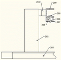
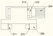
As a further improvement of the utility model, the welding working frame comprises a base and a supporting seat arranged on the base in a sliding manner, two sides of the top end of the supporting seat are respectively provided with a fixed plate, a rotating shaft is arranged between the two fixed plates in a rotating manner, one end of the rotating shaft is fixedly connected with an output shaft of a rotating driving mechanism, a connecting block is fixedly arranged on the rotating shaft, a clamping groove is arranged on the outer side of the connecting block, and a clamping pad capable of adjusting the clamping degree is arranged on the inner side of the bottom end of the clamping groove.
As a further improvement of the utility model, the bottom of the clamping pad is fixed on a stud which penetrates through the bottom end of the clamping groove, one side of the stud is in threaded transmission with a gear, and the gear is fixedly arranged on an output shaft of the pneumatic motor.
As a further improvement of the utility model, an installation plate is arranged on the inner side of the bottom end of the clamping groove, the pneumatic motor is fixedly arranged on the installation plate, the gear is arranged in the box body, an output shaft of the pneumatic motor penetrates through the installation plate and the side wall of the box body, the other end of the pneumatic motor is rotatably connected into the side wall of the other end of the box body, and the gear is fixed on the output shaft of the pneumatic motor and is in threaded transmission connection with the stud.
As a further improvement of the utility model, the bottom ends of the two support columns are fixedly arranged on the ground on the left side and the right side of the base, vertical slide rails are arranged at the front end and the rear end of each support column, vertical screw rods are arranged on the inner sides of the support columns, vertical nuts matched with the vertical screw rods and vertical slide blocks matched with the vertical slide rails and sliding are arranged on the support blocks, the vertical screw rods are in threaded transmission connection with the vertical nuts, the bottom ends of the vertical screw rods are rotatably connected to the fixed blocks, the fixed blocks are fixed on the inner sides of the support columns, and vertical driving mechanisms are arranged at the top ends of the vertical screw rods.
As a further improvement of the utility model, horizontal slide rails are arranged at the front end and the rear end of the cross beam, a horizontal screw rod is arranged at the top end, one end of the horizontal screw rod is rotatably connected with the supporting block, the other end of the horizontal screw rod penetrates through the supporting block to be connected with a horizontal driving mechanism, horizontal slide blocks are arranged inside two sides of the welding equipment, a horizontal nut is arranged on the inner side of the top of the welding equipment, and the horizontal nut is in threaded transmission connection with the horizontal screw rod.
As a further improvement of the present invention, the vertical driving mechanism includes a driving motor and a rotating rod, the other end portion of the rotating rod is rotatably connected to the fixing device, two bevel gears are disposed on the rotating rod, the bevel gears which are matched with the two bevel gears of the vertical driving mechanism to perform gear transmission are respectively fixed at the top ends of the vertical screws, a connector is disposed in the middle of the rotating rod, the connector plays a role in supporting the rotating rod, and the connector is rotatably connected with the rotating rod.
As a further improvement of the utility model, the placing frame is of an L-shaped structure, the rear end of one side of the L shape is provided with a lifting slide block, and the other side of the supporting frame corresponding to the placing frame is provided with a balancing weight.
As a further improvement of the utility model, the pulleys and the rocking wheels are at least provided with 2 groups, and the 2 groups of pulleys and rocking wheels correspond to each other in position.
Compared with the prior art, the utility model has the beneficial effects that: according to the utility model, the two ends of the welding working frame in the sliding direction are respectively provided with the workpiece placing frames, one workpiece placing frame is used for loading, the other workpiece placing frame is used for placing the welded workpieces, the loading and unloading can be electrically lifted, the welding working frame can rotate, the workpieces are turned over in the welding process, and the middle stop work is not needed; the sliding arrangement of the welding working frame, the sliding of the welding equipment in the vertical direction and the sliding of the welding equipment in the horizontal direction jointly realize the three-axis linkage, so that the welding equipment is more automatic; in general, the utility model greatly reduces the labor intensity of workers, saves the overturning step in the welding work, greatly improves the welding efficiency and is suitable for popularization and use in modern factories.
Drawings
The utility model will be further described with reference to the following drawings and detailed description:
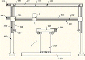
FIG. 1 is a schematic view of a welding apparatus and welding carriage configuration of the present invention;
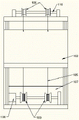
FIG. 2 is a schematic view of a workpiece holding rack;
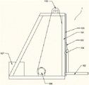
FIG. 3 is a schematic side view of the workpiece holder;
FIG. 4 is a schematic side view of a welding bench;
fig. 5 is a schematic top view of a clamping pad on a welding bench.
In the figure: 1. the device comprises a workpiece placing frame, 101, a supporting frame, 102, a placing frame, 103, a lifting slide rail, 104, a lifting slide block, 105, a steel wire rope, 106, a pulley, 107, a balancing weight, 108, a lifting driving mechanism, 109, a rocking wheel and 110, a rotating rod;
2. the welding device comprises a welding working frame, a base 201, a base 202, a supporting seat 203, a connecting block 204, a rotation driving mechanism 205, a clamping pad 206, a stud 207, a box body 207, a gear 208, a clamping groove 209, a mounting plate 210, a pneumatic motor 211, a fixing plate 212 and a rotating shaft 213;
3. welding equipment, 301, a cross beam, 302, a horizontal sliding rail, 303, a horizontal screw rod, 304, a horizontal driving mechanism, 305, a supporting block, 306, a supporting column, 307, a fixing block, 308, a vertical screw rod, 309, a vertical sliding rail, 310, a driving motor, 311, a rotating rod, 312, a fixing device, 313, a connector and 314, a bevel gear.
It is noted that in the description of the present invention, the terms "center", "upper", "lower", "left", "right", "vertical", "horizontal", "inner", "outer", etc., indicate orientations or positional relationships based on the orientations or positional relationships shown in the drawings, and are only for convenience in describing the present invention and simplifying the description, but do not indicate or imply that the device or element referred to must have a particular orientation, be constructed and operated in a particular orientation, and thus, should not be construed as limiting the present invention. Furthermore, the terms "first," "second," and "third" are used for descriptive purposes only and are not to be construed as indicating or implying relative importance.
In the description of the present invention, it should be noted that, unless otherwise explicitly specified or limited, the terms "mounted," "connected," and "connected" are to be construed broadly, e.g., as meaning either a fixed connection, a removable connection, or an integral connection; can be mechanically or electrically connected; they may be connected directly or indirectly through intervening media, or they may be interconnected between two elements. The specific meanings of the above terms in the present invention can be understood in specific cases to those skilled in the art.
Detailed Description
For better understanding of the technical solutions and advantages of the present invention, the following detailed description of the present invention is provided in conjunction with the accompanying drawings and specific embodiments, it should be understood that the specific embodiments described herein are only for the understanding of the present invention and are not intended to limit the present invention, and all other embodiments obtained by those of ordinary skill in the art without any inventive work are within the scope of the present invention.
Referring to fig. 1 to 5, the automatic welding equipment for large workpieces with automatic loading includes a workpiece placing rack 1, a welding equipment 3 and a welding work rack 2;
the workpiece placing frame 1 comprises a supporting frame 101 and a placing frame 102 arranged outside the supporting frame 101 in a sliding manner, a lifting slide rail 103 is arranged on one side of the supporting frame 101 arranged in a sliding manner with the placing frame 102, a lifting slide block 104 matched with the lifting slide rail 103 for sliding is arranged on the placing frame 102, a pulley 106 is arranged on the top of the supporting frame 101, the pulley 106 is rotatably arranged on the top end of the supporting frame 101 through a rotating rod 110, a lifting driving mechanism 108 is arranged at the bottom of the supporting frame 101, the end part of an output shaft of the lifting driving mechanism 108 is rotatably arranged on the supporting frame 101 through a bearing seat, a rocking wheel 109 is fixedly arranged on the output shaft of the lifting driving mechanism 108, a steel wire rope 105 is arranged on the rocking wheel 109, the other end of the steel wire rope 105 is fixedly arranged on the placing frame 102 through the pulley 106, at least 2 groups of the pulley 106 and the rocking wheel 109 are arranged, the positions of the pulley 106 and the rocking wheel 109 of the 2 groups are corresponding to each other, the placing frame 102 is of an L-shaped structure, the lifting slide block 104 is arranged at the rear end of one side of the L shape, a balancing weight 107 is arranged on the other side of the supporting frame 101 corresponding to the position of the placing frame 102;
Both ends are equipped with horizontal slide rail 302 around crossbeam 301, and the top is equipped with horizontal screw 303, and the one end and the supporting shoe 305 swivelling joint of horizontal screw 303, the other end run through the supporting shoe 305 and are connected with horizontal actuating mechanism 304, and the inside horizontal slider that is equipped with in welding equipment 3's both sides, the inside horizontal nut that is equipped with in welding equipment 3's top, horizontal nut and horizontal screw 303 threaded transmission are connected.
The vertical driving mechanism comprises a driving motor 310 and a rotating rod 311, the other end part of the rotating rod 311 is rotatably connected to a fixing device 312, two bevel gears 314 are arranged on the rotating rod 311, the bevel gears 314 which are matched with the two bevel gears 314 of the vertical driving mechanism to perform gear transmission are respectively fixed at the top ends of the vertical screw rods 308, a connector 313 is arranged in the middle of the rotating rod 311, the connector 313 plays a role in supporting the rotating rod 311, and the connector 313 is rotatably connected with the rotating rod 311.
The bottom end inner side of draw-in groove 209 is equipped with mounting panel 210, is fixed on the mounting panel 210 to be equipped with pneumatic motor 211, and gear 208 sets up in box 207, and the output shaft of pneumatic motor 211 runs through the lateral wall of mounting panel 210 and box 207, and the other end rotates to be connected to in the other end lateral wall of box 207, and gear 208 is fixed on the output shaft of pneumatic motor 211 to be connected with double-screw bolt 206 screw thread transmission.
The two workpiece placing racks 1 are respectively arranged at two ends of the welding work frame 2 in the sliding direction, and the sliding direction of the welding work frame 2 is perpendicular to the sliding direction of the welding equipment 3 on the cross beam 301.
When the welding device is used, a workpiece is placed on the workpiece placing frame 1, the welding working frame 2 slides to the position of the workpiece placing frame 1, then the lifting driving mechanism 108 is started, the steel wire rope 105 pulls the placing frame 102 to lift upwards, when the clamping groove 209 can clamp the workpiece, the welding working frame 2 continuously slides until the clamping groove 209 contacts the workpiece, at the moment, the pneumatic motor 211 is started, the clamping pad 205 clamps the workpiece, then the welding working frame 2 slides, at the moment, the welding device 3 moves in the vertical and horizontal directions under the driving of the vertical driving mechanism and the horizontal driving mechanism 304, when the welding device 3 moves to be in a proper position with the welding position of the workpiece, the welding is started, when the welding is completed, the driving mechanism 204 is rotated to be started, the clamping groove 209 drives the workpiece to rotate together, when the workpiece rotates to the other working surface, the vertical driving mechanism and the horizontal driving mechanism 304 are started to move the welding device, after another working face is welded, the welding working frame 2 is opened in a sliding action, the workpiece placing frame 1 on the other side slides to place the workpiece on the placing frame, the welding working frame slides to another workpiece placing frame to take the workpiece, the operation is repeated, the workpiece can be welded quickly, in the process, the workpiece is turned over automatically, the welding time is saved, the working strength of operators for turning the workpiece is reduced, the workpieces can be automatically put on and off the frame, the working strength is greatly reduced, meanwhile, when one workpiece is welded, another workpiece is placed on the workpiece placing frame to wait for taking the workpiece, the waiting time is saved, and the welding efficiency is greatly improved.
Claims (9)
1. The utility model provides an automatic large-scale work piece automatic weld equipment of loading, its characterized in that: comprises a workpiece placing rack, welding equipment and a welding work frame;
the workpiece placing frame comprises a supporting frame and a placing frame arranged outside the supporting frame in a sliding mode, a lifting slide rail is arranged on the supporting frame, a lifting slide block matched with the lifting slide rail to slide is arranged on the placing frame, a pulley is arranged at the top of the supporting frame, a lifting driving mechanism is arranged at the bottom of the supporting frame, the end portion of an output shaft of the lifting driving mechanism is rotationally arranged on the supporting frame through a bearing seat, a rocking wheel is fixedly arranged on the output shaft of the lifting driving mechanism, a steel wire rope is arranged on the rocking wheel, and the other end of the steel wire rope is fixedly arranged on the placing frame after passing through the pulley;
the welding equipment is arranged on the cross beam in a sliding mode, and two ends of the cross beam are arranged on the supporting columns in a vertically sliding mode through the supporting blocks;
the welding working frame is arranged on the base in a sliding mode, the base is arranged between the two support columns, and a rotatable workpiece clamping structure is arranged at the top end of the welding working frame;
the workpiece placing racks are arranged at two ends of the welding work frame in the sliding direction respectively, and the sliding direction of the welding work frame is perpendicular to the sliding direction of the welding equipment on the cross beam.
2. The automatic welding equipment for the large workpieces capable of being automatically loaded according to claim 1, is characterized in that: the welding working frame comprises a base and a supporting seat arranged on the base in a sliding mode, wherein fixing plates are arranged on two sides of the top end of the supporting seat respectively, a rotating shaft is arranged between the two fixing plates in a rotating mode, one end of the rotating shaft is fixedly connected with an output shaft of a rotating driving mechanism, a connecting block is fixedly arranged on the rotating shaft, a clamping groove is formed in the outer side of the connecting block, and a clamping pad capable of adjusting the clamping degree is arranged on the inner side of the bottom end of the clamping groove.
3. The automatic welding equipment for the large workpieces automatically loaded according to claim 2, is characterized in that: the bottom of the clamping pad is fixed on a stud, the stud penetrates through the bottom end of the clamping groove, one side of the stud is in threaded transmission with a gear, and the gear is fixedly arranged on an output shaft of the pneumatic motor.
4. The automatic welding equipment for the large workpieces capable of being automatically loaded according to claim 3, is characterized in that: the bottom inboard of draw-in groove is equipped with the mounting panel, is fixed to be equipped with on the mounting panel pneumatic motor, the gear sets up in the box, pneumatic motor's output shaft runs through the lateral wall of mounting panel and box, and in the other end rotates the other end lateral wall of being connected to the box, the gear is fixed on pneumatic motor's output shaft, and with double-screw bolt screw thread transmission is connected.
5. The automatic welding equipment for the large workpieces capable of being automatically loaded according to claim 1, is characterized in that: the bottom fixing of two the support column sets up subaerial in the left and right sides of base, both ends are equipped with vertical slide rail around the support column, and the inboard of support column is equipped with vertical screw rod, be equipped with on the supporting shoe with vertical screw rod supporting vertical nut and with the gliding vertical slider of vertical slide rail cooperation, vertical screw rod and vertical nut screw thread transmission are connected, the bottom swivelling joint of vertical screw rod is on the fixed block, the fixed block is fixed in the support column inboard, the top of vertical screw rod is equipped with vertical actuating mechanism.
6. The automatic welding equipment for the large workpieces capable of being automatically loaded according to claim 5, is characterized in that: the welding device comprises a cross beam, wherein horizontal sliding rails are arranged at the front end and the rear end of the cross beam, a horizontal screw rod is arranged at the top end of the cross beam, one end of the horizontal screw rod is rotatably connected with a supporting block, the other end of the horizontal screw rod penetrates through the supporting block to be connected with a horizontal driving mechanism, horizontal sliding blocks are arranged inside two sides of the welding device, a horizontal nut is arranged on the inner side of the top of the welding device, and the horizontal nut is in threaded transmission connection with the horizontal screw rod.
7. The automatic welding equipment for the large workpieces capable of being automatically loaded according to claim 6, is characterized in that: vertical actuating mechanism includes driving motor and dwang, and on another tip swivelling joint of dwang was equipped with two bevel gear on the dwang to fixing device, with two bevel gear collocation of vertical actuating mechanism carry out gear drive's bevel gear and fix respectively the top of vertical screw rod, the middle part of dwang is equipped with the connector, the connector plays the effect that supports the dwang, the connector with the dwang rotates to be connected.
8. The automatic welding equipment for the large workpieces capable of being automatically loaded according to claim 1, is characterized in that: the rack is of an L-shaped structure, a lifting slide block is arranged at the rear end of one side of the L shape, and a balancing weight is arranged on the other side of the supporting frame corresponding to the position of the rack.
9. The automatic welding equipment for the large workpieces capable of being automatically loaded according to claim 1, is characterized in that: the pulley with rock the wheel and set up 2 groups at least, 2 groups's pulley and rock the wheel position and correspond each other.
Priority Applications (1)
| Application Number | Priority Date | Filing Date | Title |
|---|---|---|---|
| CN202121685950.4U CN216177856U (en) | 2021-07-23 | 2021-07-23 | Automatic large-scale work piece automatic weld equipment of loading |
Applications Claiming Priority (1)
| Application Number | Priority Date | Filing Date | Title |
|---|---|---|---|
| CN202121685950.4U CN216177856U (en) | 2021-07-23 | 2021-07-23 | Automatic large-scale work piece automatic weld equipment of loading |
Publications (1)
| Publication Number | Publication Date |
|---|---|
| CN216177856U true CN216177856U (en) | 2022-04-05 |
Family
ID=80895174
Family Applications (1)
| Application Number | Title | Priority Date | Filing Date |
|---|---|---|---|
| CN202121685950.4U Active CN216177856U (en) | 2021-07-23 | 2021-07-23 | Automatic large-scale work piece automatic weld equipment of loading |
Country Status (1)
| Country | Link |
|---|---|
| CN (1) | CN216177856U (en) |
-
2021
- 2021-07-23 CN CN202121685950.4U patent/CN216177856U/en active Active
Similar Documents
| Publication | Publication Date | Title |
|---|---|---|
| CN207681694U (en) | A kind of stifled automatic soldering device of axis | |
| CN211638829U (en) | Straight seam welding machine for welding angle steel and flat steel on civil air defense door frame | |
| CN115255052A (en) | Plate bending equipment for flexible hopper production | |
| CN213470146U (en) | Automobile parts welds dress anchor clamps | |
| CN112719705B (en) | Welding equipment for radiating fin | |
| CN213469921U (en) | Special XY-axis vertical girth welding machine | |
| CN113681303A (en) | Welding production line for cabin short rib | |
| CN212470277U (en) | Prevent fire door production and use door frame welding equipment | |
| CN216177856U (en) | Automatic large-scale work piece automatic weld equipment of loading | |
| CN209811546U (en) | Welding equipment convenient to nimble regulation | |
| CN219617000U (en) | Multi-point welding equipment for machining automobile parts | |
| CN216607720U (en) | Welding equipment for underframe of screw machine | |
| CN216829352U (en) | Aluminium alloy welding machine is used in door and window production | |
| CN217254096U (en) | Electric control clamp for machining automobile welding parts | |
| CN216633176U (en) | High strength steel structure welding set | |
| CN210937628U (en) | Automatic exchange membrane net piece forming machine | |
| CN114161033A (en) | Welding equipment and welding method for underframe of screw machine | |
| CN112538625A (en) | Laser cladding auxiliary device for roller | |
| CN207104155U (en) | Oiling car swash plate components welding frock | |
| CN219402957U (en) | Automatic end plate butt joint and welding device | |
| CN220863093U (en) | Welding equipment for overturning bracket | |
| CN220825603U (en) | Double-station die changing vehicle welding device | |
| CN218341320U (en) | Low-voltage switchgear welding set of easy centre gripping | |
| CN218080903U (en) | Group welding fixture for car coupler seat assembly | |
| CN219189197U (en) | C-type transformer |
Legal Events
| Date | Code | Title | Description |
|---|---|---|---|
| GR01 | Patent grant | ||
| GR01 | Patent grant |