CN115566504B - Automatic cable welding method applied to full-automatic welding device - Google Patents
Automatic cable welding method applied to full-automatic welding device Download PDFInfo
- Publication number
- CN115566504B CN115566504B CN202211512803.6A CN202211512803A CN115566504B CN 115566504 B CN115566504 B CN 115566504B CN 202211512803 A CN202211512803 A CN 202211512803A CN 115566504 B CN115566504 B CN 115566504B
- Authority
- CN
- China
- Prior art keywords
- wire
- inner wire
- rubber
- cable
- plate
- Prior art date
- Legal status (The legal status is an assumption and is not a legal conclusion. Google has not performed a legal analysis and makes no representation as to the accuracy of the status listed.)
- Active
Links
Images


Classifications
-
- H—ELECTRICITY
- H01—ELECTRIC ELEMENTS
- H01R—ELECTRICALLY-CONDUCTIVE CONNECTIONS; STRUCTURAL ASSOCIATIONS OF A PLURALITY OF MUTUALLY-INSULATED ELECTRICAL CONNECTING ELEMENTS; COUPLING DEVICES; CURRENT COLLECTORS
- H01R43/00—Apparatus or processes specially adapted for manufacturing, assembling, maintaining, or repairing of line connectors or current collectors or for joining electric conductors
- H01R43/02—Apparatus or processes specially adapted for manufacturing, assembling, maintaining, or repairing of line connectors or current collectors or for joining electric conductors for soldered or welded connections
- H01R43/0249—Apparatus or processes specially adapted for manufacturing, assembling, maintaining, or repairing of line connectors or current collectors or for joining electric conductors for soldered or welded connections for simultaneous welding or soldering of a plurality of wires to contact elements
-
- H—ELECTRICITY
- H01—ELECTRIC ELEMENTS
- H01R—ELECTRICALLY-CONDUCTIVE CONNECTIONS; STRUCTURAL ASSOCIATIONS OF A PLURALITY OF MUTUALLY-INSULATED ELECTRICAL CONNECTING ELEMENTS; COUPLING DEVICES; CURRENT COLLECTORS
- H01R43/00—Apparatus or processes specially adapted for manufacturing, assembling, maintaining, or repairing of line connectors or current collectors or for joining electric conductors
- H01R43/02—Apparatus or processes specially adapted for manufacturing, assembling, maintaining, or repairing of line connectors or current collectors or for joining electric conductors for soldered or welded connections
- H01R43/0263—Apparatus or processes specially adapted for manufacturing, assembling, maintaining, or repairing of line connectors or current collectors or for joining electric conductors for soldered or welded connections for positioning or holding parts during soldering or welding process
-
- H—ELECTRICITY
- H02—GENERATION; CONVERSION OR DISTRIBUTION OF ELECTRIC POWER
- H02G—INSTALLATION OF ELECTRIC CABLES OR LINES, OR OF COMBINED OPTICAL AND ELECTRIC CABLES OR LINES
- H02G1/00—Methods or apparatus specially adapted for installing, maintaining, repairing or dismantling electric cables or lines
- H02G1/12—Methods or apparatus specially adapted for installing, maintaining, repairing or dismantling electric cables or lines for removing insulation or armouring from cables, e.g. from the end thereof
- H02G1/1202—Methods or apparatus specially adapted for installing, maintaining, repairing or dismantling electric cables or lines for removing insulation or armouring from cables, e.g. from the end thereof by cutting and withdrawing insulation
- H02G1/1248—Machines
- H02G1/1251—Machines the cutting element not rotating about the wire or cable
- H02G1/1253—Machines the cutting element not rotating about the wire or cable making a transverse cut
- H02G1/1256—Machines the cutting element not rotating about the wire or cable making a transverse cut using wire or cable-clamping means
-
- H—ELECTRICITY
- H02—GENERATION; CONVERSION OR DISTRIBUTION OF ELECTRIC POWER
- H02G—INSTALLATION OF ELECTRIC CABLES OR LINES, OR OF COMBINED OPTICAL AND ELECTRIC CABLES OR LINES
- H02G1/00—Methods or apparatus specially adapted for installing, maintaining, repairing or dismantling electric cables or lines
- H02G1/12—Methods or apparatus specially adapted for installing, maintaining, repairing or dismantling electric cables or lines for removing insulation or armouring from cables, e.g. from the end thereof
- H02G1/1273—Methods or apparatus specially adapted for installing, maintaining, repairing or dismantling electric cables or lines for removing insulation or armouring from cables, e.g. from the end thereof by pushing backwards insulation
-
- Y—GENERAL TAGGING OF NEW TECHNOLOGICAL DEVELOPMENTS; GENERAL TAGGING OF CROSS-SECTIONAL TECHNOLOGIES SPANNING OVER SEVERAL SECTIONS OF THE IPC; TECHNICAL SUBJECTS COVERED BY FORMER USPC CROSS-REFERENCE ART COLLECTIONS [XRACs] AND DIGESTS
- Y02—TECHNOLOGIES OR APPLICATIONS FOR MITIGATION OR ADAPTATION AGAINST CLIMATE CHANGE
- Y02W—CLIMATE CHANGE MITIGATION TECHNOLOGIES RELATED TO WASTEWATER TREATMENT OR WASTE MANAGEMENT
- Y02W30/00—Technologies for solid waste management
- Y02W30/50—Reuse, recycling or recovery technologies
- Y02W30/82—Recycling of waste of electrical or electronic equipment [WEEE]
Landscapes
- Engineering & Computer Science (AREA)
- Manufacturing & Machinery (AREA)
- Wire Processing (AREA)
Abstract
The invention discloses a full-automatic cable welding device, which comprises a cable uncoiling mechanism, a cable feeding mechanism, a bus rubber cutting and stripping mechanism, an inner wire arranging mechanism, an inner wire rubber cutting and stripping mechanism and an element feeding and welding mechanism, wherein the cable feeding mechanism is arranged on the cable feeding mechanism; the bus rubber cutting and stripping mechanism comprises a cable guide channel, a bus clamping assembly, a bus rubber ring cutting assembly, a bus cutting assembly and a bus rubber separating and pressing assembly; the inner wire arranging mechanism comprises an inner wire fixing and arranging plate, a wire twisting plate and an inner wire sequencing and adjusting assembly; the inner wire rubber cutting and stripping mechanism comprises an inner wire rubber separating and pressing plate, an inner wire rubber ring cutting assembly and an inner wire cutting assembly; the element feeding and welding mechanism comprises an element automatic feeding assembly and an automatic positioning and welding assembly. The automatic wire feeding device can realize the full-automatic operation of automatic feeding of the wire cables and electronic elements, automatic peeling and cutting of the wire cables, automatic sequential arrangement of inner wires, automatic welding and the like, and greatly improves the operation efficiency, thereby improving the production efficiency, and reducing the labor intensity of workers and the production cost of enterprises.
Description
Technical Field
The invention relates to the field of automatic welding equipment, in particular to an automatic cable welding method applied to a full-automatic welding device.
Background
With the rapid development of automation technology and the electronics industry, more and more electronic devices are being used in various industrial technology fields. Electronic components, particularly circuit boards, adapters, etc., often need to be soldered to external cables to achieve local circuit assembly, so that the electronic components can be provided to procured enterprises as finished components to form more complex circuit modules as constituent components. And in the welding process of the cable, the rubber at the end part is stripped to be an essential procedure.
At present, the wire stripping process adopted in industry mainly comprises three modes of mechanical type, electric heating type and laser type. Mechanically cutting and stripping the sheath of the cable by controlling a sharp blade; the electric heating type reduces the sharpness of the blade on the basis of the mechanical type, and simultaneously controls the cutting and stripping blade to melt and vaporize the sheath material at a certain temperature to realize the cutting and stripping of the cable sheath; in the laser ablation method, as the polymer absorbs the light energy and evaporates, all material on the wire is removed. Because the end part of the cable has certain flexibility, the inner wires are usually multiple, after the outermost rubber is peeled off, the multiple inner wires can be naturally loosened randomly, and each inner wire (usually distinguished by inner rubber with different colors) meets the requirement of a wire sequence with the welding of an electronic element, so that the rubber peeling of the cable and the welding of the electronic element are mainly manually operated, and a partial automatic wire stripping machine is also arranged on the market and is used for mechanical operation of the rubber peeling of the cable.
The main problems of manual operation are: with the reduction of the diameter of the wire, the thickness of the cable rubber and the diameter of the inner wire core are reduced, and manual operation needs higher operation experience and technique to reduce or eliminate conductor damage and wire deformation as much as possible, and has high working strength and low efficiency; the traditional automatic wire stripper has the main problems that when the inner layer skin of a multi-core wire cable is sheared: the inner core wires of the multi-core wire cable are arranged in a triangular stack mode under the wrapping of the outer insulating layer, the conditions that the inner layer is adhered to the inner layer wires or the inner layer is incomplete when the inner layer is cut by the upper cutter and the lower cutter and the like often occur, and manual intervention is needed for secondary stripping.
Aiming at the problems that the semi-automatic/automatic production of stripping cables (especially superfine cables) is realized, the requirement of batch production is met, the quality control of welding spots is difficult and the like due to small size and various types of assemblies to be welded is solved by improving and optimizing the stripping process of each insulating layer of the cables, selecting a reasonable stripping process and reducing or eliminating conductor damage and conductor deformation in the conventional low-efficiency manual production mode.
Disclosure of Invention
The invention aims to solve the technical problem of providing an automatic cable welding method applied to a full-automatic welding device, which replaces the existing manual welding operation mode, has full-automatic operations of automatic feeding of cables and electronic elements, automatic peeling and cutting of cables, automatic sequential arrangement of internal wires, automatic welding and the like, and improves the welding operation efficiency.
In order to solve the technical problems, the invention adopts a technical scheme that: provide for
A cable automatic welding method applied to a full-automatic welding device comprises a cable uncoiling mechanism and a cable feeding mechanism, wherein a bus rubber cutting and stripping mechanism, an inner wire arranging mechanism, an inner wire rubber cutting and stripping mechanism and an element feeding and welding mechanism are sequentially arranged on one side, away from the cable uncoiling mechanism, of the cable feeding mechanism;
the bus rubber cutting and stripping mechanism comprises a first base, a first support and a second support, the first support and the second support are respectively arranged at the top of the first base and can move relatively, a cable guide channel connected with a cable feeding mechanism is arranged at the top of the first support, a bus clamping assembly, a bus rubber ring cutting assembly and a bus cutting assembly are respectively arranged on the cable guide channel, and a bus rubber separating and pressing assembly is arranged at the top of the second support;
the inner wire arranging mechanism comprises a third support and a fourth support, an inner wire fixing and arranging plate is fixedly arranged at the top of the third support, a liftable inner wire auxiliary arranging plate is arranged on one side, close to the bus rubber cutting and stripping mechanism, of the inner wire fixing and arranging plate, and a plurality of inner wire sub-embedding pipes distributed in parallel are movably embedded in the top surfaces of the inner wire fixing and arranging plate and the inner wire auxiliary arranging plate;
the top of the fourth bracket is provided with a lifting mounting plate, the top surface of the mounting plate is provided with a wire twisting plate which can horizontally reciprocate and is positioned right above the inner wire fixing and arranging plate, and the wire twisting plate is provided with an inner wire sequencing and adjusting assembly;
the inner wire rubber cutting and stripping mechanism comprises a second base, an inner wire rubber separating and pressing plate, an inner wire rubber circular cutting assembly and an inner wire cutting assembly, wherein the inner wire rubber separating and pressing plate is arranged above the second base and is positioned on one side, away from the inner wire auxiliary wire arranging plate, of the inner wire fixing wire arranging plate, the inner wire rubber circular cutting assembly and the inner wire cutting assembly are respectively arranged on the wire twisting plate and are positioned right above the inner wire rubber separating and pressing plate, and the inner wire rubber separating and pressing plate can horizontally move and vertically lift;
the component feeding and welding mechanism comprises a fifth support and a workbench fixed to the top of the fifth support, a component automatic feeding assembly is arranged on the top surface of the workbench, and an automatic positioning and welding assembly is arranged above the discharging end of the component automatic feeding device.
Furthermore, a first push-pull cylinder and a first guide rail are fixedly mounted on the top surface of the first base, and the first support is fixedly connected to the output shaft end of the first push-pull cylinder and is slidably mounted on the first guide rail.
Furthermore, a bus rubber link knife edge and a bus cutting knife edge are respectively arranged on the cable guide channel in a penetrating mode, the bus rubber ring cutting assembly comprises a first upper support fixedly arranged at the top of the cable guide channel and a first lower support arranged at the bottom of the cable guide channel, a first upper ring cutting cylinder is fixedly arranged at the top of the first upper support, a first upper ring cutting blade located right above the bus rubber link knife edge is fixedly connected to the bottom output end of the first upper ring cutting cylinder, a first lower ring cutting cylinder is fixedly arranged at the bottom of the first lower support, and a first lower ring cutting blade located right below the bus rubber link knife edge is fixedly connected to the top output end of the first lower ring cutting cylinder;
subassembly is decided to generating line is including fixed the second upper bracket that sets up in cable guide way top, the fixed cylinder of deciding that is provided with in top of second upper bracket, the first bottom output end fixedly connected with that decides the cylinder is located the generating line and decides the first blade of deciding directly over the edge of a knife.
Furthermore, the bus clamping assembly comprises a sixth upper support fixedly arranged at the top of the cable guide channel, a second pressing cylinder is fixedly arranged at the top of the sixth upper support, and a second pressing plate movably buckled in the top of the cable guide channel is fixedly connected to the bottom output end of the second pressing cylinder;
the bus rubber separation pressing assembly comprises a third upper support fixedly arranged at the top of the second support, a first pressing cylinder is fixedly arranged on the third upper support, and a first pressing plate movably buckled in the top of the cable guide channel is fixedly connected to the bottom output end of the first pressing cylinder.
Furthermore, a first lifting cylinder is fixedly arranged on one side of the top surface of the second base, a first lifting support is fixedly connected to the top output end of the first lifting cylinder, the internal wire auxiliary wire arranging plate is fixedly connected to the top of the first lifting support, and two side ends of the internal wire auxiliary wire arranging plate are slidably embedded in side plates on two sides of the third support.
Furthermore, the opening has been seted up at the middle part of the fixed winding displacement board of interior wire, still fixedly connected with matches the interior auxiliary winding displacement subplate of interior wire that is located the opening on one side of the top surface of first lifting support.
Furthermore, the inner wire embedding pipe is of a U-shaped section pipeline structure with an opening at the top, the bottom of the inner wire embedding pipe is integrally provided with a splicing column, and the top surface of the inner wire fixing wire arranging plate is provided with a splicing hole matched with the splicing column.
Furthermore, the top surface of the fourth support is provided with a third lifting cylinder, the mounting plate is fixedly connected to the top output shaft end of the third lifting cylinder, the top surface of the mounting plate is fixedly provided with a wire twisting cylinder, and the wire twisting plate and the inner wire fixing wire arranging plate are arranged in parallel and fixedly connected to the output shaft end of the wire twisting cylinder.
Furthermore, the interior line sequencing adjusting assembly comprises a fourth upper support fixedly arranged on the top surface of the thread rolling plate, first push-pull air cylinders fixedly arranged on two sides of the top surface of the fourth upper support, and a camera fixedly embedded in the bottom surface of the interior line fixed thread arranging plate, wherein the bottom output end of each first push-pull air cylinder is connected with a lifting supporting plate positioned in the fourth upper support, a first linear driving mechanism is arranged on the top surface of each lifting supporting plate, and a pneumatic gripper positioned on one side of each lifting supporting plate and positioned right above the interior line auxiliary thread arranging plate is fixedly arranged at the power output end of each first linear driving mechanism.
Furthermore, a second push-pull cylinder and a second guide rail are fixedly arranged on the top surface of the second base, an output rod end of the second push-pull cylinder is fixedly connected with a positioning plate which is slidably embedded at the top of the second guide rail, a second lifting cylinder is fixedly arranged at the top of the positioning plate, a top output end of the second lifting cylinder is fixedly connected with a second lifting support, two side ends of the second lifting support are slidably embedded in side plates on two sides of a third support, and an interior thread rubber separation pressing plate is fixedly connected to the top end of the second lifting support.
Furthermore, an inner wire rubber link knife edge and an inner wire cutting knife edge are respectively arranged on the inner wire rubber separation pressing plate in a penetrating mode, the inner wire rubber ring cutting assembly comprises a fifth upper support fixed to the top surface of the thread rolling plate and a fifth lower support fixed to the bottom surface of the inner wire rubber separation pressing plate, a second upper ring cutting cylinder is fixedly arranged at the top of the fifth upper support, a second upper ring cutting blade movably embedded in the thread rolling plate and located right above the inner wire rubber link knife edge is fixedly connected to the bottom output end of the second upper ring cutting cylinder, a second lower ring cutting cylinder is fixedly arranged on the fifth lower support, and a second lower ring cutting blade movably embedded in the thread rolling plate and located right below the inner wire rubber link knife edge is fixedly connected to the top output end of the second lower ring cutting cylinder;
the assembly is decided to interior line includes that fixed setting decides the cylinder in the second at fifth upper bracket top, the bottom output end fixedly connected with that the cylinder was decided to the second is located the interior line and decides the blade directly over the edge of a knife.
Furthermore, the automatic element feeding assembly comprises a storage box and a feeding cylinder which are fixedly arranged on the top surface of the workbench respectively, and an output shaft of the feeding cylinder is fixedly connected with a feeding support box which movably penetrates through the bottom of the storage box;
the automatic positioning and welding assembly comprises a movable support movably arranged on the top surface of a workbench, a second linear driving mechanism is arranged at the top of the movable support, a welding gun positioned right above a feeding support box is fixedly arranged at the power output end of the second linear driving mechanism, movable push plates are fixedly arranged on the two sides of the movable support respectively, push rods which are movably contacted with the side surfaces of the movable push plates are fixedly arranged on the outer wall of the feeding support box, guide rods are fixedly arranged on the side surfaces of the movable push plates, reset springs are sleeved on the outer side of the guide rods, and one ends of the reset springs are fixedly connected with the movable push plates, and the other ends of the reset springs are fixedly connected with the workbench.
The automatic welding method of the cable applied to the automatic welding device of the cable is further provided, and comprises the following steps:
s1, placing a cable reel to be welded on a cable uncoiling mechanism, enabling the free end of the cable reel to penetrate through a cable feeding mechanism and be led into a cable guide channel of a bus rubber cutting and stripping mechanism, placing a certain number of electronic components to be welded into an automatic component feeding device, and starting a full-automatic cable welding device;
s2, the cable feeding mechanism feeds the cable to a preset distance and then stops working;
s3, starting a bus rubber ring cutting assembly, cutting and resetting an outer rubber layer at the free end of the cable, starting a bus rubber separating and pressing assembly, clamping the end outer rubber layer at the free end of the cable which is ring-cut, starting a bus clamping assembly, clamping the outer rubber layer at the reserved end of the cable, horizontally moving a cable guide channel for a certain distance along the opposite direction of cable feeding, enabling the end outer rubber layer which is ring-cut to slide for a corresponding distance from an inner wire, further enabling the inner wire to be partially exposed, starting a bus cutting assembly, cutting the outer rubber layer which slides off from the inner wire into two sections, resetting the outer rubber layer of the small section to be reserved at the tail end of the inner wire, and resetting the bus clamping assembly and the bus rubber separating and pressing assembly;
s4, starting the cable feeding mechanism, continuously feeding the cable forward for a certain length until the outer layer rubber staying at the tail end of the inner wire is positioned on one side, away from the inner wire fixed wiring board, of the inner wire rubber separation pressing plate, and stopping working of the cable feeding mechanism;
s5, the inner wire arranging mechanism starts to work, the mounting plate is driven to horizontally and longitudinally reciprocate along the direction vertical to the feeding direction of the cable and gradually descend to a preset height, the wire twisting plate respectively twists a plurality of inner wires into corresponding inner wire sub-embedding pipes, and then the wire twisting plate ascends and resets;
s6, the inner wire sequencing adjusting assembly acquires and identifies each inner wire embedded in the inner wire sub-embedding pipe according to the color of the inner wire, compares the inner wire with a standard color sequence preset by the system for analysis, adjusts the position of the inner wire sub-embedding pipe to enable the color sequencing of the inner wires embedded in the inner wire sub-embedding pipe to be the same as the standard color sequence preset by the system, and resets;
s7, the thread rolling plate descends again, the inner-layer rubber of the end part of the inner wire, which is annularly cut at the free end of the inner wire, is pressed on the top surface of the inner-wire rubber separation pressing plate, the inner-layer rubber of the remaining end of the inner wire is pressed in the inner-wire fixed winding displacement plate, the inner-wire rubber separation pressing plate moves horizontally for a certain distance to one side far away from the inner-wire fixed winding displacement plate, the inner-layer rubber of the annularly cut end part slides for a corresponding distance from the wire core, the wire core is partially exposed, the inner-wire cutting assembly is started, the inner-layer rubber slipping from the wire core is cut into two sections and then reset, the small sections of the inner-layer rubber are retained at the tail end of the wire core, and the thread rolling plate ascends again and resets;
s8, the inner wire rubber separation pressing plate descends by a certain height, the element automatic feeding assembly pushes an electronic element to be welded to the upper part of the inner wire rubber separation pressing plate and the lower part of the free end of the inner wire, meanwhile, the automatic positioning welding assembly is pushed to the upper part of the free end of the inner wire, the automatic positioning welding assembly welds the exposed part of each wire core with the corresponding welding point on the electronic element one by one, and after welding is completed, the element automatic feeding assembly and the automatic positioning welding assembly reset in sequence;
s9, the bus cutting assembly is started again, the bus is cut, the inner wire rubber separation pressing plate is reset to ascend by a certain height, the welded electronic element is lifted, each inner wire is moved out of the inner wire embedded pipe, and the electronic element welded with the cable is removed from the equipment through a manipulator;
and S10, repeating the steps S2 to S9 to complete the welding work of the next electronic element and the next section of cable.
The invention has the following beneficial effects:
1. according to the invention, by arranging the cable uncoiling mechanism, the cable feeding mechanism, the bus rubber cutting and stripping mechanism, the inner wire arranging mechanism, the inner wire rubber cutting and stripping mechanism and the element feeding and welding mechanism, the full-automatic operation of automatic feeding of cables and electronic elements, automatic peeling and cutting of cables, automatic sequential arrangement and automatic welding of inner wires and the like can be realized, manual welding operation is replaced, and the welding operation efficiency is greatly improved, so that the production efficiency is improved, and the labor intensity of workers and the production cost of enterprises are reduced;
2. according to the bus rubber stripping mechanism, the outer rubber is stripped by adopting the processes of outer rubber ring cutting, incomplete stretching stripping and cutting off the outer rubber stripped outside the end part of the inner wire, the inner wire is sequenced in a preset welding position by adopting the color identification and positioning adjustment modes by arranging the inner wire arranging mechanism, and the inner rubber ring cutting, incomplete stretching stripping and cutting off the inner rubber stripped outside the end part of the wire core and the residual outer rubber are arranged by arranging the inner wire rubber stripping mechanism, so that the stripping of the inner rubber is completed, the exposure of the welding part of the wire core is realized, the problem of incomplete ring cutting caused by gathering and stacking in the prior art is effectively solved, and the problem of low efficiency caused by manual inner wire sequencing is solved;
3. the invention adopts the modes of accurate positioning of electronic elements, fixed-length feeding and cutting of cables and the like, and is matched with an automatic welding process, so that the consistency of the product quality can be ensured while the production efficiency is improved, the integral quality and the market competitiveness of the product can be favorably improved, and better economic benefit is brought to production enterprises.
Drawings
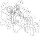
FIG. 1 is a schematic perspective view of the present invention;
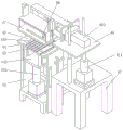
FIG. 2 is a second schematic perspective view of the present invention;
FIG. 3 is a schematic perspective view of the bus bar rubber cutting and stripping mechanism;
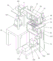
fig. 4 is a schematic perspective view of the inner wire arranging mechanism;
fig. 5 is a schematic perspective view of the inner thread rubber cutting and peeling mechanism;
fig. 6 is a schematic perspective structure view of each component on the wire twisting plate;
FIG. 7 is a schematic perspective view of the inner wire embedding tube;
fig. 8 is a schematic perspective view of the inner wire sequencing adjustment assembly;
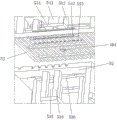
FIG. 9 is a schematic perspective view of the component feeding and welding mechanism;
fig. 10 is a second schematic perspective view of the component feeding and welding mechanism;
fig. 11 is an enlarged schematic view of a portion a in fig. 9.
In the figure: 1 cable unwinding mechanism, 2 cable feeding mechanisms, 3 bus rubber cutting and stripping mechanisms, 31 first base, 311 first push-pull air cylinder, 312 first guide rail, 32 first support, 33 second support, 34 cable guide channel, 35 bus rubber ring cutting assembly, 351 first upper support, 352 first lower support, 353 first upper ring cutting air cylinder, 354 first upper ring cutting blade, 355 first lower ring cutting air cylinder, 356 first lower ring cutting blade, 36 bus cutting assembly, 361 second upper support, 362 first cutting air cylinder, 363 first cutting blade, 37 bus rubber separating and pressing assembly, 371 third upper support, 372 first pressing air cylinder, 373 first pressing plate, 38 bus clamping assembly, 381 sixth upper support, 382 second pressing air cylinder, 383 second pressing plate, 4 interior wiring mechanism, 41 third support, 42 fourth support, 421 third lifting air cylinder, 43 fixed wiring board 44 auxiliary inner wire arranging plate, 441 first lifting cylinder, 442 first lifting bracket, 443 inner wire auxiliary inner wire arranging plate, 45 inner wire embedding tube, 451 splicing column, 46 mounting plate, 461 wire twisting cylinder, 47 wire twisting plate, 48 inner wire arranging adjusting component, 481 fourth upper bracket, 482 first push-pull cylinder, 483 first linear driving mechanism, 484 camera, 485 pneumatic gripper, 486 lifting supporting plate, 5 inner wire rubber cutting mechanism, 51 second base, 511 second push-pull cylinder, 512 second guide rail, 513 positioning plate, 514 second lifting cylinder, 515 second lifting bracket, 52 inner wire rubber separating and pressing plate, 53 inner wire rubber ring cutting component, 531 fifth upper bracket, 532 second upper ring cutting cylinder, 533 second upper ring cutting blade, 534 fifth lower bracket, 535 second lower ring cutting cylinder, 536 second lower ring cutting blade, 54 inner wire cutting component, 541 second cutting cylinder, 542 second cutting blade, the automatic welding machine comprises a 6-component feeding and welding mechanism, a 61 fifth bracket, a 62 workbench, a 63-component automatic feeding assembly, a 631 storage box, a 632 feeding air cylinder, a 633 feeding tray box, a 634 push rod, a 64 automatic positioning and welding assembly, a 641 moving bracket, a 642 second linear driving mechanism, a 643 welding gun, an 644 movable push plate, a 645 guide rod, a 646 return spring, 100 electronic components and a 110-component box.
Detailed Description
The following detailed description of the preferred embodiments of the present invention, taken in conjunction with the accompanying drawings, will make the advantages and features of the invention easier to understand by those skilled in the art, and thus will clearly and clearly define the scope of the invention.
Referring to fig. 1 and 2, an automatic cable welding method applied to a full-automatic welding device includes a cable unwinding mechanism 1 and a cable feeding mechanism 2, wherein a bus rubber cutting and stripping mechanism 3, an inner wire winding displacement mechanism 4, an inner wire rubber cutting and stripping mechanism 5, and an element feeding and welding mechanism 6 are sequentially disposed on one side of the cable feeding mechanism 2 away from the cable unwinding mechanism 1. A cable for fixed length cuts sets up on cable unwinding mechanism 1, and the free section of cable is worn to establish and is surely shelled the mechanism 3 with the generating line rubber and give by 2 fixed length step-by-step of cable feed mechanism. Cable unwinding mechanism 1 adopts current cable pay off rack, and cable feed mechanism 2 adopts current to roll-type cable conveyor, is prior art, and concrete structure and theory of operation here do not do the perusal.
As shown in fig. 3, the bus bar peeling and cutting mechanism 3 includes a first base 31, a first support 32 and a second support 33 respectively disposed on top of the first base 31 and capable of moving relatively. In this embodiment, a first push-pull cylinder 311 and a first guide rail 312 are fixedly mounted on the top surface of the first base 31, the telescopic direction of the output shaft of the first push-pull cylinder 311 is set along the feeding direction of the cable (hereinafter, horizontal), and the air inlet and outlet of the first push-pull cylinder 311 are connected with an external air source through a pipeline, and logic control is implemented through a controller arranged on the device, so as to implement corresponding telescopic work (pneumatic control belongs to the prior art, and is not described herein, and also applies to each cylinder below). The first bracket 32 is fixedly connected to an output shaft end of the first push-pull cylinder 311 and is slidably mounted on the first guide rail 312, the second bracket 33 is fixedly arranged at one end of the top surface of the first base 31, and the first bracket 32 can be pushed to be close to or far away from the second bracket 33 through the telescopic operation of the first push-pull cylinder 311.
The top of the first bracket 32 is provided with a cable guide channel 34 which engages with the cable feeding mechanism 2. In this embodiment, the cable guide channel 34 is a bar-shaped plate structure with a through hole at the middle, and is fixed on the top surface of the first bracket 32 by bolt connection or welding, the diameter of the through hole is determined according to the outer diameter of the cable, and is slightly larger than the outer diameter of the cable, so that the cable can smoothly pass through the through hole. The bus clamping assembly 38, the bus rubber sheet circular cutting assembly 35 and the bus cutting assembly 36 are arranged on the cable guide channel 34 along the cable feeding direction respectively, the bus rubber sheet separating and pressing assembly 37 is arranged at the top of the second support 33, the cable entering the cable guide channel 34 completes circular cutting of the bus rubber sheet through the bus rubber sheet circular cutting assembly 35, partial stripping of the cut bus rubber sheet is completed under the matching of the bus rubber sheet separating and pressing assembly 37, and the bus cutting assembly 36 completes cutting of the free end of the cut bus.
Specifically, the edge of a knife is decided to last having run through respectively of cable guiding channel 34 and having seted up generating line rubber link edge of a knife and generating line, generating line rubber ring cuts subassembly 35 including fixed setting in the first upper bracket 351 at cable guiding channel 34 top and setting in the first lower carriage 352 of cable guiding channel 34 bottom, the fixed first cylinder 353 that cuts of going up of being provided with in top of first upper bracket 351, the bottom output end fixedly connected with who first goes up the ring and cuts the cylinder 353 is located the first ring cutter piece 354 that the generating line rubber link edge of a knife is directly over to the first output end of going up the ring, the fixed first cylinder 355 that cuts of being provided with in bottom of first lower carriage 352, the top output end fixedly connected with who cuts the cylinder 355 first ring cutter piece 356 that is located under the generating line rubber link edge of a knife. When the free section of the cable is fed to a length within a preset range by the cable feeding mechanism 2, the first upper ring cutting cylinder 353 and the first lower ring cutting cylinder 355 are started to work simultaneously, the first upper ring cutting cylinder 353 pushes the first upper ring cutting blade 354 to move downwards and enter the bus rubber link cutting edge, and the first lower ring cutting cylinder 355 pushes the first lower ring cutting blade 356 to move upwards and enter the bus rubber link cutting edge. In this embodiment, the first upper ring cutting blade 354 and the first lower ring cutting blade 356 are both semi-circular arc blades, and after entering the bus rubber link edge, the two blades respectively act on the bus rubber (cable outer rubber) to realize the ring cutting of the bus rubber.
The bus rubber sheet separating and pressing assembly 37 comprises a third upper support 371 fixedly arranged at the top of the second support 33, a first pressing cylinder 372 is fixedly arranged on the third upper support 371, and a first pressing plate 373 movably buckled in the top of the cable guide channel 34 is fixedly connected to the bottom output end of the first pressing cylinder 372. The bus bar clamping assembly 38 includes a sixth upper bracket 381 fixedly disposed on the top of the cable guide channel 34, a second pressing cylinder 382 is fixedly disposed on the top of the sixth upper bracket 381, and a second pressing plate 383 movably buckled in the top of the cable guide channel 34 is fixedly connected to a bottom output end of the second pressing cylinder 382. A first notch and a second notch located right below a second pressing plate 383 are arranged on the top surface of the cable guide channel 34 below the first pressing block 373, so that the tops of cable outer layer rubber sheets located at the two notches are exposed, after the bus rubber sheet completes circular cutting operation, the first pressing cylinder 372 and the second pressing cylinder 382 start to work, the first pressing plate 373 is respectively pushed to move downwards and enter the first notch, and the second pressing plate 383 is pushed to enter the second notch, so that two sections of bus rubber sheets after circular cutting are respectively pressed tightly in the cable guide channel 34.
At this time, the first pushing cylinder 311 works reversely, the first support 32 is pulled to be away from the second support 33, the bus clamping assembly 38 is away from the bus rubber separation pressing assembly 37, the cable is retreated for a certain distance (for example, 4/5 of the length of the bus rubber which is cut off circularly) along the direction opposite to the feeding direction of the cable, so that the bus rubber which is cut off circularly at the tail end of the free end of the cable is stripped from the inner wire of the cable, the bus rubber with a certain length is reserved at the tail end of the inner wire, and the tail end of the inner wire is prevented from being diverged; then first promotion cylinder 311 forward work, promote first support 32 and be close to second support 33 and reset, the position that cuts of subassembly 36 is decided to the interior line end position of cable this moment, and the sword mouth is decided to the generating line promptly.
As shown in fig. 4 to 6, the internal wire arranging mechanism 4 includes a third bracket 41 and a fourth bracket 42, an internal wire fixing and arranging plate 43 is fixedly disposed on the top of the third bracket 41, and a liftable internal wire auxiliary arranging plate 44 is disposed on one side of the internal wire fixing and arranging plate 43 close to the bus rubber stripping and cutting mechanism 3. Specifically, a second base 51 is arranged at the bottom of the inner side of the third bracket 41, a first lifting cylinder 441 in the output shaft direction is fixedly arranged on one side of the top surface of the second base 51, a first lifting bracket 442 is fixedly connected to the output end of the top of the first lifting cylinder 441, the internal wire auxiliary wire arranging plate 44 is fixedly connected to the top of the first lifting bracket 442, and the internal wire auxiliary wire arranging plate 44 can be driven by the first lifting cylinder 441 to lift; slide bars are fixedly arranged at two side ends of the inner wire auxiliary winding displacement plate 44, guide grooves which are vertically arranged are formed in two side plates of the third support 41, and the slide bars are movably embedded in the guide grooves to guide and limit the lifting of the first lifting support 442 and the inner wire auxiliary winding displacement plate 44. When the auxiliary inner wire arranging plate 44 is located at the highest position, the top surface of the auxiliary inner wire arranging plate 44 and the top surface of the fixed inner wire arranging plate 43 are located in the same horizontal plane and are not higher than the top surface of the second bracket 33, so that the cable sent out from the cable guide channel 34 can smoothly fall on the top surfaces of the auxiliary inner wire arranging plate 44 and the fixed inner wire arranging plate 43. The cable that the bus rubber is peeled off and cut is sent forward a certain length by the cable feeding mechanism 2 continuously, until the outer rubber that stops at the end of the inner wire is located at one side of the inner wire rubber separation pressing plate 52 far away from the inner wire fixed winding displacement plate 43, the cable feeding mechanism 2 stops working temporarily, at this moment, the inner wires exposed outside are all located on the inner wire auxiliary winding displacement plate 44, the inner wire fixed winding displacement plate 43 and the top surface completely. Preferably, an opening is formed in the middle of the inner wire fixing and arranging plate 43, an inner wire auxiliary and arranging plate 443 located in the opening and matching with the contour of the opening is further fixedly connected to one side of the top surface of the first lifting bracket 442, and the top surface of the inner wire auxiliary and arranging plate 443 is also located in the same horizontal plane as the top surface of the inner wire auxiliary and arranging plate 44.
A plurality of inner wire embedded tubes 45 which are distributed in parallel are movably embedded in the top surfaces of the inner wire fixing wire arranging plate 43 and the inner wire auxiliary wire arranging plate 44. Specifically, as shown in fig. 7, the inner wire embedding sub-tube 45 is a U-shaped cross-section tube structure with an open top, the inner width of the tube is equal to the outer diameter of the inner wire of the cable, the length of the tube is equal to the sum of the widths of the inner wire auxiliary winding displacement plate 44 and the inner wire fixing winding displacement plate 43 in the cable feeding direction, U-shaped grooves matched with the outer shapes of the inner wire embedding sub-tube 45 are also formed on the top surfaces of the inner wire auxiliary winding displacement plate 44 and the inner wire fixing winding displacement plate 43, so that the inner wire embedding sub-tube 45 can be embedded in each U-shaped groove correspondingly, and the top surface of the inner wire embedding sub-tube 45 is flush with the top surface of the inner wire auxiliary winding displacement plate 44. Preferably, the bottom of the inner wire sub-embedded pipe 45 is integrally provided with the plug column 451, the top surface of the inner wire fixing wire arranging plate 43 is provided with the plug hole matched with the plug column 451, and through the plug fit of the plug column 451 and the plug hole, the inner wire sub-embedded pipe 45 can be accurately positioned in the U-shaped groove, the plug reliability can be enhanced, and the inner wire sub-embedded pipe 45 is prevented from easily falling off from the U-shaped groove. In this embodiment, a cable having six inner wires is taken as an example to illustrate the structural composition and the operation principle of the device, the colors of the six inner wires are respectively set to red, green, blue, yellow, black and white, and the welding on the electronic component 100 is completed in this order; the quantity that interior line divides the embedded pipe 45 is the same with the quantity of interior line, and the quantity that the U type groove then divides the embedded pipe 45 of interior line more than one at least to satisfy the needs that follow-up interior line sequence was adjusted, in this embodiment, interior line divides the embedded pipe 45 to set up to 7, and the quantity in U type groove is 7, and one of them is located the U type groove (hereinafter referred to as the transfer U type groove) in the outside and all the other 6U type groove's distance is far away, in order to avoid interior line to get into this U type inslot.
The top surface of the mounting plate 46 is fixedly provided with a thread rolling cylinder 461, an output shaft of the thread rolling cylinder 461 horizontally faces the side where the inner thread fixing and arranging plate 43 is located, the top surface of the mounting plate 46 is provided with a thread rolling plate 47 which can horizontally reciprocate and is located right above the inner thread fixing and arranging plate 43, the thread rolling plate 47 and the inner thread fixing and arranging plate 43 are arranged in parallel and fixedly connected to an output shaft end of the thread rolling cylinder 461, and the thread rolling plate 47 can be driven to horizontally and longitudinally reciprocate through the reciprocating telescopic action of the thread rolling cylinder 461. The top surface of the thread rolling plate 47 is fixedly provided with at least one guide plate, the top surface of the mounting plate 46 is fixedly provided with a vertical plate, the vertical plate is provided with a guide hole matched with the guide plate, and the guide plate is movably inserted into the guide hole to guide the horizontal movement of the thread rolling plate 47.
When the third lifting cylinder 421 works in the reverse direction, the mounting plate 46 is driven to descend, and then the thread rolling plate 47 descends synchronously, so that the bottom surface of the thread rolling plate 47 can be in contact with the inner threads on the top surface of the inner thread fixing and arranging plate 43, in the descending process of the thread rolling plate 47, the thread rolling cylinder 461 drives the thread rolling plate 47 to horizontally reciprocate, after the bottom surface of the thread rolling plate 47 is in contact with rubber of the inner threads, a plurality of inner threads can be arranged in an open manner through a rubbing operation (the tail end of the cable is in a free state, and both ends of the exposed inner threads are in a bundle state), each inner thread is pressed into the corresponding inner thread embedding inner embedding tube 45 through repeated rubbing and extrusion actions (the depth of each inner embedding tube 45 satisfies the embedding of one inner thread at most, and after one inner embedding tube is embedded into a certain distributing tube 45, the rest inner threads can only be pressed into the rest distributing tubes 45), and accordingly, the first dispersed arrangement of the inner threads is realized. Preferably, the bottom surface of the wire twisting plate 47 is provided with a wavy rubber layer, so that the rubber of the inner wire is prevented from being worn by the bottom surface of the wire twisting plate 47 in the rubbing process, the friction force between the bottom surface of the wire twisting plate 47 and the rubber of the inner wire can be enhanced, and the effect of pressing the inner wire into the inner wire embedding tube 45 is enhanced.
As shown in fig. 4 and 5, the thread twisting plates 47 are respectively provided with an inner thread sequencing adjustment assembly 48. As shown in fig. 6 and 8, the internal wire sequencing adjustment assembly 48 includes a fourth upper rack 481 fixedly disposed on the top surface of the wire twisting board 47, first push-pull air cylinders 482 fixedly disposed on both sides of the top surface of the fourth upper rack 481, and a camera 484 fixedly embedded in the bottom surface of the internal wire fixed wire arranging board 43, wherein the output end of the bottom of the first push-pull air cylinder 482 is connected to a lifting support plate 486 positioned in the fourth upper rack 481. Set up the through-hole of vertical setting on the both sides lateral wall of fourth upper bracket 481, the fixed connecting plate that is provided with in both ends of lift layer board 486, the connecting plate activity inlays to be established in the through-hole and fixed connection is at the output axle head of first push-and-pull cylinder 482, and the flexible action of first push-and-pull cylinder 482 through, can drive the lift of lift layer board 486, through the cooperation of connecting plate with the through-hole, can play the guide effect to the vertical lift of lift layer board 486.
The top surface of the lifting supporting plate 486 is provided with a first linear driving mechanism 483, and the power output end of the first linear driving mechanism 483 is fixedly provided with a pneumatic gripper 485 which is positioned on one side of the lifting supporting plate 486 and is positioned right above the inner wire auxiliary wire arranging plate 44. In this embodiment, the first linear driving mechanism 483 employs a ball screw transmission mechanism driven by a servo motor, so as to achieve precise positioning, and the power output end of the first linear driving mechanism reciprocates horizontally and longitudinally (for the prior art, the detailed structure and the working principle thereof are not described herein). The pneumatic gripper 485 can be a universal double-claw miniature pneumatic manipulator with a short-range telescopic function. The thread rolling plate 47 is provided with a through hole which is positioned right above the inner thread auxiliary thread rolling plate 44 and is arranged in parallel with the inner thread auxiliary thread rolling plate 44, and the pneumatic gripper 485 can penetrate through the through hole to the lower part of the bottom surface of the thread rolling plate 47. When the first push-pull air cylinder 482 and the pneumatic gripper 485 are in a contraction state, the clamping part of the pneumatic gripper 485 is positioned in the through hole, and the interference on the kneading operation of the wire kneading plate 47 cannot be generated; when the first push-pull cylinder 482 is in a retracted state and the pneumatic gripper 485 is in an extended state, the gripping portion of the pneumatic gripper 485 is completely located below the bottom surface of the wire twisting plate 47.
After the thread rolling plate 47 finishes the first dispersed arrangement of the inner threads, the thread sequence of the 6 inner threads in the 6 inner thread embedded tubes 45 may be different from the preset welding sequence of the inner threads, so that the inner thread sequence adjusting assembly 48 needs to be used to adjust the thread sequence. Specifically, the third lifting cylinder 421 works in the forward direction, the thread rolling cylinder 461 resets to the initial state and stops working, at this time, the mounting plate 46 and the thread rolling plate 47 synchronously rise to the initial position, the inner thread in the inner thread fixing and arranging plate 43 is subjected to image acquisition through the camera 484, a corresponding color sequence is obtained, the color sequence is transmitted to the control system of the device to be compared and analyzed with a preset standard reference color sequence, and then a corresponding adjustment path is planned (algorithms based on image recognition and path planning are the prior art, and are not described here in detail): if the color of the inner wire in a certain inner wire embedded tube 45 is correct, the position of the inner wire embedded tube 45 is not required to be adjusted, and only the position of the inner wire embedded tube 45 with incorrect position is required to be adjusted; meanwhile, the first lifting cylinder 441 works reversely to drive the inner wire auxiliary winding displacement plate 44 and the inner wire auxiliary winding displacement subplate 443 to move downwards, and at the moment, two ends of the inner wire embedded pipe 45 are respectively removed from the inner wire auxiliary winding displacement plate 44 and the inner wire auxiliary winding displacement subplate 443 and are in a suspension state; the first linear driving mechanism 483 works to drive the power output end of the first linear driving mechanism to move so as to position the pneumatic gripper 485 above the position of the inner wire embedded dividing pipe 45 which needs to be grabbed and moved currently, the first push-pull air cylinder 482 works in the positive direction to push the lifting supporting plate 486 to move downwards, the pneumatic gripper 485 moves downwards to be below the bottom surface of the thread rolling plate 47 and is positioned above the inner wire embedded dividing pipe 45, the clamping part of the pneumatic gripper 485 extends out to clamp the corresponding inner wire embedded dividing pipe 45, then the clamping part of the pneumatic gripper 485 contracts to lift the pneumatic gripper 485 with the inner wire embedded dividing pipe 45 upwards, and the inner wire embedded dividing pipe 45 is moved out of the corresponding U-shaped groove; the first linear driving mechanism 483 works again to drive the power output end of the first linear driving mechanism to move to position the pneumatic gripper 485 above the position of the transit U-shaped groove, the clamping part of the pneumatic gripper 485 extends out again to work, the inner wire embedding sub-pipe 45 is automatically pressed and embedded into the transit U-shaped groove, and the clamping part of the pneumatic gripper 485 releases the inner wire embedding sub-pipe 45 and then contracts; the first linear driving mechanism 483 works again to drive the power output end of the first linear driving mechanism 483 to move to position the pneumatic gripper 485 above the position of the inner wire embedded sub-tube 45 where the inner wire is positioned and the color of the inner wire is matched with that of the inner wire which is supposed to be placed in the current idle U-shaped groove, the clamping part of the pneumatic gripper 485 extends out to clamp the corresponding inner wire embedded sub-tube 45, then the clamping part of the pneumatic gripper 485 contracts, and the pneumatic gripper 485 which clamps the inner wire embedded sub-tube 45 is lifted upwards to move the inner wire embedded sub-tube 45 out of the corresponding U-shaped groove; the first linear driving mechanism 483 works again to drive the power output end of the first linear driving mechanism to move to position the pneumatic gripper 485 above the position of the previous idle U-shaped groove, the clamping part of the pneumatic gripper 485 extends out again to work, the inner wire embedded sub-tube 45 is automatically pressed and embedded into the idle U-shaped groove, the clamping part of the pneumatic gripper 485 releases and contracts the inner wire embedded sub-tube 45, the moved inner wire embedded sub-tube 45 originally located U-shaped groove forms a new idle U-shaped groove, the same process is repeated, secondary sequencing of all inner wires can be completed, and the sequencing is the same as the preset inner wire welding sequencing. After the sequencing process is completed, the first linear driving mechanism 483 and the first push-pull air cylinder 482 drive the pneumatic gripper 485 to reset.
After the inner wire position is adjusted, the inner rubber layer at the end part of the inner wire needs to be peeled off, so that the wire core inside is exposed, and subsequent welding operation can be performed. As shown in fig. 5 and 6, the inner wire rubber cutting and peeling mechanism 5 includes a second base 51, an inner wire rubber separating and pressing plate 52 disposed above the second base 51 and located on one side of the inner wire fixing and arranging plate 43 away from the inner wire auxiliary and arranging plate 44 (i.e., the rear side of the inner wire fixing and arranging plate 43), an inner wire rubber ring cutting assembly 53 and an inner wire cutting assembly 54 respectively disposed on the wire twisting plate 47 and located right above the inner wire rubber separating and pressing plate 52, wherein the inner wire rubber separating and pressing plate 52 can move horizontally and lift vertically.
Specifically, a second push-pull cylinder 511 and a second guide rail 512 are fixedly arranged on the top surface of the second base 51, an output rod end of the second push-pull cylinder 511 is horizontally arranged and fixedly connected with a positioning plate 513 which is slidably embedded at the top of the second guide rail 512, a second lifting cylinder 514 is fixedly arranged at the top of the positioning plate 513, a second lifting support 515 is fixedly connected to the output end of the top of the second lifting cylinder 514, and the inner wire rubber separation pressing plate 52 is fixedly connected to the top end of the second lifting support 515. The positioning plate 513 and the inner wire rubber separation pressing plate 52 thereon can be driven to be close to or far away from the inner wire fixing wire arranging plate 43 by the extension and retraction of the second push-pull air cylinder 511, the horizontal movement of the inner wire rubber separation pressing plate 52 can be guided by the cooperation of the positioning plate 513 and the second guide rail 512, and the second lifting support 515 and the inner wire rubber separation pressing plate 52 thereon can be driven to vertically lift by the extension and retraction of the second lifting air cylinder 514. The outer walls of the two sides of the second lifting support 515 are fixedly provided with horizontally distributed limiting strips, the outer walls of the two sides of the third support 41 are provided with vertically distributed limiting grooves, and the limiting strips are movably inserted into the limiting grooves to guide the vertical lifting of the second lifting support 515 and the inner wire rubber separation pressing plate 52.
An inner wire rubber link cutting edge and an inner wire cutting edge are respectively arranged on the inner wire rubber separation pressing plate 52 in a penetrating mode, the inner wire rubber ring cutting assembly 53 comprises a fifth upper support 531 fixed to the top surface of the wire twisting plate 47 and a fifth lower support 534 fixed to the bottom surface of the inner wire rubber separation pressing plate 52, a second upper ring cutting cylinder 532 is fixedly arranged at the top of the fifth upper support 531, a second upper ring cutting blade 533 which is movably embedded in the wire twisting plate 47 and located right above the inner wire rubber link cutting edge is fixedly connected to the bottom output end of the second upper ring cutting cylinder 532, a second lower ring cutting cylinder 535 is fixedly arranged on the fifth lower support 534, and a second lower ring cutting blade 536 which is movably embedded in the wire twisting plate 47 and located right below the inner wire rubber link cutting edge is fixedly connected to the top output end of the second lower ring cutting cylinder 535. The internal wire rubber ring cutting assembly 53 is similar to the bus wire rubber ring cutting assembly 35 in structure and function, when the internal wires are sorted, the third lifting cylinder 421 works in the reverse direction, the wire twisting plate 47 is driven to fall again, and the internal wires are tightly pressed in the internal wire fixed wire arranging plate 43, at the moment, the second upper ring cutting cylinder 532 and the second lower ring cutting cylinder 535 start to work simultaneously, the second upper ring cutting cylinder 532 pushes the second upper ring cutting blade 533 to move downwards and enter the internal wire rubber ring cutting edge, and the second lower ring cutting cylinder 535 pushes the second lower ring cutting blade 536 to move upwards and enter the internal wire rubber ring cutting edge. In this embodiment, the second upper ring-cutting blade 533 and the second lower ring-cutting blade 536 are both semi-circular arc blades, and after the two blades enter the inner wire rubber link cutting edge simultaneously, the two blades respectively act on the inner wire rubber (cable inner layer rubber) to realize the ring-cutting of the inner wire rubber.
After the inner wire rubber ring is cut, the second push-pull air cylinder 511 works reversely to pull the inner wire rubber separating and pressing plate 52 to be far away from the inner wire fixing and arranging plate 43, so that the inner layer rubber after the end part of the inner wire is cut in a ring mode advances for a certain distance along the feeding direction of the inner wire rubber, the inner wire rubber which is positioned at the tail end of the free end of the cable and cut off in a ring mode is synchronously stripped from the wire core of the cable for a certain length, namely the wire core is exposed for a certain length (only the welding length is met), the inner wire rubber with a certain length is reserved at the tail end of the wire core, and the tail end of the wire core is prevented from being diffused; then second push-and-pull cylinder 511 forward work, promotes interior line rubber separation pressure strip 52 and is close to the fixed winding displacement board 43 of interior line and resets, and the position that cuts of subassembly 54 is decided to the terminal position of sinle silk this moment in the interior line, and the sword mouth is decided to the interior line promptly. Preferably, the top surface of the inner wire rubber separation pressing plate 52 is provided with a groove correspondingly communicated with the U-shaped groove, and a rubber layer is fixedly arranged on the surface of the groove to enhance the friction force between the inner wire rubber separation pressing plate 52 and the inner wire rubber, so that the inner wire rubber can be smoothly peeled off.
The inner wire cutting assembly 54 includes a second cutting cylinder 541 fixedly arranged at the top of the fifth upper bracket 531, and a second cutting blade 542 fixedly connected to the bottom output end of the second cutting cylinder 541 and located right above the inner wire cutting blade. After the position that cuts of subassembly 54 is decided to the sinle silk end position in interior line, cylinder 541 work is decided to the second, promotes the second and decides blade 542 and get into the interior line fast and decide the tool opening in to with the terminal unnecessary interior line rubber of sinle silk together with the excision of surplus generating line rubber before, only remain sinle silk end position a small segment interior line rubber. Then the second is decided cylinder 541 drive second and is decided blade 542 and reset, the reverse work of second lift cylinder 514, one section distance of interior line rubber separation pressure strip 52 downstream in the drive, the end suspension of messenger's interior line is in the top of interior line rubber separation pressure strip 52, and the exposed position of sinle silk is located near the outside side of the fixed winding displacement board 43 of interior line, rubber part after the excision falls to the equipment bottom naturally under self action of gravity this moment, cleaning device such as also can set up high-pressure air gun or portable brush alone on the equipment realizes the process of cleaning of rubber after the excision. The thread rolling plate 47 is reset.
As shown in fig. 9 to 11, the component feeding and welding mechanism 6 includes a fifth support 61, and a work table 62 fixed on the top of the fifth support 61, wherein a component automatic feeding assembly 63 is disposed on the top surface of the work table 62, and an automatic positioning and welding assembly 64 is disposed above the discharging end of the component automatic feeding assembly 63. Specifically, the automatic component feeding assembly 63 includes a storage box 631 and a feeding cylinder 632 respectively fixedly disposed on the top surface of the working table 62, and an output shaft end of the feeding cylinder 632 is fixedly connected with a feeding tray box 633 movably penetrating through the bottom of the storage box 631. In this embodiment, the storage box 631 is a square box structure with an open top, so as to facilitate stacking, storage and smooth feeding of the electronic components 100, the component box 110 with the open top and the open outside is disposed outside the electronic components 100, the outline of the component box 110 is matched with the outline of the open cross section of the storage box 631, the electronic components 100 are placed in the component box 110 according to the welding positions in advance, and a plurality of electronic components 100 to be welded can be placed in the storage box 631 in advance by stacking the component box 110 layer by layer, so as to facilitate subsequent automatic feeding operation and facilitate timely replenishment of materials. The feeding support box 633 is also a square box structure with an opening at the top and the outer side, the cross section profile of the inner cavity of the feeding support box 633 is matched with the cross section profile of the outer shape of the element box 110, the bottoms of the front and rear side walls of the storage box 631 are both provided with through holes, the feeding support box 633 can movably penetrate through the through holes, and the rear side surface of the feeding support box 633 is provided with a bearing support plate (not shown in the figure) with the same height. When the feeding cylinder 632 works reversely, the feeding tray box 633 is located inside the storage box 631, and the component box 110 located at the bottommost layer naturally falls into the feeding tray box 633; the feeding cylinder 632 is operated in the forward direction to push the feeding support box 633 to move to the outer side edge of the inner wire fixing wire arranging plate 43 and to be located above the inner wire rubber separating and pressing plate 52 and below the free end of the inner wire, and at this time, the welding point on the welding element 100 is just correspondingly located right below the exposed wire core of each inner wire.
The automatic positioning and welding assembly 64 comprises a moving support 641 movably arranged on the top surface of the workbench 62, movable push plates 644 are fixedly arranged on two sides of the moving support 641 respectively, a push rod 634 which is movably contacted with the side surface of the movable push plate 644 is fixedly arranged on the outer wall of the feeding support box 633, a guide rod 645 horizontally arranged is fixedly arranged on the side surface of the movable push plate 644, a fixed vertical plate located on the outer side of the storage box 631 is fixedly arranged on the top surface of the workbench 62, a guide hole is formed in the fixed vertical plate, the guide rod 645 is movably inserted in the guide hole, a return spring 646 is sleeved on the outer side of the guide rod 645, one end of the return spring 646 is fixedly connected with the side surface of the movable push plate 644, and the other end of the return spring 646 is fixedly connected with the workbench 62 (the side surface of the fixed vertical plate). The top of the movable bracket 641 is provided with a second linear driving mechanism 642, and a welding gun 643 located right above the feed tray 633 is fixedly arranged at the power output end of the second linear driving mechanism 642.
When the feeding tray box 633 is pushed to the welding position, the push rod 634 acts on the side surface of the movable push plate 644, so that the movable push plate 644 and the feeding tray box 633 move synchronously, and the second linear driving mechanism 642 and the welding gun 643 are located just above the welding position of the electronic component 100 contained in the feeding tray box 633 and below the thread rolling plate 47, and the return spring 646 is in a stretching state at this time. The second linear driving mechanism 642 also adopts a ball screw transmission mechanism driven by a servo motor, so that high-precision positioning can be realized, and the specific structure is not described herein any more. The welding gun 643 employs a brazing device with automatic and continuous wire feeding, which is also the prior art and will not be described in detail. The welding gun 643 is driven to move by the second linear driving mechanism 642 and is positioned one by one at each welding point position, and the welding gun 643 performs welding operation between each exposed wire core and the corresponding welding point on the electronic component 100 at each positioning point. After the operation is finished, the welding gun 643 stops operating, the second linear driving mechanism 642 drives the welding gun 643 to reset, the feeding air cylinder 632 works reversely, the feeding support box 633 is pulled to reset reversely to enter the storage box 631 again, and the next feeding and feeding operation is carried out; during the process of the reverse movement of the feeding tray box 633, since the electronic component 100 and the cable are welded, the electronic component 100 and the component box 110 will be moved out of the feeding tray box 633 and stay above the inner rubber separation pressing plate 52 under the pulling of the cable. When the return spring 646 pulls the movable push plate 644 to move reversely and return, the movable bracket 641 and the second linear driving mechanism 642 stop on the outer wall of the storage box 631, and at this time, the feeding tray box 633 is completely located in the storage box 631, and the push rod 634 and the movable push plate 644 are in a non-contact separation state.
After welding, the bus cutting assembly 36 is started again, the bus is cut, the second lifting cylinder 514 works in the forward direction, the inner wire rubber separation pressing plate 52 which is reset is driven to ascend and reset, the welded electronic element is lifted, each inner wire is moved out of the inner wire embedding pipe 45, the electronic element welded with the cable is removed from the equipment through a manipulator (not shown in the figure) arranged on one side, far away from the fourth support 42, of the inner wire fixing wire arranging plate 43, and automatic welding operation of the single electronic element 100 is completed.
Obviously, the equipment can complete automatic circular cutting and cutting of more than two layers of multilayer wire harnesses by reasonably adding a circular cutting and cutting structure so as to meet welding or other application scenes; the size of the structure is adaptively adjusted, so that the requirements of peeling and welding cables with different outer diameters and wire diameters can be met; the inner wire and flat cable fixing plate can be designed into a movable assembling structure, a corresponding positioning driving mechanism is arranged in a matched mode, independent positioning of each inner wire in the vertical direction is achieved, and welding requirements of welding spots of multiple inner wires and irregular and special-shaped arrangement in space are met by adjusting the inclination angle of the electronic element.
A cable automatic welding method applying the cable full-automatic welding device comprises the following steps:
s1, placing a cable reel to be welded on a cable uncoiling mechanism 1, leading the free end of the cable reel to pass through a cable feeding mechanism 2 and into a cable guide channel 34 of a bus rubber cutting and stripping mechanism 3, placing a certain number of electronic elements to be welded in an element automatic feeding device 63, and starting a cable full-automatic welding device;
s2, the cable feeding mechanism 2 feeds the cable to a preset distance and then stops working;
s3, starting a bus rubber ring cutting assembly 35, cutting and then resetting an outer rubber layer at the free end of the cable, starting a bus rubber separating and pressing assembly 37, clamping the end outer rubber layer at the free end of the cable which is ring-cut, starting a bus clamping assembly 38, clamping the outer rubber layer at the reserved end of the cable, horizontally moving a cable guide channel 34 for a certain distance in the opposite direction of cable feeding, enabling the end outer rubber layer which is ring-cut to slide for a corresponding distance from an inner wire, further enabling the inner wire to be partially exposed, starting a bus cutting assembly 36, cutting the outer rubber layer which slides from the inner wire into two sections, then resetting the two sections, enabling the outer rubber layer of the small section to be reserved at the tail end of the inner wire, and resetting the bus clamping assembly 38 and the bus rubber separating and pressing assembly 37;
s4, the cable feeding mechanism 2 is started, the cable is continuously fed forward for a certain length until the outer layer rubber staying at the tail end of the inner wire is positioned on one side, away from the inner wire fixing wire arranging plate 43, of the inner wire rubber separating and pressing plate 52, and the cable feeding mechanism 2 stops working;
s5, the inner wire arranging mechanism 4 starts to work, the mounting plate 46 is driven to horizontally and longitudinally reciprocate along the vertical cable feeding direction and gradually descend to a preset height, the wire twisting plate 47 respectively twists a plurality of inner wires into the corresponding inner wire sub-embedded pipes 45, and then the wire twisting plate 47 ascends and resets;
s6, the inner wire sequencing adjusting component 48 collects and identifies each inner wire embedded in the inner wire sub-embedded pipe 45 according to the color of the inner wire, compares the inner wire with a standard color sequence preset by the system for analysis, then adjusts the position of the inner wire sub-embedded pipe 45, enables the color sequencing of the inner wires embedded in each inner wire sub-embedded pipe 45 to be the same as the standard color sequence preset by the system, and then resets;
s7, the wire twisting plate 47 descends again, the inner-layer rubber of the end part which is annularly cut at the free end of the inner wire is tightly pressed on the top surface of the inner-wire rubber separation pressing plate 52, the inner-layer rubber of the remaining end of the inner wire is tightly pressed in the inner-wire fixed wire arranging plate 43, the inner-wire rubber separation pressing plate 52 moves horizontally for a certain distance to one side far away from the inner-wire fixed wire arranging plate 43, the inner-layer rubber of the end part which is annularly cut is separated from the wire core for a corresponding distance, the wire core is partially exposed, the inner-wire cutting assembly 54 is started, the inner-layer rubber which slips from the wire core is cut into two sections and then reset, the small sections of the inner-layer rubber are retained at the tail end of the wire core, and the wire twisting plate 47 ascends again and resets;
s8, the inner wire rubber separation pressing plate 52 descends to a certain height, the element automatic feeding assembly 63 pushes an electronic element to be welded to the position above the inner wire rubber separation pressing plate 52 and below the free end of the inner wire, meanwhile, the automatic positioning welding assembly 64 is pushed to the position above the free end of the inner wire, the automatic positioning welding assembly 64 welds the exposed part of each wire core with the corresponding welding point on the electronic element one by one, and after welding is completed, the element automatic feeding assembly 63 and the automatic positioning welding assembly 64 reset in sequence;
s9, the bus cutting assembly 36 is started again, the bus is cut, the inner wire rubber separation pressing plate 52 is reset to rise to a certain height, the welded electronic elements are lifted, all the inner wires are moved out of the inner wire embedded pipes 45, and the electronic elements welded with the cables are removed from the equipment through the mechanical arm;
and S10, repeating the steps S2 to S9 to complete the welding work of the next electronic element and the next section of cable.
The above description is only an embodiment of the present invention, and not intended to limit the scope of the present invention, and all modifications of equivalent structures and equivalent processes performed by the present specification and drawings, or directly or indirectly applied to other related technical fields, are included in the scope of the present invention.
Claims (10)
1. The utility model provides a be applied to full-automatic welding set's cable automatic weld method, this full-automatic welding set includes cable unwinding mechanism (1) and cable feed mechanism (2), its characterized in that: a bus rubber cutting and stripping mechanism (3), an inner wire arranging mechanism (4), an inner wire rubber cutting and stripping mechanism (5) and an element feeding and welding mechanism (6) are sequentially arranged on one side, away from the cable uncoiling mechanism (1), of the cable feeding mechanism (2);
the bus rubber cutting and stripping mechanism (3) comprises a first base (31), a first support (32) and a second support (33) which are respectively arranged at the top of the first base (31) and can move relatively, a bus clamping assembly (38), a bus rubber ring cutting assembly (35) and a bus cutting assembly (36) are respectively arranged on the cable guide channel (34), and a bus rubber separating and pressing assembly (37) is arranged at the top of the second support (33);
the internal wire arranging mechanism (4) comprises a third support (41) and a fourth support (42), an internal wire fixing and arranging plate (43) is fixedly arranged at the top of the third support (41), a liftable internal wire auxiliary arranging plate (44) is arranged on one side, close to the bus rubber cutting and stripping mechanism (3), of the internal wire fixing and arranging plate (43), and a plurality of internal wire sub-embedded pipes (45) distributed in parallel are movably embedded in the top surfaces of the internal wire fixing and arranging plate (43) and the internal wire auxiliary arranging plate (44);
a lifting mounting plate (46) is arranged at the top of the fourth bracket (42), a wire twisting plate (47) which can horizontally reciprocate and is positioned right above the inner wire fixing wire arranging plate (43) is arranged on the top surface of the mounting plate (46), and an inner wire sequencing adjusting assembly (48) is arranged on the wire twisting plate (47);
the inner wire rubber cutting and stripping mechanism (5) comprises a second base (51), an inner wire rubber separating and pressing plate (52) which is arranged above the second base (51) and is positioned on one side, away from the inner wire auxiliary wire arranging plate (44), of the inner wire fixing wire arranging plate (43), an inner wire rubber ring cutting assembly (53) and an inner wire cutting assembly (54) which are respectively arranged on the wire twisting plate (47) and are positioned right above the inner wire rubber separating and pressing plate (52), and the inner wire rubber separating and pressing plate (52) can move horizontally and lift vertically;
the component feeding and welding mechanism (6) comprises a fifth support (61) and a workbench (62) fixed to the top of the fifth support (61), an automatic component feeding assembly (63) is arranged on the top surface of the workbench (62), and an automatic positioning and welding assembly (64) is arranged above the discharge end of the automatic component feeding device (63);
the automatic welding method for the cable comprises the following steps:
s1, placing a cable reel to be welded on a cable uncoiling mechanism, enabling the free end of the cable reel to penetrate through a cable feeding mechanism and to be introduced into a cable guide channel of a bus rubber cutting and stripping mechanism, placing a certain number of electronic elements to be welded into an element automatic feeding device, and starting a cable full-automatic welding device;
s2, the cable feeding mechanism feeds the cable to a preset distance and then stops working;
s3, starting a bus rubber ring cutting assembly, cutting and resetting an outer rubber layer at the free end of the cable, starting a bus rubber separating and pressing assembly, clamping the end outer rubber layer at the free end of the cable which is ring-cut, starting a bus clamping assembly, clamping the outer rubber layer at the reserved end of the cable, horizontally moving a cable guide channel for a certain distance along the opposite direction of cable feeding, enabling the end outer rubber layer which is ring-cut to slide for a corresponding distance from an inner wire, further enabling the inner wire to be partially exposed, starting a bus cutting assembly, cutting the outer rubber layer which slides off from the inner wire into two sections, resetting the outer rubber layer of the small section to be reserved at the tail end of the inner wire, and resetting the bus clamping assembly and the bus rubber separating and pressing assembly;
s4, starting the cable feeding mechanism, continuously feeding the cable forward for a certain length until the outer layer rubber staying at the tail end of the inner wire is positioned on one side, away from the inner wire fixed wire arranging plate, of the inner wire rubber separation pressing plate, and the cable feeding mechanism pauses working;
s5, the inner wire arranging mechanism starts to work, the mounting plate is driven to horizontally and longitudinally reciprocate along the direction vertical to the feeding direction of the cable and gradually descends to a preset height, the wire twisting plate twists a plurality of inner wires respectively to enter the corresponding inner wire sub-embedding tubes, and then the wire twisting plate ascends and resets;
s6, the inner wire sequencing adjusting assembly acquires and identifies each inner wire embedded in the inner wire sub-embedding pipe according to the color of the inner wire, compares the inner wire with a standard color sequence preset by the system for analysis, adjusts the position of the inner wire sub-embedding pipe to enable the color sequencing of the inner wires embedded in the inner wire sub-embedding pipe to be the same as the standard color sequence preset by the system, and resets;
s7, the thread rolling plate descends again, the inner-layer rubber of the end part of the inner wire, which is annularly cut at the free end of the inner wire, is pressed on the top surface of the inner-wire rubber separation pressing plate, the inner-layer rubber of the remaining end of the inner wire is pressed in the inner-wire fixed winding displacement plate, the inner-wire rubber separation pressing plate moves horizontally for a certain distance to one side far away from the inner-wire fixed winding displacement plate, the inner-layer rubber of the annularly cut end part slides for a corresponding distance from the wire core, the wire core is partially exposed, the inner-wire cutting assembly is started, the inner-layer rubber slipping from the wire core is cut into two sections and then reset, the small sections of the inner-layer rubber are retained at the tail end of the wire core, and the thread rolling plate ascends again and resets;
s8, the inner wire rubber separation pressing plate descends to a certain height, the element automatic feeding assembly pushes an electronic element to be welded to the upper part of the inner wire rubber separation pressing plate and the lower part of the free end of the inner wire, meanwhile, the automatic positioning welding assembly is pushed to the upper part of the free end of the inner wire, the automatic positioning welding assembly welds the exposed part of each wire core with the corresponding welding point on the electronic element one by one, and after welding is completed, the element automatic feeding assembly and the automatic positioning welding assembly reset in sequence;
s9, the bus cutting assembly is started again, the bus is cut, the inner wire rubber separation pressing plate is reset to rise to a certain height, the welded electronic elements are lifted, the inner wires are moved out of the inner wire embedded pipes, and the electronic elements welded with the cables are removed from the equipment through the mechanical arm;
and S10, repeating the steps S2 to S9 to complete the welding work of the next electronic element and the next section of cable.
2. The automatic welding method of cables applied to the full-automatic welding device according to claim 1, characterized in that: the bus rubber ring cutting device is characterized in that a bus rubber ring cutting edge and a bus cutting edge are respectively arranged on the cable guide channel (34) in a penetrating mode, the bus rubber ring cutting assembly (35) comprises a first upper support (351) fixedly arranged at the top of the cable guide channel (34) and a first lower support (352) arranged at the bottom of the cable guide channel (34), a first upper ring cutting cylinder (353) is fixedly arranged at the top of the first upper support (351), a first upper ring cutting blade (354) located right above the bus rubber ring cutting edge is fixedly connected to the bottom output end of the first upper ring cutting cylinder (353), a first lower ring cutting cylinder (355) is fixedly arranged at the bottom of the first lower support (352), and a first lower ring cutting blade (356) located right below the bus rubber ring cutting edge is fixedly connected to the top output end of the first lower ring cutting cylinder (355);
subassembly (36) are decided to generating line is including fixed second upper bracket (361) that sets up in cable guide way (34) top, the fixed cylinder (362) of deciding that is provided with in top of second upper bracket (361), the first bottom output end fixedly connected with of deciding cylinder (362) is located the generating line and decides first blade (363) of deciding directly over the edge of a knife.
3. The automatic welding method for the cables applied to the full-automatic welding device according to claim 1, characterized in that: the bus clamping assembly (38) comprises a sixth upper bracket (381) fixedly arranged at the top of the cable guide channel (34), a second pressing cylinder (382) is fixedly arranged at the top of the sixth upper bracket (381), and a second pressing plate (383) movably buckled in the top of the cable guide channel (34) is fixedly connected to the output end of the bottom of the second pressing cylinder (382);
the bus rubber sheet separation pressing assembly (37) comprises a third upper support (371) fixedly arranged at the top of the second support (33), a first pressing cylinder (372) is fixedly arranged on the third upper support (371), and a first pressing plate (373) movably buckled in the top of the cable guide channel (34) is fixedly connected with the bottom output end of the first pressing cylinder (372).
4. The automatic welding method for the cables applied to the full-automatic welding device according to claim 1, characterized in that: the improved wire arranging machine is characterized in that a first lifting cylinder (441) is fixedly arranged on one side of the top face of the second base (51), a first lifting support (442) is fixedly connected to the output end of the top of the first lifting cylinder (441), the inner wire auxiliary wire arranging plate (44) is fixedly connected to the top of the first lifting support (442), and two side ends of the inner wire auxiliary wire arranging plate (44) are slidably embedded in side plates on two sides of the third support (41).
5. The automatic welding method of cables applied to the full-automatic welding device according to any one of claims 1 to 4, characterized in that: the inner wire embedded distributing pipe (45) is of a U-shaped section pipeline structure with an opening at the top, the bottom of the inner wire embedded distributing pipe (45) is integrally provided with a plug column (451), and the top surface of the inner wire fixed wire arranging plate (43) is provided with a plug hole matched with the plug column (451).
6. The automatic welding method of cables applied to the full-automatic welding device according to claim 1, characterized in that: the top surface of fourth support (42) is provided with third lift cylinder (421), mounting panel (46) fixed connection is in the top output shaft end of third lift cylinder (421), the fixed line cylinder (461) of rubbing together that is provided with on the top surface of mounting panel (46), rub line board (47) and interior fixed winding displacement board (43) parallel arrangement and fixed connection in the output shaft end of rubbing together line cylinder (461).
7. The automatic welding method of cables applied to the full-automatic welding device according to claim 1, characterized in that: the sorting and adjusting assembly (48) comprises a fourth upper support (481) fixedly arranged on the top surface of the wire twisting plate (47), a first push-pull air cylinder (482) fixedly arranged on two sides of the top surface of the fourth upper support (481), and a camera (484) fixedly embedded in the bottom surface of the inner wire fixed wire arranging plate (43), wherein the bottom output end of the first push-pull air cylinder (482) is connected with a lifting supporting plate (486) positioned in the fourth upper support (481), the top surface of the lifting supporting plate (486) is provided with a first linear driving mechanism (483), and the power output end of the first linear driving mechanism (483) is fixedly provided with a pneumatic gripper (485) which is positioned on one side of the lifting supporting plate (486) and is positioned right above the inner wire auxiliary wire arranging plate (44).
8. The automatic welding method of cables applied to the full-automatic welding device according to claim 1, characterized in that: the fixed second push-and-pull cylinder (511) and second guide rail (512) that are provided with of top surface of second base (51), the output pole end fixedly connected with of second push-and-pull cylinder (511) is slided and is inlayed locating plate (513) of locating second guide rail (512) top, the fixed second lift cylinder (514) that is provided with in top of locating plate (513), the top output end fixedly connected with second lift support (515) of second lift cylinder (514), the both sides end of second lift support (515) is slided and is inlayed in the both sides curb plate of locating third support (41), interior line rubber separation pressure strip (52) fixed connection is in the top of second lift support (515).
9. The automatic welding method for cables applied to the full-automatic welding device according to claim 8, characterized in that: an inner wire rubber link cutting edge and an inner wire cutting edge are respectively arranged on the inner wire rubber separation pressing plate (52) in a penetrating mode, the inner wire rubber ring cutting assembly (53) comprises a fifth upper support (531) fixed to the top surface of the wire twisting plate (47) and a fifth lower support (534) fixed to the bottom surface of the inner wire rubber separation pressing plate (52), a second upper ring cutting cylinder (532) is fixedly arranged at the top of the fifth upper support (531), a second upper ring cutting blade (533) which is movably embedded in the wire twisting plate (47) and located right above the inner wire rubber link cutting edge is fixedly connected to the bottom output end of the second upper ring cutting cylinder (532), a second lower ring cutting cylinder (535) is fixedly arranged on the fifth lower support (534), and a second lower ring cutting blade (536) which is movably embedded in the wire twisting plate (47) and located right below the inner wire rubber link cutting edge is fixedly connected to the top output end of the second lower ring cutting cylinder (535);
subassembly (54) is decided to interior line is including fixed the second that sets up in fifth upper bracket (531) top decide cylinder (541), blade (542) are decided to the second bottom output end fixedly connected with that cylinder (541) is decided to the bottom that the second was decided to the interior line and is located the interior line and decide the second directly over the edge of a knife.
10. The automatic welding method of cables applied to the full-automatic welding device according to claim 1, characterized in that: the automatic element feeding assembly (63) comprises a storage box (631) and a feeding cylinder (632) which are fixedly arranged on the top surface of the workbench (62), and the output shaft end of the feeding cylinder (632) is fixedly connected with a feeding support box (633) which movably penetrates through the bottom of the storage box (631);
the automatic positioning welding assembly (64) comprises a moving support (641) movably arranged on the top surface of a workbench (62), a second linear driving mechanism (642) is arranged at the top of the moving support (641), a welding gun (643) positioned right above a feeding support box (633) is fixedly arranged at the power output end of the second linear driving mechanism (642), movable push plates (644) are fixedly arranged on two sides of the moving support (641) respectively, push rods (634) movably contacted with the side surfaces of the movable push plates (644) are fixedly arranged on the outer wall of the feeding support box (633), guide rods (645) are fixedly arranged on the side surfaces of the movable push plates (644), a reset spring (646) is sleeved on the outer side of each guide rod (645), one end of each reset spring (646) is fixedly connected with the corresponding movable push plate (644), and the other end of each reset spring is fixedly connected with the corresponding workbench (62).
Priority Applications (1)
| Application Number | Priority Date | Filing Date | Title |
|---|---|---|---|
| CN202211512803.6A CN115566504B (en) | 2022-11-30 | 2022-11-30 | Automatic cable welding method applied to full-automatic welding device |
Applications Claiming Priority (1)
| Application Number | Priority Date | Filing Date | Title |
|---|---|---|---|
| CN202211512803.6A CN115566504B (en) | 2022-11-30 | 2022-11-30 | Automatic cable welding method applied to full-automatic welding device |
Publications (2)
| Publication Number | Publication Date |
|---|---|
| CN115566504A CN115566504A (en) | 2023-01-03 |
| CN115566504B true CN115566504B (en) | 2023-03-10 |
Family
ID=84770532
Family Applications (1)
| Application Number | Title | Priority Date | Filing Date |
|---|---|---|---|
| CN202211512803.6A Active CN115566504B (en) | 2022-11-30 | 2022-11-30 | Automatic cable welding method applied to full-automatic welding device |
Country Status (1)
| Country | Link |
|---|---|
| CN (1) | CN115566504B (en) |
Families Citing this family (2)
| Publication number | Priority date | Publication date | Assignee | Title |
|---|---|---|---|---|
| CN117340515B (en) * | 2023-11-08 | 2024-04-09 | 浙江特种电机有限公司 | High-frequency welding production equipment |
| CN118117416B (en) * | 2024-04-22 | 2024-07-12 | 深圳市金洋电子股份有限公司 | High-current connector blow welding device |
Citations (10)
| Publication number | Priority date | Publication date | Assignee | Title |
|---|---|---|---|---|
| CN106099603A (en) * | 2016-07-29 | 2016-11-09 | 珠海雷克斯电子科技有限公司 | A kind of data wire automatic production line |
| CN205985703U (en) * | 2016-07-29 | 2017-02-22 | 珠海雷克斯电子科技有限公司 | Full automatic production line of data line |
| CN106670348A (en) * | 2016-05-30 | 2017-05-17 | 深圳市大圣神通机器人科技有限公司 | Automatic production line |
| CN109004498A (en) * | 2018-07-18 | 2018-12-14 | 武义县武阳茶机厂 | A kind of wire stripping of parallel-moving type three pin plug electric wire, trimming all-in-one machine |
| CN109742629A (en) * | 2019-03-20 | 2019-05-10 | 武汉纺织大学 | A kind of automatic sequencing device of cable core wire |
| CN109994908A (en) * | 2019-05-22 | 2019-07-09 | 东莞市科锐思智能设备有限公司 | A kind of automatic bonding equipment of DC charging terminal |
| CN110718823A (en) * | 2019-09-16 | 2020-01-21 | 珠海许继电气有限公司 | Automatic cable processing system and method |
| CN113054515A (en) * | 2021-03-09 | 2021-06-29 | 深圳市德同兴电子有限公司 | Cable joint processing apparatus |
| CN113555748A (en) * | 2021-06-03 | 2021-10-26 | 深圳市联欣科技有限公司 | Automatic double-layer welding machine for data lines |
| CN214722190U (en) * | 2021-05-28 | 2021-11-16 | 东莞市匠晟自动化设备科技有限公司 | Automatic connecting wire arranging and welding machine |
Family Cites Families (1)
| Publication number | Priority date | Publication date | Assignee | Title |
|---|---|---|---|---|
| JP3056353B2 (en) * | 1992-12-04 | 2000-06-26 | 矢崎総業株式会社 | Wire harness set type manufacturing method and manufacturing apparatus |
-
2022
- 2022-11-30 CN CN202211512803.6A patent/CN115566504B/en active Active
Patent Citations (10)
| Publication number | Priority date | Publication date | Assignee | Title |
|---|---|---|---|---|
| CN106670348A (en) * | 2016-05-30 | 2017-05-17 | 深圳市大圣神通机器人科技有限公司 | Automatic production line |
| CN106099603A (en) * | 2016-07-29 | 2016-11-09 | 珠海雷克斯电子科技有限公司 | A kind of data wire automatic production line |
| CN205985703U (en) * | 2016-07-29 | 2017-02-22 | 珠海雷克斯电子科技有限公司 | Full automatic production line of data line |
| CN109004498A (en) * | 2018-07-18 | 2018-12-14 | 武义县武阳茶机厂 | A kind of wire stripping of parallel-moving type three pin plug electric wire, trimming all-in-one machine |
| CN109742629A (en) * | 2019-03-20 | 2019-05-10 | 武汉纺织大学 | A kind of automatic sequencing device of cable core wire |
| CN109994908A (en) * | 2019-05-22 | 2019-07-09 | 东莞市科锐思智能设备有限公司 | A kind of automatic bonding equipment of DC charging terminal |
| CN110718823A (en) * | 2019-09-16 | 2020-01-21 | 珠海许继电气有限公司 | Automatic cable processing system and method |
| CN113054515A (en) * | 2021-03-09 | 2021-06-29 | 深圳市德同兴电子有限公司 | Cable joint processing apparatus |
| CN214722190U (en) * | 2021-05-28 | 2021-11-16 | 东莞市匠晟自动化设备科技有限公司 | Automatic connecting wire arranging and welding machine |
| CN113555748A (en) * | 2021-06-03 | 2021-10-26 | 深圳市联欣科技有限公司 | Automatic double-layer welding machine for data lines |
Also Published As
| Publication number | Publication date |
|---|---|
| CN115566504A (en) | 2023-01-03 |
Similar Documents
| Publication | Publication Date | Title |
|---|---|---|
| CN115566504B (en) | Automatic cable welding method applied to full-automatic welding device | |
| KR100225316B1 (en) | Method and apparatus for manufacturing wire pressure-welding harness | |
| CN113410965A (en) | Winding equipment applied to segmented stator and operation method thereof | |
| CN111668343A (en) | Welding strip feeding device and battery string preparation device | |
| CN211404966U (en) | All-in-one machine for stripping wire, beating end and wetting tin | |
| CN115139028B (en) | Photovoltaic trade welds takes two clamps of area to hold transport mechanism | |
| CN113972801A (en) | Flat wire double-station winding machine and winding method thereof | |
| CN113555756B (en) | Full-automatic wire stripping and welding production line equipment for electronic wire | |
| CN112186455A (en) | Circuit board lead welding equipment and welding method | |
| CN117013334A (en) | Production line and production process for manufacturing connecting electric cables | |
| CN209896414U (en) | Automatic wire welding machine for DC charging terminal | |
| CN117199963A (en) | Full-automatic wire stripping crimping equipment | |
| CN216599343U (en) | Winding equipment applied to segmented stator | |
| EP0174824B1 (en) | An insulation covering stripping device | |
| JP7429328B1 (en) | Wire cutting and stripping device, end-treated wire manufacturing device, and method for manufacturing end-treated wire | |
| CN213750395U (en) | Full-automatic fiber connector batch fiber stripping device, automatic fiber stripping device and fiber tail processing assembly | |
| CN219632469U (en) | High-efficient welding line cutting material feeding unit | |
| CN211661484U (en) | Automatic assembling equipment for electronic ignition element | |
| CN112071625A (en) | Transformer coil outgoing line trimming device and trimming method thereof | |
| CN212010528U (en) | Wire rod pretreatment automaton | |
| CN212303373U (en) | Transformer coil lead-out wire trimming device | |
| CN212712161U (en) | Full-automatic continuous pay-off device for wire stripping machine | |
| CN115693343A (en) | Contact loading assembly for electrical connector assembly machine | |
| CN210985161U (en) | Automatic crimping terminal device of cable bi-polar | |
| CN212209527U (en) | Welding strip feeding device and battery string preparation device |
Legal Events
| Date | Code | Title | Description |
|---|---|---|---|
| PB01 | Publication | ||
| PB01 | Publication | ||
| SE01 | Entry into force of request for substantive examination | ||
| SE01 | Entry into force of request for substantive examination | ||
| GR01 | Patent grant | ||
| GR01 | Patent grant |