CN115523740B - Anti-accumulation microbial fertilizer dryer - Google Patents
Anti-accumulation microbial fertilizer dryer Download PDFInfo
- Publication number
- CN115523740B CN115523740B CN202211478957.8A CN202211478957A CN115523740B CN 115523740 B CN115523740 B CN 115523740B CN 202211478957 A CN202211478957 A CN 202211478957A CN 115523740 B CN115523740 B CN 115523740B
- Authority
- CN
- China
- Prior art keywords
- cylinder
- module
- pipeline
- barrel
- motor
- Prior art date
- Legal status (The legal status is an assumption and is not a legal conclusion. Google has not performed a legal analysis and makes no representation as to the accuracy of the status listed.)
- Active
Links
Images


Classifications
-
- F—MECHANICAL ENGINEERING; LIGHTING; HEATING; WEAPONS; BLASTING
- F26—DRYING
- F26B—DRYING SOLID MATERIALS OR OBJECTS BY REMOVING LIQUID THEREFROM
- F26B17/00—Machines or apparatus for drying materials in loose, plastic, or fluidised form, e.g. granules, staple fibres, with progressive movement
- F26B17/18—Machines or apparatus for drying materials in loose, plastic, or fluidised form, e.g. granules, staple fibres, with progressive movement with movement performed by rotating helical blades or other rotary conveyors which may be heated moving materials in stationary chambers, e.g. troughs
- F26B17/20—Machines or apparatus for drying materials in loose, plastic, or fluidised form, e.g. granules, staple fibres, with progressive movement with movement performed by rotating helical blades or other rotary conveyors which may be heated moving materials in stationary chambers, e.g. troughs the axis of rotation being horizontal or slightly inclined
-
- F—MECHANICAL ENGINEERING; LIGHTING; HEATING; WEAPONS; BLASTING
- F25—REFRIGERATION OR COOLING; COMBINED HEATING AND REFRIGERATION SYSTEMS; HEAT PUMP SYSTEMS; MANUFACTURE OR STORAGE OF ICE; LIQUEFACTION SOLIDIFICATION OF GASES
- F25D—REFRIGERATORS; COLD ROOMS; ICE-BOXES; COOLING OR FREEZING APPARATUS NOT OTHERWISE PROVIDED FOR
- F25D17/00—Arrangements for circulating cooling fluids; Arrangements for circulating gas, e.g. air, within refrigerated spaces
- F25D17/04—Arrangements for circulating cooling fluids; Arrangements for circulating gas, e.g. air, within refrigerated spaces for circulating air, e.g. by convection
- F25D17/06—Arrangements for circulating cooling fluids; Arrangements for circulating gas, e.g. air, within refrigerated spaces for circulating air, e.g. by convection by forced circulation
- F25D17/08—Arrangements for circulating cooling fluids; Arrangements for circulating gas, e.g. air, within refrigerated spaces for circulating air, e.g. by convection by forced circulation using ducts
-
- F—MECHANICAL ENGINEERING; LIGHTING; HEATING; WEAPONS; BLASTING
- F26—DRYING
- F26B—DRYING SOLID MATERIALS OR OBJECTS BY REMOVING LIQUID THEREFROM
- F26B1/00—Preliminary treatment of solid materials or objects to facilitate drying, e.g. mixing or backmixing the materials to be dried with predominantly dry solids
- F26B1/005—Preliminary treatment of solid materials or objects to facilitate drying, e.g. mixing or backmixing the materials to be dried with predominantly dry solids by means of disintegrating, e.g. crushing, shredding, milling the materials to be dried
-
- F—MECHANICAL ENGINEERING; LIGHTING; HEATING; WEAPONS; BLASTING
- F26—DRYING
- F26B—DRYING SOLID MATERIALS OR OBJECTS BY REMOVING LIQUID THEREFROM
- F26B21/00—Arrangements or duct systems, e.g. in combination with pallet boxes, for supplying and controlling air or gases for drying solid materials or objects
- F26B21/001—Drying-air generating units, e.g. movable, independent of drying enclosure
-
- F—MECHANICAL ENGINEERING; LIGHTING; HEATING; WEAPONS; BLASTING
- F26—DRYING
- F26B—DRYING SOLID MATERIALS OR OBJECTS BY REMOVING LIQUID THEREFROM
- F26B21/00—Arrangements or duct systems, e.g. in combination with pallet boxes, for supplying and controlling air or gases for drying solid materials or objects
- F26B21/06—Controlling, e.g. regulating, parameters of gas supply
- F26B21/08—Humidity
-
- F—MECHANICAL ENGINEERING; LIGHTING; HEATING; WEAPONS; BLASTING
- F26—DRYING
- F26B—DRYING SOLID MATERIALS OR OBJECTS BY REMOVING LIQUID THEREFROM
- F26B21/00—Arrangements or duct systems, e.g. in combination with pallet boxes, for supplying and controlling air or gases for drying solid materials or objects
- F26B21/06—Controlling, e.g. regulating, parameters of gas supply
- F26B21/10—Temperature; Pressure
-
- F—MECHANICAL ENGINEERING; LIGHTING; HEATING; WEAPONS; BLASTING
- F26—DRYING
- F26B—DRYING SOLID MATERIALS OR OBJECTS BY REMOVING LIQUID THEREFROM
- F26B25/00—Details of general application not covered by group F26B21/00 or F26B23/00
- F26B25/04—Agitating, stirring, or scraping devices
-
- F—MECHANICAL ENGINEERING; LIGHTING; HEATING; WEAPONS; BLASTING
- F26—DRYING
- F26B—DRYING SOLID MATERIALS OR OBJECTS BY REMOVING LIQUID THEREFROM
- F26B25/00—Details of general application not covered by group F26B21/00 or F26B23/00
- F26B25/06—Chambers, containers, or receptacles
-
- Y—GENERAL TAGGING OF NEW TECHNOLOGICAL DEVELOPMENTS; GENERAL TAGGING OF CROSS-SECTIONAL TECHNOLOGIES SPANNING OVER SEVERAL SECTIONS OF THE IPC; TECHNICAL SUBJECTS COVERED BY FORMER USPC CROSS-REFERENCE ART COLLECTIONS [XRACs] AND DIGESTS
- Y02—TECHNOLOGIES OR APPLICATIONS FOR MITIGATION OR ADAPTATION AGAINST CLIMATE CHANGE
- Y02W—CLIMATE CHANGE MITIGATION TECHNOLOGIES RELATED TO WASTEWATER TREATMENT OR WASTE MANAGEMENT
- Y02W30/00—Technologies for solid waste management
- Y02W30/40—Bio-organic fraction processing; Production of fertilisers from the organic fraction of waste or refuse
Landscapes
- Engineering & Computer Science (AREA)
- Mechanical Engineering (AREA)
- General Engineering & Computer Science (AREA)
- Chemical & Material Sciences (AREA)
- Combustion & Propulsion (AREA)
- Physics & Mathematics (AREA)
- Thermal Sciences (AREA)
- Fertilizers (AREA)
Abstract
The invention relates to the field of biological fertilizer preparation and drying, in particular to an anti-accumulation microbial fertilizer dryer. Provides an anti-accumulation microbial fertilizer dryer. An anti-accumulation microbial fertilizer dryer comprises a mounting frame, a first cylinder, a discharge bent pipe, a first spiral conveying plate, a poking plate and the like; the first barrel of sliding connection on the mounting bracket, first barrel one side installation row material bent pipe, first auger delivery board is connected to the internal rotary type of first barrel, and it has square notch to open on the first auger delivery board, and movable connection stirring board in the square notch runs through to open on the first auger delivery board has the through-hole. The temperature control air blower module is conveyed through the second pipeline to form low-temperature airflow with high air volume and low air pressure, the poking plate is pushed to disperse the caking along with the rotating process of the first spiral conveying plate, and the pushed and dispersed biological fertilizer is dried under the low-temperature airflow, so that the bonding phenomenon of the biological fertilizer is reduced, the mould formed by accumulation due to the caking is avoided, and the quality of the biological fertilizer is ensured.
Description
Technical Field
The invention relates to the field of biological fertilizer preparation and drying, in particular to an anti-accumulation microbial fertilizer dryer.
Background
The microbial fertilizer is also called biological fertilizer, inoculant or bacterial fertilizer, and the like, and is a fertilizer product which takes the life activity of microorganisms as the core and enables crops to obtain a specific fertilizer effect, the preparation of the biological fertilizer needs three processes of raw material pretreatment, raw material fermentation and after-treatment, and a large amount of microbial floras are exploded and propagated in the raw material fermentation to perform respiration and emit heat when organic matters are decomposed, so that the water of the raw material is evaporated, the activity of the biological bacteria is reduced when the humidity is lower than 30%, the water content of the raw material is controlled to be kept at about 60% by a general biological fertilizer preparation process, so that water is regularly sprayed in the fermentation process, the microbial floras tend to be stable after the raw material is fermented to be mature, the temperature is slowly reduced, but the raw material contains a large amount of water after being sprayed for many times in the early stage of fermentation, the raw material is easy to agglomerate and pile up in the process of standing and waiting for temperature reduction under the condition that waste heat is contained in the raw material, the water-containing and oxygen-deficient environment is present at the agglomeration position, the propagation of the mold is very beneficial to cause the mildew growth of the biological fertilizer after packaging or storage, so that the drying in the after-treatment of the raw material is necessary.
Present current bio-fertilizer drying adopts drum-type hot air drying, throw into the cylinder with the raw materials that ferment when drying in, the raw materials follows the cylinder upset at the cylinder lateral wall, and inject into the hot-blast that exceeds 60 ℃ at the in-process of upset, make the raw materials water content reduce to below 30%, the high temperature leads to the not high-temperature resistant beneficial bacterium of part to die easily, the fertilizer efficiency reduces or loses efficacy, and because the cylinder structure leads to vapor in the drying process and raw materials granule surface contact once more, lead to this raw materials of just caking and the raw materials granule adhesion of each other that does not cake, make the caking grow, the bio-fertilizer that appears the caking after packing or storage breeds out the mould, and pile up in further diffusion, seriously influence the quality of bio-fertilizer.
Disclosure of Invention
In order to overcome the defect that the existing biological fertilizer drying process is easy to cause caking and form stacking, the invention aims to provide an anti-stacking microbial fertilizer dryer.
The technical implementation scheme of the invention is as follows: the utility model provides an anti-accumulation microbial fertilizer desiccator, including the mounting bracket, first barrel, row material bent pipe, first auger delivery board, the driving plate, the feeding pipe, first motor module, the reduction gear, control by temperature change air blower module, first pipeline, hold dish and second pipeline, first barrel is connected to the sliding type on the mounting bracket, first barrel side-mounting row material bent pipe, first auger delivery board is connected to the internal rotary type of first barrel, it has square notch to open on the first auger delivery board, movable connection driving plate in square notch, it has the through-hole to run through on the first auger delivery board, first barrel upper portion is equipped with the feeding pipe, feeding pipe and first barrel switch-on, first barrel sets up first motor module and reduction gear to one side of arranging the bent pipe, the motor output shaft of first motor module passes through the input shaft of shaft coupling and reduction gear, the output state of first motor module of conversion is low-speed high torque mode, the output shaft of reduction gear and the central axis connection of first auger delivery board, the bottom is equipped with control by temperature change air blower module's the first pipeline switch-on, first pipeline of air outlet holds dish top, the equal switch-on-side of second pipeline and second pipeline rigid coupling, the second side mounting bracket, the equal side of second pipeline is in a plurality of second pipeline.
Optionally, the amplitude of the swing generated by the movable connection of the poking plate in the square groove is less than 160 degrees.
Optionally, the device further comprises a dispersing assembly, and the top of the mounting rack is provided with the dispersing assembly; the dispersing assembly comprises a second barrel, a second motor module, a feeding hopper and a second spiral conveying plate, the second barrel is fixedly connected to the top of the mounting frame, the feeding hopper is arranged at the top of the second barrel, a discharge port of the second barrel is connected with a feeding pipe in a sliding mode, the second motor module is arranged on one side of the second barrel opposite to the discharge port, the second spiral conveying plate is connected with the second barrel in a rotating mode, and a central shaft of the second spiral conveying plate is connected with a motor output shaft of the second motor module through a coupler.
Optionally, the cooling device further comprises a cooling component, and the cooling component is arranged on one side of the mounting rack; the cooling assembly comprises a temperature control refrigerator module, a third pipeline and a first trapezoidal connecting pipe, the temperature control refrigerator module is arranged on one side of the mounting frame, the refrigeration output end of the temperature control refrigerator module is fixedly connected with the third pipeline, the top of the third pipeline is fixedly connected with the first trapezoidal connecting pipe, and the first trapezoidal connecting pipe is communicated with the second barrel.
Optionally, the dehumidifier comprises a dehumidifying component, and one side of the mounting rack is provided with the dehumidifying component; the dehumidifying component comprises a dehumidifier module, a fourth pipeline and a second trapezoidal connecting pipe, the dehumidifier module is arranged on one side of the mounting frame, the air suction opening of the dehumidifier module is fixedly connected with the fourth pipeline, the top of the fourth pipeline is fixedly connected with the second trapezoidal connecting pipe, and the second trapezoidal connecting pipe is communicated with the first cylinder body.
Optionally, the device further comprises a vibration assembly, and the bottom of the first cylinder is provided with the vibration assembly; the vibration assembly comprises an installation box body and a vibration motor, the bottom of the first cylinder body is fixedly connected with the installation box body, and the vibration motor is fixedly connected in the installation box body.
Optionally, the vibration motor uses the first cylinder as a reference object, and includes two selectable angles of parallel installation and vertical installation and is fixedly connected in the installation box, and the first cylinder presents two excitation directions opposite to the installation angle.
Optionally, the hydraulic cylinder further comprises a hydraulic spring, the bottom of the first cylinder body is symmetrically and movably connected with one end of the hydraulic spring, and the other end of the hydraulic spring is movably connected with the mounting frame.
The invention has the following advantages: through the low temperature air current of the low wind pressure of a plurality of second pipelines of temperature control blower module internal transport high amount of wind to pushing away the caking when the stirring board follows the rotatory in-process of first auger delivery board and promotes the bio-fertilizer of caking, the bio-fertilizer who is pushed away carries out the drying under the low temperature air current, thereby reduces bio-fertilizer bonding phenomenon, has avoided because of the mould of the pile up formation of caking production, ensures the bio-fertilizer quality.
Under vibrating motor's effect for the bio-fertilizer in the drying process is abundant to mix with the low temperature air current, can dry fast, can improve drying efficiency by a wide margin.
Drawings
Fig. 1 is a schematic perspective view of a first perspective structure according to the present invention.
Fig. 2 is a perspective view of a second perspective structure according to the present invention.
Fig. 3 is a perspective view of a third perspective structure according to the present invention.
Fig. 4 is a perspective view of the first conveying screw and the driving plate according to the present invention.
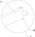
Fig. 5 is an enlarged schematic perspective view of part a of the present invention.
Fig. 6 is a perspective view of a dispersing assembly according to the present invention from a first perspective.
Fig. 7 is a perspective view of a dispersing assembly according to a second aspect of the present invention.
Fig. 8 is a schematic perspective view of a cooling assembly of the present invention.
Figure 9 is a perspective view of the dehumidifying module of the present invention.
Fig. 10 is a first perspective view of the vibration assembly of the present invention.
Fig. 11 is a second perspective view of the vibration assembly of the present invention.
Fig. 12 is a perspective view of the hydraulic spring according to the present invention.
The meaning of the reference symbols in the figures: 1: mounting bracket, 2: first cylinder, 21: discharge curved tube, 22: first conveying screw, 23: toggle plate, 24: square notch, 25: through hole, 3: feeding pipe, 4: first motor module, 41: speed reducer, 5: temperature-controlled blower module, 6: first pipe, 7: accommodating tray, 71: second duct, 8: dispersion assembly, 81: second cylinder, 82: second motor module, 83: batch hopper, 84: second conveying screw, 9: cooling assembly, 91: temperature controlled chiller module, 92: third pipe, 93: first trapezoidal connection pipe, 10: dehumidifying component, 101: dehumidifier module, 102: fourth pipe, 103: second trapezoidal connecting pipe, 11: vibration assembly, 111: installation box body, 112: vibration motor, 12: a hydraulic spring.
Detailed Description
Reference herein to an embodiment means that a particular feature, structure, or characteristic described in connection with the embodiment can be included in at least one embodiment of the invention. The appearances of the phrase in various places in the specification are not necessarily all referring to the same embodiment, nor are separate or alternative embodiments mutually exclusive of other embodiments. It is explicitly and implicitly understood by one skilled in the art that the embodiments described herein can be combined with other embodiments.
Example 1
An anti-accumulation microbial fertilizer dryer is shown in figures 1-5 and comprises a mounting frame 1, a first cylinder 2, a discharge bent pipe 21, a first spiral conveying plate 22, a poking plate 23, a feeding pipe 3, a first motor module 4, a speed reducer 41, a temperature control blower module 5, a first pipeline 6, a containing disc 7 and a second pipeline 71, wherein the first cylinder 2 is connected with the mounting frame 1 in a sliding manner, the discharge bent pipe 21 is fixed on the left side of the first cylinder 2 through a bolt, the first spiral conveying plate 22 is rotatably connected with the first cylinder 2 through a bearing, a square notch 24 is formed in the first spiral conveying plate 22, the poking plate 23 is hinged in the square notch 24, the poking plate 23 is irregularly distributed on the spiral plate of the first spiral conveying plate 22, a through hole 25 is formed in the first spiral conveying plate 22 in a penetrating manner, a fixed connection pipe 3 is arranged at the top of the first cylinder 2, the feeding pipe 3 is communicated with the first cylinder 2, a biological fertilizer enters the first cylinder 2 through the feeding pipe 3, the first motor module 4 and the speed reducer 41 are installed on the right side of the first cylinder 2, the first motor module 41 is connected with the speed reducer through an input shaft, the output state of the motor of the first motor module 4 can be converted into a low-speed high-torque mode, the output shaft of the speed reducer 41 is connected with the central shaft of the first spiral conveying plate 22, the temperature control blower module 5 is installed at the bottom of the mounting frame 1, the air outlet of the temperature control blower module 5 is communicated with the first pipeline 6, the top of the first pipeline 6 is communicated with the accommodating disc 7 through bolts, six second pipelines 71 are uniformly distributed and fixedly connected to the side surface of the accommodating disc 7 along the circumferential direction, the six second pipelines 71 are communicated with the right side wall of the first cylinder 2, and air is injected into the first cylinder 2 through the second pipelines 71; the amplitude of the swing generated by the articulation of the toggle plate 23 within the square notch 24 is less than 160 degrees.
As shown in fig. 1, 6 and 7, the mounting rack further comprises a dispersion assembly 8, wherein the dispersion assembly 8 is arranged on the top of the mounting rack 1; the dispersing component 8 comprises a second cylinder 81, a second motor module 82, a feeding hopper 83 and a second spiral conveying plate 84, the top of the mounting frame 1 is fixedly connected with the second cylinder 81 through a bolt, the feeding hopper 83 is bolted to the top of the second cylinder 81, a discharge port at the left side of the second cylinder 81 is connected with the feeding pipe 3 in a sliding mode, the second motor module 82 is arranged at the right side of the second cylinder 81, the second spiral conveying plate 84 is connected with the second cylinder 81 in a rotating mode through a bearing, and a central shaft of the second spiral conveying plate 84 is connected with a motor output shaft of the second motor module 82 through a coupling.
As shown in fig. 1 and 8, the cooling device further comprises a cooling assembly 9, wherein the cooling assembly 9 is arranged on one side of the mounting frame 1; the cooling assembly 9 comprises a temperature control refrigerator module 91, a third pipeline 92 and a first trapezoidal connecting pipe 93, the temperature control refrigerator module 91 is installed on the right portion of the rear side of the mounting frame 1, the refrigeration output end of the temperature control refrigerator module 91 is communicated with the third pipeline 92, cold air produced by the temperature control refrigerator module 91 is conveyed through the third pipeline 92, a heat insulation layer is sleeved on the outer layer of the third pipeline 92, the top of the third pipeline 92 is communicated with the first trapezoidal connecting pipe 93 through bolt fixing, and the first trapezoidal connecting pipe 93 is communicated with the second barrel 81.
As shown in fig. 1 and 9, the dehumidifier further comprises a dehumidifying component 10, and one side of the mounting rack 1 is provided with the dehumidifying component 10; dehumidifier module 101 is drawn together to dehumidification subassembly 10, fourth pipeline 102 and the trapezoidal connecting pipe of second 103, dehumidifier module 101 is installed to the rear side left part of mounting bracket 1, the moisture in the fixed region air of dehumidifier module 101 during operation extraction, the inlet scoop of dehumidifier module 101 communicates fourth pipeline 102, the trapezoidal connecting pipe of fourth pipeline 102 top fixed intercommunication second 103, the inside humid air of the first barrel of second 103 and the first barrel 2 intercommunication extraction, avoid moisture to deposit in first barrel 2.
The fermented biological fertilizer is fed in from a feeding hopper 83 in a controlled amount, the biological fertilizer enters the second cylinder 81, the volume of the biological fertilizer in the second cylinder 81 is kept to be one third of the volume of the second cylinder 81 all the time, the rotating speed of a second motor module 82 is adjusted to 35rmp, the temperature of a temperature control refrigerator module 91 is adjusted to 25 ℃, cold air enters the second cylinder 81 through a third pipeline 92, the fed biological fertilizer is dispersed by utilizing spiral space in the rotating process of a second spiral conveying plate 84, the biological fertilizer is prevented from being extruded to form accumulation in a large amount, the temperature of the biological fertilizer is reduced after the cold air enters the second cylinder 81, the temperature of the biological fertilizer is reduced, the biological bacteria in the biological fertilizer are prevented from being killed by accumulated heat in the subsequent biological fertilizer heating and drying process, the biological fertilizer falls into a feeding pipe 3 through a discharge port of the second cylinder 81 and enters a first cylinder 2 by the accumulated heat, the air outlet temperature of a temperature control blower module 5 is controlled to be 48 ℃, the motor of the first motor module 4 forms a power output mode with low rotating speed and high torque through the speed reducer 41, the effect of stably rotating the first spiral conveying plate 22 is realized, the rotating speed of the first spiral conveying plate 22 is adjusted to be kept at 25rmp, the temperature control blower module 5 outputs 48 ℃ low-temperature airflow with high wind pressure and low wind pressure through the first pipeline 6 and temporarily stays in the accommodating disc 7, air is supplied to the inside of the first cylinder 2 through the six second pipelines 71, finally low-temperature airflow with high wind volume and low wind pressure is formed to increase the airflow effect, the low-temperature airflow integrally flows inside the first cylinder 2 through the through hole 25 of the first spiral conveying plate 22, the first spiral conveying plate 22 rotates to push the bio-fertilizer to move towards the discharging curved pipe 21, the shifting plate 23 swings downwards and contacts the agglomerated bio-fertilizer when rotating to be close to the lower part of the first cylinder 2 along with the first spiral conveying plate 22, pushing away the partial pushing away that agglomerates when promoting bio-fertilizer, the contained angle that driver plate 23 and first auger delivery board 22 formed is at 40, can make driver plate 23 still can contact with bio-fertilizer swinging to the extreme position like this, driver plate 23 follows the rotatory in-process of a week of first auger delivery board 22, can use the pin joint as the center pin and swing from top to bottom in square notch 24, the bio-fertilizer that will adsorb on driver plate 23 shakes off, avoid driver plate 23 and bio-fertilizer to appear the adhesion, and the bio-fertilizer that is broken up dries under the low temperature air current, and the material distribution of raising under the stirring of driver plate 23 is more dispersed, thereby reduce bio-fertilizer bonding phenomenon, avoid and reduce the chance that the interior bacterial of bio-fertilizer dies because of not being able to bear the temperature, ensure bio-fertilizer quality, the aqueous vapor of low temperature evaporation floats and accompanies the work of dehumidifier module 101, get into fourth pipeline 102 through second trapezoidal connecting pipe 103 at the top of first barrel 2, be handled by dehumidifier module 101, finally make the bio-fertilizer after drying reduce to 26%, do not have the moisture content, the caking of the low temperature fertilizer has ensured the quality of bio-fertilizer.
Example 2
On the basis of the embodiment 1, as shown in fig. 1 and 10, the vibration device further comprises a vibration component 11, wherein the vibration component 11 is arranged at the bottom of the first cylinder 2; the vibration assembly 11 comprises an installation box body 111 and a vibration motor 112, the installation box body 111 is welded at the bottom of the first cylinder body 2, and the vibration motor 112 is fixed in the installation box body 111 through bolts; if the first cylinder 2 slides up and down in the longitudinal direction, the vibration motor 112 is fixed in the mounting box 111 at the mounting angle of the first cylinder 2, and the first cylinder 2 vibrates up and down due to the excitation force generated after the vibration motor 112 works; if the first cylinder 2 slides horizontally, the vibration motor 112 is fixed in the mounting box 111 at a mounting angle perpendicular to the first cylinder 2, and the first cylinder 2 vibrates horizontally due to the exciting force generated after the vibration motor 112 operates, in this embodiment, the first cylinder 2 is mounted in a manner of sliding vertically.
As shown in fig. 1, 11, 12, still include hydraulic spring 12, the one end of first barrel 2 bottom symmetry swing joint hydraulic spring 12, hydraulic spring 12's the other end and mounting bracket 1 swing joint, hydraulic spring 12 provides stable vibration range when first barrel 2 vibrates, avoids damaging mounting bracket 1, increase of service life.
Bio-fertilizer is in the drying process, and vibrating motor 112 work makes first barrel 2 appear vibrating from top to bottom, and then vibrates the inside bio-fertilizer of first barrel 2, and the bio-fertilizer is abundant to mix with the low temperature air current in the vibration, can dry fast, improvement drying efficiency by a wide margin.
The above description is only an embodiment of the present invention, and not intended to limit the scope of the present invention, and all modifications of equivalent structures and equivalent processes, which are made by the present specification, or directly or indirectly applied to other related technical fields, are included in the scope of the present invention.
Claims (6)
1. The utility model provides an anti-accumulation microbial fertilizer desiccator, is including mounting bracket (1), first barrel (2), row's material bent pipe (21), first auger delivery board (22), first barrel (2) of sliding connection on mounting bracket (1), first barrel (2) one side-mounting row's material bent pipe (21), first auger delivery board (22), characterized by are connected to first barrel (2) internal rotation formula: the automatic temperature control device is characterized by further comprising a poking plate (23), a feeding pipe (3), a first motor module (4), a speed reducer (41), a temperature control blower module (5), a first pipeline (6), a containing disc (7) and a second pipeline (71), wherein a square notch (24) is formed in the first spiral conveying plate (22), the poking plate (23) is movably connected in the square notch (24), a through hole (25) is formed in the first spiral conveying plate (22) in a penetrating mode, the feeding pipe (3) is arranged on the upper portion of the first cylinder (2), the feeding pipe (3) is communicated with the first cylinder (2), the first motor module (4) and the speed reducer (41) are arranged on one side, opposite to the discharging curved pipe (21), of the first cylinder (2), a motor output shaft of the first motor module (4) is connected with an input shaft of the speed reducer (41) through a shaft coupling, the output state of the first motor module (4) is converted into a low-speed high-torque mode, the output shaft of the speed motor module (41) is connected with a central shaft of the first spiral conveying plate (22), the temperature control blower module (5) is fixedly connected with the side face of the containing disc (7), the first pipeline (7) and the second pipeline (71) is fixedly connected with the side face of the containing disc (7), the second pipelines (71) are communicated with the side surface of the first cylinder (2), and the installation positions of the second pipelines (71) and the first motor module (4) are positioned at the same side;
the device also comprises a dispersing component (8), wherein the dispersing component (8) is arranged at the top of the mounting rack (1); the dispersing component (8) comprises a second cylinder (81), a second motor module (82), a feeding hopper (83) and a second spiral conveying plate (84), the top of the mounting frame (1) is fixedly connected with the second cylinder (81), the feeding hopper (83) is arranged at the top of the second cylinder (81), the discharge port of the second cylinder (81) is connected with the feeding pipe (3) in a sliding manner, the second motor module (82) is arranged on one side of the second cylinder (81) opposite to the discharge port, the second spiral conveying plate (84) is connected in the second cylinder (81) in a rotating manner, and the central shaft of the second spiral conveying plate (84) is connected with the motor output shaft of the second motor module (82) through a coupler;
the cooling device is characterized by also comprising a cooling component (9), wherein the cooling component (9) is arranged on one side of the mounting rack (1); the cooling assembly (9) comprises a temperature control refrigerator module (91), a third pipeline (92) and a first trapezoidal connecting pipe (93), the temperature control refrigerator module (91) is arranged on one side of the mounting rack (1), the refrigeration output end of the temperature control refrigerator module (91) is fixedly connected with the third pipeline (92), the top of the third pipeline (92) is fixedly connected with the first trapezoidal connecting pipe (93), and the first trapezoidal connecting pipe (93) is communicated with the second barrel (81).
2. The anti-piling microbial fertilizer dryer as claimed in claim 1, wherein: the swing amplitude generated by the movable connection of the poking plate (23) in the square notch (24) is less than 160 degrees.
3. The drier of claim 1, wherein: the dehumidifying device is characterized by further comprising a dehumidifying component (10), wherein the dehumidifying component (10) is arranged on one side of the mounting rack (1); dehumidifying component (10) sets up dehumidifier module (101) including dehumidifier module (101), fourth pipeline (102) and trapezoidal connecting pipe of second (103) one side of mounting bracket (1), inlet scoop rigid coupling fourth pipeline (102) of dehumidifier module (101), fourth pipeline (102) top rigid coupling trapezoidal connecting pipe of second (103), and trapezoidal connecting pipe of second (103) and first barrel (2) switch-on.
4. The drier of claim 1, wherein: the vibration device also comprises a vibration component (11), wherein the vibration component (11) is arranged at the bottom of the first cylinder (2); the vibration assembly (11) comprises an installation box body (111) and a vibration motor (112), the bottom of the first cylinder body (2) is fixedly connected with the installation box body (111), and the vibration motor (112) is fixedly connected in the installation box body (111).
5. The anti-piling microbial fertilizer dryer as claimed in claim 4, wherein: the vibration motor (112) takes the first cylinder (2) as a reference object, and is fixedly connected in the mounting box body (111) at two optional angles of parallel mounting and vertical mounting, and the first cylinder (2) presents two excitation directions opposite to the mounting angle.
6. The drier of claim 4, wherein: the hydraulic cylinder is characterized by further comprising a hydraulic spring (12), the bottom of the first cylinder body (2) is symmetrically and movably connected with one end of the hydraulic spring (12), and the other end of the hydraulic spring (12) is movably connected with the mounting frame (1).
Priority Applications (1)
| Application Number | Priority Date | Filing Date | Title |
|---|---|---|---|
| CN202211478957.8A CN115523740B (en) | 2022-11-24 | 2022-11-24 | Anti-accumulation microbial fertilizer dryer |
Applications Claiming Priority (1)
| Application Number | Priority Date | Filing Date | Title |
|---|---|---|---|
| CN202211478957.8A CN115523740B (en) | 2022-11-24 | 2022-11-24 | Anti-accumulation microbial fertilizer dryer |
Publications (2)
| Publication Number | Publication Date |
|---|---|
| CN115523740A CN115523740A (en) | 2022-12-27 |
| CN115523740B true CN115523740B (en) | 2023-02-28 |
Family
ID=84705160
Family Applications (1)
| Application Number | Title | Priority Date | Filing Date |
|---|---|---|---|
| CN202211478957.8A Active CN115523740B (en) | 2022-11-24 | 2022-11-24 | Anti-accumulation microbial fertilizer dryer |
Country Status (1)
| Country | Link |
|---|---|
| CN (1) | CN115523740B (en) |
Families Citing this family (1)
| Publication number | Priority date | Publication date | Assignee | Title |
|---|---|---|---|---|
| CN117283751B (en) * | 2023-11-27 | 2024-02-06 | 常州市星干干燥设备有限公司 | Fluororesin spin flash evaporation drying conveying equipment for ETFE powder drying |
Citations (10)
| Publication number | Priority date | Publication date | Assignee | Title |
|---|---|---|---|---|
| CN204227858U (en) * | 2014-10-16 | 2015-03-25 | 夏勇 | A kind of fertilizer dryer |
| CN206695547U (en) * | 2017-05-06 | 2017-12-01 | 平罗县德凌化工科技有限公司 | A kind of organic fertilizer drying plant |
| CN207231131U (en) * | 2017-09-30 | 2018-04-13 | 广东天高科技有限公司 | Glass putty drying machine |
| CN208859996U (en) * | 2018-05-31 | 2019-05-14 | 江苏省恒康肥业有限公司 | A kind of chemical fertilizer drying equipment |
| KR102040188B1 (en) * | 2019-09-03 | 2019-11-04 | 하태준 | Method for manufacturing soil reforming fertilizer of natural component |
| CN112197536A (en) * | 2019-06-23 | 2021-01-08 | 江苏汉菱肥业有限责任公司 | Drying equipment is used in amino acid fertilizer production |
| CN213514977U (en) * | 2020-11-10 | 2021-06-22 | 重庆市艳鑫有机肥料有限公司 | Plant enzymolysis's organic fertilizer production facility |
| CN114349579A (en) * | 2022-01-19 | 2022-04-15 | 广东宝禾富硒肥业发展有限公司 | Production process of selenium-rich amino acid organic fertilizer |
| CN115435562A (en) * | 2022-10-11 | 2022-12-06 | 菅勃勃 | Drying, cooling and conveying equipment for organic fertilizer production and use method |
| CN218096996U (en) * | 2022-09-02 | 2022-12-20 | 黄咪 | Excrement drying device for livestock breeding |
-
2022
- 2022-11-24 CN CN202211478957.8A patent/CN115523740B/en active Active
Patent Citations (10)
| Publication number | Priority date | Publication date | Assignee | Title |
|---|---|---|---|---|
| CN204227858U (en) * | 2014-10-16 | 2015-03-25 | 夏勇 | A kind of fertilizer dryer |
| CN206695547U (en) * | 2017-05-06 | 2017-12-01 | 平罗县德凌化工科技有限公司 | A kind of organic fertilizer drying plant |
| CN207231131U (en) * | 2017-09-30 | 2018-04-13 | 广东天高科技有限公司 | Glass putty drying machine |
| CN208859996U (en) * | 2018-05-31 | 2019-05-14 | 江苏省恒康肥业有限公司 | A kind of chemical fertilizer drying equipment |
| CN112197536A (en) * | 2019-06-23 | 2021-01-08 | 江苏汉菱肥业有限责任公司 | Drying equipment is used in amino acid fertilizer production |
| KR102040188B1 (en) * | 2019-09-03 | 2019-11-04 | 하태준 | Method for manufacturing soil reforming fertilizer of natural component |
| CN213514977U (en) * | 2020-11-10 | 2021-06-22 | 重庆市艳鑫有机肥料有限公司 | Plant enzymolysis's organic fertilizer production facility |
| CN114349579A (en) * | 2022-01-19 | 2022-04-15 | 广东宝禾富硒肥业发展有限公司 | Production process of selenium-rich amino acid organic fertilizer |
| CN218096996U (en) * | 2022-09-02 | 2022-12-20 | 黄咪 | Excrement drying device for livestock breeding |
| CN115435562A (en) * | 2022-10-11 | 2022-12-06 | 菅勃勃 | Drying, cooling and conveying equipment for organic fertilizer production and use method |
Also Published As
| Publication number | Publication date |
|---|---|
| CN115523740A (en) | 2022-12-27 |
Similar Documents
| Publication | Publication Date | Title |
|---|---|---|
| CN115523740B (en) | Anti-accumulation microbial fertilizer dryer | |
| CN204841583U (en) | Static compost extruder grain apparatus for producing of biological straw of granule | |
| CN110002715A (en) | A kind of two-stage sludge drying equipment system | |
| CN201919595U (en) | Grain dryer | |
| CN213433985U (en) | Mixing arrangement is used in water-soluble fertile production | |
| CN207688597U (en) | A kind of biomass fertilizers drying unit | |
| CN114854531A (en) | Fermented feed batch production device | |
| CN207276507U (en) | A kind of NEW TYPE OF COMPOSITE bacterial manure production line | |
| CN208238461U (en) | Circulation drying device is used in a kind of production of desiccant | |
| CN216953881U (en) | Organic fertilizer drying device | |
| CN106431544A (en) | Closed anti-blockage double-shaft pile turning type intelligent aerobic composting device | |
| CN213179155U (en) | Drying equipment for granular organic fertilizer | |
| CN2427271Y (en) | High efficiency, energy-saving pelletizing and drying tower | |
| CN209181436U (en) | A kind of Chinese rose nursery organic fertilizer dryer | |
| CN207515365U (en) | A kind of pesticide granules production drying unit suitable for suspending agent class pesticide | |
| CN201509580U (en) | Cooler used in low-temperature environment | |
| CN214501974U (en) | Biological feed drying device | |
| CN220852904U (en) | Drying device is used in maize seed processing | |
| CN2541801Y (en) | High humidifying viscous material fast drying machine | |
| CN214483192U (en) | Biological feed processing system | |
| CN113251782B (en) | High-efficient desiccator of intelligence chemical fertilizer | |
| CN221077040U (en) | Fertilizer quick drying device | |
| CN220703591U (en) | Biomass pellet fuel processing device | |
| CN219103611U (en) | Tower type drying device | |
| CN215559971U (en) | Horizontal single-shaft heating, air-entrapping and fermenting stirrer |
Legal Events
| Date | Code | Title | Description |
|---|---|---|---|
| PB01 | Publication | ||
| PB01 | Publication | ||
| SE01 | Entry into force of request for substantive examination | ||
| SE01 | Entry into force of request for substantive examination | ||
| GR01 | Patent grant | ||
| GR01 | Patent grant |