CN115340145A - Irradiation device and method - Google Patents
Irradiation device and method Download PDFInfo
- Publication number
- CN115340145A CN115340145A CN202211020272.9A CN202211020272A CN115340145A CN 115340145 A CN115340145 A CN 115340145A CN 202211020272 A CN202211020272 A CN 202211020272A CN 115340145 A CN115340145 A CN 115340145A
- Authority
- CN
- China
- Prior art keywords
- chamber
- radiation sources
- irradiation
- fluid
- irradiation device
- Prior art date
- Legal status (The legal status is an assumption and is not a legal conclusion. Google has not performed a legal analysis and makes no representation as to the accuracy of the status listed.)
- Withdrawn
Links
- 238000000034 method Methods 0.000 title claims abstract description 28
- 239000012530 fluid Substances 0.000 claims abstract description 178
- 230000005855 radiation Effects 0.000 claims abstract description 173
- 238000001816 cooling Methods 0.000 claims abstract description 117
- 239000000463 material Substances 0.000 claims abstract description 85
- 230000007246 mechanism Effects 0.000 claims abstract description 30
- 230000001678 irradiating effect Effects 0.000 claims abstract description 5
- 238000012546 transfer Methods 0.000 claims description 41
- 239000000356 contaminant Substances 0.000 claims description 8
- XLYOFNOQVPJJNP-UHFFFAOYSA-N water Substances O XLYOFNOQVPJJNP-UHFFFAOYSA-N 0.000 claims description 8
- 239000002274 desiccant Substances 0.000 claims description 5
- 230000015572 biosynthetic process Effects 0.000 claims description 4
- 239000007788 liquid Substances 0.000 claims description 3
- 238000000576 coating method Methods 0.000 claims description 2
- 238000013500 data storage Methods 0.000 claims description 2
- 238000001514 detection method Methods 0.000 claims description 2
- 239000000565 sealant Substances 0.000 claims description 2
- 239000011248 coating agent Substances 0.000 claims 1
- 230000017525 heat dissipation Effects 0.000 claims 1
- 238000004891 communication Methods 0.000 abstract description 12
- 238000004659 sterilization and disinfection Methods 0.000 description 19
- 230000004907 flux Effects 0.000 description 14
- 229910052751 metal Inorganic materials 0.000 description 14
- 239000002184 metal Substances 0.000 description 14
- 239000004065 semiconductor Substances 0.000 description 14
- 230000003287 optical effect Effects 0.000 description 12
- 239000010453 quartz Substances 0.000 description 9
- VYPSYNLAJGMNEJ-UHFFFAOYSA-N silicon dioxide Inorganic materials O=[Si]=O VYPSYNLAJGMNEJ-UHFFFAOYSA-N 0.000 description 9
- 230000001954 sterilising effect Effects 0.000 description 8
- 238000009303 advanced oxidation process reaction Methods 0.000 description 6
- 239000011159 matrix material Substances 0.000 description 6
- QSHDDOUJBYECFT-UHFFFAOYSA-N mercury Chemical compound [Hg] QSHDDOUJBYECFT-UHFFFAOYSA-N 0.000 description 6
- 230000037361 pathway Effects 0.000 description 6
- 239000000758 substrate Substances 0.000 description 6
- 230000005540 biological transmission Effects 0.000 description 5
- 239000004020 conductor Substances 0.000 description 5
- 239000003989 dielectric material Substances 0.000 description 5
- 239000007789 gas Substances 0.000 description 5
- 238000004382 potting Methods 0.000 description 5
- 230000032770 biofilm formation Effects 0.000 description 4
- 238000013461 design Methods 0.000 description 4
- -1 dielectric Substances 0.000 description 4
- 230000000813 microbial effect Effects 0.000 description 4
- 239000002245 particle Substances 0.000 description 4
- 239000007787 solid Substances 0.000 description 4
- 238000011109 contamination Methods 0.000 description 3
- 239000013078 crystal Substances 0.000 description 3
- 230000000694 effects Effects 0.000 description 3
- 230000008569 process Effects 0.000 description 3
- 238000001228 spectrum Methods 0.000 description 3
- 238000009281 ultraviolet germicidal irradiation Methods 0.000 description 3
- IJGRMHOSHXDMSA-UHFFFAOYSA-N Atomic nitrogen Chemical compound N#N IJGRMHOSHXDMSA-UHFFFAOYSA-N 0.000 description 2
- MHAJPDPJQMAIIY-UHFFFAOYSA-N Hydrogen peroxide Chemical compound OO MHAJPDPJQMAIIY-UHFFFAOYSA-N 0.000 description 2
- OAICVXFJPJFONN-UHFFFAOYSA-N Phosphorus Chemical compound [P] OAICVXFJPJFONN-UHFFFAOYSA-N 0.000 description 2
- GWEVSGVZZGPLCZ-UHFFFAOYSA-N Titan oxide Chemical compound O=[Ti]=O GWEVSGVZZGPLCZ-UHFFFAOYSA-N 0.000 description 2
- 238000010521 absorption reaction Methods 0.000 description 2
- 150000001875 compounds Chemical class 0.000 description 2
- 230000008878 coupling Effects 0.000 description 2
- 238000010168 coupling process Methods 0.000 description 2
- 238000005859 coupling reaction Methods 0.000 description 2
- 230000000249 desinfective effect Effects 0.000 description 2
- 238000010438 heat treatment Methods 0.000 description 2
- 230000005764 inhibitory process Effects 0.000 description 2
- 238000002347 injection Methods 0.000 description 2
- 239000007924 injection Substances 0.000 description 2
- 239000012569 microbial contaminant Substances 0.000 description 2
- 238000005192 partition Methods 0.000 description 2
- 229920000642 polymer Polymers 0.000 description 2
- 239000000523 sample Substances 0.000 description 2
- 238000002834 transmittance Methods 0.000 description 2
- YJLIKUSWRSEPSM-WGQQHEPDSA-N (2r,3r,4s,5r)-2-[6-amino-8-[(4-phenylphenyl)methylamino]purin-9-yl]-5-(hydroxymethyl)oxolane-3,4-diol Chemical compound C=1C=C(C=2C=CC=CC=2)C=CC=1CNC1=NC=2C(N)=NC=NC=2N1[C@@H]1O[C@H](CO)[C@@H](O)[C@H]1O YJLIKUSWRSEPSM-WGQQHEPDSA-N 0.000 description 1
- 229910000497 Amalgam Inorganic materials 0.000 description 1
- 241000894006 Bacteria Species 0.000 description 1
- YZCKVEUIGOORGS-OUBTZVSYSA-N Deuterium Chemical compound [2H] YZCKVEUIGOORGS-OUBTZVSYSA-N 0.000 description 1
- 239000004593 Epoxy Substances 0.000 description 1
- QIVBCDIJIAJPQS-VIFPVBQESA-N L-tryptophane Chemical compound C1=CC=C2C(C[C@H](N)C(O)=O)=CNC2=C1 QIVBCDIJIAJPQS-VIFPVBQESA-N 0.000 description 1
- 229910006404 SnO 2 Inorganic materials 0.000 description 1
- QIVBCDIJIAJPQS-UHFFFAOYSA-N Tryptophan Natural products C1=CC=C2C(CC(N)C(O)=O)=CNC2=C1 QIVBCDIJIAJPQS-UHFFFAOYSA-N 0.000 description 1
- 241000700605 Viruses Species 0.000 description 1
- 239000006096 absorbing agent Substances 0.000 description 1
- 230000009471 action Effects 0.000 description 1
- QVGXLLKOCUKJST-UHFFFAOYSA-N atomic oxygen Chemical compound [O] QVGXLLKOCUKJST-UHFFFAOYSA-N 0.000 description 1
- 230000003385 bacteriostatic effect Effects 0.000 description 1
- 230000008901 benefit Effects 0.000 description 1
- 230000003115 biocidal effect Effects 0.000 description 1
- 239000003139 biocide Substances 0.000 description 1
- 230000033228 biological regulation Effects 0.000 description 1
- 238000006243 chemical reaction Methods 0.000 description 1
- 229910052805 deuterium Inorganic materials 0.000 description 1
- 239000010432 diamond Substances 0.000 description 1
- 229910003460 diamond Inorganic materials 0.000 description 1
- 238000010891 electric arc Methods 0.000 description 1
- 239000008393 encapsulating agent Substances 0.000 description 1
- 238000005516 engineering process Methods 0.000 description 1
- 230000005284 excitation Effects 0.000 description 1
- 230000005669 field effect Effects 0.000 description 1
- 238000002189 fluorescence spectrum Methods 0.000 description 1
- 230000006870 function Effects 0.000 description 1
- 230000036541 health Effects 0.000 description 1
- 230000000415 inactivating effect Effects 0.000 description 1
- 239000011261 inert gas Substances 0.000 description 1
- 239000003112 inhibitor Substances 0.000 description 1
- 229910010272 inorganic material Inorganic materials 0.000 description 1
- 239000011147 inorganic material Substances 0.000 description 1
- 230000001788 irregular Effects 0.000 description 1
- 238000007726 management method Methods 0.000 description 1
- 229910052753 mercury Inorganic materials 0.000 description 1
- 244000005700 microbiome Species 0.000 description 1
- 239000000203 mixture Substances 0.000 description 1
- 238000012544 monitoring process Methods 0.000 description 1
- 239000002105 nanoparticle Substances 0.000 description 1
- 229930027945 nicotinamide-adenine dinucleotide Natural products 0.000 description 1
- BOPGDPNILDQYTO-NNYOXOHSSA-N nicotinamide-adenine dinucleotide Chemical compound C1=CCC(C(=O)N)=CN1[C@H]1[C@H](O)[C@H](O)[C@@H](COP(O)(=O)OP(O)(=O)OC[C@@H]2[C@H]([C@@H](O)[C@@H](O2)N2C3=NC=NC(N)=C3N=C2)O)O1 BOPGDPNILDQYTO-NNYOXOHSSA-N 0.000 description 1
- 229910052757 nitrogen Inorganic materials 0.000 description 1
- 150000007523 nucleic acids Chemical class 0.000 description 1
- 102000039446 nucleic acids Human genes 0.000 description 1
- 108020004707 nucleic acids Proteins 0.000 description 1
- 239000011368 organic material Substances 0.000 description 1
- 230000003647 oxidation Effects 0.000 description 1
- 238000007254 oxidation reaction Methods 0.000 description 1
- 239000001301 oxygen Substances 0.000 description 1
- 229910052760 oxygen Inorganic materials 0.000 description 1
- 244000052769 pathogen Species 0.000 description 1
- 230000000737 periodic effect Effects 0.000 description 1
- 230000001699 photocatalysis Effects 0.000 description 1
- 229920001296 polysiloxane Polymers 0.000 description 1
- 230000006798 recombination Effects 0.000 description 1
- 238000005215 recombination Methods 0.000 description 1
- 230000009467 reduction Effects 0.000 description 1
- 238000002310 reflectometry Methods 0.000 description 1
- 229910052594 sapphire Inorganic materials 0.000 description 1
- 239000010980 sapphire Substances 0.000 description 1
- 229920005573 silicon-containing polymer Polymers 0.000 description 1
- 230000003068 static effect Effects 0.000 description 1
- 238000012360 testing method Methods 0.000 description 1
- 230000001052 transient effect Effects 0.000 description 1
- 238000000411 transmission spectrum Methods 0.000 description 1
- 239000002918 waste heat Substances 0.000 description 1
Images


Classifications
-
- A—HUMAN NECESSITIES
- A61—MEDICAL OR VETERINARY SCIENCE; HYGIENE
- A61L—METHODS OR APPARATUS FOR STERILISING MATERIALS OR OBJECTS IN GENERAL; DISINFECTION, STERILISATION OR DEODORISATION OF AIR; CHEMICAL ASPECTS OF BANDAGES, DRESSINGS, ABSORBENT PADS OR SURGICAL ARTICLES; MATERIALS FOR BANDAGES, DRESSINGS, ABSORBENT PADS OR SURGICAL ARTICLES
- A61L2/00—Methods or apparatus for disinfecting or sterilising materials or objects other than foodstuffs or contact lenses; Accessories therefor
- A61L2/02—Methods or apparatus for disinfecting or sterilising materials or objects other than foodstuffs or contact lenses; Accessories therefor using physical phenomena
- A61L2/08—Radiation
- A61L2/10—Ultra-violet radiation
-
- A—HUMAN NECESSITIES
- A61—MEDICAL OR VETERINARY SCIENCE; HYGIENE
- A61L—METHODS OR APPARATUS FOR STERILISING MATERIALS OR OBJECTS IN GENERAL; DISINFECTION, STERILISATION OR DEODORISATION OF AIR; CHEMICAL ASPECTS OF BANDAGES, DRESSINGS, ABSORBENT PADS OR SURGICAL ARTICLES; MATERIALS FOR BANDAGES, DRESSINGS, ABSORBENT PADS OR SURGICAL ARTICLES
- A61L9/00—Disinfection, sterilisation or deodorisation of air
- A61L9/16—Disinfection, sterilisation or deodorisation of air using physical phenomena
- A61L9/18—Radiation
- A61L9/20—Ultra-violet radiation
-
- C—CHEMISTRY; METALLURGY
- C02—TREATMENT OF WATER, WASTE WATER, SEWAGE, OR SLUDGE
- C02F—TREATMENT OF WATER, WASTE WATER, SEWAGE, OR SLUDGE
- C02F1/00—Treatment of water, waste water, or sewage
- C02F1/30—Treatment of water, waste water, or sewage by irradiation
- C02F1/32—Treatment of water, waste water, or sewage by irradiation with ultraviolet light
- C02F1/325—Irradiation devices or lamp constructions
-
- A—HUMAN NECESSITIES
- A61—MEDICAL OR VETERINARY SCIENCE; HYGIENE
- A61L—METHODS OR APPARATUS FOR STERILISING MATERIALS OR OBJECTS IN GENERAL; DISINFECTION, STERILISATION OR DEODORISATION OF AIR; CHEMICAL ASPECTS OF BANDAGES, DRESSINGS, ABSORBENT PADS OR SURGICAL ARTICLES; MATERIALS FOR BANDAGES, DRESSINGS, ABSORBENT PADS OR SURGICAL ARTICLES
- A61L2202/00—Aspects relating to methods or apparatus for disinfecting or sterilising materials or objects
- A61L2202/10—Apparatus features
- A61L2202/11—Apparatus for generating biocidal substances, e.g. vaporisers, UV lamps
-
- A—HUMAN NECESSITIES
- A61—MEDICAL OR VETERINARY SCIENCE; HYGIENE
- A61L—METHODS OR APPARATUS FOR STERILISING MATERIALS OR OBJECTS IN GENERAL; DISINFECTION, STERILISATION OR DEODORISATION OF AIR; CHEMICAL ASPECTS OF BANDAGES, DRESSINGS, ABSORBENT PADS OR SURGICAL ARTICLES; MATERIALS FOR BANDAGES, DRESSINGS, ABSORBENT PADS OR SURGICAL ARTICLES
- A61L2202/00—Aspects relating to methods or apparatus for disinfecting or sterilising materials or objects
- A61L2202/10—Apparatus features
- A61L2202/12—Apparatus for isolating biocidal substances from the environment
- A61L2202/122—Chambers for sterilisation
-
- A—HUMAN NECESSITIES
- A61—MEDICAL OR VETERINARY SCIENCE; HYGIENE
- A61L—METHODS OR APPARATUS FOR STERILISING MATERIALS OR OBJECTS IN GENERAL; DISINFECTION, STERILISATION OR DEODORISATION OF AIR; CHEMICAL ASPECTS OF BANDAGES, DRESSINGS, ABSORBENT PADS OR SURGICAL ARTICLES; MATERIALS FOR BANDAGES, DRESSINGS, ABSORBENT PADS OR SURGICAL ARTICLES
- A61L2209/00—Aspects relating to disinfection, sterilisation or deodorisation of air
- A61L2209/10—Apparatus features
- A61L2209/11—Apparatus for controlling air treatment
- A61L2209/111—Sensor means, e.g. motion, brightness, scent, contaminant sensors
-
- C—CHEMISTRY; METALLURGY
- C02—TREATMENT OF WATER, WASTE WATER, SEWAGE, OR SLUDGE
- C02F—TREATMENT OF WATER, WASTE WATER, SEWAGE, OR SLUDGE
- C02F2201/00—Apparatus for treatment of water, waste water or sewage
- C02F2201/32—Details relating to UV-irradiation devices
- C02F2201/322—Lamp arrangement
- C02F2201/3222—Units using UV-light emitting diodes [LED]
-
- C—CHEMISTRY; METALLURGY
- C02—TREATMENT OF WATER, WASTE WATER, SEWAGE, OR SLUDGE
- C02F—TREATMENT OF WATER, WASTE WATER, SEWAGE, OR SLUDGE
- C02F2201/00—Apparatus for treatment of water, waste water or sewage
- C02F2201/32—Details relating to UV-irradiation devices
- C02F2201/322—Lamp arrangement
- C02F2201/3227—Units with two or more lamps
-
- C—CHEMISTRY; METALLURGY
- C02—TREATMENT OF WATER, WASTE WATER, SEWAGE, OR SLUDGE
- C02F—TREATMENT OF WATER, WASTE WATER, SEWAGE, OR SLUDGE
- C02F2201/00—Apparatus for treatment of water, waste water or sewage
- C02F2201/32—Details relating to UV-irradiation devices
- C02F2201/322—Lamp arrangement
- C02F2201/3228—Units having reflectors, e.g. coatings, baffles, plates, mirrors
-
- C—CHEMISTRY; METALLURGY
- C02—TREATMENT OF WATER, WASTE WATER, SEWAGE, OR SLUDGE
- C02F—TREATMENT OF WATER, WASTE WATER, SEWAGE, OR SLUDGE
- C02F2201/00—Apparatus for treatment of water, waste water or sewage
- C02F2201/32—Details relating to UV-irradiation devices
- C02F2201/326—Lamp control systems
-
- C—CHEMISTRY; METALLURGY
- C02—TREATMENT OF WATER, WASTE WATER, SEWAGE, OR SLUDGE
- C02F—TREATMENT OF WATER, WASTE WATER, SEWAGE, OR SLUDGE
- C02F2303/00—Specific treatment goals
- C02F2303/04—Disinfection
-
- G—PHYSICS
- G21—NUCLEAR PHYSICS; NUCLEAR ENGINEERING
- G21K—TECHNIQUES FOR HANDLING PARTICLES OR IONISING RADIATION NOT OTHERWISE PROVIDED FOR; IRRADIATION DEVICES; GAMMA RAY OR X-RAY MICROSCOPES
- G21K2201/00—Arrangements for handling radiation or particles
- G21K2201/06—Arrangements for handling radiation or particles using diffractive, refractive or reflecting elements
- G21K2201/065—Arrangements for handling radiation or particles using diffractive, refractive or reflecting elements provided with cooling means
Abstract
An apparatus and method for irradiating a fluid containing a material to be irradiated, comprising: at least one irradiation chamber having at least one inlet and outlet, at least one fluid cooling chamber having at least one inlet and outlet, one or more UV radiation sources coupled to the irradiation chamber, and at least one heat exchange mechanism thermally coupled to the one or more radiation sources and the one or more cooling chambers. At least a portion of the inner surface of the one or more cooling chambers may comprise at least a portion of the outer surface of the one or more irradiation chambers, such that the one or more cooling chambers are in fluid communication with the one or more irradiation chambers.
Description
The application is a divisional application, the original application is PCT application with the application number of PCT/US2018/046184 and the application date of 2018, 08 and 10, and the application number of Chinese country is 201880059065.X and the invention name is 'irradiation device and method', and the application enters the stage of Chinese country at 3 and 11 of 2020.
Technical Field
The present invention generally relates to systems, devices and methods for sterilizing fluids by irradiation. More particularly, the present invention relates to an apparatus, system and method for disinfecting a fluid containing material to be irradiated.
Background
The use of Ultraviolet (UV) radiation to disinfect fluids, including liquids and gases, is well known. The process of inactivating microbial contaminants in fluids using ultraviolet radiation is known as ultraviolet radiation sterilization (UVGI). Ultraviolet radiation has also been used to oxidize organic and inorganic materials in fluids, known as Advanced Oxidation Processes (AOPs), and many commercial AOP systems are in use today. Systems employing UVGI and AOP methods rely on the ability to transmit UV radiation into the fluid in a predictable manner. Having the unit J/cm 2 Can be simply expressed as the dose in W/cm 2 Is the product of UV irradiance in units and exposure time in seconds.
Both AOP and UVGI require a UV source (ultraviolet source). For practical purposes, the output irradiance of the UV source should be maintained and decayed in a predictable manner throughout the useful life of the UV source. This enables the prediction of the replacement cycle of the UV source and the overall performance of the system. UV disinfection systems are often specified to have a certain level of performance using a variety of factors including Reduced Equivalent Dose (RED), end of life (eol) of the lamp, ultraviolet transmittance (UVT) of the fluid, and fouling (lamp window and reactor).
Some NSF and EPA regulations require testing of ultraviolet disinfection systems and that the UV source should operate at the expected EOLL optical output power. In order to comply with the performance specifications of the UV disinfection system over a predicted period of time, the UV source should decay in a predictable manner. Longer EOLLs are also of commercial interest, resulting in longer system life and/or UV source replacement intervals.
There are many types of UV sources. Historically, low pressure mercury vapor lamps, medium pressure mercury vapor lamps, and amalgam lamps have been used as UV sources for disinfection applications. Other UV sources include deuterium lamps, light Emitting Diodes (LEDs), lasers, microplasma sources, and solid state field effect phosphor devices. The micro plasma lamps work on the same principle as large gas discharge lamps but have planar electrodes that produce small localized UV emissions. Solid state sources such as LEDs generate light in a semiconductor material by charge recombination in an active layer where charge injection is applied to the anode and cathode of a semiconductor heterostructure. All of these UV sources have different optimal operating temperatures, wherein UV output flux and/or service life is maximized. Due to the low mercury vapor pressure, most gas discharge lamps are difficult to operate in very cold ambient conditions. In contrast, solid state sources have maximum output at lower ambient temperatures. For example, the output power of a low-pressure mercury lamp may peak at an ambient temperature of 40 degrees celsius, while the optical output power of a 265nm LED is linear with the ambient temperature. The slope of the LED curve may vary depending on the device design, but at lower ambient temperatures the trend remains the same for larger light output powers.
Many LED manufacturers specify a maximum junction temperature that should not be exceeded. The LED junction temperature is the temperature of the active layer sandwiched between the n-type and p-type semiconductor layers of the LED. Exceeding the maximum rated junction temperature may result in a reduction in LED lifetime or other characteristics. In a simplified model, the LEDs can be represented as a series of thermal resistances. For example, the UV LED package may be a Surface Mount Device (SMD) mounted on a circuit board, which itself is mounted on a heat sink or other cooling device. The heat sink may be any heat exchanger or cooling method, such as a passive heat sink, peltier device, active air flow, heat pipe, or the like. The LEDs may be mounted on various electrically and thermally conductive circuit boards, such as Printed Circuit Boards (PCBs), metal Core Printed Circuit Boards (MCPCBs), or Chip On Board (COB). Each connection point from the junction of the LED itself to the ambient environment has a temperature associated with it. These temperatures include the junction temperature of the LEDs, the temperature between LED packages on the circuit board, the temperature between the circuit board and the heat sink, and the ambient temperature. At each connection point, the thermal resistance can be modeled, for example RJS is the thermal resistance of the packaged surface mount LED, RSB is the thermal resistance of the circuit board, and RBA is the thermal resistance of the heat sink or cooling method. The LED junction temperature can be modeled as the sum of each of the thermal resistances times the power lost to heating in the device plus the ambient temperature. This relationship is shown in equation 1.
T J(LED) =T Ambient +∑ i (KR i ×P Heat ) Equation 1
LEDs are unique in most UV sources because heat can be removed by electrically connecting the side of the chip with the side responsible for most of the UV emission. This is in contrast to mercury vapor lamps which have a thermal discharge mainly in the same direction as the light emission through a quartz sleeve which also serves as an arc discharge vessel. LEDs do not require quartz windows because they emit light directly from the active layer of the semiconductor, and the light is transmitted through subsequent layers of the semiconductor to the environment. However, LEDs can be sensitive to electrostatic discharge, moisture, and ambient gases (e.g., oxygen or nitrogen), which can degrade the performance of the LED electrical contacts and semiconductors. Therefore, a quartz window is typically placed over the SMD package of the LED. In UVGI systems, the LED will be protected from the fluid by a window, which if mitigated would make a window on the SMD redundant. If the LEDs are sealed between the circuit board and the window, a single window on the board containing one or more LEDs can be used as the optical window of the liquid disinfection system, enabling the window to be used as part of the pressure vessel of the disinfection system and isolating the LEDs from the fluid. A potting compound such as epoxy or silicone may be used between the plate and the window. The potting may be performed in an environment with low relative humidity and may even be purged with dry air or inert gas to ensure that any voids between the LEDs and the window do not generate undesirable moisture or gas internally. This will also increase the output power of the LED, since it will pass light through one quartz window instead of two. An additional benefit of this type of single window lamp package is that the LED has little effect on heating the window compared to a mercury vapor source that transfers a significant amount of heat to the window. Lower window temperatures are associated with less window fouling. Window fouling can reduce the overall UV transmittance of the window, which in turn reduces the performance of the UVGI and AOP systems. Thus, a robust product design utilizing a UV source will account for the temperature of the UV source during operation by taking heat transfer into account. In this way, the lifetime and output power of the UV source can be better controlled. In addition, it may be possible to improve the output power and lifetime of the UV source using a method of assembling the UV source into the second secondary package.
The UV source is an important component in UVGI systems, but it is only one component in overall system efficiency. The system efficiency can be expressed as the product of the reactor efficiency and the UV source efficiency. In the design of UVGI systems, it is good practice to maximize the exposure time (often referred to as "dwell time") of the fluid to UV radiation, thereby maximizing the dose seen by the fluid. Reactor efficiency is a combination of residence time efficiency and optical efficiency. The optical efficiency of the reactor is a measure of how efficiently the reactor utilizes photons of the UV source to increase the likelihood that a microbial contaminant in the fluid will absorb the photons. One way to increase this possibility is to use a reflective material in the reactor so that photons from the UV source can be reflected if they are not absorbed during their initial passage through the reactor. If there are few absorbers in the fluid and the reflectivity of the material in the reactor is high, the photons can be reflected multiple times in the reactor.
U.S. patent application publications 2012/0318749A1, 2014/0161664A1, and 2014/0240695A1, each incorporated herein by reference, disclose various devices, materials, and methods useful herein for disinfecting fluids by irradiation. However, there remains a need in the art for an improved apparatus and method for irradiation that provides good system efficiency, incorporates adequate thermal management, and can be used with a variety of housings or flow cells while maintaining a compact footprint.
Disclosure of Invention
In one embodiment, the present invention relates to an irradiation device comprising: at least one irradiation chamber for a fluid containing material to be irradiated, the chamber having at least one inlet for flow of fluid into the chamber and at least one outlet for flow of fluid out of the chamber; at least one cooling chamber having at least one inlet for flowing fluid into the chamber and at least one outlet for flowing fluid out of the chamber; one or more UV radiation sources coupled to the at least one irradiation chamber; and at least one heat exchange mechanism thermally coupled with the one or more radiation sources and the at least one cooling chamber; wherein at least a portion of the inner surface of the at least one cooling chamber comprises at least a portion of the outer surface of the at least one irradiation chamber, and the at least one cooling chamber is in fluid communication with the at least one irradiation chamber.
In another embodiment, the invention relates to a method for irradiating a fluid containing a material to be irradiated placed in an irradiation chamber, the irradiation method comprising: (1) providing an irradiation apparatus comprising: at least one irradiation chamber for a fluid containing material to be irradiated, the chamber having at least one inlet for flow of fluid into the chamber and at least one outlet for flow of fluid out of the chamber; at least one cooling chamber having at least one inlet for flowing fluid into the chamber and at least one outlet for flowing fluid out of the chamber; one or more UV radiation sources coupled to the at least one irradiation chamber; and at least one heat exchange mechanism thermally coupled with the one or more radiation sources and the at least one cooling chamber; wherein at least a portion of the inner surface of the at least one cooling chamber comprises at least a portion of the outer surface of the at least one irradiation chamber, and the at least one cooling chamber is in fluid communication with the at least one irradiation chamber, and (2) irradiating the fluid containing the material to be irradiated using the irradiation device.
In another embodiment, the invention relates to an irradiation apparatus and method comprising at least one irradiation chamber for a fluid containing material to be irradiated, said chamber having at least one inlet for flow of fluid into the chamber and at least one outlet for flow of fluid from the chamber; at least one cooling chamber having at least one inlet for flowing fluid into the chamber and at least one outlet for flowing fluid out of the chamber; one or more UV radiation sources coupled to the at least one irradiation chamber; and at least one heat exchange mechanism thermally coupled to the one or more radiation sources and the at least one cooling chamber.
Drawings
The present invention is illustrated and described herein with reference to the various drawings, wherein like reference numerals are used to refer to like elements of the apparatus where appropriate, and wherein:
FIG. 1 is a plan side view showing one exemplary embodiment of an irradiation device of the present invention;
FIG. 2 is a cross-sectional view of the device of FIG. 1 taken along line 2-2;
FIG. 3 is a side plan view showing another apparatus of the present invention;
FIG. 4 is a cross-sectional view of the device of FIG. 3 taken along line 4-4;
FIG. 5 is a plan side view showing a portion of another apparatus of the present invention;
FIG. 6 is a cross-sectional view of the device of FIG. 5 taken along line 6-6;
FIG. 7 is a side plan view showing another device of the present invention;
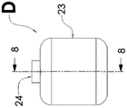
FIG. 8 is a cross-sectional view of the device of FIG. 7 taken along line 8-8;
FIG. 9 is a plan side view showing another device of the present invention;
FIG. 10 is a cross-sectional view of the device of FIG. 9 taken along line 10-10;
FIG. 11 is a side plan view showing another device of the present invention;
FIG. 12 is a cross-sectional view of the device of FIG. 11 taken along line 12-12;
FIG. 13 is a plan side view showing another apparatus of the present invention; and
fig. 14 is a cross-sectional view of the device of fig. 13 taken along line 14-14.
Detailed Description
The present invention provides an improved UV irradiation apparatus, disinfection system and method that utilizes a secondary reactor chamber to cool the UV source and, in one embodiment, also increases the exposure time of the fluid containing the material to be irradiated inside the system. The UV source directly irradiates the primary reactor chamber, whose interior surfaces are typically made of a material that primarily reflects UV and through which UV transmission is minimized. In one embodiment, at least a portion of the inner surface of the secondary reactor comprises at least a portion of the outer surface of the primary reactor chamber. Thus, the secondary reactor chamber receives a portion of the UV radiation transmitted through the material of the primary reactor. In one embodiment, the secondary cooling chamber is in fluid communication with the primary irradiation chamber. Cooling of the UV source is accomplished by at least one heat exchange mechanism thermally coupled to the UV source and the fluid in the secondary cooling chamber.
In another embodiment, the UV irradiation apparatus, sterilization system and method are designed such that a portion of the irradiation from the one or more radiation sources is transmitted from the irradiation chamber into one or more secondary chambers, including but not limited to cooling chambers or outlet conduits, such that the radiation disposed at the surface of the one or more secondary chambers provides a sterilization effect to inhibit the propagation of microbial contamination. The phenomenon of microbial attachment to the surface of an irradiation device, hereinafter referred to as "biofilm" formation, may increase health risks as such contaminants may be transferred to fluids flowing over such surfaces. Biofilm inhibition in disinfection systems is desirable because the process of UV irradiation does not introduce residual biocide to the treated fluid. In areas downstream of the apparatus and system, including but not limited to the "last mile", it is most critical to avoid fouling of the irradiation apparatus and disinfection system later in the process chain than the primary irradiation chamber. In an embodiment, a small portion of the radiation emitted by the UV source may be redirected to the surface of the radiation treatment device and system. Since the fluid contact surface of the reactor is static, the irradiation period for any segment is equal to the total period of the UV source emission. Thus, the irradiance required to achieve biofilm inhibition is much lower than that required for transient irradiation, e.g., fluid passing through a reactor chamber. By requiring low irradiance and relatively low UV power, a small portion of the power emitted by the source can be removed to inhibit biofilm without significantly affecting the fluid disinfection performance of the reactor. Thus, a portion of the irradiation from the one or more radiation sources can be transmitted to the surface of the one or more secondary chambers to inhibit biofilm formation thereon.
In one embodiment of the invention, the device has two three-dimensional chambers, each of which has at least one inlet and at least one outlet for fluid to and from the chamber. The UV radiation source provides radiation to the interior of one of the irradiation chambers. The radiation source has a thermal connection with the other chamber, i.e. the cooling chamber. The thermal connection is between the back and/or front of a heat exchange mechanism connected to a UV source and the fluid in the cooling chamber. The two chambers are in fluid connection, wherein the inlet of one of the chambers is the outlet of the other chamber. The irradiation chamber is typically constructed of a material that primarily reflects UV radiation from the UV source and minimally transmits UV radiation. At least a portion of the chamber interior of the cooling chamber is constituted by the exterior of the irradiation chamber. The UV radiation transmitted through the material of the irradiation chamber thus serves as a UV source for cooling the chamber. This increases the exposure time of the fluid to UV radiation and increases the dose seen by the fluid. In addition, radiation transmitted to the cooling chamber surface inhibits biofilm formation thereon.
The UV radiation source (or sources) may include one or more UV-C radiation sources, or a combination thereof. The UV radiation source (or sources) is typically coupled to a support structure within or on a wall of the irradiation chamber or cooling chamber. The support structure holds UV radiation sources, which may be UV-C radiation sources, such that they selectively direct UV radiation to the interior of an irradiation chamber in which the material to be irradiated is selectively disposed. The peak wavelength can be (dynamically) selected and/or adjusted and multiple wavelengths can be utilized, enabling a spectrum of action for a given organism, thereby improving disinfection efficiency. For example, one or more wavelengths of one or more UV radiation sources may be selected based on the identification of contaminants in the material to be irradiated. The one or more UV radiation sources may deliver one or more wavelengths or combinations of wavelengths to the material to be irradiated. The wavelength may induce fluorescence in the material to be irradiated, thereby allowing for identification of contaminants in the material to be irradiated. Alternatively, the material to be irradiated may be placed in the vicinity of an n-type single crystal semiconductor to be sterilized by generating hydrogen peroxide on the semiconductor surface by band-gap electro-optical excitation. The heat is managed, and optionally recovered, using one or more heat exchange mechanisms, such as thermoelectric cooling devices, vapor chambers, heat sinks, heat dissipating structures, fans, heat transfer materials, materials thermally coupled to fluids, and cooling coatings, disposed substantially adjacent to the UV radiation source. In one embodiment, the heat exchange mechanism is a heat sink or a heat transfer material or a combination thereof. The irradiation device may be moisture protected using a moisture resistant sealant and desiccant coupled to and/or disposed within the support structure. The irradiation assembly can include a monitoring/detection mechanism and control circuitry for dynamically controlling the delivery of UV radiation to the material to be irradiated based on flow rate, water quality, user input, or other operating conditions. Finally, the relevant performance data may be stored in an onboard or external data storage unit.
In various embodiments of the present invention, modular semiconductor UV LED mounting configurations may be provided that include a UV radiation source package containing a single LED or multiple LED "dies" arranged in a matrix or array. The LED die can be selected to provide a plurality of wavelengths in the UV and visible radiation spectrum from about 200nm to about 800 nm. In one exemplary embodiment, the matrix or array includes LED dies that emit at a wavelength in the range of about 200-320nm in order to saturate the absorption mechanism of the nucleocapsid (peak emission centered around 280 nm), and at the same time, peak emission wavelengths spanning about 250-280nm for peak absorption of nucleic acids. In anotherIn an exemplary embodiment, to simulate the optical output spectrum for a low or medium pressure Hg-based UV lamp against a variety of bacteria and viruses, a matrix or array of LED dies utilizes a plurality of wavelengths including at least one wavelength of about 240-260nm, about 260-344nm, about 350-380nm, about 400-450nm, or about 500-600 nm. A further exemplary embodiment is a matrix or array of LED dies emitting in the wavelength range of about 250nm to 300nm in combination with LED dies emitting in the wavelength range of about 350nm to 400nm to achieve photocatalytic oxidation of pathogens or contaminants in water near the crystalline film of an n-type semiconductor such as TiO2, niO or SnO 2. A further exemplary embodiment is a modular mounting configuration comprising a plurality of LED dies emitting wavelengths of about 250-320nm and about 320-400nm arranged in a matrix or array to achieve fluorescence spectra with NADH and tryptophan of particles of biological origin. In another exemplary embodiment, commercially available SETi UV CleanTM LED packages are used. Separate LED dies or a single die bonded to a thermally conductive metal core circuit board (MCPCB) may also be used, such as may be available from The Bergquist Company TM And (4) obtaining the crystal grains.
The LED package may be connected to a heat sink, which in turn is configured to be mounted to a window port of an irradiation chamber. The mounting face of the module may have a gasket or gasket that encloses the LED package with the desiccant to reduce condensed moisture. The heat sink may be circular, square or other suitable shape. Heat from the LEDs is conducted to a heat sink, optionally cooled by forced air, optionally by means of a thermoelectric cooler or other means. The LED package may be electrically connected to a control circuit and a power supply circuit, which are included as part of the replaceable module. Circuitry is included in the replaceable module to provide telemetry and tracking information, such as operating temperature and run time.
A matrix or array of packaged UV LEDs or UV LEDs may be attached to the heat sink. Multiple UV wavelengths can be used to optimize the effect on a particular microorganism. Heat removal from the back side can be assisted by thermoelectric cooling (TEC) and/or vapor chambers. Furthermore, the UV LED package may be top-cooled by conduction through a highly thermally conductive cover layer (e.g., a silicone polymer impregnated with diamond nanoparticles), which may have a single crystal structure.
The surfaces of the heat sink and the metal portion of the UV radiation emitting housing may be flat to mount the LED and the accessory mold or package; or alternatively recessed, to provide a concave reflective structure for the LED and/or to provide a means for attachment. The heat sink may be attached to the irradiation device by a variety of methods including, but not limited to, contact bonding, spring pins, clamps, rotatable clips, screws, by screwing in exemplary embodiments of heat sinks with circular rims having threads cut into them, or by twisting exemplary embodiments of heat sinks with circular rims connected by bayonet connectors.
As previously mentioned, components for the electrical and/or electronic control of the UV radiation source may optionally be included within the sealed unit so that they can act on the UV radiation source while remaining protected from the external environment by such tightness, use of a desiccant or a combination thereof as previously described. In addition, the co-location of these components on the MCPCB, or other means and subsequent thermal bonding with the heat exchange mechanism, may be used to extract heat generated by, for example, the power conversion components. Additionally, these electrical and/or electronic components may include sensors that can determine the operating conditions and status of the UV adjunct sources, including but not limited to photodiodes, thermocouples, thermistors, acoustic sensors, hall probes, galvanic probes, and the like.
The radiation emitter module may be a user replaceable unit, optionally including attached electronics and desiccant material, in order to resist moisture and humidity. The attached electronics can include separate identification and telemetry tracking, as well as an interconnect that is easily disconnected from the large system.
Cooling of the LED package may be aided by a TEC or vapor chamber located between the LED package and the heat sink. The TEC may take the form of a single TEC or multiple modules to provide contact around irregular package geometries (e.g., via designs). Further, an electro-thermal module may be included to collect energy from the waste heat generated.
UV radiation can be transmitted from the LED die through the transmission window, polymer, air, and/or aperture into the irradiation chamber. The transmission window has a transmission spectrum, for example in the UV-C range, which is suitable for the choice of the LED used.
Referring now to fig. 1 and 2, in one exemplary embodiment of the invention, an irradiation device a comprises two three-dimensional chambers 1 and 2, each having an inlet and an outlet for fluid flow into and out of the chamber. The irradiation chamber 1 has an inlet 4 for the flow of fluid into the chamber and an outlet 5 for the flow of fluid out of the chamber. The cooling chamber 2 has an inlet 3 for fluid flow into the chamber and an outlet 4 for fluid flow out of the chamber. The cooling chamber 2 and the irradiation chamber 1 are in fluid connection and fluid communication, with the port 4 serving as both an outlet for the cooling chamber and an inlet for the irradiation chamber. The UV radiation source 6 provides radiation to the interior of the irradiation chamber 1. The radiation source has a thermal connection with the cooling chamber 2. The thermal connection is between the back and/or front side of at least one heat exchange means thermally connected or coupled to the radiation source and the fluid within the cooling chamber. In one embodiment, the heat exchange mechanism is a heat sink 8. A single quartz optical window 7 is placed over the UV radiation source 6 to protect it from the fluid in the irradiation chamber 1. The UV radiation source is sealed between the heat exchange mechanism and the window such that the window serves as part of the pressure vessel of the sterilization system and isolates the UV radiation source from the fluid in the irradiation chamber.
The irradiation chamber 1 is typically constructed of a material that primarily reflects UV radiation from the UV source and minimally transmits UV radiation. At least a portion of the inner surface of the cooling chamber 2 comprises at least a portion of the outer surface of the irradiation chamber 1. The inner surface of the one or more cooling chambers typically comprises at least a majority of the outer surface of the one or more irradiation chambers, and more typically comprises substantially all of the outer surface of the one or more irradiation chambers, such that the one or more cooling chambers substantially or completely enclose the irradiation chambers. In one embodiment, the total outer surface of the one or more irradiation chambers in the irradiation device is one or more irradiationsAt least about 20%, typically at least about 30%, more typically at least about 40% of the total interior surface of the chamber. UV radiation transmitted through the material of the chamber 1 is used as a UV source for cooling the chamber 2. Thus, any particles flowing through the two-chamber system receive a dose D m Can be represented by the following equation

Wherein t is A And t B The residence time of the particles in the chambers 1 and 2, respectively, and and
and is the irradiation flux seen by the particles in
 chambers 1 and 2, respectively.
In another embodiment, the UV source is an LED electrically and thermally connected to a heat transfer material, such as a Metal Core Printed Circuit Board (MCPCB), printed Circuit Board (PCB) or other dielectric material, which is in direct contact with the fluid in the cooling chamber 2, thereby providing a thermal pathway between the LED and the fluid. In this case, if the temperature of the fluid (e.g., water) is below the junction temperature, the fluid will provide cooling for the LEDs. The heat transfer material serves as a heat exchange mechanism that is thermally coupled or thermally coupled to the radiation source and the fluid within the cooling chamber.
In another embodiment, the UV source is an LED electrically and thermally connected to a heat transfer material (e.g., a Metal Core Printed Circuit Board (MCPCB), a Printed Circuit Board (PCB), or other dielectric material) and in contact with a separate second heat transfer material that is in direct contact with the fluid in the irradiation chamber 1, thereby providing a thermal pathway between the LED and the fluid. In this case, if the temperature of the fluid (e.g., water) is below the junction temperature, the fluid will provide cooling for the LEDs. The second heat transfer material may be a metal, dielectric, semiconductor, plastic or any other thermally conductive material. The heat transfer material serves as a heat exchange mechanism thermally coupled or coupled to the radiation source and the fluid within the cooling chamber.
In another embodiment, the cooling chamber 2 also serves to increase the structural integrity of the combined system shown in fig. 1-2 such that the pressure rating of the entire system (chambers 1 and 2) is increased. For example, the cooling chamber may be made of a material having a higher tensile strength than the material used to make the irradiation chamber.
In another embodiment, optical coupling between the irradiation chamber and the one or more cooling chambers or other sub-chambers may be achieved by one or more apertures through the interior of the irradiation chamber to allow UV radiation to pass from the irradiation chamber into the cooling chambers or other sub-chambers. The aperture may also be fluidly connected to the cooling chamber and increase fluid communication between the irradiation chamber and the secondary chamber. Radiation transmitted through the one or more apertures to the surface of the cooling chamber or other secondary chamber inhibits biofilm formation on its surface and inhibits possible microbial contamination in areas downstream of the device. Thus, a portion of the fluid outlet structure of the irradiation device may be optically coupled with the irradiation chamber by direct irradiation of one or more apertures or other openings in the irradiation chamber or by partial transmission through the material of the chamber such that the surface of the outlet structure is irradiated to inhibit biofilm formation thereon. UV radiation can be used as a biofilm inhibitor in integrated UV disinfection devices, systems, and methods. This may include intelligent control of the devices, systems and methods in periodic "cycles" during periods of non-use, so that a constant bacteriostatic effect may be imparted. In one embodiment, optical coupling between the irradiation chamber 1 and the cooling chamber 2 may be achieved by at least one small aperture through the interior of the chamber 1 to allow UV radiation to enter the chamber 2 from the chamber 1. One or more orifices may also be in fluid connection with chamber 2 and increase fluid communication between chambers 1 and 2. The radiation transmitted to the surface of the chamber 2 through the at least one small orifice and through the material partly passing through the chamber 1 also suppresses the formation of biofilms on the surface of the chamber 2 and possible microbial contamination in the downstream area of the device.
In another embodiment of the invention, the UV source transmits radiation to the irradiation chamber and is thermally coupled to a cooling chamber that is structurally different from the irradiation chamber. In the embodiment shown in fig. 3 and 4, the irradiation device B comprises two three- dimensional chambers 9 and 10, each having an inlet and an outlet for fluid to and from the chamber. The irradiation chamber 9 has an inlet 12 for fluid flow into the chamber and an outlet 13 for fluid flow out of the chamber. The cooling chamber 10 has an inlet 11 for fluid flow into the chamber and an outlet 17 for fluid flow out of the chamber. However, the cooling chamber 10 and the irradiation chamber 9 are structurally separate and not in fluid connection or fluid communication. The UV source 14 provides radiation to the interior of the irradiation chamber 9. The radiation source has a thermal connection to the cooling chamber 10. The thermal connection is between the back and/or front side of at least one heat exchange means thermally connected or coupled to the radiation source and the fluid within the cooling chamber. In one embodiment, the heat exchange mechanism is a heat sink 16. A single quartz optical window 15 is placed over the UV radiation source 14 to protect it from the fluid in the irradiation chamber 9. The UV radiation source is sealed between the heat exchange mechanism and the window such that the window serves as part of the pressure vessel of the sterilization system and isolates the UV radiation source from the fluid in the irradiation chamber. The irradiation chamber 9 is made of a material that mainly reflects UV radiation from the UV source and minimizes transmission of UV radiation.
In another embodiment, the irradiation chamber 9 and the cooling chamber 10 rely on a single rigid frame for structural stability. The partition between the chambers is realized by a material that is mainly non-structural. In another embodiment, the partition between the chambers is semi-permeable, allowing fluid flux between the chambers.
In another embodiment, the source of UV radiation is thermally connected to a heat transfer material that is partially or fully coupled to or mounted inside the irradiation chamber. The heat transfer material provides conductive heat transfer from the UV source through the interior of the chamber to the fluid within the irradiation chamber. In one embodiment, the UV source is an LED electrically and thermally connected to a heat transfer material, such as a Metal Core Printed Circuit Board (MCPCB), a Printed Circuit Board (PCB), or other dielectric material. The heat transfer material is in direct contact with the fluid in the irradiation chamber, thereby providing a thermal pathway between the LED and the fluid. In this case, if the temperature of the fluid (e.g., water) is below the junction temperature, the fluid will provide cooling for the LEDs. The heat transfer material serves as a heat exchange mechanism that is thermally coupled or thermally coupled to the radiation source and the fluid within the cooling chamber.
In another embodiment, the UV source is an LED electrically and thermally connected to a heat transfer material, such as a Metal Core Printed Circuit Board (MCPCB), printed Circuit Board (PCB), or other dielectric material, in contact with a separate heat transfer material in direct contact with the fluid within the irradiation chamber, thereby providing a thermal pathway between the LED and the fluid. In this case, if the temperature of the fluid (e.g., water) is below the junction temperature, the fluid will provide cooling for the LEDs. The heat transfer material may be a metal, dielectric, semiconductor, plastic, or any other thermally conductive material. The heat transfer material serves as a heat exchange mechanism that is thermally coupled or thermally coupled to the radiation source and the fluid within the cooling chamber. Figures 5 and 6 show a portion of one such device of the present invention. In one example, the apparatus B shown in fig. 3 and 4 can be modified to include the cooling chamber 21, UV radiation source 18, and heat exchange mechanisms 19 and 20 of the apparatus C shown in fig. 5 and 6 in place of the cooling chamber, UV radiation source, and heat exchange mechanisms of fig. 3 and 4. The cooling chamber 21 has an inlet 22 for fluid to flow into the chamber and an outlet 23 for fluid to flow out of the chamber. The UV radiation source 18 provides radiation to the interior of the irradiation chamber. The UV source is electrically and thermally connected to a heat transfer material 19 (e.g., metal, dielectric, semiconductor, plastic, or any other thermally conductive material, such as a Metal Core Printed Circuit Board (MCPCB), printed Circuit Board (PCB), or other dielectric material). The heat transfer material 19 is contacted with a separate heat exchange means 20, for example a heat sink as described above or another heat transfer material which is in direct contact with the fluid in the irradiation chamber, thereby providing a thermal channel between the UV radiation source and the fluid. In this case, if the temperature of the fluid (e.g. water) is below the junction temperature, the fluid will provide cooling for the UV radiation source. The radiation source is also thermally connected to the cooling chamber 21 by heat exchange means 19 and 20 thermally connected or coupled to the radiation source and the fluid in the cooling chamber. In another embodiment, the UV source 18 also provides UV radiation to the heat transfer material 19.
In another embodiment, the UV source is a micro-plasma lamp that is in direct contact with the fluid in the reactor irradiation chamber, thereby providing a direct thermal path between the lamp and the fluid. In this case, the fluid will provide cooling for the lamp. In the embodiment shown in fig. 7 and 8, the irradiation device D comprises a three-dimensional irradiation chamber 23 having an inlet 24 and an outlet 25 for fluid flow into and out of the chamber. A micro plasma lamp UV radiation source 26 provides radiation to the interior of the irradiation chamber 23. Because the micro plasma lamp is in direct contact with the fluid in the chamber 23, it provides a direct thermal path between the lamp and the fluid, thereby cooling the lamp. In one embodiment, the microplasma lamp is thermally coupled to a heat transfer material that is in direct contact with the fluid in the irradiation chamber, thereby providing a thermal pathway between the lamp and the fluid. The heat transfer material may be a metal, dielectric, semiconductor, plastic, or any other thermally conductive material. The heat transfer material may reflect a portion of the UV radiation from the lamp. In another embodiment, the heat transfer material is in contact with a separate heat transfer material that is in direct contact with the fluid in the irradiation chamber, thereby providing a thermal pathway between the lamp and the fluid. In these cases, the fluid will provide cooling to the lamp. Thus, the embodiments shown in fig. 7 and 8 may be used as irradiation chambers in other irradiation devices shown and described herein.
In another embodiment, the present invention provides a plurality of UV radiation sources and a plurality of irradiation chambers, each irradiation chamber having at least one inlet and one outlet. Each UV radiation source is primarily optically coupled to a single irradiation chamber. All of the irradiation chambers are fluidly coupled to a single cooling chamber such that all fluid passing through any of the irradiation chambers also passes through the cooling chamber. Thus, the fluid flux through the cooling chamber is equal to the sum of the fluid fluxes through all of the irradiation chambers. In addition, all UV sources are thermally coupled to the fluid flux through the interior of the cooling chamber.
In another embodiment, the present invention provides a plurality of UV radiation sources and a plurality of irradiation chambers, each irradiation chamber having at least one inlet and one outlet. Each UV radiation source is primarily optically coupled to a single irradiation chamber. All UV radiation sources are thermally coupled to a single cooling chamber. One or more irradiation chambers are in fluid connection, with the outlet of one chamber being the inlet of another chamber.
In another embodiment, the present invention provides a plurality of UV radiation sources and a plurality of irradiation chambers, each irradiation chamber having at least one inlet and one outlet. Each UV radiation source is primarily optically coupled to a single irradiation chamber. All UV radiation sources are thermally coupled to a single cooling chamber. One or more irradiation chambers are in fluid communication, with the outlet of one chamber being the inlet of another chamber. In addition, the cooling chamber is in fluid connection with the one or more irradiation chambers, wherein the outlet of the cooling chamber is an inlet of the one or more irradiation chambers.
In the above embodiments, the plurality of irradiation chambers are fluidly coupled to a single cooling chamber such that all fluid passing through any irradiation chamber also passes through the cooling chamber. Just as multiple irradiation chambers may be fluidly connected to a single cooling chamber to form a single unit, the collection of these individual units may be arranged in parallel or in a series combination, with the inlet to each unit consisting of the total inlet flow (in the parallel case) or the entire flow (in the series case) or a small fraction of the mix of series and parallel configurations of each unit.
In the embodiment shown in fig. 9 and 10, the irradiation arrangement E comprises three-dimensional chambers, two irradiation chambers 31 and a cooling chamber 27. Each chamber has an inlet and an outlet for fluid to and from the chamber. Each irradiation chamber 31 has an inlet 30 for the flow of fluid into the chamber and an outlet 28 for the flow of fluid out of the chamber. The cooling chamber 27 has an inlet 29 for fluid flow into the chamber and two outlets 30 for fluid flow out of the chamber. The cooling chamber 27 and the irradiation chamber 31 are fluidly connected and in fluid communication, with the port 30 serving as both an outlet for the cooling chamber and an inlet for the irradiation chamber. The UV radiation source 34 provides radiation to the interior of the irradiation chamber 31. The radiation source has a thermal connection with the cooling chamber 27. The thermal connection is between the back and/or front side of at least one heat exchange means thermally connected or coupled to each radiation source and the fluid in the cooling chamber. In one embodiment, the heat exchange mechanism is performed through each heat sink 33. A single quartz optical window 32 is placed over each UV radiation source 34 to protect it from the fluid within its irradiation chamber. The UV radiation source is sealed between the heat exchange mechanism and the window such that the window serves as part of the pressure vessel of the sterilization system and isolates the UV radiation source from the fluid in the irradiation chamber. As mentioned above, each UV radiation source 34 is primarily optically coupled to a single irradiation chamber 31. All UV radiation sources are thermally coupled to a single cooling chamber 27. Since the outlet 30 of the cooling chamber is an inlet for the irradiation chamber, the irradiation chamber 31 is in fluid connection and fluid communication with the cooling chamber 27 and with each other.
In another embodiment, heat transfer from the UV source to the fluid flux is accomplished by conductive heat transfer through a substantially flat surface incorporated into a surface of the chamber that is in thermal contact with the fluid flux within the chamber. For example, in the embodiments shown in fig. 2 and 10, heat transfer from the UV source to the fluid in the cooling chamber is accomplished by conductive heat transfer through a substantially flat surface incorporated into the outer surface of the irradiation chamber and the inner surface of the cooling chamber, which is in thermal contact with the fluid flux within the cooling chamber.
In another embodiment, heat transfer from the UV source to the fluid flux is accomplished by conductive heat transfer through a porous structure disposed in the flow path of some or all of the fluid flux. The porous structure may be designed such that the surface area is maximized to provide efficient conductive heat transfer to the fluid flux. The porous structure for maximizing conductive heat transfer may also promote turbulent mixing of the fluid flux and/or laminar flow characteristics in the fluid flux.
In one embodiment of the invention, the two three-dimensional chambers have at least one inlet and at least one outlet for fluid flow into and out of the chambers. The UV source is a planar source, such as a micro plasma lamp emitting UV radiation from both sides. A UV source is positioned between the irradiation chamber and the cooling chamber and provides radiation to both chambers. In one embodiment, the two chambers are fluidly connected, wherein the inlet of one of the chambers is the outlet of the other chamber. In another embodiment, each side of the planar UV source serves as a portion of the sidewall of each chamber.
Referring now to the embodiment shown in figures 11 and 12, the irradiation arrangement F comprises two three- dimensional chambers 37 and 38, each having an inlet and an outlet for fluid to and from the chamber. The irradiation chamber 37 has an inlet 40 for fluid flow into the chamber and an outlet 41 for fluid flow out of the chamber. The cooling chamber 38 has an inlet 39 for fluid flow into the chamber and an outlet 40 for fluid flow out of the chamber. Cooling chamber 38 and irradiation chamber 37 are fluidly connected and in fluid communication, with port 40 serving as an outlet from the cooling chamber and an inlet to the irradiation chamber. The planar source of UV radiation 42 is a miniature plasma lamp that provides radiation to the interior of the irradiation chamber 37 and the interior of the cooling chamber 38. A UV source is positioned between the irradiation chamber and the cooling chamber and provides radiation to both chambers. Each side of the planar UV source serves as a portion of the sidewall of each chamber. The UV radiation source 42 has a quartz sleeve or optical window covering each side thereof to protect it from the fluids in the irradiation chamber and the cooling chamber. The UV radiation source is sealed between the windows such that the windows serve as part of the pressure vessel of the sterilization system and isolate the UV radiation source from the fluid in the irradiation chamber.
In one embodiment, irradiation chamber 37 is constructed of a material that primarily reflects UV radiation from the UV source, while cooling chamber 38 is constructed of a material that primarily absorbs UV radiation. In another embodiment, both irradiation chamber 37 and cooling chamber 38 are constructed of a material that reflects primarily UV radiation from a UV source. In another embodiment, both irradiation chamber 37 and cooling chamber 38 are constructed of a material that primarily absorbs UV radiation from a UV source.
In another embodiment of the present invention, the UV source described herein may include a UV emitter, such as the UV emitter assembly G shown in fig. 13 and 14. The UV emitter 45 is embedded in an environmentally sealed housing that partially or completely encloses the UV emitter between a heat transfer material or conductor 44 (e.g., a metal core printed circuit board) and a UV transparent window 47. In another embodiment, the sealed housing includes a primarily UV transparent window (e.g., window 47) and a heat sink (e.g., primarily thermally conductive cup 43) that combine to form a closed receptacle in which the one or more UV LEDs on the circuit board are located and which is thermally connected to the cup. The potting compound 48 fills the gap between the thermally conductive cup and the window, leaving a small shaded area 46 around the perimeter of the LED. In one embodiment, the thermally conductive cup is formed by deformation of a single metal sheet. The thermally conductive cup may have one or more ports for electrical connection into and/or out of and/or for injection of fluid potting. In another embodiment, the thermally conductive cup includes at least one face primarily for heat transfer to/from the UV emitter.
In other embodiments of the invention, the optically transparent window is made of quartz or sapphire or a mostly UV transparent polymer. The potting compound may primarily retain the optically transparent window in the thermally conductive cup and serve as a structural component of the assembly. The UV emitter may include a UV radiation source mounted on the substrate, and a control system further mounted on the substrate. The UV radiation source may comprise at least one of an LED, a plasma discharge source, or a solid state phosphor emitting device, or a combination thereof. The substrate may comprise a printed circuit board. The substrate can be designed to create an efficient thermal channel between the UV radiation source and the external heat reservoir. The substrate may provide a means of preventing contact between the encapsulant and the UV radiation source. The substrate may provide a means of fixing the relative positions of the UV radiation source and the optically transparent window. The control system may include a constant current source or a constant current sink.
Although the invention is illustrated and described herein with reference to certain embodiments and examples thereof, it will be apparent to those of ordinary skill in the art that other embodiments and examples may perform similar functions and/or achieve similar results. Also, it will be apparent that other applications of the disclosed technology are possible. All such equivalent embodiments, examples, and applications are within the spirit and scope of the present invention and are intended to be covered by the appended claims.
Claims (29)
1. An irradiation device comprising:
at least one irradiation chamber for containing a fluid of material to be irradiated, the chamber having at least one inlet for flow of fluid into the chamber and at least one outlet for flow of fluid out of the chamber;
at least one cooling chamber having at least one inlet for flowing fluid into the chamber and at least one outlet for flowing fluid out of the chamber;
one or more UV radiation sources coupled to the at least one irradiation chamber;
one or more gaskets or washers disposed adjacent to one or more radiation sources to protect the one or more radiation sources from fluids in the irradiation device and/or external environment; and
at least one heat exchange mechanism thermally coupled to the one or more radiation sources and the at least one cooling chamber.
2. An irradiation device comprising:
at least one irradiation chamber for containing a fluid of material to be irradiated, the chamber having at least one inlet for flow of fluid into the chamber and at least one outlet for flow of fluid out of the chamber;
at least one cooling chamber having at least one inlet for flowing fluid into the chamber and at least one outlet for flowing fluid out of the chamber;
one or more UV radiation sources coupled to the at least one irradiation chamber;
at least one heat exchange mechanism thermally coupled to the one or more radiation sources and the at least one cooling chamber;
wherein the one or more UV radiation sources operate under dynamic control using a detection mechanism or control circuit for dynamically controlling delivery of UV radiation to the material to be irradiated based on fluid flow rate, water quality, user input, and/or other operating conditions.
3. The irradiation device of claim 2, wherein the performance data is stored in an onboard or external data storage unit.
4. The irradiation device of claim 2, wherein one or more gaskets or washers are disposed adjacent to one or more radiation sources to protect the one or more radiation sources from fluids in the irradiation device and/or the external environment.
5. The irradiation device of claim 1 or claim 4, wherein one gasket is disposed adjacent the one or more radiation sources to protect the one or more radiation sources from moisture in the irradiation device and another gasket is disposed adjacent the one or more radiation sources to protect the one or more radiation sources from moisture in the irradiation device and/or an external environment.
6. The irradiation device of claim 1 or claim 4, wherein one gasket is disposed adjacent the one or more radiation sources to protect the one or more radiation sources from liquid in the irradiation device and another gasket is disposed adjacent the one or more radiation sources to protect the one or more radiation sources from moisture in the irradiation device and/or an external environment.
7. The irradiation device of claim 1 or claim 2, wherein the one or more UV radiation sources comprise one or more UV-C radiation sources or a combination thereof.
8. The irradiation device of claim 1 or claim 2, wherein the one or more UV radiation sources comprise a plurality of radiation sources arranged in an array.
9. The irradiation device of claim 1 or claim 2, wherein one or more wavelengths of the one or more UV radiation sources are dynamically adjustable.
10. The irradiation device of claim 1 or claim 2, wherein the one or more UV radiation sources pass a combination of wavelengths to the material to be irradiated.
11. An irradiation device according to claim 1 or claim 2 comprising a plurality of UV radiation sources and a plurality of irradiation chambers, each irradiation chamber having at least one inlet and one outlet, and all UV radiation sources being thermally coupled to a single cooling chamber.
12. A method for irradiating a fluid containing a material to be irradiated disposed within an irradiation chamber, the irradiation method comprising:
(1) Providing an irradiation device comprising:
at least one irradiation chamber for a fluid containing material to be irradiated, the chamber having at least one inlet for fluid flow into the chamber and at least one outlet for fluid flow out of the chamber;
at least one cooling chamber having at least one inlet for flowing fluid into the chamber and at least one outlet for flowing fluid out of the chamber;
one or more UV radiation sources coupled to the at least one irradiation chamber; and
at least one heat exchange mechanism thermally coupled to the one or more radiation sources and the at least one cooling chamber; and
(2) Irradiating a fluid containing a material to be irradiated using the irradiation device;
wherein a portion of the radiation from the one or more radiation sources is transmitted to a surface of the one or more secondary chambers to inhibit formation of a biofilm on the surface.
13. The irradiation method of claim 12, wherein the one or more UV radiation sources comprise one or more UV-C radiation sources, or a combination thereof.
14. The irradiation method according to claim 12, wherein the one or more wavelengths of the one or more UV radiation sources are selected based on an identification of a contaminant in the material to be irradiated.
15. The irradiation method according to claim 14, wherein the one or more UV radiation sources deliver one or more wavelengths to the material to be irradiated that induce fluorescence in the material to be irradiated, thereby allowing identification of contaminants in the material to be irradiated.
16. The irradiation method of claim 12, wherein the one or more UV radiation sources deliver a combination of wavelengths to the material to be irradiated.
17. The irradiation method of claim 12 comprising a plurality of UV radiation sources and a plurality of irradiation chambers, each irradiation chamber having at least one inlet and one outlet, and all UV radiation sources being thermally coupled to a single cooling chamber.
18. An irradiation device comprising:
at least one irradiation chamber for containing a fluid of material to be irradiated, the chamber having at least one inlet for flow of fluid into the chamber and at least one outlet for flow of fluid out of the chamber;
at least one cooling chamber having at least one inlet for flowing fluid into the chamber and at least one outlet for flowing fluid out of the chamber;
one or more UV radiation sources coupled to the at least one irradiation chamber; and
at least one heat exchange mechanism thermally coupled to the one or more radiation sources and the at least one cooling chamber;
wherein a portion of the radiation from the one or more radiation sources is transmitted to a surface of one or more secondary chambers to inhibit formation of a biofilm on the surface.
19. The irradiation device of claim 18, wherein the heat exchange mechanism comprises one or more of a thermoelectric cooling device, a vapor chamber, a heat sink, a heat dissipation structure, a fan, a heat transfer material, a material thermally coupled to a fluid, and a cooling coating.
20. The irradiation device of claim 19, wherein the heat exchange mechanism is a heat sink or a heat transfer material or a combination thereof.
21. The irradiation device of claim 18, further comprising a moisture-proof sealant and a desiccant disposed adjacent to the one or more radiation sources.
22. The irradiation device of claim 18, wherein the one or more UV radiation sources comprise one or more UV-C radiation sources or a combination thereof.
23. The irradiation device of claim 18, wherein the one or more UV radiation sources comprise a plurality of radiation sources arranged in an array.
24. The irradiation device of claim 18, wherein one or more wavelengths of the one or more UV radiation sources are dynamically tunable.
25. The irradiation device of claim 18, wherein the one or more wavelengths of the one or more UV radiation sources are selected based on identification of contaminants in the material to be irradiated.
26. The irradiation device of claim 25, wherein the one or more UV radiation sources pass one or more wavelengths to the material to be irradiated that induce fluorescence in the material to be irradiated, thereby allowing identification of contaminants in the material to be irradiated.
27. The irradiation device of claim 18, wherein the one or more UV radiation sources deliver a combination of wavelengths to the material to be irradiated.
28. The irradiation device of claim 18, wherein the one or more UV radiation sources comprise a microplasma lamp.
29. The irradiation device of claim 18 comprising a plurality of UV radiation sources and a plurality of irradiation chambers, each irradiation chamber having at least one inlet and one outlet, and all UV radiation sources being thermally coupled to a single cooling chamber.
Applications Claiming Priority (4)
| Application Number | Priority Date | Filing Date | Title |
|---|---|---|---|
| US201762544214P | 2017-08-11 | 2017-08-11 | |
| US62/544,214 | 2017-08-11 | ||
| CN201880059065.XA CN111201201B (en) | 2017-08-11 | 2018-08-10 | Irradiation device and method |
| PCT/US2018/046184 WO2019032943A1 (en) | 2017-08-11 | 2018-08-10 | Apparatus and method for irradiation |
Related Parent Applications (1)
| Application Number | Title | Priority Date | Filing Date |
|---|---|---|---|
| CN201880059065.XA Division CN111201201B (en) | 2017-08-11 | 2018-08-10 | Irradiation device and method |
Publications (1)
| Publication Number | Publication Date |
|---|---|
| CN115340145A true CN115340145A (en) | 2022-11-15 |
Family
ID=65271893
Family Applications (2)
| Application Number | Title | Priority Date | Filing Date |
|---|---|---|---|
| CN202211020272.9A Withdrawn CN115340145A (en) | 2017-08-11 | 2018-08-10 | Irradiation device and method |
| CN201880059065.XA Active CN111201201B (en) | 2017-08-11 | 2018-08-10 | Irradiation device and method |
Family Applications After (1)
| Application Number | Title | Priority Date | Filing Date |
|---|---|---|---|
| CN201880059065.XA Active CN111201201B (en) | 2017-08-11 | 2018-08-10 | Irradiation device and method |
Country Status (8)
| Country | Link |
|---|---|
| US (4) | US10994036B2 (en) |
| EP (1) | EP3665128A4 (en) |
| JP (2) | JP7157137B2 (en) |
| KR (2) | KR102424836B1 (en) |
| CN (2) | CN115340145A (en) |
| AU (1) | AU2018313244A1 (en) |
| CA (1) | CA3072765A1 (en) |
| WO (1) | WO2019032943A1 (en) |
Families Citing this family (10)
| Publication number | Priority date | Publication date | Assignee | Title |
|---|---|---|---|---|
| KR102424836B1 (en) | 2017-08-11 | 2022-07-25 | 아퀴센스 테크놀로지스 엘엘씨 | Irradiation device and method |
| US11117816B2 (en) | 2018-08-13 | 2021-09-14 | Geberit International Ag | Water disinfecting module, systems and methods |
| JP7363269B2 (en) * | 2019-09-24 | 2023-10-18 | 東芝ライテック株式会社 | fluid sterilizer |
| CN112551634A (en) * | 2019-09-26 | 2021-03-26 | 辽宁生态工程职业学院 | Method for treating FOX-7 synthetic wastewater by using zero-dimensional carbon-based nano material |
| US10894726B1 (en) | 2020-02-12 | 2021-01-19 | Aquisense Technologies, Llc | Water disinfecting module, systems and methods |
| US20210308288A1 (en) * | 2020-04-01 | 2021-10-07 | Gerald Ho Kim | Portable Self-Contained Disinfection Device |
| JP7415905B2 (en) | 2020-12-08 | 2024-01-17 | 三菱電機株式会社 | Sterilization equipment and hot water supply equipment |
| EP4104868A1 (en) | 2021-06-17 | 2022-12-21 | Volvo Truck Corporation | A disinfection system for a motorized vehicle |
| US20230071898A1 (en) | 2021-09-03 | 2023-03-09 | Aquisense Technologies, Llc | Apparatus and method for irradiation |
| US20230212038A1 (en) * | 2022-01-05 | 2023-07-06 | Access Business Group International Llc | Water treatment system |
Family Cites Families (40)
| Publication number | Priority date | Publication date | Assignee | Title |
|---|---|---|---|---|
| GB1515086A (en) | 1975-05-22 | 1978-06-21 | Sun Chemical Corp | Ultraviolet lamp assembly |
| US5372781A (en) | 1992-02-18 | 1994-12-13 | Solarchem Enterprises Inc. | UV reactor assembly with improved lamp cooling means |
| EP0588228A1 (en) | 1992-09-12 | 1994-03-23 | Ralf Ritter | Sterilizable container for single medical and surgical sets and instruments |
| DE19517039C2 (en) | 1994-10-25 | 2002-07-18 | Guenther O Schenck | Device for oxidative photopurification |
| EP0840624B1 (en) * | 1995-07-14 | 2007-07-25 | CAF - DCF cvba - scrl | Apparatus for inactivating viral contaminants in blood products |
| US20020102253A1 (en) * | 1997-02-25 | 2002-08-01 | Mynott Tracey Lehanne | Component of bromelain |
| US6054097A (en) * | 1998-08-03 | 2000-04-25 | Innovatech | Expanding plasma emission source microorganism inactivation system |
| AU4530600A (en) | 1999-05-05 | 2000-11-21 | Noel K. Douglas | Method and apparatus for fluid treatment by uv-radiation |
| JP2002291854A (en) | 2001-03-29 | 2002-10-08 | Ngk Insulators Ltd | Dehumidifying/deodorizing equipment |
| JP2002291853A (en) | 2001-03-29 | 2002-10-08 | Ngk Insulators Ltd | Dehumidifying/deodorizing equipment |
| DE102004015700A1 (en) * | 2004-03-29 | 2005-11-03 | Platsch Gmbh & Co.Kg | Flat UV light source |
| CN102557313A (en) * | 2004-04-15 | 2012-07-11 | 特洛伊人技术公司 | Water treatment appliance and treatment cartridge used in fluid treatment system |
| US7030391B2 (en) * | 2004-06-04 | 2006-04-18 | Cfm Corporation | Ultraviolet sterilization device |
| US7993580B2 (en) | 2004-08-24 | 2011-08-09 | Baxter International Inc. | Methods for the inactivation of microorganisms in biological fluids, flow through reactors and methods of controlling the light sum dose to effectively inactivate microorganisms in batch reactors |
| US20070295012A1 (en) | 2006-06-26 | 2007-12-27 | Applied Materials, Inc. | Nitrogen enriched cooling air module for uv curing system |
| CA2747200C (en) | 2008-12-19 | 2013-05-28 | Edward Brittain Stokes | Systems and methods for performing the bacterial disinfection of a fluid using point radiation sources |
| EP2391421A4 (en) | 2009-01-29 | 2012-06-13 | S Edward Neister | Improved method and apparatus for producing a high level of disinfection in air and surfaces |
| US8980178B2 (en) * | 2009-05-23 | 2015-03-17 | Sensor Electronic Technology, Inc. | Medium treatment using ultraviolet light |
| CN102574149B (en) * | 2009-08-27 | 2016-08-10 | 气动系统股份有限公司 | Multiple row scalable LED-UV module |
| CN104603914B (en) * | 2012-09-07 | 2017-07-14 | 应用材料公司 | The integrated processing of porous dielectric, polymer-coated substrate and epoxides in multi-chamber vacuum system |
| JP2014083470A (en) * | 2012-10-19 | 2014-05-12 | Nikkiso Co Ltd | Ultraviolet irradiation device and ultraviolet irradiation method |
| JP5496306B2 (en) * | 2012-10-31 | 2014-05-21 | 株式会社トクヤマ | UV sterilizer |
| US11338048B2 (en) * | 2012-12-11 | 2022-05-24 | Aquisense Technologies Llc | Apparatus for irradiation |
| US8622896B1 (en) * | 2013-01-04 | 2014-01-07 | Zafer Termanini | Liquid-cooled light source for endoscopy and irrigation/suction and power supply tubing and method thereof |
| JP6153343B2 (en) * | 2013-02-22 | 2017-06-28 | 国立大学法人埼玉大学 | UV irradiation water treatment equipment |
| JP2014233646A (en) * | 2013-05-30 | 2014-12-15 | 日機装株式会社 | Water purifier |
| US9278870B2 (en) * | 2014-01-21 | 2016-03-08 | Panasonic Corporation | Ultraviolet irradiation apparatus and ultraviolet irradiation method |
| JP6224492B2 (en) * | 2014-03-14 | 2017-11-01 | 日機装株式会社 | Light irradiation device |
| WO2016008799A1 (en) * | 2014-07-18 | 2016-01-21 | Nestec S.A. | Method and apparatus for purifying liquid |
| US9499415B2 (en) | 2014-08-14 | 2016-11-22 | Chiyoda Kohan Co., Ltd | Ultraviolet irradiation apparatus |
| US9265876B1 (en) | 2014-10-22 | 2016-02-23 | Hemalux Technologies LLC | Systems and methods for pathogen inactivation in blood using UV irradiation while minimizing heat transfer thereto |
| CN204454717U (en) * | 2014-12-22 | 2015-07-08 | 安徽工程大学 | Effluent treatment plant |
| US9644831B2 (en) | 2015-01-15 | 2017-05-09 | Heraeus Noblelight America Llc | Intelligent manifold assemblies for a light source, light sources including intelligent manifold assemblies, and methods of operating the same |
| JP6373792B2 (en) * | 2015-04-22 | 2018-08-15 | 日機装株式会社 | Sterilizer |
| US10095332B2 (en) * | 2015-07-24 | 2018-10-09 | Apple Inc. | Pixel charging and discharging rate control systems and methods |
| JP6530681B2 (en) | 2015-09-07 | 2019-06-12 | 日機装株式会社 | Sterilizer |
| JP6486249B2 (en) | 2015-09-07 | 2019-03-20 | 日機装株式会社 | Sterilizer |
| JP6509748B2 (en) | 2016-01-04 | 2019-05-08 | 株式会社東芝 | UV irradiation unit and UV irradiation device |
| US10207936B2 (en) * | 2016-02-19 | 2019-02-19 | Silanna UV Technologies Pte Ltd | Ultraviolet reactor with planar light source |
| KR102424836B1 (en) * | 2017-08-11 | 2022-07-25 | 아퀴센스 테크놀로지스 엘엘씨 | Irradiation device and method |
-
2018
- 2018-08-10 KR KR1020207006890A patent/KR102424836B1/en active IP Right Grant
- 2018-08-10 CA CA3072765A patent/CA3072765A1/en active Pending
- 2018-08-10 CN CN202211020272.9A patent/CN115340145A/en not_active Withdrawn
- 2018-08-10 AU AU2018313244A patent/AU2018313244A1/en active Pending
- 2018-08-10 WO PCT/US2018/046184 patent/WO2019032943A1/en unknown
- 2018-08-10 KR KR1020227025265A patent/KR20220107086A/en not_active Application Discontinuation
- 2018-08-10 EP EP18845288.2A patent/EP3665128A4/en active Pending
- 2018-08-10 JP JP2020506342A patent/JP7157137B2/en active Active
- 2018-08-10 CN CN201880059065.XA patent/CN111201201B/en active Active
- 2018-08-13 US US16/101,909 patent/US10994036B2/en active Active
- 2018-08-13 US US16/101,890 patent/US10500295B2/en active Active
-
2019
- 2019-11-11 US US16/679,491 patent/US10814024B2/en active Active
-
2021
- 2021-02-15 US US17/176,079 patent/US11633510B2/en active Active
-
2022
- 2022-06-15 JP JP2022096738A patent/JP7462703B2/en active Active
Also Published As
| Publication number | Publication date |
|---|---|
| JP2020530384A (en) | 2020-10-22 |
| US10994036B2 (en) | 2021-05-04 |
| KR20220107086A (en) | 2022-08-01 |
| AU2018313244A1 (en) | 2020-03-05 |
| CN111201201A (en) | 2020-05-26 |
| CN111201201B (en) | 2022-12-02 |
| CA3072765A1 (en) | 2019-02-14 |
| US20190046675A1 (en) | 2019-02-14 |
| US20200069825A1 (en) | 2020-03-05 |
| JP7462703B2 (en) | 2024-04-05 |
| EP3665128A1 (en) | 2020-06-17 |
| JP7157137B2 (en) | 2022-10-19 |
| KR20200030619A (en) | 2020-03-20 |
| EP3665128A4 (en) | 2021-04-14 |
| US20210162083A1 (en) | 2021-06-03 |
| US10814024B2 (en) | 2020-10-27 |
| US10500295B2 (en) | 2019-12-10 |
| JP2022120154A (en) | 2022-08-17 |
| US20190046674A1 (en) | 2019-02-14 |
| KR102424836B1 (en) | 2022-07-25 |
| WO2019032943A1 (en) | 2019-02-14 |
| US11633510B2 (en) | 2023-04-25 |
Similar Documents
| Publication | Publication Date | Title |
|---|---|---|
| CN111201201B (en) | Irradiation device and method | |
| US20210122650A1 (en) | Heat dissipation apparatus and methods for uv-led photoreactors | |
| EP2915546B1 (en) | Ultraviolet sterilizer and sterilization method | |
| JP6758313B2 (en) | UV-C water purifier | |
| US11338048B2 (en) | Apparatus for irradiation | |
| WO2020093031A1 (en) | Systems and methods for fluid disinfection with ultraviolet light | |
| JP7317814B2 (en) | Irradiation device and irradiation reactor for irradiation reactor for treating fluids | |
| US20230071898A1 (en) | Apparatus and method for irradiation | |
| KR20200093383A (en) | Sterilization unit | |
| KR20240052064A (en) | Irradiation device and method | |
| CN211078133U (en) | Elevator handrail sterilizer | |
| KR20210001543A (en) | Sterilization unit | |
| CN220172160U (en) | LED module based on UVC application of disinfecting and intelligent closestool disinfects | |
| TWI777009B (en) | Heat dissipation module with transparent pipe | |
| WO2019080129A1 (en) | Fluid sterilization device | |
| KR20200081924A (en) | Sterilizing apparatus | |
| KR20150146344A (en) | stiffening and sterilization apparatus by using UV/LED |
Legal Events
| Date | Code | Title | Description |
|---|---|---|---|
| PB01 | Publication | ||
| PB01 | Publication | ||
| SE01 | Entry into force of request for substantive examination | ||
| SE01 | Entry into force of request for substantive examination | ||
| WW01 | Invention patent application withdrawn after publication | ||
| WW01 | Invention patent application withdrawn after publication |
Application publication date: 20221115 |