JP7157137B2 - Apparatus and method for irradiation - Google Patents
Apparatus and method for irradiation Download PDFInfo
- Publication number
- JP7157137B2 JP7157137B2 JP2020506342A JP2020506342A JP7157137B2 JP 7157137 B2 JP7157137 B2 JP 7157137B2 JP 2020506342 A JP2020506342 A JP 2020506342A JP 2020506342 A JP2020506342 A JP 2020506342A JP 7157137 B2 JP7157137 B2 JP 7157137B2
- Authority
- JP
- Japan
- Prior art keywords
- irradiation
- chamber
- cooling chamber
- fluid
- radiation sources
- Prior art date
- Legal status (The legal status is an assumption and is not a legal conclusion. Google has not performed a legal analysis and makes no representation as to the accuracy of the status listed.)
- Active
Links
- 238000000034 method Methods 0.000 title claims description 33
- 239000012530 fluid Substances 0.000 claims description 193
- 230000005855 radiation Effects 0.000 claims description 165
- 238000001816 cooling Methods 0.000 claims description 162
- 239000000463 material Substances 0.000 claims description 70
- 238000012546 transfer Methods 0.000 claims description 44
- 230000007246 mechanism Effects 0.000 claims description 35
- 238000004891 communication Methods 0.000 claims description 17
- 239000000126 substance Substances 0.000 claims description 17
- 238000009281 ultraviolet germicidal irradiation Methods 0.000 claims description 16
- 230000032770 biofilm formation Effects 0.000 claims description 9
- 239000000356 contaminant Substances 0.000 claims description 8
- 230000001678 irradiating effect Effects 0.000 claims description 6
- 238000000576 coating method Methods 0.000 claims description 2
- 230000017525 heat dissipation Effects 0.000 claims description 2
- 239000011248 coating agent Substances 0.000 claims 1
- 238000004659 sterilization and disinfection Methods 0.000 description 22
- 230000003287 optical effect Effects 0.000 description 16
- 229910052751 metal Inorganic materials 0.000 description 14
- 239000002184 metal Substances 0.000 description 14
- 239000004065 semiconductor Substances 0.000 description 14
- 239000010453 quartz Substances 0.000 description 12
- VYPSYNLAJGMNEJ-UHFFFAOYSA-N silicon dioxide Inorganic materials O=[Si]=O VYPSYNLAJGMNEJ-UHFFFAOYSA-N 0.000 description 12
- 230000004907 flux Effects 0.000 description 10
- 239000000758 substrate Substances 0.000 description 9
- 230000005540 biological transmission Effects 0.000 description 7
- 239000003989 dielectric material Substances 0.000 description 7
- XLYOFNOQVPJJNP-UHFFFAOYSA-N water Substances O XLYOFNOQVPJJNP-UHFFFAOYSA-N 0.000 description 7
- 239000011159 matrix material Substances 0.000 description 6
- QSHDDOUJBYECFT-UHFFFAOYSA-N mercury Chemical compound [Hg] QSHDDOUJBYECFT-UHFFFAOYSA-N 0.000 description 6
- 238000004382 potting Methods 0.000 description 6
- 238000009303 advanced oxidation process reaction Methods 0.000 description 5
- 239000004020 conductor Substances 0.000 description 5
- 239000010410 layer Substances 0.000 description 5
- 150000001875 compounds Chemical class 0.000 description 4
- 239000002274 desiccant Substances 0.000 description 4
- 238000013461 design Methods 0.000 description 4
- 239000002245 particle Substances 0.000 description 4
- 239000004033 plastic Substances 0.000 description 4
- 229920003023 plastic Polymers 0.000 description 4
- 239000007789 gas Substances 0.000 description 3
- 229920000642 polymer Polymers 0.000 description 3
- 230000008569 process Effects 0.000 description 3
- 230000009467 reduction Effects 0.000 description 3
- 238000001228 spectrum Methods 0.000 description 3
- IJGRMHOSHXDMSA-UHFFFAOYSA-N Atomic nitrogen Chemical compound N#N IJGRMHOSHXDMSA-UHFFFAOYSA-N 0.000 description 2
- MHAJPDPJQMAIIY-UHFFFAOYSA-N Hydrogen peroxide Chemical compound OO MHAJPDPJQMAIIY-UHFFFAOYSA-N 0.000 description 2
- OAICVXFJPJFONN-UHFFFAOYSA-N Phosphorus Chemical compound [P] OAICVXFJPJFONN-UHFFFAOYSA-N 0.000 description 2
- GWEVSGVZZGPLCZ-UHFFFAOYSA-N Titan oxide Chemical compound O=[Ti]=O GWEVSGVZZGPLCZ-UHFFFAOYSA-N 0.000 description 2
- 230000008901 benefit Effects 0.000 description 2
- 238000011109 contamination Methods 0.000 description 2
- 230000008878 coupling Effects 0.000 description 2
- 238000010168 coupling process Methods 0.000 description 2
- 238000005859 coupling reaction Methods 0.000 description 2
- 239000013078 crystal Substances 0.000 description 2
- -1 dielectric Substances 0.000 description 2
- 230000006870 function Effects 0.000 description 2
- 238000005286 illumination Methods 0.000 description 2
- 238000002347 injection Methods 0.000 description 2
- 239000007924 injection Substances 0.000 description 2
- 239000007788 liquid Substances 0.000 description 2
- 150000002739 metals Chemical class 0.000 description 2
- 239000012569 microbial contaminant Substances 0.000 description 2
- 230000000813 microbial effect Effects 0.000 description 2
- 244000005700 microbiome Species 0.000 description 2
- 238000004806 packaging method and process Methods 0.000 description 2
- 238000005192 partition Methods 0.000 description 2
- 239000000523 sample Substances 0.000 description 2
- 239000007787 solid Substances 0.000 description 2
- XOLBLPGZBRYERU-UHFFFAOYSA-N tin dioxide Chemical compound O=[Sn]=O XOLBLPGZBRYERU-UHFFFAOYSA-N 0.000 description 2
- YJLIKUSWRSEPSM-WGQQHEPDSA-N (2r,3r,4s,5r)-2-[6-amino-8-[(4-phenylphenyl)methylamino]purin-9-yl]-5-(hydroxymethyl)oxolane-3,4-diol Chemical compound C=1C=C(C=2C=CC=CC=2)C=CC=1CNC1=NC=2C(N)=NC=NC=2N1[C@@H]1O[C@H](CO)[C@@H](O)[C@H]1O YJLIKUSWRSEPSM-WGQQHEPDSA-N 0.000 description 1
- 229910000497 Amalgam Inorganic materials 0.000 description 1
- 241000894006 Bacteria Species 0.000 description 1
- YZCKVEUIGOORGS-OUBTZVSYSA-N Deuterium Chemical compound [2H] YZCKVEUIGOORGS-OUBTZVSYSA-N 0.000 description 1
- 239000004593 Epoxy Substances 0.000 description 1
- QIVBCDIJIAJPQS-VIFPVBQESA-N L-tryptophane Chemical compound C1=CC=C2C(C[C@H](N)C(O)=O)=CNC2=C1 QIVBCDIJIAJPQS-VIFPVBQESA-N 0.000 description 1
- XUIMIQQOPSSXEZ-UHFFFAOYSA-N Silicon Chemical compound [Si] XUIMIQQOPSSXEZ-UHFFFAOYSA-N 0.000 description 1
- QIVBCDIJIAJPQS-UHFFFAOYSA-N Tryptophan Natural products C1=CC=C2C(CC(N)C(O)=O)=CNC2=C1 QIVBCDIJIAJPQS-UHFFFAOYSA-N 0.000 description 1
- 241000700605 Viruses Species 0.000 description 1
- 239000006096 absorbing agent Substances 0.000 description 1
- 238000010521 absorption reaction Methods 0.000 description 1
- 230000009471 action Effects 0.000 description 1
- QVGXLLKOCUKJST-UHFFFAOYSA-N atomic oxygen Chemical compound [O] QVGXLLKOCUKJST-UHFFFAOYSA-N 0.000 description 1
- 230000003385 bacteriostatic effect Effects 0.000 description 1
- 230000004888 barrier function Effects 0.000 description 1
- 230000003115 biocidal effect Effects 0.000 description 1
- 230000033228 biological regulation Effects 0.000 description 1
- 230000015572 biosynthetic process Effects 0.000 description 1
- 230000015556 catabolic process Effects 0.000 description 1
- 238000006243 chemical reaction Methods 0.000 description 1
- 239000011247 coating layer Substances 0.000 description 1
- 238000009833 condensation Methods 0.000 description 1
- 230000005494 condensation Effects 0.000 description 1
- 238000013500 data storage Methods 0.000 description 1
- 238000006731 degradation reaction Methods 0.000 description 1
- 230000000249 desinfective effect Effects 0.000 description 1
- 238000001514 detection method Methods 0.000 description 1
- 229910052805 deuterium Inorganic materials 0.000 description 1
- 239000010432 diamond Substances 0.000 description 1
- 229910003460 diamond Inorganic materials 0.000 description 1
- 238000010891 electric arc Methods 0.000 description 1
- 238000000295 emission spectrum Methods 0.000 description 1
- 230000007613 environmental effect Effects 0.000 description 1
- 230000005284 excitation Effects 0.000 description 1
- 238000000605 extraction Methods 0.000 description 1
- 230000005669 field effect Effects 0.000 description 1
- 238000002189 fluorescence spectrum Methods 0.000 description 1
- 230000002070 germicidal effect Effects 0.000 description 1
- 230000036541 health Effects 0.000 description 1
- 230000006872 improvement Effects 0.000 description 1
- 239000011261 inert gas Substances 0.000 description 1
- 239000003112 inhibitor Substances 0.000 description 1
- 230000002401 inhibitory effect Effects 0.000 description 1
- 229910010272 inorganic material Inorganic materials 0.000 description 1
- 239000011147 inorganic material Substances 0.000 description 1
- 230000001788 irregular Effects 0.000 description 1
- 238000007726 management method Methods 0.000 description 1
- 229910052753 mercury Inorganic materials 0.000 description 1
- 238000011169 microbiological contamination Methods 0.000 description 1
- 230000003278 mimic effect Effects 0.000 description 1
- 238000002156 mixing Methods 0.000 description 1
- 239000000203 mixture Substances 0.000 description 1
- 238000012544 monitoring process Methods 0.000 description 1
- 239000002105 nanoparticle Substances 0.000 description 1
- GNRSAWUEBMWBQH-UHFFFAOYSA-N nickel(II) oxide Inorganic materials [Ni]=O GNRSAWUEBMWBQH-UHFFFAOYSA-N 0.000 description 1
- 229930027945 nicotinamide-adenine dinucleotide Natural products 0.000 description 1
- BOPGDPNILDQYTO-NNYOXOHSSA-N nicotinamide-adenine dinucleotide Chemical compound C1=CCC(C(=O)N)=CN1[C@H]1[C@H](O)[C@H](O)[C@@H](COP(O)(=O)OP(O)(=O)OC[C@@H]2[C@H]([C@@H](O)[C@@H](O2)N2C3=NC=NC(N)=C3N=C2)O)O1 BOPGDPNILDQYTO-NNYOXOHSSA-N 0.000 description 1
- 229910052757 nitrogen Inorganic materials 0.000 description 1
- 150000007523 nucleic acids Chemical class 0.000 description 1
- 102000039446 nucleic acids Human genes 0.000 description 1
- 108020004707 nucleic acids Proteins 0.000 description 1
- 239000011368 organic material Substances 0.000 description 1
- 230000003647 oxidation Effects 0.000 description 1
- 238000007254 oxidation reaction Methods 0.000 description 1
- 239000001301 oxygen Substances 0.000 description 1
- 229910052760 oxygen Inorganic materials 0.000 description 1
- 244000052769 pathogen Species 0.000 description 1
- 230000000149 penetrating effect Effects 0.000 description 1
- 230000001699 photocatalysis Effects 0.000 description 1
- 229920001296 polysiloxane Polymers 0.000 description 1
- 238000012545 processing Methods 0.000 description 1
- 230000006798 recombination Effects 0.000 description 1
- 238000005215 recombination Methods 0.000 description 1
- 229910052594 sapphire Inorganic materials 0.000 description 1
- 239000010980 sapphire Substances 0.000 description 1
- 229910052710 silicon Inorganic materials 0.000 description 1
- 239000010703 silicon Substances 0.000 description 1
- 230000001954 sterilising effect Effects 0.000 description 1
- 230000001629 suppression Effects 0.000 description 1
- 230000001052 transient effect Effects 0.000 description 1
- 238000000411 transmission spectrum Methods 0.000 description 1
- 238000002834 transmittance Methods 0.000 description 1
- 239000002918 waste heat Substances 0.000 description 1
Images


Classifications
-
- A—HUMAN NECESSITIES
- A61—MEDICAL OR VETERINARY SCIENCE; HYGIENE
- A61L—METHODS OR APPARATUS FOR STERILISING MATERIALS OR OBJECTS IN GENERAL; DISINFECTION, STERILISATION OR DEODORISATION OF AIR; CHEMICAL ASPECTS OF BANDAGES, DRESSINGS, ABSORBENT PADS OR SURGICAL ARTICLES; MATERIALS FOR BANDAGES, DRESSINGS, ABSORBENT PADS OR SURGICAL ARTICLES
- A61L2/00—Methods or apparatus for disinfecting or sterilising materials or objects other than foodstuffs or contact lenses; Accessories therefor
- A61L2/02—Methods or apparatus for disinfecting or sterilising materials or objects other than foodstuffs or contact lenses; Accessories therefor using physical phenomena
- A61L2/08—Radiation
- A61L2/10—Ultra-violet radiation
-
- A—HUMAN NECESSITIES
- A61—MEDICAL OR VETERINARY SCIENCE; HYGIENE
- A61L—METHODS OR APPARATUS FOR STERILISING MATERIALS OR OBJECTS IN GENERAL; DISINFECTION, STERILISATION OR DEODORISATION OF AIR; CHEMICAL ASPECTS OF BANDAGES, DRESSINGS, ABSORBENT PADS OR SURGICAL ARTICLES; MATERIALS FOR BANDAGES, DRESSINGS, ABSORBENT PADS OR SURGICAL ARTICLES
- A61L9/00—Disinfection, sterilisation or deodorisation of air
- A61L9/16—Disinfection, sterilisation or deodorisation of air using physical phenomena
- A61L9/18—Radiation
- A61L9/20—Ultra-violet radiation
-
- C—CHEMISTRY; METALLURGY
- C02—TREATMENT OF WATER, WASTE WATER, SEWAGE, OR SLUDGE
- C02F—TREATMENT OF WATER, WASTE WATER, SEWAGE, OR SLUDGE
- C02F1/00—Treatment of water, waste water, or sewage
- C02F1/30—Treatment of water, waste water, or sewage by irradiation
- C02F1/32—Treatment of water, waste water, or sewage by irradiation with ultraviolet light
- C02F1/325—Irradiation devices or lamp constructions
-
- A—HUMAN NECESSITIES
- A61—MEDICAL OR VETERINARY SCIENCE; HYGIENE
- A61L—METHODS OR APPARATUS FOR STERILISING MATERIALS OR OBJECTS IN GENERAL; DISINFECTION, STERILISATION OR DEODORISATION OF AIR; CHEMICAL ASPECTS OF BANDAGES, DRESSINGS, ABSORBENT PADS OR SURGICAL ARTICLES; MATERIALS FOR BANDAGES, DRESSINGS, ABSORBENT PADS OR SURGICAL ARTICLES
- A61L2202/00—Aspects relating to methods or apparatus for disinfecting or sterilising materials or objects
- A61L2202/10—Apparatus features
- A61L2202/11—Apparatus for generating biocidal substances, e.g. vaporisers, UV lamps
-
- A—HUMAN NECESSITIES
- A61—MEDICAL OR VETERINARY SCIENCE; HYGIENE
- A61L—METHODS OR APPARATUS FOR STERILISING MATERIALS OR OBJECTS IN GENERAL; DISINFECTION, STERILISATION OR DEODORISATION OF AIR; CHEMICAL ASPECTS OF BANDAGES, DRESSINGS, ABSORBENT PADS OR SURGICAL ARTICLES; MATERIALS FOR BANDAGES, DRESSINGS, ABSORBENT PADS OR SURGICAL ARTICLES
- A61L2202/00—Aspects relating to methods or apparatus for disinfecting or sterilising materials or objects
- A61L2202/10—Apparatus features
- A61L2202/12—Apparatus for isolating biocidal substances from the environment
- A61L2202/122—Chambers for sterilisation
-
- A—HUMAN NECESSITIES
- A61—MEDICAL OR VETERINARY SCIENCE; HYGIENE
- A61L—METHODS OR APPARATUS FOR STERILISING MATERIALS OR OBJECTS IN GENERAL; DISINFECTION, STERILISATION OR DEODORISATION OF AIR; CHEMICAL ASPECTS OF BANDAGES, DRESSINGS, ABSORBENT PADS OR SURGICAL ARTICLES; MATERIALS FOR BANDAGES, DRESSINGS, ABSORBENT PADS OR SURGICAL ARTICLES
- A61L2209/00—Aspects relating to disinfection, sterilisation or deodorisation of air
- A61L2209/10—Apparatus features
- A61L2209/11—Apparatus for controlling air treatment
- A61L2209/111—Sensor means, e.g. motion, brightness, scent, contaminant sensors
-
- C—CHEMISTRY; METALLURGY
- C02—TREATMENT OF WATER, WASTE WATER, SEWAGE, OR SLUDGE
- C02F—TREATMENT OF WATER, WASTE WATER, SEWAGE, OR SLUDGE
- C02F2201/00—Apparatus for treatment of water, waste water or sewage
- C02F2201/32—Details relating to UV-irradiation devices
- C02F2201/322—Lamp arrangement
- C02F2201/3222—Units using UV-light emitting diodes [LED]
-
- C—CHEMISTRY; METALLURGY
- C02—TREATMENT OF WATER, WASTE WATER, SEWAGE, OR SLUDGE
- C02F—TREATMENT OF WATER, WASTE WATER, SEWAGE, OR SLUDGE
- C02F2201/00—Apparatus for treatment of water, waste water or sewage
- C02F2201/32—Details relating to UV-irradiation devices
- C02F2201/322—Lamp arrangement
- C02F2201/3227—Units with two or more lamps
-
- C—CHEMISTRY; METALLURGY
- C02—TREATMENT OF WATER, WASTE WATER, SEWAGE, OR SLUDGE
- C02F—TREATMENT OF WATER, WASTE WATER, SEWAGE, OR SLUDGE
- C02F2201/00—Apparatus for treatment of water, waste water or sewage
- C02F2201/32—Details relating to UV-irradiation devices
- C02F2201/322—Lamp arrangement
- C02F2201/3228—Units having reflectors, e.g. coatings, baffles, plates, mirrors
-
- C—CHEMISTRY; METALLURGY
- C02—TREATMENT OF WATER, WASTE WATER, SEWAGE, OR SLUDGE
- C02F—TREATMENT OF WATER, WASTE WATER, SEWAGE, OR SLUDGE
- C02F2201/00—Apparatus for treatment of water, waste water or sewage
- C02F2201/32—Details relating to UV-irradiation devices
- C02F2201/326—Lamp control systems
-
- C—CHEMISTRY; METALLURGY
- C02—TREATMENT OF WATER, WASTE WATER, SEWAGE, OR SLUDGE
- C02F—TREATMENT OF WATER, WASTE WATER, SEWAGE, OR SLUDGE
- C02F2303/00—Specific treatment goals
- C02F2303/04—Disinfection
-
- G—PHYSICS
- G21—NUCLEAR PHYSICS; NUCLEAR ENGINEERING
- G21K—TECHNIQUES FOR HANDLING PARTICLES OR IONISING RADIATION NOT OTHERWISE PROVIDED FOR; IRRADIATION DEVICES; GAMMA RAY OR X-RAY MICROSCOPES
- G21K2201/00—Arrangements for handling radiation or particles
- G21K2201/06—Arrangements for handling radiation or particles using diffractive, refractive or reflecting elements
- G21K2201/065—Arrangements for handling radiation or particles using diffractive, refractive or reflecting elements provided with cooling means
Description
本発明は、一般化すれば、照射による流体の消毒のためのシステム、装置、および方法に関する。具体的には、本発明は、照射対象の物質を含有する流体の消毒のための装置、システム、および方法に関する。 The present invention generally relates to systems, devices and methods for disinfection of fluids by irradiation. Specifically, the present invention relates to apparatus, systems and methods for disinfection of fluids containing materials to be irradiated.
液体および気体を含む流体の消毒のため紫外線(UV)照射を使用することはよく知られている。流体中の微生物汚染物質を不活化するために紫外線放射を用いるプロセスは、紫外線殺菌照射(Ultraviolet Germicidal Irradiation:UVGI)と呼ばれている。また、紫外線放射は、流体中の有機物質および無機物質の酸化(促進酸化処理(Advance Oxidation Process:AOP)と呼ばれる)にも使用されており、現在、多くの市販のAOPシステムが使用されている。UVGI法およびAOP法を採用するシステムは、予測可能な方法によりUV放射を流体に透過することに依拠している。UVGIシステムの線量(単位:J/cm2)は単純に、UV照射(単位:W/cm2)と暴露時間(単位:秒)との積として記述することができる。 The use of ultraviolet (UV) radiation for disinfection of fluids, including liquids and gases, is well known. The process of using ultraviolet radiation to inactivate microbial contaminants in fluids is called Ultraviolet Germicidal Irradiation (UVGI). Ultraviolet radiation has also been used to oxidize organic and inorganic materials in fluids (called Advanced Oxidation Process (AOP)), and many commercial AOP systems are currently in use. . Systems employing UVGI and AOP methods rely on the transmission of UV radiation through fluids in a predictable manner. The dose of a UVGI system (in J/cm 2 ) can be simply described as the product of UV exposure (in W/cm 2 ) and exposure time (in seconds).
AOPにもUVGIにもUV源が必要である。実用的な目的には、UV源の出力照射は維持され、UV源の使用寿命にわたって予測可能に減衰すべきである。これにより、UV源の交換サイクル並びにシステムの全体的な性能について予測することが可能になる。UV消毒システムは、典型的には、換算等価紫外線照射量(Reduction Equivalent Dose:RED)、ランプ寿命(End of Lamp Life:EOLL)、流体の紫外線透過率(Ultraviolet Transmittance:UVT)、およびファウリング(ランプ窓および反応器)を含む、様々な因子を使用して、特定の性能レベルについて指定される。 Both AOP and UVGI require a UV source. For practical purposes, the output irradiance of the UV source should be maintained and decay predictably over the useful life of the UV source. This allows predictions about the replacement cycle of the UV source as well as the overall performance of the system. UV disinfection systems typically measure Reduction Equivalent Dose (RED), End of Lamp Life (EOLL), Fluid Ultraviolet Transmittance (UVT), and Fouling ( Various factors are used to specify a particular performance level, including lamp window and reactor).
いくつかのNSF規制およびEPA規制は、予測されるEOLL光出力パワーで動作しているUV源を用いてUV消毒システムを試験することを求めている。UV消毒システムの性能仕様を予測された期間にわたって順守するために、UV源は、予測可能に減衰しなければならない。また、EOLLを長くすることには商業的な利点があり、システム寿命および/またはUV源の交換間隔を延ばすことにつながる。 Several NSF and EPA regulations require UV disinfection systems to be tested with a UV source operating at the expected EOLL optical output power. In order to comply with UV disinfection system performance specifications over a predicted period of time, the UV source must decay predictably. Longer EOLL also has commercial benefits, leading to longer system life and/or longer UV source replacement intervals.
多くのタイプのUV源がある。従来は、低圧水銀蒸気ランプ、中圧水銀蒸気ランプ、およびアマルガムランプが消毒用途のUV源として使用されてきた。他のUV源としては、重水素ランプ、発光ダイオード(LED)、レーザ、マイクロプラズマ源、固体電界効果蛍光体デバイスが挙げられる。マイクロプラズマランプは、大型の放電ランプと同じ原理で動作するが、小さな局所的なUV射出ポケットを生成する平面電極を有する。LEDなどの固体光源は、半導体ヘテロ構造のアノードとカソードに電荷注入を適用するアクティブ層における電荷再結合によって、半導体物質中に光を生成する。これらの全UV源の最適な動作温度(UV出力光束および/または寿命が最大になる)は異なる。ほとんどの放電ランプは、水銀蒸気圧がより低いことを理由に、周囲条件が極めて低温であると動作することが困難である。逆に、固体光源の出力は、より低い周囲温度で最大になる。たとえば、低圧水銀ランプの出力パワーは周囲温度40℃でピークになり得るが、265nmのLEDの光出力パワーは、周囲温度と線形関係を示す。LED曲線の傾きはデバイス設計によって変動し得るが、この傾向は、周囲温度がより低いときにより大きな光出力パワーが見られることと同じである。 There are many types of UV sources. Traditionally, low pressure mercury vapor lamps, medium pressure mercury vapor lamps, and amalgam lamps have been used as UV sources for disinfection applications. Other UV sources include deuterium lamps, light emitting diodes (LEDs), lasers, microplasma sources, solid state field effect phosphor devices. Microplasma lamps work on the same principle as large discharge lamps, but have planar electrodes that create small localized UV-ejection pockets. Solid-state light sources, such as LEDs, generate light in a semiconductor material by charge recombination in the active layer applying charge injection to the anode and cathode of the semiconductor heterostructure. All of these UV sources have different optimum operating temperatures (at which UV output flux and/or lifetime are maximized). Most discharge lamps are difficult to operate in extremely cold ambient conditions due to the lower mercury vapor pressure. Conversely, the output of solid-state light sources is maximized at lower ambient temperatures. For example, the output power of a low-pressure mercury lamp can peak at an ambient temperature of 40° C., while the optical output power of a 265 nm LED exhibits a linear relationship with ambient temperature. The slope of the LED curve can vary with device design, but the trend is the same as higher optical output power seen at lower ambient temperatures.
多くのLED製造業者は、最大ジャンクション温度を指定し、この温度を超えてはならない。LEDのジャンクション温度は、LEDのn型半導体層とp型半導体層との間に挟まれたアクティブ層の温度である。最大定格ジャンクション温度を超えると、その結果、LEDの寿命または他の特性が低下することがある。簡略化されたモデルでは、LEDを一連の熱抵抗として表すことができる。たとえば、UV LEDパッケージは、回路基板に実装された表面実装デバイス(SMD)であってもよく、それ自体がヒートシンクまたは他の冷却デバイスに実装されている。ヒートシンクは、パッシブヒートシンク、ペルチェ素子、アクティブエアフロー、ヒートパイプなど、任意の熱交換器又は冷却方法であり得る。LEDは、プリント回路基板(printed circuit board:PCB)、金属コアプリント回路基板(metal core circuit board:MCPCB)、チップオンボード(chip on board:COB)など、様々な電気および熱伝導回路基板に実装され得る。LED自体のジャンクションから周囲環境への各接続点は、それに関連付けられた温度を有している。これらの温度は、LEDのジャンクション温度、回路基板のLEDパッケージ間の温度、回路基板とヒートシンクとの間の温度、および周囲温度を含む。各接続点について、RJSが、パッケージ化された表面実装LEDの熱抵抗であり、RSBが、回路基板の熱抵抗であり、RBAが、ヒートシンクまたは冷却方法の熱抵抗であるように、熱抵抗をモデル化することができる。LEDのジャンクション温度は、(周囲温度)+((各熱抵抗)×(デバイス内の熱に対して損失したパワー)の合計)としてモデル化することができる。この関係は、式1に示される。

LEDは、UV射出のほとんどを行う側ではなく、電気接続されたチップの側を通じて熱が除去されるという点で、多くのUV源の中でも独特のものである。これは、アーク放電管としても機能する石英スリーブを介した発光と同じ方向において優勢に放熱する水銀蒸気ランプとは対照的である。LEDは、半導体のアクティブ層から直接発光するので、石英窓を必要とせず、光は、半導体の後続層を透過して、周囲に放出される。しかしながら、LEDは、静電気放電、湿気、および酸素または窒素のような周囲の気体に敏感であることがあり、これらは、LEDの電気接点および半導体の性能を劣化させることがある。このため、たいてい、LEDのSMDパッケージには、石英窓が配置されている。LEDが窓によって流体から保護されるUVGIシステムでは、上記の環境の影響を緩和できる場合に、SMDの窓は不要になる。1つまたは複数のLEDを含んでいる基板上の単一の窓は、消毒システムのための圧力容器の一部分として窓が機能して、流体からLEDを分離することができるように、LEDが基板と窓の間に封止されている場合に、流体消毒システムの光学窓として使用することができる。このことを達成するために、エポキシまたはシリコンのようなポッティング化合物を基板と窓の間で使用することができる。ポッティングは、LEDと窓の間の空間にいかなる隙間にも望ましくない湿気又は気体がないことを保証するために、低相対湿度環境で行われてもよく、あるいは、乾燥空気または不活性ガスでパージしてもよい。また、これは、2つではなく1つの石英窓に光を通すので、LEDの出力パワーも増大させる。このタイプの単一の窓ランプパッケージへの追加の利点は、LEDが、窓に多量の熱を伝達する水銀蒸気源とは対照的に、窓にほとんど熱を与えないことである。窓の温度の低下は、窓のファウリングの減少と相関する。窓のファウリングは、窓の全体的なUV透過率を低下させ、それにより、UVGIシステムおよびAOPシステムの性能を低下させる。したがって、UV源を利用する堅牢な製品設計は、熱転写を考慮することにより、動作中のUV源の温度に関与する。かかる方法によって、UV源の寿命および出力パワーをより良好に制御することができる。さらに、UV源を2次パッケージに組み付ける方法を使用して、UV源の出力パワーおよび寿命を向上させることができる。 LEDs are unique among many UV sources in that heat is removed through the side of the electrically connected chip rather than the side that does most of the UV emission. This is in contrast to mercury vapor lamps which dissipate predominantly in the same direction as the light emitted through the quartz sleeve, which also functions as an arc discharge tube. Since LEDs emit light directly from the semiconductor active layer, they do not require a quartz window and the light is emitted through subsequent layers of semiconductor to the surroundings. However, LEDs can be sensitive to electrostatic discharge, moisture, and ambient gases such as oxygen or nitrogen, which can degrade the performance of the LED's electrical contacts and semiconductors. For this reason, quartz windows are often arranged in SMD packages of LEDs. In UVGI systems, where the LEDs are protected from fluids by windows, SMD windows are unnecessary if the above environmental effects can be mitigated. A single window on a substrate containing one or more LEDs can separate the LEDs from the substrate so that the window can act as part of a pressure vessel for the sterilization system, isolating the LEDs from the fluid. It can be used as an optical window in a fluid disinfection system when sealed between the window and the window. To accomplish this, a potting compound such as epoxy or silicone can be used between the substrate and the window. Potting may be done in a low relative humidity environment or purged with dry air or an inert gas to ensure that the space between the LED and the window is free of unwanted moisture or gas in any gaps. You may It also increases the output power of the LED since it passes light through one quartz window instead of two. An additional benefit to this type of single window lamp package is that the LEDs contribute very little heat to the window, as opposed to mercury vapor sources which transfer a lot of heat to the window. A reduction in window temperature correlates with a reduction in window fouling. Window fouling reduces the overall UV transmission of the window, thereby reducing the performance of UVGI and AOP systems. Robust product design utilizing UV sources, therefore, involves the temperature of the UV source during operation by considering thermal transfer. Such a method allows better control over the lifetime and output power of the UV source. Additionally, the method of assembling the UV source into the secondary package can be used to improve the output power and lifetime of the UV source.
UV源はUVGIシステム内の重要な構成要素であるが、システム効率全体における1つの構成要素にすぎない。システム効率は、反応器効率とUV源効率との積で表すことができる。UVGIシステムの設計では、UV照射への流体の暴露時間(「滞留時間」と呼ばれることもある)を最大にし、それによって、流体が認識する線量を最大にすることが実践的に優れている。反応器効率とは、滞留時間効率と光学効率との組み合わせである。反応器の光学効率は、反応器が、流体中の微生物汚染物質が光子を吸収する可能性を高めるためにどのくらい効率的にUV源からの光子を使用するかの測度である。この可能性を高める1つの方法は、UV源からの光子が、反応器内部を最初に通過する際に吸収されなかった場合に反射し得るように、反応器内で反射材料を使用することである。流体中に吸収材がほとんどなく、反応器内の材料の反射率が高い場合、光子は、反応器内部で複数回反射され得る。 The UV source is an important component within the UVGI system, but only one component in the overall system efficiency. System efficiency can be expressed as the product of reactor efficiency and UV source efficiency. In UVGI system design, it is good practice to maximize the exposure time of the fluid to UV radiation (sometimes referred to as "residence time"), thereby maximizing the dose perceived by the fluid. Reactor efficiency is a combination of residence time efficiency and optical efficiency. The optical efficiency of a reactor is a measure of how efficiently the reactor uses photons from the UV source to increase the likelihood that microbial contaminants in the fluid will absorb the photons. One way to increase this possibility is to use a reflective material within the reactor so that photons from the UV source may be reflected if they were not absorbed during their initial passage through the interior of the reactor. be. If there is little absorber in the fluid and the material inside the reactor is highly reflective, the photons can be reflected multiple times inside the reactor.
参照することにより本明細書の開示の一部とされる、US2012/0318749A1、同2014/0161664A1、および同2014/0240695A1は、明細書中に、照射による流体の消毒に有用な様々な装置、材料、および方法を開示する。しかしながら、当技術において、コンパクトな設置面積を完全に維持しつつ、良好なシステム効率を提供し、適切な熱管理を組み込んでおり、様々なハウジングまたはフローセルと共に使用できる、照射用装置および照射方法の改良が依然として必要である。 US 2012/0318749 A1, US 2014/0161664 A1, and US 2014/0240695 A1, which are incorporated herein by reference, describe various devices, materials useful for disinfection of fluids by irradiation. , and methods are disclosed. However, in the art there are devices for irradiation and irradiation methods that provide good system efficiency, incorporate adequate thermal management, and can be used with a variety of housings or flow cells, all while maintaining a compact footprint. Improvements are still needed.
一つの実施形態によれば、本発明は、照射装置であって、照射対象の物質を含有する流体のための少なくとも1つの照射チャンバであって、当該照射チャンバは、照射チャンバに流入する流体流のための少なくとも1つの入口ポート、および照射チャンバから流出する流体流のための少なくとも1つの出口ポートを有する、照射チャンバと、少なくとも1つの冷却チャンバであって、冷却チャンバは、冷却チャンバに流入する流体流のための少なくとも1つの入口ポート、および冷却チャンバから流出する流体流のための少なくとも1つの出口ポートを有する、冷却チャンバと、少なくとも1つの照射チャンバに結合された1つまたは複数のUV放射源と、1つまたは複数の放射源および少なくとも1つの冷却チャンバに熱結合された少なくとも1つの熱交換機構とを備え、少なくとも1つの冷却チャンバの内部表面の少なくとも一部分は、少なくとも1つの照射チャンバの外部表面の少なくとも一部分を含み、少なくとも1つの冷却チャンバは、少なくとも1つの照射チャンバと流体連通している、照射装置に関する。 According to one embodiment, the present invention provides an irradiation device, at least one irradiation chamber for a fluid containing a substance to be irradiated, the irradiation chamber comprising a fluid stream entering the irradiation chamber an irradiation chamber and at least one cooling chamber having at least one inlet port for and at least one outlet port for fluid flow exiting the irradiation chamber, the cooling chamber flowing into the cooling chamber One or more UV radiation coupled to a cooling chamber and at least one irradiation chamber having at least one inlet port for fluid flow and at least one outlet port for fluid flow exiting the cooling chamber. and at least one heat exchanging mechanism thermally coupled to the one or more radiation sources and the at least one cooling chamber, wherein at least a portion of the interior surface of the at least one cooling chamber is at least a portion of the at least one irradiation chamber. An irradiation device comprising at least a portion of an exterior surface, wherein the at least one cooling chamber is in fluid communication with the at least one irradiation chamber.
別の実施形態によれば、本発明は、照射チャンバ内に配置された照射対象の物質を含有している流体の照射方法であって、照射方法は、(1)照射装置を用意する工程であって、照射装置は、照射対象の物質を含有する流体のための少なくとも1つの照射チャンバであって、前記照射チャンバは、照射チャンバに流入する流体流のための少なくとも1つの入口ポート、および照射チャンバから流出する流体流のための少なくとも1つの出口ポートを有する、照射チャンバと、少なくとも1つの冷却チャンバであって、冷却チャンバは、冷却チャンバに流入する流体流のための少なくとも1つの入口ポート、および冷却チャンバから流出する流体流のための少なくとも1つの出口ポートを有する、冷却チャンバと、少なくとも1つの照射チャンバに結合された1つまたは複数のUV放射源と、1つまたは複数の放射源および少なくとも1つの冷却チャンバに熱結合された少なくとも1つの熱交換機構と、を備え、少なくとも1つの冷却チャンバの内部表面の少なくとも一部分は、少なくとも1つの照射チャンバの外部表面の少なくとも一部分を含み、少なくとも1つの冷却チャンバは、少なくとも1つの照射チャンバと流体連通している、照射装置を用意する工程と、(2)前記照射装置を使用して、照射対象の物質を含有している流体を照射する工程とを含む、流体の照射方法に関する。 According to another embodiment, the present invention is a method of irradiating a fluid containing a substance to be irradiated located in an irradiation chamber, the method comprising the steps of: (1) providing an irradiation device; wherein the irradiation device is at least one irradiation chamber for a fluid containing a substance to be irradiated, said irradiation chamber comprising at least one inlet port for a fluid stream entering the irradiation chamber and an irradiation an irradiation chamber and at least one cooling chamber having at least one outlet port for fluid flow out of the chamber, the cooling chamber having at least one inlet port for fluid flow into the cooling chamber; and at least one exit port for fluid flow out of the cooling chamber; one or more UV radiation sources coupled to the at least one irradiation chamber; one or more radiation sources and at least one heat exchange mechanism thermally coupled to the at least one cooling chamber, wherein at least a portion of the interior surface of the at least one cooling chamber comprises at least a portion of the exterior surface of the at least one irradiation chamber; providing an irradiation device, wherein one cooling chamber is in fluid communication with at least one irradiation chamber; and (2) using said irradiation device to irradiate a fluid containing a substance to be irradiated. and a method for irradiating a fluid.
別の実施形態によれば、本発明は、照射装置及び方法であって、照射対象の物質を含有する流体のための少なくとも1つの照射チャンバであって、前記照射チャンバは、照射チャンバに流入する流体流のための少なくとも1つの入口ポート、および照射チャンバから流出する流体流のための少なくとも1つの出口ポートを有する、照射チャンバと、少なくとも1つの冷却チャンバであって、冷却チャンバは、冷却チャンバに流入する流体流のための少なくとも1つの入口ポート、および冷却チャンバから流出する流体流のための少なくとも1つの出口ポートを有する、冷却チャンバと、少なくとも1つの照射チャンバに結合された1つまたは複数のUV放射源と、1つまたは複数の放射源および少なくとも1つの冷却チャンバに熱結合された少なくとも1つの熱交換機構と、を備える、照射装置及び方法に関する。 According to another embodiment, the present invention is an irradiation apparatus and method, comprising at least one irradiation chamber for a fluid containing a substance to be irradiated, said irradiation chamber flowing into the irradiation chamber an irradiation chamber having at least one inlet port for fluid flow and at least one outlet port for fluid flow exiting the irradiation chamber; and at least one cooling chamber, the cooling chamber being connected to the cooling chamber. one or more coupled to a cooling chamber and at least one irradiation chamber having at least one inlet port for incoming fluid flow and at least one outlet port for fluid flow exiting the cooling chamber; Irradiation apparatus and methods comprising a UV radiation source and at least one heat exchange mechanism thermally coupled to one or more radiation sources and at least one cooling chamber.
本発明は、同様の参照番号が同様の装置構成要素を適宜示している様々な図面を参照して本明細書に例示および記載されている。 The present invention is illustrated and described herein with reference to various drawings in which like reference numerals indicate like device components where appropriate.
本発明は、2次反応器チャンバを利用してUV源を冷却し、一つの実施形態によれば、システム内部における照射対象の物質を含有している流体の暴露時間も延ばす、改良されたUV照射装置、消毒システムおよび方法を提供する。UV源は、UV放射を原則的に反射し、最小限のUV放射を透過させる材料で内部表面が通常作製されている1次反応器チャンバを直接照射する。一つの実施形態によれば、2次反応器の内部表面の少なくとも一部分は、1次反応器チャンバの外部表面の少なくとも一部分を含む。したがって、2次反応器チャンバは、1次反応器の材料を透過するUV放射の一部を受ける。一つの実施形態によれば、2次冷却チャンバは、1次照射チャンバと流体連通している。UV源の冷却は、UV源および2次冷却チャンバ内の流体に熱結合される少なくとも1つの熱交換機構によって達成される。 The present invention provides an improved UV radiation source that utilizes a secondary reactor chamber to cool the UV source and, according to one embodiment, also extends the exposure time of the fluid containing the material to be irradiated within the system. An irradiation device, disinfection system and method are provided. The UV source directly irradiates the primary reactor chamber whose internal surfaces are typically made of materials that are essentially reflective and minimally transparent to UV radiation. According to one embodiment, at least a portion of the inner surface of the secondary reactor comprises at least a portion of the outer surface of the primary reactor chamber. The secondary reactor chamber thus receives a portion of the UV radiation that penetrates the primary reactor material. According to one embodiment, the secondary cooling chamber is in fluid communication with the primary irradiation chamber. Cooling of the UV source is accomplished by at least one heat exchange mechanism thermally coupled to the UV source and fluid within the secondary cooling chamber.
別の実施形態によれば、UV照射装置、消毒システム、および方法は、1つまたは複数の放射源からの放射の一部分が、照射チャンバから、1つまたは複数の2次チャンバ(冷却チャンバまたは出口導管を含むが、これらには限定されない)へと透過され、それによって、1つまたは複数の2次チャンバの表面に配置された放射が、微生物学的汚染の伝播を抑制する消毒効果を提供するように設計される。照射装置の表面への微生物の付着(以下「バイオフィルム」形成と呼ぶ)により、かかる汚染物質が上記表面を流れている流体に移る可能性があることに起因して、健康へのリスクが高まることがある。UV照射のプロセスは、処理された流体には残留殺生物成分を与えないので、消毒システム内におけるバイオフィルムを抑制することが望ましい。照射装置および消毒システムのファウリングは、装置およびシステムの下流領域(主要な照射チャンバよりも後のプロセスチェーンである「最終段階」を含むがそれに限定されない)において最も重度に回避される。一つの実施形態によれば、UV源により射出される放射のわずかな部分が、処理装置およびシステムの照射面に方向転換され得る。反応器の流体接触面は静止しているので、任意のセグメントの照射期間は、UV源の総照射期間と等しい。したがって、バイオフィルムの抑制を実現するために必要な照射は、反応器チャンバを通過する流体に対するものなど、一時的な照射に必要な量よりもはるかに少ない。低い照射と比較的低いUVパワーを必要とすることにより、反応器の流体消毒性能に著しい影響を与えることなく、バイオフィルムを抑制するために、放射源から射出されるパワーのごく一部を除去することができる。したがって、1つまたは複数の放射源からの放射の一部分を1つまたは複数の2次チャンバの表面へと透過して、その上でのバイオフィルム形成を抑制することができる。 According to another embodiment, UV irradiation apparatus, disinfection systems, and methods are provided in which a portion of the radiation from one or more radiation sources passes from the irradiation chamber to one or more secondary chambers (cooling chambers or exit (including, but not limited to, conduits), whereby radiation disposed on the surface of one or more secondary chambers provides a disinfecting effect that inhibits the spread of microbiological contamination. is designed to Attachment of microorganisms to surfaces of irradiation equipment (hereinafter referred to as "biofilm" formation) poses an increased health risk due to the possibility that such contaminants can be transferred to fluids flowing over said surfaces. Sometimes. Since the process of UV irradiation does not impart residual biocidal components to the treated fluid, it is desirable to control biofilms within the disinfection system. Fouling of irradiation equipment and disinfection systems is most heavily avoided in the downstream areas of the equipment and systems, including but not limited to the "last stage", which is the process chain after the main irradiation chamber. According to one embodiment, a small portion of the radiation emitted by the UV source can be redirected to the illuminated surface of the processing equipment and system. Since the fluid contact surface of the reactor is stationary, the irradiation duration of any segment is equal to the total irradiation duration of the UV source. Therefore, the irradiation required to achieve biofilm suppression is much less than that required for transient irradiation, such as for fluid passing through the reactor chamber. Requiring low irradiance and relatively low UV power removes a small fraction of the power emitted from the radiation source to suppress biofilms without significantly affecting the fluid disinfection performance of the reactor can do. Accordingly, a portion of the radiation from one or more radiation sources can be transmitted to the surface of one or more secondary chambers to inhibit biofilm formation thereon.
本発明の一つの実施形態によれば、装置は2つの3次元チャンバを有し、各々が、チャンバに出入りする流体の流れのための少なくとも1つの入口ポートと少なくとも1つの出口ポートとを有している。UV放射源は、チャンバのうちの一方、照射チャンバの内部に放射を提供する。放射源は、他方のチャンバ、冷却チャンバへの熱接続を有している。この熱接続は、UV源に接続された熱交換機構の背面および/または前面と冷却チャンバ内の流体との間にある。2つのチャンバは流体接続しており、チャンバのうちの一方の入口が、他方のチャンバの出口となる。照射チャンバは、典型的には、UV源からのUV放射を原則的に反射し、UV放射の透過を最小限に抑える材料で構築される。冷却チャンバの内部の少なくとも一部分は、照射チャンバの外部で構成されている。したがって、照射チャンバの材料を透過するUV放射は、冷却チャンバのUV源として機能する。これにより、UV放射への流体の暴露時間が長くなり、流体が認識する線量が増大する。さらに、冷却チャンバの表面へと透過される放射により、その上でのバイオフィルム形成が抑制される。 According to one embodiment of the invention, the device has two three-dimensional chambers, each having at least one inlet port and at least one outlet port for fluid flow into and out of the chamber. ing. A UV radiation source provides radiation to the interior of one of the chambers, the irradiation chamber. The radiation source has a thermal connection to the other chamber, the cooling chamber. This thermal connection is between the back and/or front of the heat exchange mechanism connected to the UV source and the fluid in the cooling chamber. The two chambers are fluidly connected such that the inlet of one of the chambers is the outlet of the other chamber. The irradiation chamber is typically constructed of materials that essentially reflect the UV radiation from the UV source and minimize transmission of the UV radiation. At least a portion of the interior of the cooling chamber is configured outside the irradiation chamber. The UV radiation that penetrates the material of the irradiation chamber thus acts as the UV source for the cooling chamber. This increases the exposure time of the fluid to UV radiation and increases the dose perceived by the fluid. Furthermore, the radiation transmitted to the surfaces of the cooling chamber inhibits biofilm formation thereon.
UV放射源(単数または複数)は、1つまたは複数のUV-C放射源、あるいはそれらの組み合わせを備えてもよい。典型的には、UV放射源(単数または複数)は、照射チャンバまたは冷却チャンバの壁の中/上の支持構造に結合される。支持構造は、UV放射源(単数または複数)(UV-C放射源であってもよい)を保持しており、それにより、支持構造はUV放射を選択的に、照射対象の物質が選択的に配置される照射チャンバの内部に向ける。ピーク波長は(動的に)選択および/または調整することができ、所与の有機体の作用スペクトルを標的にし、それにより、消毒効率を向上させるように、複数の波長を利用することができる。たとえば、1つまたは複数のUV放射源の1つまたは複数の波長は、照射対象の物質中の汚染物質の同定に基づいて選択され得る。1つまたは複数のUV放射源は、照射対象の物質に1つまたは複数の波長あるいは波長の組み合わせを送達することができる。波長は、照射対象の物質中で蛍光を誘発することがあり、それにより、照射対象の物質中の汚染物質の同定が可能になる。任意選択的に、照射対象の物質は、バンドギャップ電気光励起により半導体表面で過酸化水素を生成させて消毒するために、n型単結晶半導体に隣接して配置されてもよい。熱は、熱交換機構(熱電冷却デバイス、蒸気チャンバ、ヒートシンク、放熱構造、ファン、熱転写材料、流体に熱結合される材料、およびUV放射源(単数または複数)に実質的に隣接して配置される冷却コーティングのうちの1つまたは複数など)を使用して管理され、任意選択的には回復される。一つの実施形態によれば、熱交換機構は、ヒートシンクまたは熱転写材料、あるいはそれらの組み合わせである。照射装置は、支持構造に結合された、および/またはその中に配置された防湿乾燥剤を使用して、耐湿性にすることができる。照射アセンブリは、流量、水質、ユーザ入力、または他の動作条件に基づいて、照射対象の物質へのUV放射の送達を動的に制御するための監視/検出機構および制御回路を含むことができる。最終的には、関連する性能データを搭載型のまたは外部のデータ記憶ユニットに記憶することができる。 The UV radiation source(s) may comprise one or more UV-C radiation sources, or combinations thereof. Typically, the UV radiation source(s) are coupled to support structures in/on the walls of the irradiation chamber or cooling chamber. The support structure carries a UV radiation source or sources (which may be UV-C radiation sources), whereby the support structure selectively emits UV radiation and selectively the material to be irradiated. towards the interior of the irradiation chamber, which is placed in the The peak wavelength can be (dynamically) selected and/or adjusted, and multiple wavelengths can be utilized to target the spectrum of action of a given organism, thereby improving disinfection efficiency. . For example, one or more wavelengths of one or more UV radiation sources may be selected based on the identification of contaminants in the material to be irradiated. One or more UV radiation sources can deliver one or more wavelengths or combinations of wavelengths to the material to be irradiated. The wavelength may induce fluorescence in the irradiated material, allowing identification of contaminants in the irradiated material. Optionally, the material to be irradiated may be placed adjacent to the n-type single crystal semiconductor for disinfection by generating hydrogen peroxide at the semiconductor surface via bandgap electro-optical excitation. Heat is placed substantially adjacent to heat exchange mechanisms (thermoelectric cooling devices, vapor chambers, heat sinks, heat dissipation structures, fans, thermal transfer materials, materials thermally coupled to fluids, and UV radiation source(s)). (such as one or more of the cooling coatings that are used), and optionally recovered. According to one embodiment, the heat exchange mechanism is a heat sink or thermal transfer material, or a combination thereof. The irradiation device can be made moisture resistant using a moisture barrier desiccant bonded to and/or disposed within the support structure. The irradiation assembly can include monitoring/detection mechanisms and control circuitry for dynamically controlling the delivery of UV radiation to the material to be irradiated based on flow rate, water quality, user input, or other operating conditions. . Ultimately, the relevant performance data can be stored in an on-board or external data storage unit.
本発明の様々な実施形態によれば、単一のLED「ダイ」あるいはマトリックスまたはアレイに配列された複数のLED「ダイ」を含む、UV放射源パッケージを含む、モジュール半導体UV LED実装構成が提供され得る。約200nmから約800nmまで、UV放射スペクトルと可視放射スペクトルの両方の複数の波長を提供するようにLEDダイを選択することができる。1つの例示的実施形態によれば、マトリックスまたはアレイは、ヌクレオカプシドの吸収メカニズム(ピーク発光の中心が280nm付近である)を飽和させ、同時に、ピーク発光波長が約250~280nmに及ぶ核酸のピーク吸収を標的とするために、約200~320nmの範囲のLEDダイ発光波長を含む。別の例示的実施形態によれば、様々な細菌やウイルスを標的とするために使用される低圧または中圧のHgベースのUVランプの光出力スペクトルを模倣することを意図して、LEDダイのマトリックスまたはアレイは、約240~260nm、約260~344nm、約350~380nm、約400~450nm、または約500~600nmのうち少なくとも1つを含む複数の波長を利用する。さらなる例示的実施形態は、TiO2、NiO、SnO2などのn型半導体の結晶膜の近位で水中の病原体または汚染物質の光触媒酸化を可能にするために、約350nm~400nmのLEDダイ発光波長と組み合わせた、約250nm~300nmの殺菌波長を射出するLEDダイのマトリックスまたはアレイである。さらなる例示的実施形態は、生物由来の粒子のNADH、およびトリプトファンの蛍光スペクトルを可能にするために、マトリックスまたはアレイに配列された約250~320nmおよび約320~400nmの波長を射出する複数のLEDダイを含むモジュール式実装構成である。別の例示的実施形態によれば、市販のSETI UV Clean(商標)LEDパッケージが使用される。Bergquist Company(商標)から入手できるものなど、熱伝導性の金属コア回路基板(MCPCB)に接合された個別のLEDダイスまたは単一のダイを使用してもよい。 According to various embodiments of the present invention, modular semiconductor UV LED packaging is provided that includes a UV emitter package that includes a single LED "die" or multiple LED "dies" arranged in a matrix or array. can be LED dies can be selected to provide multiple wavelengths in both the UV and visible emission spectrums, from about 200 nm to about 800 nm. According to one exemplary embodiment, the matrix or array saturates the absorption mechanism of the nucleocapsid (where the peak emission is centered around 280 nm), while at the same time the peak emission wavelength of the nucleic acid ranges from about 250-280 nm. include LED die emission wavelengths in the range of about 200-320 nm to target . According to another exemplary embodiment, the light output spectrum of the LED die is intended to mimic the light output spectrum of low or medium pressure Hg-based UV lamps used to target various bacteria and viruses. The matrix or array utilizes multiple wavelengths including at least one of about 240-260 nm, about 260-344 nm, about 350-380 nm, about 400-450 nm, or about 500-600 nm. A further exemplary embodiment uses an LED die emission wavelength of about 350 nm to 400 nm to enable photocatalytic oxidation of pathogens or contaminants in water in the proximity of crystalline films of n-type semiconductors such as TiO2, NiO, SnO2, etc. A matrix or array of combined LED dies that emit germicidal wavelengths between about 250 nm and 300 nm. A further exemplary embodiment is a plurality of LEDs emitting wavelengths of about 250-320 nm and about 320-400 nm arranged in a matrix or array to enable NADH and tryptophan fluorescence spectra of biologically derived particles. It is a modular packaging configuration that includes a die. According to another exemplary embodiment, a commercially available SETI UV Clean™ LED package is used. Individual LED dice or a single die bonded to a thermally conductive metal core circuit board (MCPCB) such as those available from the Bergquist Company(TM) may be used.
LEDパッケージを、照射チャンバの窓ポートに実装するように構成された放熱シンクに接続してもよい。モジュールの実装面には、LEDパッケージを乾燥剤と共に封入するシールまたはガスケットを設けてもよく、それにより、湿気の凝結が低減される。ヒートシンクは、円形、正方形、または別の適切な形状であってもよい。任意選択的には、LEDからの熱は、強制空気によって冷却されるヒートシンクに対する熱電冷却器または他の手段の助けによって伝導される。LEDパッケージは、交換可能モジュールの一部として含まれる制御および電力回路に電気接続され得る。動作温度や運転時間など、遠隔測定データおよび追跡情報を提供するために、交換可能なモジュール内に回路が含まれる。 The LED package may be connected to a thermal sink configured to mount to a window port of the illumination chamber. The mounting surface of the module may be provided with a seal or gasket enclosing the LED package with a desiccant to reduce moisture condensation. The heat sink may be circular, square, or another suitable shape. Optionally, heat from the LED is conducted with the aid of a thermoelectric cooler or other means to a heat sink cooled by forced air. The LED package may be electrically connected to control and power circuitry included as part of the replaceable module. Circuitry is included in the interchangeable modules to provide telemetry data and tracking information, such as operating temperature and hours of operation.
パッケージ化されたUV LED、または複数のUV LEDのマトリックスまたはアレイをヒートシンクに取り付けてもよい。複数のUV波長を使用して、特定の微生物への影響を最適化することができる。裏面熱抽出は、熱電冷却(thermoelectric cooling:TEC)チャンバおよび/または蒸気チャンバにより支援してもよい。さらに、UV LEDパッケージは、ダイヤモンドナノ粒子を含浸したシリコンポリマーなどの熱伝導性の高い被覆層(UV LEDパッケージは、単結晶構造を有し得る)を介した伝導によって上面冷却され得る。 A packaged UV LED, or a matrix or array of multiple UV LEDs, may be attached to a heat sink. Multiple UV wavelengths can be used to optimize impact on specific microorganisms. Backside heat extraction may be assisted by thermoelectric cooling (TEC) chambers and/or vapor chambers. Additionally, UV LED packages can be top-cooled by conduction through a highly thermally conductive coating layer (UV LED packages can have a single crystal structure), such as silicon polymer impregnated with diamond nanoparticles.
ヒートシンクおよびUV放射射出ハウジングの金属部分の表面は、LEDおよびアクセサリのダイまたはパッケージを実装するために平坦にしてもよく、あるいは任意選択的に、LEDの凹面反射構造を提供するために、および/または、取り付け手段を提供するために凹んでいてもよい。ヒートシンクは、内部にねじ切りされた丸形ベゼルを有するヒートシンクの例示的実施形態でねじ留めすることによって、あるいは、バヨネットコネクタを用いて接続された丸形ベゼルを有するヒートシンクの例示的実施形態で捻ることによって、接触接着、スプリングピン、クランプ、回転するクリップ、ねじなどを含むがそれらには限定にされない様々な方法によって、照射装置に取り付けてもよい。 The surface of the metal portion of the heat sink and UV radiation emitting housing may be flat to mount the die or package of the LED and accessories, or optionally to provide a concave reflective structure for the LED and/or Alternatively, it may be recessed to provide attachment means. The heatsink may be screwed together in an exemplary embodiment of a heatsink with an internally threaded round bezel or twisted in an exemplary embodiment of a heatsink with a round bezel connected using a bayonet connector. may be attached to the irradiation device by a variety of methods including, but not limited to, contact bonding, spring pins, clamps, rotating clips, screws, and the like.
任意選択的に、UV放射源の電気制御および/または電子制御用の構成要素を、前述のような密封ユニットに含めてもよく、それにより、それらの構成要素は、前述のように、エルミート性、乾燥剤の使用、またはそれらの組み合わせを通じて外部環境からの保護を維持しながら、UV放射源に対して作用することがある。さらに、これらの構成要素をMCPCB上へのコロケーション、他の場合には、熱交換機構への後続の熱ユニオンを使用して、たとえば電力変換構成要素などが発生する熱を抽出してよい。加えて、これらの電気および/または電子構成要素は、UV放射源(フォトダイオード、熱電対、サーミスタ、音響センサ、ホールプローブ、電流プローブなどを含むがこれらには限定されない)の動作条件およびステータスを判定するセンサを含んでもよい。 Optionally, components for electrical and/or electronic control of the UV radiation source may be included in a sealed unit as described above, whereby they are Hermitian , the use of desiccants, or a combination thereof, while maintaining protection from the external environment. In addition, collocation of these components onto the MCPCB, or in other cases subsequent thermal union to a heat exchange mechanism, may be used to extract heat generated by, for example, power conversion components. In addition, these electrical and/or electronic components determine the operating conditions and status of UV radiation sources (including but not limited to photodiodes, thermocouples, thermistors, acoustic sensors, Hall probes, current probes, etc.). A sensor for determining may be included.
放射エミッタモジュールは、任意選択的に湿気や湿度に対処するために取り付けられた電子機器および乾燥物質を含む、ユーザ交換可能なユニットであってもよい。取り付けられた電子機器は、個々の識別番号およびテレメトリートラッキング、並びに大型システムから簡単に接続解除するための相互接続を含むことができる。 The radiation emitter module may be a user-replaceable unit, optionally including electronics and desiccant attached to deal with moisture and humidity. Attached electronics can include individual identification numbers and telemetry tracking, as well as interconnections for easy disconnection from larger systems.
LEDパッケージの冷却は、LEDパッケージとヒートシンクとの間に位置するTECチャンバまたは蒸気チャンバによって支援され得る。TECは、貫通孔設計などの不規則なパッケージ形状の周囲に接触させるように位置する単一のTECまたは複数のモジュールの形態をとってもよい。さらに、生成された廃熱からエネルギーを回収するために、電熱モジュールを含んでもよい。 Cooling of the LED package may be aided by a TEC chamber or vapor chamber located between the LED package and the heat sink. The TEC may take the form of a single TEC or multiple modules placed in contact around an irregular package shape such as a through-hole design. Additionally, an electrothermal module may be included to recover energy from the waste heat produced.
UV放射は、LEDダイから、透過性窓、ポリマー、空気、および/またはアパーチュアを通して、照射チャンバへと透過され得る。透過性窓には、使用されるLEDの選択に適した透過スペクトル、たとえばUV-C範囲を有する。 UV radiation can be transmitted from the LED die through a transmissive window, polymer, air, and/or aperture into the irradiation chamber. The transmissive window has a transmission spectrum suitable for the selection of LEDs used, eg the UV-C range.
ここで図1および図2を参照すると、本発明の1つの例示的実施形態によれば、照射装置Aは2つの3次元チャンバ1および2を含み、各々が、チャンバに出入りする流体の流れのための入口ポートと出口ポートとを有している。照射チャンバ1は、チャンバに流入する流体流のための入口ポート4と、チャンバから流出する流体流のための出口ポート5とを有する。冷却チャンバ2は、チャンバに流入する流体流のための入口ポート3と、チャンバから流出する流体流のための出口ポート4とを有する。冷却チャンバ2と照射チャンバ1とは、流体接続および流体連通しており、ポート4は、冷却チャンバの出口ポートとしても、照射チャンバの入口ポートとしても機能する。UV放射源6は、照射チャンバ1の内部に放射を提供する。放射源は、冷却チャンバ2に熱接続している。この熱接続は、少なくとも1つの熱交換機構の背面および/または前面の間にあり、放射源と冷却チャンバ内の流体とに熱接続または熱結合されている。一つの実施形態によれば、熱交換機構は、ヒートシンク8である。単一の石英光学窓7は、照射チャンバ1内の流体から石英光学窓を保護するように、UV放射源6の上に配置される。UV放射源は、熱交換機構と窓との間に封止されており、それにより、窓は、消毒システムのための圧力容器の一部分として、かつ、UV放射源を照射チャンバ内の流体から分離するために機能する。
Referring now to Figures 1 and 2, according to one exemplary embodiment of the present invention, an irradiation apparatus A includes two three-
照射チャンバ1は、典型的には、UV源からのUV放射を原則的に反射し、UV放射の透過を最小限に抑える材料で構築される。冷却チャンバ2の内部表面の少なくとも一部分は、照射チャンバ1の外部表面の少なくとも一部分を含む。冷却チャンバ(単数または複数)の内部表面は、典型的には、照射チャンバ(単数または複数)の外部表面の少なくとも実質的部分を、より典型的には、照射チャンバ(単数または複数)の外部表面の実質的にすべてを含み、それにより、冷却チャンバ(単数または複数)は、照射チャンバ(単数または複数)を実質的または完全に封入する。一つの実施形態によれば、照射装置内の1つまたは複数の照射チャンバの外部表面全体は、照射装置内の1つまたは複数の冷却チャンバの内部表面全体の、少なくとも約20%、典型的には少なくとも約30%、より典型的には少なくとも約40%である。照射チャンバ1の材料を透過するUV放射は、冷却チャンバ2のUV源として機能する。したがって、記載した2チャンバシステムを通過する任意の粒子が受ける線量Dmは、次の式で表すことができる。

別の実施形態によれば、UV源は、金属コアプリント回路基板(MCPCB)、プリント回路基板(PCB)、または他の誘電体材料などの熱転写材料に電気接続および熱接続しているLEDである。熱転写材料は、冷却チャンバ2内の流体と直接接触しており、LEDと流体との間に熱経路が提供される。この場合、流体、たとえば水の温度がジャンクション温度よりも低い場合に流体がLEDを冷却する。熱転写材料は、放射源と冷却チャンバ内の流体とに熱接続または熱結合された熱交換機構として機能する。
According to another embodiment, the UV source is an LED that is electrically and thermally connected to a thermal transfer material such as a metal core printed circuit board (MCPCB), printed circuit board (PCB), or other dielectric material. . The thermal transfer material is in direct contact with the fluid within the
別個の実施形態によれば、UV源は、金属コアプリント回路基板(MCPCB)、プリント回路基板(PCB)、または他の誘電体材料などの熱転写材料に電気接続および熱接続しているLEDであり、かかる熱転写材料は、照射チャンバ1内の流体と直接接触している別の第2の熱転写材料と接触しており、LEDと流体と間の熱経路が提供される。この場合、流体、たとえば水の温度がジャンクション温度よりも低い場合に流体がLEDを冷却する。第2の熱転写材料は、金属、誘電体、半導体、プラスチック、または任意の他の熱伝導材料であり得る。熱転写材料は、放射源と冷却チャンバ内の流体とに熱接続または熱結合された熱交換機構として機能する。 According to a separate embodiment, the UV source is an LED that is electrically and thermally connected to a thermal transfer material such as a metal core printed circuit board (MCPCB), printed circuit board (PCB), or other dielectric material. , such thermal transfer material is in contact with another second thermal transfer material which is in direct contact with the fluid in the irradiation chamber 1, providing a thermal path between the LED and the fluid. In this case, the fluid, for example water, will cool the LED if its temperature is lower than the junction temperature. The second thermal transfer material can be metal, dielectric, semiconductor, plastic, or any other thermally conductive material. The thermal transfer material acts as a heat exchange mechanism that is thermally connected or thermally coupled to the radiation source and the fluid in the cooling chamber.
別の実施形態によれば、冷却チャンバ2はまた、図1~図2に示した複合型システムの構造的完全性を高める機能も果たし、それによって、システム全体(チャンバ1および2)の圧力定格が増大する。たとえば、冷却チャンバを、照射チャンバの作製に使用される材料よりも引張強度が高い材料で作製してもよい。
According to another embodiment, cooling
別の実施形態によれば、照射チャンバと1つまたは複数の冷却チャンバもしくは他の2次チャンバと間の光学結合は、UV放射が照射チャンバから冷却チャンバまたは他の2次チャンバに入射することを可能にするために照射チャンバの内部を通る1つまたは複数の丸穴を介して実現され得る。また、丸穴(単数または複数)が冷却チャンバ(単数または複数)と流体接続していてもよく、照射チャンバと2次チャンバと間の流体連通を高めることがある。丸穴を透過して冷却チャンバまたは他の2次チャンバの表面に達する放射は、それらの表面でのバイオフィルム形成、および装置の下流領域において起こり得る微生物汚染を抑制する。したがって、照射装置の流体出口構造の一部分は、照射チャンバの1つまたは複数の丸穴または他の開口部を通る直接照射、あるいはチャンバの材料を通る部分的透過のいずれかによって、照射チャンバに光学結合することができ、それによって、出口構造の表面を照射し、バイオフィルム形成を抑制する。UV放射を統合型UV消毒用の装置、システム、および方法においてバイオフィルム抑制材として使用することができる。これは、使用していない期間における周期的な「オンサイクル」での装置、システム、および方法のインテリジェント制御を含んでもよく、それにより、一定の静菌効果が与えられ得る。一つの実施形態によれば、照射チャンバ1と冷却チャンバ2との間の光学的結合は、UV放射がチャンバ1からチャンバ2に入射することを可能にするためにチャンバ1の内部を通る少なくとも1つの小さな丸穴を介して実現され得る。丸穴(単数または複数)は、チャンバ2と流体接続していてもよく、チャンバ1とチャンバ2と間の流体連通を高めることができる。また、少なくとも1つの小さな丸穴を透過し、チャンバ1の材料を通る部分透過によってチャンバ2の表面に達する放射は、チャンバ2の表面でのバイオフィルム形成、および装置の下流領域において起こり得る微生物汚染を抑制する。
According to another embodiment, the optical coupling between the irradiation chamber and one or more cooling or other secondary chambers prevents UV radiation from entering the cooling or other secondary chamber from the irradiation chamber. It can be achieved via one or more round holes through the interior of the irradiation chamber to enable. Also, the round hole(s) may be in fluid communication with the cooling chamber(s) to enhance fluid communication between the irradiation chamber and the secondary chamber. Radiation passing through the round holes to the surfaces of the cooling chamber or other secondary chambers suppresses biofilm formation on those surfaces and possible microbial contamination in downstream regions of the device. Accordingly, a portion of the fluid exit structure of the irradiation device provides optical exposure to the irradiation chamber, either by direct irradiation through one or more round holes or other openings in the irradiation chamber, or by partial transmission through the material of the chamber. It can bind, thereby illuminating the surface of the exit structure and inhibiting biofilm formation. UV radiation can be used as a biofilm inhibitor in devices, systems, and methods for integrated UV disinfection. This may involve intelligent control of the devices, systems and methods periodically "on-cycle" during periods of non-use, thereby providing a constant bacteriostatic effect. According to one embodiment, the optical coupling between irradiation chamber 1 and
本発明の別の実施形態によれば、UV源は、放射を照射チャンバへと透過し、照射チャンバとは構造的に異なる冷却チャンバに熱的結合されている。図3および図4に示す実施形態によれば、照射装置Bは2つの3次元チャンバ9および10を含み、各々が、チャンバに出入りする流体の流れのための入口ポートと出口ポートとを有している。照射チャンバ9は、チャンバに流入する流体流のための入口ポート12と、チャンバから流出する流体流のための出口ポート13とを有する。冷却チャンバ10は、チャンバに流入する流体流のための入口ポート11と、チャンバから流出する流体流のための出口ポート17とを有する。しかしながら、冷却チャンバ10と照射チャンバ9とは構造的に異なり、流体接続または流体連通していない。UV放射源14は、照射チャンバ9の内部に放射を提供する。放射源は、冷却チャンバ10に熱接続している。この熱接続は、少なくとも1つの熱交換機構の背面および/または前面の間にあり、放射源と冷却チャンバ内の流体とに熱接続または熱結合されている。一つの実施形態によれば、熱交換機構は、ヒートシンク16である。単一の石英光学窓15は、照射チャンバ9内の流体から石英光学窓を保護するように、UV放射源14の上に配置される。UV放射源は、熱交換機構と窓との間に封止されており、それにより、窓は、消毒システムのための圧力容器の一部分として、かつ、UV放射源を照射チャンバ内の流体から分離するために機能する。照射チャンバ9は、UV源からのUV放射を原則的に反射し、UV放射の透過を最小限に抑える材料で構築される。
According to another embodiment of the invention, the UV source is thermally coupled to a cooling chamber that transmits radiation to the irradiation chamber and is structurally distinct from the irradiation chamber. According to the embodiment shown in Figures 3 and 4, the irradiation device B comprises two three-
別の実施形態によれば、照射チャンバ9および冷却チャンバ10は、構造安定性のために単一の硬質フレームに依存している。チャンバ同士の仕切りは、主に非構造的である材料で実現される。別の実施形態によれば、チャンバ同士の仕切りは半透性であり、チャンバ間における流体束が可能になる。
According to another embodiment, irradiation chamber 9 and cooling
別の実施形態によれば、UV放射源は、照射チャンバの内側に部分的または全体的に結合または実装されている熱転写材料に熱接続されている。熱転写材料は、UV源から照射チャンバ内の流体へのチャンバの内部を介した伝導熱転写を行う。一つの実施形態によれば、UV源は、金属コアプリント回路基板(MCPCB)、プリント回路基板(PCB)、または他の誘電体材料などの熱転写材料に電気接続および熱接続しているLEDである。熱転写材料は、照射チャンバ内の流体と直接接触しており、LEDと流体との間に熱経路が提供される。この場合、流体、たとえば水の温度がジャンクション温度よりも低い場合に流体がLEDを冷却する。熱転写材料は、放射源と冷却チャンバ内の流体とに熱接続または熱結合された熱交換機構として機能する。 According to another embodiment, the UV radiation source is thermally connected to a thermal transfer material partially or wholly bonded or mounted inside the irradiation chamber. The thermal transfer material performs conductive heat transfer from the UV source to the fluid within the irradiation chamber through the interior of the chamber. According to one embodiment, the UV source is an LED that is electrically and thermally connected to a thermal transfer material such as a metal core printed circuit board (MCPCB), printed circuit board (PCB), or other dielectric material. . The thermal transfer material is in direct contact with the fluid within the irradiation chamber, providing a thermal path between the LED and the fluid. In this case, the fluid, for example water, will cool the LED if its temperature is lower than the junction temperature. The thermal transfer material acts as a heat exchange mechanism that is thermally connected or thermally coupled to the radiation source and the fluid in the cooling chamber.
別の実施形態によれば、UV源は、金属コアプリント回路基板(MCPCB)、プリント回路基板(PCB)、または他の誘電体材料などの熱転写材料に電気接続および熱接続しているLEDであり、かかる熱転写材料は、照射チャンバ内の流体と直接接触している別の熱転写材料と接触しており、LEDと流体と間の熱経路が提供される。この場合、流体、たとえば水の温度がジャンクション温度よりも低い場合に流体がLEDを冷却する。熱転写材料は、金属、誘電体、半導体、プラスチック、または任意の他の熱伝導材料であり得る。熱転写材料は、放射源と冷却チャンバ内の流体とに熱接続または熱結合された熱交換機構として機能する。図5および図6は、本発明の1つのかかる装置の一部分を示している。一つの実施形態によれば、図3および図4に示す装置Bを、図3および図4の冷却チャンバ、UV放射源、および熱交換機構の代わりに、図5および図6に示す冷却チャンバ21、UV放射源18、並びに熱交換機構19および20装置Cを含むように修正してもよい。冷却チャンバ21は、チャンバに流入する流体流のための入口ポート22と、チャンバから流出する流体流のための出口ポート23とを有する。UV放射源18は、照射チャンバの内部に放射を提供する。UV源は、金属、誘電体、半導体、プラスチック、または任意の他の熱伝導材料(たとえば、金属コアプリント回路基板(MCPCB)、プリント回路基板(PCB)、または他の誘電体材料)などの熱転写材料19に電気接続および熱接続している。熱転写材料19は、ヒートシンクまたは上述のような別個の熱転写材料など、別の熱交換機構20と接触しており、かかる熱交換機構は、照射チャンバ内の流体と直接接触しており、UV放射源と流体との間に熱経路が提供される。この場合、流体、たとえば水の温度がジャンクション温度よりも低い場合に流体がUV放射源を冷却する。また、放射源は、放射源と冷却チャンバ内の流体とに熱接続または熱結合された熱交換機構19および20を介して、冷却チャンバ21に熱接続している。別の実施形態によれば、UV源18はまた、熱転写材料19にUV放射を提供する。
According to another embodiment, the UV source is an LED that is electrically and thermally connected to a thermal transfer material such as a metal core printed circuit board (MCPCB), printed circuit board (PCB), or other dielectric material. , such thermal transfer material is in contact with another thermal transfer material that is in direct contact with the fluid in the irradiation chamber to provide a thermal path between the LED and the fluid. In this case, the fluid, for example water, will cool the LED if its temperature is lower than the junction temperature. Thermal transfer materials can be metals, dielectrics, semiconductors, plastics, or any other thermally conductive material. The thermal transfer material acts as a heat exchange mechanism that is thermally connected or thermally coupled to the radiation source and the fluid in the cooling chamber. Figures 5 and 6 show a portion of one such apparatus of the present invention. According to one embodiment, the apparatus B shown in FIGS. 3 and 4 replaces the cooling chamber, UV radiation source and heat exchange mechanism of FIGS. 3 and 4 with the cooling
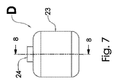
別の実施形態によれば、UV源は、反応器照射チャンバ内の流体と直接接触しているマイクロプラズマランプであり、ランプと流体との間に直接熱経路が提供される。この場合、流体がランプを冷却する。図7および図8に示す実施形態では、照射装置Dは、チャンバに出入りする流体の流れのための入口ポート24と出口ポート25とを有する3次元照射チャンバ23を含む。マイクロプラズマランプのUV放射源26は、照射チャンバ23の内部に放射を提供する。マイクロプラズマランプは、チャンバ23内の流体と直接接触しているので、ランプと流体との間に直接熱経路を提供し、それによって、ランプを冷却する。一つの実施形態によれば、マイクロプラズマランプは、照射チャンバ内の流体と直接接触している熱転写材料と熱接続しており、ランプと流体との間に直接熱経路が提供される。熱転写材料は、金属、誘電体、半導体、プラスチック、または任意の他の熱伝導材料であり得る。熱転写材料は、ランプからのUV放射の一部分を反射してもよい。別の実施形態によれば、熱転写材料は、照射チャンバ内の流体と直接接触している別個の熱転写材料と接触しており、ランプと流体との間に熱経路が提供される。これらの場合、流体がランプを冷却する。したがって、図7および図8に示す実施形態を、本明細書で図示および記載されている他の照射装置の照射チャンバとして使用してもよい。
According to another embodiment, the UV source is a microplasma lamp in direct contact with the fluid in the reactor irradiation chamber, providing a direct thermal path between the lamp and the fluid. In this case the fluid cools the lamp. In the embodiment shown in Figures 7 and 8, the irradiation device D includes a three-
別の実施形態によれば、本発明は、複数のUV放射源と、少なくとも1つの入口ポートおよび1つの出口ポートを各々が有する複数の照射チャンバとを提供する。各UV放射源は、主に、単一の照射チャンバに光学結合される。すべての照射チャンバは、任意の照射チャンバを通過するすべての流体が冷却チャンバも通過するように、単一の冷却チャンバに流体結合される。このようにすると、冷却チャンバを通過する流体束は、すべての照射チャンバを通る流体流の合計と等しくなる。さらに、すべてのUV源は、冷却チャンバの内部を介して流体束に熱結合される。 According to another embodiment, the invention provides a plurality of UV radiation sources and a plurality of irradiation chambers each having at least one inlet port and one outlet port. Each UV radiation source is primarily optically coupled to a single irradiation chamber. All irradiation chambers are fluidly coupled to a single cooling chamber such that all fluid passing through any irradiation chamber also passes through the cooling chamber. In this way, the fluid flux through the cooling chamber equals the sum of the fluid flows through all irradiation chambers. Additionally, all UV sources are thermally coupled to the fluid flux through the interior of the cooling chamber.
別の実施形態によれば、本発明は、複数のUV放射源と、少なくとも1つの入口ポートおよび1つの出口ポートを各々が有する複数の照射チャンバとを提供する。各UV放射源は、主に、単一の照射チャンバに光学結合される。すべてのUV放射源は、単一の冷却チャンバに熱結合される。照射チャンバのうちの1つまたは複数は流体接続しており、1つのチャンバの出口は、別のチャンバの入口である。 According to another embodiment, the invention provides a plurality of UV radiation sources and a plurality of irradiation chambers each having at least one inlet port and one outlet port. Each UV radiation source is primarily optically coupled to a single irradiation chamber. All UV radiation sources are thermally coupled to a single cooling chamber. One or more of the irradiation chambers are in fluid connection, the outlet of one chamber being the inlet of another chamber.
別の実施形態によれば、本発明は、複数のUV放射源と、少なくとも1つの入口ポートおよび1つの出口ポートを各々が有する複数の照射チャンバとを提供する。各UV放射源は、主に、単一の照射チャンバに光学結合される。UV放射源はすべて、単一の冷却チャンバに熱結合される。照射チャンバのうちの1つまたは複数は流体接続しており、1つのチャンバの出口は、別のチャンバの入口である。さらに、冷却チャンバは、照射チャンバのうちの1つまたは複数に流体接続しており、冷却チャンバの出口は、照射チャンバのうちの1つまたは複数の入口である。 According to another embodiment, the invention provides a plurality of UV radiation sources and a plurality of irradiation chambers each having at least one inlet port and one outlet port. Each UV radiation source is primarily optically coupled to a single irradiation chamber. All UV radiation sources are thermally coupled to a single cooling chamber. One or more of the irradiation chambers are in fluid connection, the outlet of one chamber being the inlet of another chamber. Further, the cooling chamber is fluidly connected to one or more of the irradiation chambers, and the exit of the cooling chamber is the entrance of one or more of the irradiation chambers.
上述の実施形態によれば、複数の照射チャンバは、任意の照射チャンバを通過するすべての流体が冷却チャンバも通過するように、単一の冷却チャンバに流体結合される。複数の照射チャンバを単一の冷却チャンバに流体結合して単一のユニットを形成するのと同様に、これらの個々のユニットのセットを、並列または直列に組み合わせて配列してもよく、各ユニットへの入口は、入口における総流量(並列の場合)または全体の流量(直接の場合)の一部、あるいは各ユニットの直接構成および並列構成の混合を構成する。 According to the above-described embodiments, multiple irradiation chambers are fluidly coupled to a single cooling chamber such that all fluid passing through any irradiation chamber also passes through the cooling chamber. Similar to multiple irradiation chambers being fluidly coupled to a single cooling chamber to form a single unit, sets of these individual units may be arranged in parallel or series combinations, each unit The inlets to make up the total flow rate (parallel case) or part of the total flow rate (direct case) at the inlets, or a mixture of direct and parallel configurations of each unit.
図9および図10に示す実施形態によれば、照射装置Eは、3つの3次元チャンバ、2つの照射チャンバ31、および冷却チャンバ27を含む。各チャンバは、チャンバに出入りする流体の流れのための入口ポートと出口ポートとを有する。各照射チャンバ31は、チャンバに流入する流体流のための入口ポート30と、チャンバから流出する流体流のための出口ポート28とを有する。冷却チャンバ27は、チャンバに流入する流体流のための入口ポート29と、チャンバから流出する流体流のための2つの出口ポート30とを有する。冷却チャンバ27と照射チャンバ31とは、流体接続および流体連通しており、ポート30は、冷却チャンバの出口ポートとしても、照射チャンバの入口ポートとしても機能する。UV放射源34は、照射チャンバ31の内部に放射を提供する。放射源は、冷却チャンバ27に熱接続している。この熱接続は、少なくとも1つの熱交換機構の背面および/または前面の間にあり、各放射源と冷却チャンバ内の流体とに熱接続または熱結合されている。一つの実施形態によれば、熱交換機構は、ヒートシンク33を介している。単一の石英光学窓32は、照射チャンバ内の流体から石英光学窓を保護するように、各UV放射源34の上に配置される。UV放射源は、熱交換機構と窓との間に封止されており、それにより、窓は、消毒システムのための圧力容器の一部分として、かつ、UV放射源を照射チャンバ内の流体から分離するために機能する。前述のように、各UV放射源34は、主に、単一の照射チャンバ31に光学結合される。UV放射源はすべて、単一の冷却チャンバ27に熱結合される。照射チャンバ31は、冷却チャンバの出口30は照射チャンバの入口なので、冷却チャンバ27と互いに流体接続および流体連通している。
According to the embodiment shown in FIGS. 9 and 10, the irradiation device E comprises three three-dimensional chambers, two
別の実施形態によれば、UV源から流体束への熱転写は、チャンバの表面に組み込まれており、かつ、そのチャンバ内の流体束と熱接触している公称的に平坦な表面による伝導熱転写を介して実現される。たとえば、図2および図10に示した実施形態では、UV源から冷却チャンバ内の流体への熱転写は、照射チャンバの外面および冷却チャンバの内面に組み込まれており、かつ、冷却チャンバ内の流体束と熱接触しているヒートシンクの公称的に平坦な表面による伝導熱転写を介して実現される。 According to another embodiment, the thermal transfer from the UV source to the fluid flux is conductive thermal transfer by means of a nominally flat surface incorporated into the surface of the chamber and in thermal contact with the fluid flux within the chamber. is realized through For example, in the embodiments shown in Figures 2 and 10, thermal transfer from the UV source to the fluid in the cooling chamber is incorporated into the exterior surface of the irradiation chamber and the interior surface of the cooling chamber, and the fluid flux within the cooling chamber is is accomplished via conductive heat transfer by a nominally flat surface of the heat sink in thermal contact with the
別の実施形態によれば、UV源から流体束への熱転写は、流体束のうちのいくつかまたはすべての流路に配置された多孔質構造による伝導熱転写を介して実現される。多孔質構造は、流体束への効率的な伝導熱転写を行うために表面積が最大になるように設計されていてもよい。伝導熱転写を最大化するために使用される多孔質構造は、流体束の乱流混合および/または層流特性を促進し得る。 According to another embodiment, thermal transfer from the UV source to the fluid bundle is achieved via conductive thermal transfer through porous structures placed in the flow paths of some or all of the fluid bundles. The porous structure may be designed to maximize surface area for efficient conductive heat transfer to the fluid flux. Porous structures used to maximize conductive heat transfer can promote turbulent mixing and/or laminar flow characteristics of the fluid flux.
本発明の一つの実施形態によれば、2つの3次元チャンバは、チャンバに出入りする流体の流れのための少なくとも1つの入口ポートと少なくとも1つの出口ポートとを有する。UV源は、マイクロプラズマランプなどの平坦な光源であり、両側からUV放射を射出する。UV源は照射チャンバと冷却チャンバとの間に位置しており、両方のチャンバに放射を提供する。一つの実施形態によれば、2つのチャンバは流体接続しており、チャンバのうちの一方の入口が、他方のチャンバの出口となる。別の実施形態によれば、平坦なUV源の各面が各チャンバの側壁の一部分として機能する。 According to one embodiment of the invention, the two three-dimensional chambers have at least one inlet port and at least one outlet port for fluid flow into and out of the chambers. A UV source is a flat light source, such as a microplasma lamp, which emits UV radiation from both sides. A UV source is positioned between the irradiation chamber and the cooling chamber and provides radiation to both chambers. According to one embodiment, the two chambers are fluidly connected and the inlet of one of the chambers is the outlet of the other chamber. According to another embodiment, each face of the flat UV source serves as part of the sidewall of each chamber.
次に、図11および図12に示される実施形態を参照すると、照射装置Fは、チャンバに出入りする流体の流れのための入口ポートと出口ポートとを各々が有する2つの3次元チャンバ37および38を含む。照射チャンバ37は、チャンバに流入する流体流のための入口ポート40と、チャンバから流出する流体流のための出口ポート41とを有する。冷却チャンバ38は、チャンバに流入する流体流のための入口ポート39と、チャンバから流出する流体流のための出口ポート40とを有する。冷却チャンバ38と照射チャンバ37とは、流体接続および流体連通しており、ポート40は、冷却チャンバの出口ポートおよび照射チャンバの入口ポートとして機能する。平坦なUV放射源42は、照射チャンバ37の内部および冷却チャンバ38の内部に放射を提供するマイクロプラズマランプである。UV源は照射チャンバと冷却チャンバとの間に位置しており、両方のチャンバに放射を提供する。平坦なUV源の各面が各チャンバの側壁の一部分として機能する。UV放射源42は、照射チャンバおよび冷却チャンバ内の流体からUV放射源を保護するように、両側を覆う石英スリーブまたは光学窓を有する。UV放射源は、窓の間に封止されており、それにより、窓は、消毒システムのための圧力容器の一部分とし、かつ、UV放射源を照射チャンバ内の流体から分離するために機能する。
11 and 12, the irradiation device F comprises two three-
一つの実施形態によれば、照射チャンバ37は、UV源からのUV放射を原則的に反射する材料で構築され、冷却チャンバ38は、UV放射を原則的に吸収する材料で構築されている。別の実施形態によれば、照射チャンバ37と冷却チャンバ38の両方が、UV源からのUV放射線を原則的に反射する材料で構築される。別の実施形態によれば、照射チャンバ37と冷却チャンバ38の両方が、UV源からのUV放射を原則的に吸収する材料で構築される。
According to one embodiment, the
本発明の別の実施形態によれば、本明細書に記載されるUV源は、図13および図14に示すUVエミッタアセンブリGなどのUVエミッタを備えていてもよい。UVエミッタ45は、金属コアプリント回路基板などの熱転写材料または導体44とUV透過性窓47との間にUVエミッタを部分的または完全に封入する、環境封止されたハウジングの内部に埋め込まれている。別の実施形態によれば、封止されたハウジングは、窓47などの原則的にUV透過性窓と、原則的に熱伝導性のカップ43などのヒートシンクを備えており、これらを組み合わせて、回路基板上の1つまたは複数のUV LEDが配置され、かつ、カップに熱接続している、封入容積を形成する。ポッティング化合物48は、熱伝導性カップと窓との間の隙間を埋め、LEDの周囲のキープアウト領域46が小さくなる。一つの実施形態によれば、熱伝導性カップは単一の金属シートの変形によって作製される。熱伝導性カップは、電気接続が入る、および/または出るための、並びに/あるいは液体ポッティング化合物の注入のための1つまたは複数のポートを有してもよい。別の実施形態によれば、熱伝導性カップは、UVエミッタとの熱転写を原則的に意図する少なくとも1つの面を備える。
According to another embodiment of the invention, the UV sources described herein may comprise a UV emitter such as UV emitter assembly G shown in FIGS. 13 and 14. FIG. The
本発明の他の実施形態によれば、光学的に透明な窓は石英またはサファイア、あるいは原則的にUVに透明なポリマーで作製される。ポッティング化合物は、原則的に、熱伝導性カップ内に光学的に透明な窓を保持してもよく、アセンブリの構造的構成要素として機能してもよい。UVエミッタは、基板に実装されたUV放射源を備えてもよく、制御システムがさらに基板に実装されている。UV放射源は、LED、プラズマ放電源、または固体蛍光体射出デバイスのうちの少なくとも1つまたはそれらの組み合わせを備えていてもよい。基板はプリント回路基板を備えていてもよい。基板は、UV放射源と外部熱リザーバとの間に効率的な熱経路を生成するように設計されていてもよい。基板は、ポッティング化合物とUV放射源との接触を防止する手段を提供してもよい。基板は、UV放射源と光学的に透明な窓との相対的な位置決めを規定する手段を提供してもよい。制御システムは、定電流ソースまたは定電流シンクを備えていてもよい。 According to another embodiment of the invention, the optically transparent window is made of quartz or sapphire, or an essentially UV transparent polymer. The potting compound may, in principle, hold the optically transparent window within the thermally conductive cup and may serve as a structural component of the assembly. The UV emitter may comprise a UV radiation source mounted on a substrate, with a control system further mounted on the substrate. The UV radiation source may comprise at least one or a combination of an LED, a plasma discharge source, or a solid state phosphor emission device. The substrate may comprise a printed circuit board. The substrate may be designed to create an efficient thermal path between the UV radiation source and the external heat reservoir. The substrate may provide a means of preventing contact between the potting compound and the UV radiation source. The substrate may provide means for defining the relative positioning of the UV radiation source and the optically transparent window. The control system may have a constant current source or a constant current sink.
本発明は、特定の実施形態またはその実施例を参照して本明細書に例示および説明されているが、当業者には、他の実施形態および実施例が同様の機能を実行し得ること、および/または同様の結果を達成し得ることが容易に明らかになるであろう。同様に、開示された技術の他の応用例が可能であることが明らかになるであろう。かかる同等の実施形態、実施例、および応用例はすべて、本発明の趣旨および範囲に含まれ、添付の請求項により網羅されることが意図される。 Although the present invention has been illustrated and described herein with reference to particular embodiments or examples thereof, it will be appreciated by those skilled in the art that other embodiments and examples may perform similar functions; and/or similar results can be achieved. Likewise, it will become apparent that other applications of the disclosed technique are possible. All such equivalent embodiments, examples, and applications are intended to be included within the spirit and scope of the present invention and covered by the following claims.
Claims (22)
照射対象の物質を含有する流体のための複数の照射チャンバであって、当該複数の照射チャンバのそれぞれが、当該照射チャンバに流入する流体流のための少なくとも1つの入口ポート、および当該照射チャンバから流出する流体流のための少なくとも1つの出口ポートを有する、複数の照射チャンバと、
単一の冷却チャンバであって、当該冷却チャンバは、当該冷却チャンバに流入する流体流のための少なくとも1つの入口ポート、および当該冷却チャンバから流出する流体流のための少なくとも1つの出口ポートを有する、単一の冷却チャンバと、
前記複数の照射チャンバのそれぞれに結合され、前記複数の照射チャンバのそれぞれの内部の流体流を直接照射する、1つまたは複数のUV放射源と、
前記1つまたは複数のUV放射源のそれぞれおよび前記単一の冷却チャンバ内部の流体流に熱結合された少なくとも1つの熱交換機構と、
を備え、
前記複数の照射チャンバのそれぞれおよび前記単一の冷却チャンバは、前記UV放射源からのUV照射を部分的に透過させる壁を共有し、当該壁をもって、前記単一の冷却チャンバの内部表面の少なくとも一部分は、前記複数の照射チャンバのそれぞれの外部表面の少なくとも一部分を含むものとされ、前記単一の冷却チャンバは、前記複数の照射チャンバのそれぞれと流体連通しているものである、
照射装置。 An irradiation device,
A plurality of irradiation chambers for a fluid containing a substance to be irradiated , each of the plurality of irradiation chambers having at least one inlet port for fluid flow entering the irradiation chamber and from the irradiation chamber. a plurality of irradiation chambers having at least one exit port for an exiting fluid stream;
A single cooling chamber, the cooling chamber having at least one inlet port for fluid flow into the cooling chamber and at least one outlet port for fluid flow out of the cooling chamber. , a single cooling chamber, and
one or more UV radiation sources coupled to each of the plurality of irradiation chambers to directly irradiate a fluid stream within each of the plurality of irradiation chambers ;
at least one heat exchange mechanism thermally coupled to each of said one or more UV radiation sources and to fluid flow within said single cooling chamber;
with
Each of the plurality of irradiation chambers and the single cooling chamber share a wall partially transparent to UV irradiation from the UV radiation source, with the wall defining at least an interior surface of the single cooling chamber. a portion comprising at least a portion of an exterior surface of each of said plurality of irradiation chambers, said single cooling chamber being in fluid communication with each of said plurality of irradiation chambers;
Irradiation device.
照射対象の物質を含有する流体のための少なくとも1つの照射チャンバであって、当該照射チャンバが、前記照射チャンバに流入する流体流のための少なくとも1つの入口ポート、および前記照射チャンバから流出する流体流のための少なくとも1つの出口ポートを有する、照射チャンバと、
少なくとも1つの冷却チャンバであって、前記冷却チャンバは、前記冷却チャンバに流入する流体流のための少なくとも1つの入口ポート、および前記冷却チャンバから流出する流体流のための少なくとも1つの出口ポートを有する、冷却チャンバと、
前記少なくとも1つの照射チャンバに結合され、前記少なくとも1つの照射チャンバ内部の流体流を直接照射する、1つまたは複数のUV放射源と、
前記1つまたは複数のUV放射源および前記少なくとも1つの冷却チャンバ内部の流体流に熱結合された少なくとも1つの熱交換機構と、
を備え、
前記少なくとも1つの照射チャンバおよび前記少なくとも1つの冷却チャンバは、前記UV放射源からのUV照射を部分的に透過させる壁を共有し、当該壁をもって、前記少なくとも1つの冷却チャンバの内部表面の少なくとも一部分は、前記少なくとも1つの照射チャンバの外部表面の少なくとも一部分を含み、前記少なくとも1つの冷却チャンバは、前記少なくとも1つの照射チャンバと流体連通しているものであり、
前記1つまたは複数のUV放射源からの前記UV放射の一部分を少なくとも1つの冷却チャンバの表面へと透過して、前記表面でのバイオフィルム形成を抑制する、
照射装置。 An irradiation device,
at least one irradiation chamber for a fluid containing a substance to be irradiated, said irradiation chamber having at least one inlet port for fluid flow entering said irradiation chamber and fluid exiting said irradiation chamber an irradiation chamber having at least one exit port for flow;
At least one cooling chamber, said cooling chamber having at least one inlet port for fluid flow into said cooling chamber and at least one outlet port for fluid flow out of said cooling chamber. , a cooling chamber, and
one or more UV radiation sources coupled to said at least one irradiation chamber to directly irradiate a fluid stream within said at least one irradiation chamber ;
at least one heat exchange mechanism thermally coupled to the one or more UV radiation sources and the fluid flow within the at least one cooling chamber;
with
The at least one irradiation chamber and the at least one cooling chamber share a wall partially transparent to UV irradiation from the UV radiation source, with the wall at least a portion of the interior surface of the at least one cooling chamber. comprises at least a portion of an exterior surface of said at least one irradiation chamber, said at least one cooling chamber being in fluid communication with said at least one irradiation chamber;
transmitting a portion of the UV radiation from the one or more UV radiation sources to a surface of at least one cooling chamber to inhibit biofilm formation on the surface;
Irradiation device.
照射対象の物質を含有する流体のための少なくとも1つの照射チャンバであって、当該照射チャンバが、前記照射チャンバに流入する流体流のための少なくとも1つの入口ポート、および前記照射チャンバから流出する流体流のための少なくとも1つの出口ポートを有する、照射チャンバと、
少なくとも1つの冷却チャンバであって、前記冷却チャンバは、前記冷却チャンバに流入する流体流のための少なくとも1つの入口ポート、および前記冷却チャンバから流出する流体流のための少なくとも1つの出口ポートを有する、冷却チャンバと、
前記少なくとも1つの照射チャンバに結合され、前記少なくとも1つの照射チャンバ内部の流体流を直接照射する、1つまたは複数のUV放射源と、
前記1つまたは複数のUV放射源および前記少なくとも1つの冷却チャンバ内部の流体流に熱結合された少なくとも1つの熱交換機構と、
を備え、
前記少なくとも1つの照射チャンバおよび前記少なくとも1つの冷却チャンバは、前記UV放射源からのUV照射を部分的に透過させる壁を共有し、当該壁をもって、前記少なくとも1つの冷却チャンバの内部表面の少なくとも一部分は、前記少なくとも1つの照射チャンバの外部表面の少なくとも一部分を含むものとされ、前記少なくとも1つの冷却チャンバは、前記少なくとも1つの照射チャンバと流体連通しているものである、
照射装置。 An irradiation device,
at least one irradiation chamber for a fluid containing a substance to be irradiated, said irradiation chamber having at least one inlet port for fluid flow entering said irradiation chamber and fluid exiting said irradiation chamber an irradiation chamber having at least one exit port for flow;
At least one cooling chamber, said cooling chamber having at least one inlet port for fluid flow into said cooling chamber and at least one outlet port for fluid flow out of said cooling chamber. , a cooling chamber, and
one or more UV radiation sources coupled to said at least one irradiation chamber to directly irradiate a fluid stream within said at least one irradiation chamber ;
at least one heat exchange mechanism thermally coupled to the one or more UV radiation sources and the fluid flow within the at least one cooling chamber;
with
The at least one irradiation chamber and the at least one cooling chamber share a wall partially transparent to UV irradiation from the UV radiation source, with the wall at least a portion of the interior surface of the at least one cooling chamber. comprises at least a portion of an exterior surface of said at least one irradiation chamber, said at least one cooling chamber being in fluid communication with said at least one irradiation chamber;
Irradiation device.
(1)照射装置を用意する工程であって、前記照射装置が、
照射対象の物質を含有する流体のための少なくとも1つの照射チャンバであって、前記照射チャンバは、前記照射チャンバに流入する流体流のための少なくとも1つの入口ポート、および前記照射チャンバから流出する流体流のための少なくとも1つの出口ポートを有する、照射チャンバと、
少なくとも1つの冷却チャンバであって、前記冷却チャンバは、前記冷却チャンバに流入する流体流のための少なくとも1つの入口ポート、および前記冷却チャンバから流出する流体流のための少なくとも1つの出口ポートを有する、冷却チャンバと、
前記少なくとも1つの照射チャンバに結合され、前記少なくとも1つの照射チャンバ内部の流体流を直接照射する、1つまたは複数のUV放射源と、
前記1つまたは複数のUV放射源および前記少なくとも1つの冷却チャンバ内部の流体流に熱結合された少なくとも1つの熱交換機構とを備え、
前記少なくとも1つの照射チャンバおよび前記少なくとも1つの冷却チャンバは、前記UV放射源からのUV照射を部分的に透過させる壁を共有し、当該壁をもって、前記少なくとも1つの冷却チャンバの内部表面の少なくとも一部分は、前記少なくとも1つの照射チャンバの外部表面の少なくとも一部分を含むものとされ、前記少なくとも1つの冷却チャンバは、前記少なくとも1つの照射チャンバと流体連通しているものである工程と、
(2)前記照射装置を使用して、前記照射対象の物質を含有している流体を照射する工程と、
を含む、流体の照射方法。 A method of irradiating a fluid containing a substance to be irradiated located in an irradiation chamber, the method comprising:
(1) A step of preparing an irradiation device, wherein the irradiation device
at least one irradiation chamber for a fluid containing a substance to be irradiated, said irradiation chamber comprising at least one inlet port for fluid flow entering said irradiation chamber and fluid exiting said irradiation chamber an irradiation chamber having at least one exit port for flow;
At least one cooling chamber, said cooling chamber having at least one inlet port for fluid flow into said cooling chamber and at least one outlet port for fluid flow out of said cooling chamber. , a cooling chamber, and
one or more UV radiation sources coupled to said at least one irradiation chamber to directly irradiate a fluid stream within said at least one irradiation chamber ;
at least one heat exchange mechanism thermally coupled to the one or more UV radiation sources and the fluid flow within the at least one cooling chamber;
The at least one irradiation chamber and the at least one cooling chamber share a wall partially transparent to UV irradiation from the UV radiation source, with the wall at least a portion of the interior surface of the at least one cooling chamber. comprises at least a portion of an exterior surface of said at least one irradiation chamber, said at least one cooling chamber being in fluid communication with said at least one irradiation chamber;
(2) using the irradiation device to irradiate a fluid containing the substance to be irradiated;
A method of irradiating a fluid, comprising:
(1)照射装置を用意する工程であって、前記照射装置が、
照射対象の物質を含有する流体のための少なくとも1つの照射チャンバであって、前記照射チャンバは、前記照射チャンバに流入する流体流のための少なくとも1つの入口ポート、および前記照射チャンバから流出する流体流のための少なくとも1つの出口ポートを有する、照射チャンバと、
少なくとも1つの冷却チャンバであって、前記冷却チャンバは、前記冷却チャンバに流入する流体流のための少なくとも1つの入口ポート、および前記冷却チャンバから流出する流体流のための少なくとも1つの出口ポートを有する、冷却チャンバと、
前記少なくとも1つの照射チャンバに結合され、当該少なくとも1つの照射チャンバの内部の流体流を直接照射する、1つまたは複数のUV放射源と、
前記1つまたは複数のUV放射源および前記少なくとも1つの冷却チャンバ内部の流体流に熱結合された少なくとも1つの熱交換機構と、
を備え、
前記少なくとも1つの照射チャンバおよび前記少なくとも1つの冷却チャンバは、前記UV放射源からのUV照射を部分的に透過させる壁を共有しているものである工程と、
(2)前記照射装置を使用して、前記照射対象物質を含有する流体を照射する工程と
を含み、
前記1つまたは複数のUV放射源からの前記放射の一部分を前記少なくとも1つの冷却チャンバの表面へと透過して、前記表面でのバイオフィルム形成を抑制する、流体の照射方法。 A method of irradiating a fluid containing a substance to be irradiated located in an irradiation chamber, the method comprising:
(1) A step of preparing an irradiation device, wherein the irradiation device
at least one irradiation chamber for a fluid containing a substance to be irradiated, said irradiation chamber comprising at least one inlet port for fluid flow entering said irradiation chamber and fluid exiting said irradiation chamber an irradiation chamber having at least one exit port for flow;
At least one cooling chamber, said cooling chamber having at least one inlet port for fluid flow into said cooling chamber and at least one outlet port for fluid flow out of said cooling chamber. , a cooling chamber, and
one or more UV radiation sources coupled to the at least one irradiation chamber to directly irradiate a fluid stream within the at least one irradiation chamber ;
at least one heat exchange mechanism thermally coupled to the one or more UV radiation sources and the fluid flow within the at least one cooling chamber;
with
wherein the at least one irradiation chamber and the at least one cooling chamber share walls that are partially transparent to UV irradiation from the UV radiation source ;
(2) using the irradiation device to irradiate the fluid containing the substance to be irradiated;
A method of irradiating a fluid comprising transmitting a portion of said radiation from said one or more UV radiation sources to a surface of said at least one cooling chamber to inhibit biofilm formation on said surface.
照射対象の物質を含有する流体のための少なくとも1つの照射チャンバであって、前記照射チャンバは、前記照射チャンバに流入する流体流のための少なくとも1つの入口ポート、および前記照射チャンバから流出する流体流のための少なくとも1つの出口ポートを有する、照射チャンバと、
少なくとも1つの冷却チャンバであって、前記冷却チャンバは、前記冷却チャンバに流入する流体流のための少なくとも1つの入口ポート、および前記冷却チャンバから流出する流体流のための少なくとも1つの出口ポートを有する、冷却チャンバと、
前記少なくとも1つの照射チャンバに結合され、当該少なくとも1つの照射チャンバの内部の流体流を直接照射する、1つまたは複数のUV放射源と、
前記1つまたは複数のUV放射源および前記少なくとも1つの冷却チャンバ内部の流体流に熱結合された少なくとも1つの熱交換機構と
を備え、
前記照射チャンバおよび前記冷却チャンバは、前記UV放射源からのUV照射を部分的に透過させる壁を共有し、当該壁をもって、前記1つまたは複数のUV放射源からの前記放射の一部分を前記少なくとも1つの冷却チャンバの表面へと透過して、前記表面でのバイオフィルム形成を抑制する、照射装置。 An irradiation device,
at least one irradiation chamber for a fluid containing a substance to be irradiated, said irradiation chamber comprising at least one inlet port for fluid flow entering said irradiation chamber and fluid exiting said irradiation chamber an irradiation chamber having at least one exit port for flow;
At least one cooling chamber, said cooling chamber having at least one inlet port for fluid flow into said cooling chamber and at least one outlet port for fluid flow out of said cooling chamber. , a cooling chamber, and
one or more UV radiation sources coupled to the at least one irradiation chamber to directly irradiate a fluid stream within the at least one irradiation chamber ;
at least one heat exchange mechanism thermally coupled to the one or more UV radiation sources and the fluid flow within the at least one cooling chamber;
The irradiation chamber and the cooling chamber share a wall that is partially transparent to UV irradiation from the UV radiation sources, with the walls transmitting a portion of the radiation from the one or more UV radiation sources to the at least An irradiation device that penetrates to a surface of one of the cooling chambers to inhibit biofilm formation on said surface.
Priority Applications (1)
| Application Number | Priority Date | Filing Date | Title |
|---|---|---|---|
| JP2022096738A JP7462703B2 (en) | 2017-08-11 | 2022-06-15 | Apparatus and method for irradiation |
Applications Claiming Priority (3)
| Application Number | Priority Date | Filing Date | Title |
|---|---|---|---|
| US201762544214P | 2017-08-11 | 2017-08-11 | |
| US62/544,214 | 2017-08-11 | ||
| PCT/US2018/046184 WO2019032943A1 (en) | 2017-08-11 | 2018-08-10 | Apparatus and method for irradiation |
Related Child Applications (1)
| Application Number | Title | Priority Date | Filing Date |
|---|---|---|---|
| JP2022096738A Division JP7462703B2 (en) | 2017-08-11 | 2022-06-15 | Apparatus and method for irradiation |
Publications (3)
| Publication Number | Publication Date |
|---|---|
| JP2020530384A JP2020530384A (en) | 2020-10-22 |
| JP2020530384A5 JP2020530384A5 (en) | 2021-09-30 |
| JP7157137B2 true JP7157137B2 (en) | 2022-10-19 |
Family
ID=65271893
Family Applications (2)
| Application Number | Title | Priority Date | Filing Date |
|---|---|---|---|
| JP2020506342A Active JP7157137B2 (en) | 2017-08-11 | 2018-08-10 | Apparatus and method for irradiation |
| JP2022096738A Active JP7462703B2 (en) | 2017-08-11 | 2022-06-15 | Apparatus and method for irradiation |
Family Applications After (1)
| Application Number | Title | Priority Date | Filing Date |
|---|---|---|---|
| JP2022096738A Active JP7462703B2 (en) | 2017-08-11 | 2022-06-15 | Apparatus and method for irradiation |
Country Status (8)
| Country | Link |
|---|---|
| US (4) | US10994036B2 (en) |
| EP (1) | EP3665128A4 (en) |
| JP (2) | JP7157137B2 (en) |
| KR (2) | KR20220107086A (en) |
| CN (2) | CN111201201B (en) |
| AU (1) | AU2018313244A1 (en) |
| CA (1) | CA3072765A1 (en) |
| WO (1) | WO2019032943A1 (en) |
Families Citing this family (10)
| Publication number | Priority date | Publication date | Assignee | Title |
|---|---|---|---|---|
| JP7157137B2 (en) * | 2017-08-11 | 2022-10-19 | アクイセンス テクノロジーズ エルエルシー | Apparatus and method for irradiation |
| US11117816B2 (en) | 2018-08-13 | 2021-09-14 | Geberit International Ag | Water disinfecting module, systems and methods |
| JP7363269B2 (en) * | 2019-09-24 | 2023-10-18 | 東芝ライテック株式会社 | fluid sterilizer |
| CN112551634A (en) * | 2019-09-26 | 2021-03-26 | 辽宁生态工程职业学院 | Method for treating FOX-7 synthetic wastewater by using zero-dimensional carbon-based nano material |
| US10894726B1 (en) | 2020-02-12 | 2021-01-19 | Aquisense Technologies, Llc | Water disinfecting module, systems and methods |
| US20210308288A1 (en) * | 2020-04-01 | 2021-10-07 | Gerald Ho Kim | Portable Self-Contained Disinfection Device |
| JP7415905B2 (en) | 2020-12-08 | 2024-01-17 | 三菱電機株式会社 | Sterilization equipment and hot water supply equipment |
| EP4104868A1 (en) | 2021-06-17 | 2022-12-21 | Volvo Truck Corporation | A disinfection system for a motorized vehicle |
| US20230071898A1 (en) | 2021-09-03 | 2023-03-09 | Aquisense Technologies, Llc | Apparatus and method for irradiation |
| US20230212038A1 (en) * | 2022-01-05 | 2023-07-06 | Access Business Group International Llc | Water treatment system |
Citations (7)
| Publication number | Priority date | Publication date | Assignee | Title |
|---|---|---|---|---|
| JP2002291854A (en) | 2001-03-29 | 2002-10-08 | Ngk Insulators Ltd | Dehumidifying/deodorizing equipment |
| JP2002291853A (en) | 2001-03-29 | 2002-10-08 | Ngk Insulators Ltd | Dehumidifying/deodorizing equipment |
| JP2015174026A (en) | 2014-03-14 | 2015-10-05 | 日機装株式会社 | light irradiation device |
| JP2017051887A (en) | 2015-09-07 | 2017-03-16 | 日機装株式会社 | Sterilizer |
| JP2017051290A (en) | 2015-09-07 | 2017-03-16 | 日機装株式会社 | Sterilizing apparatus |
| US20170156378A1 (en) | 2014-07-18 | 2017-06-08 | Nestec S.A. | Method and apparatus for purifying liquid |
| JP2017121592A (en) | 2016-01-04 | 2017-07-13 | 株式会社東芝 | Ultraviolet irradiation unit and ultraviolet irradiation device |
Family Cites Families (33)
| Publication number | Priority date | Publication date | Assignee | Title |
|---|---|---|---|---|
| GB1515086A (en) | 1975-05-22 | 1978-06-21 | Sun Chemical Corp | Ultraviolet lamp assembly |
| US5372781A (en) | 1992-02-18 | 1994-12-13 | Solarchem Enterprises Inc. | UV reactor assembly with improved lamp cooling means |
| EP0588228A1 (en) | 1992-09-12 | 1994-03-23 | Ralf Ritter | Sterilizable container for single medical and surgical sets and instruments |
| DE19517039C2 (en) | 1994-10-25 | 2002-07-18 | Guenther O Schenck | Device for oxidative photopurification |
| EP1842561A1 (en) * | 1995-07-14 | 2007-10-10 | CAF - DCF cvba - scrl | Method and device for UV-inactivation of virus in blood products |
| US20020102253A1 (en) * | 1997-02-25 | 2002-08-01 | Mynott Tracey Lehanne | Component of bromelain |
| US6054097A (en) | 1998-08-03 | 2000-04-25 | Innovatech | Expanding plasma emission source microorganism inactivation system |
| WO2000068152A1 (en) | 1999-05-05 | 2000-11-16 | Milton Paul Pinel | Method and apparatus for fluid treatment by uv-radiation |
| DE102004015700A1 (en) * | 2004-03-29 | 2005-11-03 | Platsch Gmbh & Co.Kg | Flat UV light source |
| CN102557313A (en) * | 2004-04-15 | 2012-07-11 | 特洛伊人技术公司 | Water treatment appliance and treatment cartridge used in fluid treatment system |
| US7030391B2 (en) * | 2004-06-04 | 2006-04-18 | Cfm Corporation | Ultraviolet sterilization device |
| US7993580B2 (en) | 2004-08-24 | 2011-08-09 | Baxter International Inc. | Methods for the inactivation of microorganisms in biological fluids, flow through reactors and methods of controlling the light sum dose to effectively inactivate microorganisms in batch reactors |
| US20070295012A1 (en) | 2006-06-26 | 2007-12-27 | Applied Materials, Inc. | Nitrogen enriched cooling air module for uv curing system |
| EP2379193B1 (en) | 2008-12-19 | 2018-06-20 | University Of North Carolina At Charlotte | System and method for performing disinfection of a fluid using point radiation source |
| US8481985B2 (en) | 2009-01-29 | 2013-07-09 | S. Edward Neister | Method and apparatus for producing a high level of disinfection in air and surfaces |
| US8980178B2 (en) * | 2009-05-23 | 2015-03-17 | Sensor Electronic Technology, Inc. | Medium treatment using ultraviolet light |
| US8558200B2 (en) * | 2009-08-27 | 2013-10-15 | Air Motion Systems, Inc | Multiple row scalable LED-UV module |
| CN104603914B (en) * | 2012-09-07 | 2017-07-14 | 应用材料公司 | The integrated processing of porous dielectric, polymer-coated substrate and epoxides in multi-chamber vacuum system |
| JP2014083470A (en) * | 2012-10-19 | 2014-05-12 | Nikkiso Co Ltd | Ultraviolet irradiation device and ultraviolet irradiation method |
| JP5496306B2 (en) * | 2012-10-31 | 2014-05-21 | 株式会社トクヤマ | UV sterilizer |
| US11338048B2 (en) * | 2012-12-11 | 2022-05-24 | Aquisense Technologies Llc | Apparatus for irradiation |
| US8622896B1 (en) * | 2013-01-04 | 2014-01-07 | Zafer Termanini | Liquid-cooled light source for endoscopy and irrigation/suction and power supply tubing and method thereof |
| JP6153343B2 (en) * | 2013-02-22 | 2017-06-28 | 国立大学法人埼玉大学 | UV irradiation water treatment equipment |
| JP2014233646A (en) * | 2013-05-30 | 2014-12-15 | 日機装株式会社 | Water purifier |
| US9278870B2 (en) * | 2014-01-21 | 2016-03-08 | Panasonic Corporation | Ultraviolet irradiation apparatus and ultraviolet irradiation method |
| US9499415B2 (en) | 2014-08-14 | 2016-11-22 | Chiyoda Kohan Co., Ltd | Ultraviolet irradiation apparatus |
| US9265876B1 (en) | 2014-10-22 | 2016-02-23 | Hemalux Technologies LLC | Systems and methods for pathogen inactivation in blood using UV irradiation while minimizing heat transfer thereto |
| CN204454717U (en) * | 2014-12-22 | 2015-07-08 | 安徽工程大学 | Effluent treatment plant |
| US9644831B2 (en) | 2015-01-15 | 2017-05-09 | Heraeus Noblelight America Llc | Intelligent manifold assemblies for a light source, light sources including intelligent manifold assemblies, and methods of operating the same |
| JP6373792B2 (en) * | 2015-04-22 | 2018-08-15 | 日機装株式会社 | Sterilizer |
| US10095332B2 (en) * | 2015-07-24 | 2018-10-09 | Apple Inc. | Pixel charging and discharging rate control systems and methods |
| US10207936B2 (en) * | 2016-02-19 | 2019-02-19 | Silanna UV Technologies Pte Ltd | Ultraviolet reactor with planar light source |
| JP7157137B2 (en) | 2017-08-11 | 2022-10-19 | アクイセンス テクノロジーズ エルエルシー | Apparatus and method for irradiation |
-
2018
- 2018-08-10 JP JP2020506342A patent/JP7157137B2/en active Active
- 2018-08-10 CN CN201880059065.XA patent/CN111201201B/en active Active
- 2018-08-10 WO PCT/US2018/046184 patent/WO2019032943A1/en unknown
- 2018-08-10 AU AU2018313244A patent/AU2018313244A1/en active Pending
- 2018-08-10 KR KR1020227025265A patent/KR20220107086A/en not_active Application Discontinuation
- 2018-08-10 KR KR1020207006890A patent/KR102424836B1/en active IP Right Grant
- 2018-08-10 CA CA3072765A patent/CA3072765A1/en active Pending
- 2018-08-10 EP EP18845288.2A patent/EP3665128A4/en active Pending
- 2018-08-10 CN CN202211020272.9A patent/CN115340145A/en not_active Withdrawn
- 2018-08-13 US US16/101,909 patent/US10994036B2/en active Active
- 2018-08-13 US US16/101,890 patent/US10500295B2/en active Active
-
2019
- 2019-11-11 US US16/679,491 patent/US10814024B2/en active Active
-
2021
- 2021-02-15 US US17/176,079 patent/US11633510B2/en active Active
-
2022
- 2022-06-15 JP JP2022096738A patent/JP7462703B2/en active Active
Patent Citations (7)
| Publication number | Priority date | Publication date | Assignee | Title |
|---|---|---|---|---|
| JP2002291854A (en) | 2001-03-29 | 2002-10-08 | Ngk Insulators Ltd | Dehumidifying/deodorizing equipment |
| JP2002291853A (en) | 2001-03-29 | 2002-10-08 | Ngk Insulators Ltd | Dehumidifying/deodorizing equipment |
| JP2015174026A (en) | 2014-03-14 | 2015-10-05 | 日機装株式会社 | light irradiation device |
| US20170156378A1 (en) | 2014-07-18 | 2017-06-08 | Nestec S.A. | Method and apparatus for purifying liquid |
| JP2017051887A (en) | 2015-09-07 | 2017-03-16 | 日機装株式会社 | Sterilizer |
| JP2017051290A (en) | 2015-09-07 | 2017-03-16 | 日機装株式会社 | Sterilizing apparatus |
| JP2017121592A (en) | 2016-01-04 | 2017-07-13 | 株式会社東芝 | Ultraviolet irradiation unit and ultraviolet irradiation device |
Also Published As
| Publication number | Publication date |
|---|---|
| US20190046674A1 (en) | 2019-02-14 |
| JP7462703B2 (en) | 2024-04-05 |
| CA3072765A1 (en) | 2019-02-14 |
| CN115340145A (en) | 2022-11-15 |
| JP2020530384A (en) | 2020-10-22 |
| CN111201201A (en) | 2020-05-26 |
| US11633510B2 (en) | 2023-04-25 |
| US20210162083A1 (en) | 2021-06-03 |
| AU2018313244A1 (en) | 2020-03-05 |
| KR20220107086A (en) | 2022-08-01 |
| US10814024B2 (en) | 2020-10-27 |
| KR102424836B1 (en) | 2022-07-25 |
| WO2019032943A1 (en) | 2019-02-14 |
| US20190046675A1 (en) | 2019-02-14 |
| JP2022120154A (en) | 2022-08-17 |
| US10500295B2 (en) | 2019-12-10 |
| US10994036B2 (en) | 2021-05-04 |
| EP3665128A4 (en) | 2021-04-14 |
| KR20200030619A (en) | 2020-03-20 |
| EP3665128A1 (en) | 2020-06-17 |
| US20200069825A1 (en) | 2020-03-05 |
| CN111201201B (en) | 2022-12-02 |
Similar Documents
| Publication | Publication Date | Title |
|---|---|---|
| JP7157137B2 (en) | Apparatus and method for irradiation | |
| EP2915546B1 (en) | Ultraviolet sterilizer and sterilization method | |
| US9480768B2 (en) | Air sterilization and disinfection method | |
| JP5591305B2 (en) | Ultraviolet light emitting module and ultraviolet irradiation device | |
| US20220395592A1 (en) | Apparatus for irradiation | |
| CA3036345C (en) | Ultraviolet irradiation device and method | |
| JP7035499B2 (en) | Ultraviolet light irradiation sterilizer | |
| US20230071898A1 (en) | Apparatus and method for irradiation | |
| CN216054699U (en) | COB (chip on Board) sterilization light source of UVC (ultraviolet light emitting diode) -LED (light emitting diode) | |
| JP2019201861A (en) | Fluid sterilizer | |
| KR20240052064A (en) | Irradiation device and method | |
| TWI777009B (en) | Heat dissipation module with transparent pipe | |
| WO2019080129A1 (en) | Fluid sterilization device | |
| KR20200081924A (en) | Sterilizing apparatus | |
| JP2023110196A (en) | Light irradiation device | |
| JP2023078423A (en) | Fluid sterilizer | |
| KR20150146344A (en) | stiffening and sterilization apparatus by using UV/LED |
Legal Events
| Date | Code | Title | Description |
|---|---|---|---|
| A521 | Request for written amendment filed |
Free format text: JAPANESE INTERMEDIATE CODE: A523 Effective date: 20210810 |
|
| A621 | Written request for application examination |
Free format text: JAPANESE INTERMEDIATE CODE: A621 Effective date: 20210810 |
|
| A521 | Request for written amendment filed |
Free format text: JAPANESE INTERMEDIATE CODE: A523 Effective date: 20210811 |
|
| A871 | Explanation of circumstances concerning accelerated examination |
Free format text: JAPANESE INTERMEDIATE CODE: A871 Effective date: 20210811 |
|
| A131 | Notification of reasons for refusal |
Free format text: JAPANESE INTERMEDIATE CODE: A131 Effective date: 20211019 |
|
| A521 | Request for written amendment filed |
Free format text: JAPANESE INTERMEDIATE CODE: A523 Effective date: 20220119 |
|
| A02 | Decision of refusal |
Free format text: JAPANESE INTERMEDIATE CODE: A02 Effective date: 20220215 |
|
| A521 | Request for written amendment filed |
Free format text: JAPANESE INTERMEDIATE CODE: A523 Effective date: 20220615 |
|
| C60 | Trial request (containing other claim documents, opposition documents) |
Free format text: JAPANESE INTERMEDIATE CODE: C60 Effective date: 20220615 |
|
| C11 | Written invitation by the commissioner to file amendments |
Free format text: JAPANESE INTERMEDIATE CODE: C11 Effective date: 20220628 |
|
| A911 | Transfer to examiner for re-examination before appeal (zenchi) |
Free format text: JAPANESE INTERMEDIATE CODE: A911 Effective date: 20220815 |
|
| C21 | Notice of transfer of a case for reconsideration by examiners before appeal proceedings |
Free format text: JAPANESE INTERMEDIATE CODE: C21 Effective date: 20220816 |
|
| TRDD | Decision of grant or rejection written | ||
| A01 | Written decision to grant a patent or to grant a registration (utility model) |
Free format text: JAPANESE INTERMEDIATE CODE: A01 Effective date: 20220906 |
|
| A61 | First payment of annual fees (during grant procedure) |
Free format text: JAPANESE INTERMEDIATE CODE: A61 Effective date: 20221006 |
|
| R150 | Certificate of patent or registration of utility model |
Ref document number: 7157137 Country of ref document: JP Free format text: JAPANESE INTERMEDIATE CODE: R150 |