CN115338552B - System and method for controlling edge angle of cylinder of soil covering tank - Google Patents
System and method for controlling edge angle of cylinder of soil covering tank Download PDFInfo
- Publication number
- CN115338552B CN115338552B CN202211269769.4A CN202211269769A CN115338552B CN 115338552 B CN115338552 B CN 115338552B CN 202211269769 A CN202211269769 A CN 202211269769A CN 115338552 B CN115338552 B CN 115338552B
- Authority
- CN
- China
- Prior art keywords
- welding
- cylinder
- jacking
- edge angle
- heat source
- Prior art date
- Legal status (The legal status is an assumption and is not a legal conclusion. Google has not performed a legal analysis and makes no representation as to the accuracy of the status listed.)
- Active
Links
Images


Classifications
-
- B—PERFORMING OPERATIONS; TRANSPORTING
- B23—MACHINE TOOLS; METAL-WORKING NOT OTHERWISE PROVIDED FOR
- B23K—SOLDERING OR UNSOLDERING; WELDING; CLADDING OR PLATING BY SOLDERING OR WELDING; CUTTING BY APPLYING HEAT LOCALLY, e.g. FLAME CUTTING; WORKING BY LASER BEAM
- B23K31/00—Processes relevant to this subclass, specially adapted for particular articles or purposes, but not covered by any single one of main groups B23K1/00 - B23K28/00
- B23K31/003—Processes relevant to this subclass, specially adapted for particular articles or purposes, but not covered by any single one of main groups B23K1/00 - B23K28/00 relating to controlling of welding distortion
-
- G—PHYSICS
- G06—COMPUTING OR CALCULATING; COUNTING
- G06F—ELECTRIC DIGITAL DATA PROCESSING
- G06F30/00—Computer-aided design [CAD]
- G06F30/10—Geometric CAD
- G06F30/17—Mechanical parametric or variational design
-
- G—PHYSICS
- G06—COMPUTING OR CALCULATING; COUNTING
- G06F—ELECTRIC DIGITAL DATA PROCESSING
- G06F30/00—Computer-aided design [CAD]
- G06F30/20—Design optimisation, verification or simulation
- G06F30/23—Design optimisation, verification or simulation using finite element methods [FEM] or finite difference methods [FDM]
-
- G—PHYSICS
- G06—COMPUTING OR CALCULATING; COUNTING
- G06F—ELECTRIC DIGITAL DATA PROCESSING
- G06F2119/00—Details relating to the type or aim of the analysis or the optimisation
- G06F2119/08—Thermal analysis or thermal optimisation
Landscapes
- Engineering & Computer Science (AREA)
- Physics & Mathematics (AREA)
- Theoretical Computer Science (AREA)
- Geometry (AREA)
- General Physics & Mathematics (AREA)
- Computer Hardware Design (AREA)
- Evolutionary Computation (AREA)
- General Engineering & Computer Science (AREA)
- Mathematical Analysis (AREA)
- Mathematical Optimization (AREA)
- Pure & Applied Mathematics (AREA)
- Computational Mathematics (AREA)
- Mechanical Engineering (AREA)
- Butt Welding And Welding Of Specific Article (AREA)
Abstract
The invention provides a system and a method for controlling the edge angle of a cylinder of an earth covering tank. The utility model discloses a long-range analog system establishes barrel solid model, in leading-in transient state hot module, at the surperficial loading gauss heat source of welding seam, the analog welding process, calculate the welding seam temperature field, load the temperature field in the static structure module, calculate the deflection of barrel welding seam department, the controller is based on this deflection and the wrong limit volume of R type laser scanner actual measurement, obtain the deflection recommendation value, and then confirm accurate jacking volume, control the jacking of hydraulic means according to this, carry out the edge angle adjustment, guarantee that welding accomplishes the back barrel edge angle and satisfy the requirement, the blindness of traditional mode to edge angle control and correction has been solved, edge angle control accuracy is improved.
Description
Technical Field
The invention belongs to the technical field of soil covering tank barrel body edge angle control, and particularly relates to a soil covering tank barrel body edge angle control system and method.
Background
The edge angle of the soil covering tank body mainly exists in the butt-joint welding seam, and means that the edge angle greatly influences the appearance quality of the surface of the tank body relative to the deviation of the warp, so that the stress concentration of the welding seam is caused, the bearing capacity of a weldment is reduced, additional bending stress is generated during operation, and the problems of stress corrosion cracking and the like can be caused. Usually, the control requirement of pressure vessel edge angle is carried out according to GB150-2011 standard, and the control to edge angle is mainly concentrated on the board rolling stage in the construction at present, and secondly carries out the inspection control of edge angle after welding, but the inspection of edge angle before the butt welding and in the welding process with control is less relatively, therefore produces the problem that edge angle that causes because of the welding exceeds standard easily.
Disclosure of Invention
Aiming at the defects in the prior art, the invention provides a system and a method for controlling the edge angle of a cylinder of an earth covering tank, which solve the problem of blindness of the traditional method on the control and correction of the edge angle, improve the accuracy of the control of the edge angle, reduce the times of edge angle control tests and improve the manufacturing efficiency and quality of the cylinder.
The present invention achieves the above technical objects by the following technical means.
The utility model provides an earthing jar barrel edge angle control system, includes that the lower surface mounting has the bottom plate of self-propelled wheel that rolls, and surface mounting has hydraulic means and controller on the bottom plate, and the bracing piece is installed to the hydraulic means lateral wall, and the R type laser scanner with controller signal connection is installed at the bracing piece top, and self-propelled wheel that rolls, hydraulic means are controlled by the controller, controller and remote analog system signal connection.
Furthermore, the hydraulic device is controlled by a controller and has two working modes of manual operation and automatic operation, in the automatic mode, the R-type laser scanner detects the misalignment of the cylinder and feeds back the misalignment to the controller, and the controller controls the jacking rod on the hydraulic device to jack according to the welding deformation given by the remote simulation system and the misalignment of the cylinder; under the manual mode, the controller is fed back to after the barrel misalignment volume is surveyed to R type laser scanner, and the display screen of controller shows the testing result, inserts manual hydraulic stem in the hydraulic means by constructor, and the jacking volume of the jacking pole of manual regulation hydraulic means.
The method for controlling the edge angle of the soil covering tank cylinder by using the edge angle control system of the soil covering tank cylinder comprises the following steps:
step 1: the remote simulation system establishes a cylinder welding model based on finite element software, introduces the cylinder welding model into the transient heat calculation module, inputs a Gaussian heat source formula into the APDL module, loads a Gaussian heat source on the surface of each welding seam, simulates the actual welding process, calculates the temperature field of the cylinder welding seam, loads the temperature field into the static structure model, and calculates the welding deformation of the welding seam;
step 2: arranging a ridge angle control system below the barrel on a construction site, detecting the misalignment of the barrel before welding by using an R-type laser scanner, and displaying a detection result on a display screen of a controller to ensure that the assembly quality of the barrel meets the welding requirement;
and step 3: inserting a manual hydraulic rod into a hydraulic device, manually adjusting the hydraulic device, loading corresponding jacking amount to the jacking rod on the hydraulic device, then performing barrel assembly welding, detecting the edge angle of the barrel by using an R-shaped laser scanner after welding is completed, and recording the jacking amount loaded on the barrel if a detection result meets a standard requirement;
and 4, step 4: through a large number of tests, obtaining a plurality of jacking amount data, and establishing a relational expression between the jacking amount and the welding deformation;
and 5: the controller calculates the jacking amount to be applied to the cylinder based on the welding deformation calculated by the remote simulation system, the misalignment of the cylinder detected by the R-type laser scanner and the relation between the jacking amount and the welding deformation, and controls the jacking rod on the hydraulic device to automatically jack.
Further, the gaussian heat source formula in step 1 is:

wherein, which represents the density of the heat source,
 which represents the initial heat source density and,
 the natural constant is represented by a natural constant,
 it is shown that the constant is constant,
 represents the coordinate value on the x axis of the heat source moving point in the global coordinate system,
 represents the coordinate value on the z axis of the heat source moving point in the global coordinate system,
 the speed of the welding is indicated by the indication,
 the time of the movement is indicated,
 indicating the set analysis time per step,
 indicating the radius of the arc.
Further, the calculation formula of the welding deformation amount in the step 1 is as follows:
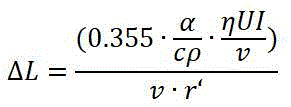
wherein, the amount of the welding deformation is indicated,
 indicating the coefficient of thermal expansion of the material of the barrel,
 the specific heat capacity of the material of the cylinder is shown,
 which represents the density of the material of the cartridge,
 the efficiency of the cladding is shown,
 which is indicative of the welding voltage,
 the welding current is represented by the number of welding cycles,
 the speed of the welding is indicated and,
 the diameter of the solder is shown.
Further, in the step 4, a relation between the jacking amount and the welding deformation amount is as follows: wherein, in the process,
 the amount of jacking is shown as the amount of jacking,
 is a constant.
Further, the specific process of step 5 is as follows: the R-type laser scanner detects the barrel misalignment amount and feeds back to the controller, the remote simulation system calculates the welding deformation amount and feeds back to the controller, the controller obtains the recommended deformation amount according to the welding deformation amount obtained through simulation calculation and the misalignment amount actually measured, then the jacking amount to be applied to the barrel is obtained through calculation according to the relation between the jacking amount and the welding deformation amount, the hydraulic device is controlled to be jacked automatically to achieve the required jacking amount according to the jacking amount, and the edge angle reverse deformation of the barrel is completed.
Further, the specific process of step 1 is as follows:
step 1.1: the remote simulation system establishes a cylinder welding model based on finite element software according to the cylinder and relevant welding parameters;
step 1.2: in finite element software, associating a welding seam module with a cylinder welding model, dividing each welding seam of the cylinder into the welding length in actual welding unit time, and recording the number of the divided welding seams;
step 1.3: guiding the cylinder welding model into a transient heat calculation module, setting materials of the cylinder welding model, confirming a global coordinate system, checking the contact condition between a welding seam module and the cylinder welding model, and confirming the contact relation;
step 1.4: processing the cylinder welding model by adopting a grid-divided sweeping mode;
step 1.5: establishing a plurality of surface sets according to the actual number of welding lines, and setting the ambient temperature, the transient heat source analysis step, the time of the analysis step and the convection coefficient;
step 1.6: inputting a Gaussian heat source formula into an APDL module to obtain a code of the Gaussian heat source, loading the Gaussian heat source on the surface of each welding seam, setting time parameters in each Gaussian heat source according to the time in the step 1.5, setting 'life and death units' in each welding seam according to the welding sequence to simulate the actual welding process, and calculating to obtain a temperature field of the welding seam of the cylinder;
step 1.7: loading the temperature field of the welding seam of the cylinder body into a static structure model, setting an analysis step, analysis time of each step and corresponding constraint conditions and loads, then setting the gravity action and the direction of the cylinder body, setting the contact surface of the roller frame and the cylinder body as a cylindrical support, completing the mechanical calculation of the cylinder body structure based on a welding heat source, and obtaining the welding deformation of the welding seam.
Further, in step 1.4, the structure size of the cylinder is divided into the mesh size of 300mm, the weld structure size is divided into the mesh size of 10mm, and the surface size of the circular cross section at the two ends of the cylinder is divided into the mesh size of 10 mm.
Further, in step 1.5, the ambient temperature is set at 22 ℃ and the time interval of the analysis step is 20s.
The invention has the following beneficial effects:
(1) Compared with the traditional mode of controlling the edge angle at the bottom of the soil covering tank only by experience, the method utilizes finite element software to perform simulation calculation on the welding process of the soil covering tank cylinder body, determines the simulation deformation amount of the cylinder body welding line, calculates to obtain a more accurate jacking amount value by combining the data obtained by detection of the R-shaped laser scanner, automatically controls the hydraulic device to jack up according to the more accurate jacking amount value, and adjusts the edge angle, thereby ensuring that the edge angle of the cylinder body meets the standard requirement after welding is completed; the invention solves the blindness of the traditional mode on controlling and correcting the edge angle, can improve the accuracy of the edge angle control, reduce the times of the edge angle control test and improve the manufacturing efficiency and quality of the cylinder.
(2) The invention can control the edge angle of the soil covering tanks with different sizes under different conditions, and carry out targeted correction, thereby having wide application prospect; the invention can realize detection at any time and automatic correction at any time, and has high intelligent degree; the invention can automatically adjust the radian of the R-type laser scanner according to the shape of the cylinder and is self-adaptive to various cylinder sizes.
(3) The invention can realize the adjustment of an automatic mode and a manual mode, and can also control the edge angle through the manual mode under the out-of-control state of the automatic mode, thereby ensuring the smooth operation of the engineering.
(4) The controller of the invention also has the function of autonomous learning, and can continuously optimize and adjust the edge angle control system.
Drawings
FIG. 1 is a schematic view of a system for controlling the angle of a cylinder of a soil covering tank;
FIG. 2 is a schematic view of the measurement of the edge angle control system of the soil covering tank cylinder;
FIG. 3 is a schematic view of the lifting of the corner angle control system of the soil covering tank.
In the figure: 1-a bottom plate; 2-self-propelled rolling wheels; 3-a manual hydraulic rod; 4-a hydraulic device; 5-a jacking rod; laser scanner type 6-R; 7-a support bar; 8-a controller; 9-remote simulation system; 10-a cylinder body; 11-a roller frame; 12-stay bar.
Detailed Description
The invention will be further described with reference to the following figures and specific examples, without limiting the scope of the invention thereto.
As shown in figure 1, the edge angle control system of the soil covering tank cylinder comprises a bottom plate 1, a self-propelled rolling wheel 2, a manual hydraulic rod 3, a hydraulic device 4, an R-shaped laser scanner 6, a support rod 7, a controller 8 and a remote simulation system 9.
As shown in figure 1, four corners of the lower surface of a bottom plate 1 are respectively provided with a self-propelled rolling wheel 2 controlled by a controller 8, and the self-propelled rolling wheels are used for driving an edge angle control system to integrally move. Surface mounting has hydraulic means 4 and controller 8 on bottom plate 1, and the bracing piece 7 is installed to 4 lateral walls of hydraulic means, and R type laser scanner 6 is installed at bracing piece 7 top, R type laser scanner 6 and 8 signal connection of controller, controller 8 and remote analog system 9 signal connection, and remote analog system 9 mainly simulates out the welding deformation volume of barrel 10 through finite element software.
As shown in fig. 1, the hydraulic device 4 is controlled by a controller 8, and has two working modes, namely a manual working mode and an automatic working mode, in the automatic mode, the R-type laser scanner 6 detects the misalignment of the cylinder 10 and feeds back the misalignment to the controller 8, and the controller 8 controls the hydraulic device 4 to work and the jacking rod 5 to jack according to the welding deformation given by the remote simulation system 9 and the misalignment of the cylinder 10; under the manual mode, R type laser scanner 6 records barrel 10 misalignment volume and feeds back to controller 8, and controller 8 only shows, inserts manual hydraulic stem 3 among hydraulic means 4 by constructor, and the jacking volume of jacking pole 5 of manual regulation hydraulic means 4.
The method for controlling the edge angle based on the soil covering tank barrel edge angle control system comprises the following steps:
step 1: the remote simulation system 9 establishes a cylinder welding model based on finite element software according to parameters such as the size of the cylinder 10, the size of a stay bar 12 in the cylinder 10, the distance between roller frames 11, the position and the size of a weld groove, weld bead arrangement, welding sequence and the like;
step 2: in finite element software, through functions of slicing, freezing, deleting and the like, the welding seam module is associated with the cylinder welding model, so that subsequent heat source transmission is facilitated; then, each welding seam of the cylinder 10 is divided into the welding length in the actual welding unit time, and the number of the divided welding seams is recorded;
and step 3: importing the cylinder welding model into a transient thermal calculation module in finite element software, setting materials of the cylinder welding model, confirming a global coordinate system, checking the contact condition between a welding seam module and the cylinder welding model, and confirming the contact relation;
and 4, step 4: processing the cylinder welding model by adopting a grid-dividing sweeping mode, dividing the size of the structural body of the cylinder 10 by the grid size of 300mm, dividing the size of the structural body of a welding seam by the grid size of 10mm, and dividing the surface size of the circular ring section at two ends of the cylinder 10 by the grid size of 10 mm;
and 5: establishing a plurality of surface sets according to the actual number of welding seams, setting the ambient temperature to be 22 ℃, setting the transient heat source analysis step to be a plurality of steps, setting the time of the analysis step to be 20s, 40s and 60s \8230, 8230and 280s, namely 20s, and then setting convection coefficients of a cylinder welding model, a support rod 12 and a roller frame 11;
step 6: inputting a Gaussian heat source formula shown in the specification into an APDL module of finite element software to obtain codes of Gaussian heat sources, loading the Gaussian heat sources on the surfaces of all welding seams, setting time parameters in each Gaussian heat source according to the time in the step 5, and setting 'life and death units' for all welding seams according to a welding sequence to simulate an actual welding process and calculate to obtain a temperature field of the welding seams of the cylinder 10;

wherein, which represents the density of the heat source,
 the initial heat source density is shown and is obtained by calculation of welding current, voltage, welding speed, heat efficiency and action area,
 which is a representation of a natural constant of,
 representing a constant, typically 1, 2, 3,
 represents the coordinate value of the heat source moving point position on the x axis in the global coordinate system,
 represents the coordinate value on the z axis of the heat source moving point in the global coordinate system,
 the speed of the welding is indicated by the indication,
 which is indicative of the time of the movement,
 indicating the set analysis time per step,
 represents the radius of the arc;
and 7: loading the temperature field of the welding seam of the cylinder 10 into a static structure model in finite element software, setting analysis steps, analysis time of each step and corresponding constraint conditions and loads, and ensuring that the analysis time of each step is consistent with that in a transient thermal calculation module; then setting the gravity action and direction of the cylinder 10, as shown in fig. 2, setting the contact surface of the roller frame 11 and the cylinder 10 as a cylindrical support, completing the structural mechanics calculation of the cylinder 10 based on the welding heat source, and obtaining the welding deformation of the welding seam :
:
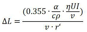
Wherein, the amount of the welding deformation is indicated,
 indicating the coefficient of thermal expansion of the material of the
 barrel 10, indicating the specific heat capacity of the material of the
 cartridge 10, which represents the density of the material of the
 cartridge 10, the efficiency of the cladding is shown,
 which is indicative of the welding voltage,
 the representation of the welding current is shown,
 the speed of the welding is indicated by the indication,
 the diameter of the welding material is shown;
and 8: then, arranging a ridge angle control system below the cylinder 10 on the construction site, and detecting the misalignment amount of the cylinder 10 before welding by using an R-shaped laser scanner 6 in a manual mode as shown in FIG. 2 to ensure that the assembly quality of the cylinder 10 meets the welding requirement;
and step 9: in the manual mode, as shown in fig. 3, the hydraulic device 4 is manually adjusted by using the manual hydraulic rod 3, a certain jacking amount is loaded on the jacking rod 5 of the hydraulic device 4, then the assembly of the cylinder 10 is performed, after the welding is completed, the edge angle of the cylinder 10 is detected by using the R-type laser scanner 6 in the manual mode, and if the detection result meets the standard requirement, the jacking amount loaded on the cylinder 10 is recorded;
step 10: through a large number of experiments, a plurality of jacking amount data are obtained, and a relational expression between the jacking amount and the welding deformation is established ( ) Wherein
 the amount of jacking is shown as the amount of jacking,
 the value of the constant is related to the diameter of the
 cylinder 10, the weight of the cylinder 10, the distance between the roller frames 11 and the thickness of the cylinder 10;
step 11: the edge angle control system automatically controls and adjusts the edge angle of the cylinder 10 in an automatic mode: the R-type laser scanner 6 firstly detects the misalignment amount of the cylinder 10 and feeds the misalignment amount back to the controller 8, the remote simulation system 9 calculates the welding deformation amount and feeds the welding deformation amount back to the controller 8, the controller 8 obtains a recommended deformation amount according to the welding deformation amount obtained by simulation calculation and the misalignment amount actually measured, then according to a relational expression between the jacking amount and the welding deformation amount, the jacking amount to be applied to the cylinder 10 is obtained by calculation, the hydraulic device 4 is controlled to jack up by itself to reach the required jacking amount, therefore, the inverse deformation of the edge angle of the cylinder 10 is completed, and the edge angle of the cylinder 10 after being welded meets the standard requirement.
The examples are preferred embodiments of the present invention, but the present invention is not limited to the above embodiments, and any obvious modifications, substitutions or variations can be made by those skilled in the art without departing from the spirit of the present invention.
Claims (9)
1. The edge angle control system of the cylinder of the soil covering tank is characterized by comprising a bottom plate (1) with a self-propelled rolling wheel (2) arranged on the lower surface, a hydraulic device (4) and a controller (8) arranged on the upper surface of the bottom plate (1), a support rod (7) arranged on the side wall of the hydraulic device (4), an R-type laser scanner (6) in signal connection with the controller (8) arranged at the top of the support rod (7), and the R-type laser scanner (6) used for detecting the misalignment amount and the edge angle of the cylinder (10); the self-propelled rolling wheels (2) and the hydraulic device (4) are controlled by a controller (8), the controller (8) is in signal connection with a remote simulation system (9), and the remote simulation system (9) is used for simulating the welding deformation of the cylinder body (10);
the hydraulic device (4) is controlled by a controller (8) and has two working modes of manual operation and automatic operation, in the automatic mode, an R-shaped laser scanner (6) detects the misalignment amount of the cylinder (10) and feeds back the misalignment amount to the controller (8), and the controller (8) controls the jacking rod (5) on the hydraulic device (4) to jack according to the welding deformation amount given by a remote simulation system (9) and the misalignment amount of the cylinder (10); under the manual mode, the R type laser scanner (6) feeds back to controller (8) after surveying barrel (10) unfitness of butt joint, and the display screen of controller (8) shows the testing result, inserts manual hydraulic stem (3) by constructor in hydraulic means (4), and the jacking volume of jack-up pole (5) of manual regulation hydraulic means (4).
2. A method for controlling the edge angle of a soil covering tank cylinder by using the system for controlling the edge angle of a soil covering tank cylinder according to claim 1, comprising the steps of:
step 1: the remote simulation system (9) establishes a cylinder welding model based on finite element software, introduces the cylinder welding model into the transient heat calculation module, inputs a Gaussian heat source formula into the APDL module, loads a Gaussian heat source on the surface of each welding seam, simulates the actual welding process, calculates the temperature field of the welding seam of the cylinder (10), refers to the time setting of the transient heat source analysis step for the time parameter in each Gaussian heat source, loads the temperature field into the static structure model, and calculates the welding deformation of the welding seam;
step 2: a ridge angle control system is arranged below the barrel (10) in a construction site, an R-shaped laser scanner (6) is used for detecting the misalignment amount of the barrel (10) before welding, the detection result is displayed on a display screen of a controller (8), and the assembly quality of the barrel (10) is ensured to meet the welding requirement;
and step 3: inserting a manual hydraulic rod (3) into a hydraulic device (4), manually adjusting the hydraulic device (4), loading corresponding jacking amount to a jacking rod (5) on the hydraulic device (4), then performing assembly welding on a cylinder body (10), detecting the edge angle of the cylinder body (10) by using an R-type laser scanner (6) after the welding is finished, and recording the jacking amount loaded on the cylinder body (10) if a detection result meets the standard requirement;
and 4, step 4: through a large number of tests, obtaining a plurality of jacking amount data, and establishing a relational expression between the jacking amount and the welding deformation;
and 5: the controller (8) calculates the jacking amount to be applied to the barrel (10) based on the welding deformation calculated by the remote simulation system (9), the barrel (10) misalignment amount detected by the R-type laser scanner (6) and the relational expression between the jacking amount and the welding deformation, controls the automatic jacking of the jacking rod (5) on the hydraulic device (4), and ensures that the edge angle of the welded barrel (10) meets the requirement.
3. The method of controlling the angle of a cylindrical body of a soil covering tank as set forth in claim 2, the method is characterized in that the Gaussian heat source formula in the step 1 is as follows:

wherein, which represents the density of the heat source,
 which represents the initial heat source density and,
 the natural constant is represented by a natural constant,
 the number of the symbols representing the constant number,
 represents the coordinate value on the x axis of the heat source moving point in the global coordinate system,
 represents the coordinate value on the z axis of the heat source moving point in the global coordinate system,
 the speed of the welding is indicated and,
 which is indicative of the time of the movement,
 indicating the set time for each analysis step,
 indicating the radius of the arc.
4. The method of controlling the angle of a cylindrical body of a soil covering tank as set forth in claim 2, the method is characterized in that the welding deformation calculation formula in the step 1 is as follows:
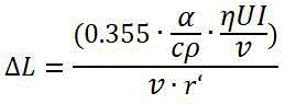
wherein, the amount of the welding deformation is indicated,
 representing the coefficient of thermal expansion of the material of the cylinder (10),
 represents the specific heat capacity of the material of the cylinder (10),
 indicating the density of the material of the cylinder (10),
 the efficiency of the cladding is shown,
 which is indicative of the welding voltage,
 the welding current is represented by the number of welding cycles,
 the speed of the welding is indicated by the indication,
 the diameter of the solder is shown.
5. The method for controlling the cylinder edge angle of the casing as defined in claim 2, wherein in the step 4, the relationship between the lifting amount and the welding deformation amount is as follows: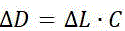 wherein
 the amount of jacking is shown as the amount of jacking,
 is a constant number of times, and is,
 the amount of welding deformation is indicated.
6. The method for controlling the cylinder angle of the soil covering tank as claimed in claim 2, wherein the specific process of step 5 is as follows: r type laser scanner (6) detect barrel (10) wrong limit volume before welding and feed back to controller (8), remote analog system (9) calculate welding deformation and feed back to controller (8), welding deformation and the real wrong limit volume of measuring that controller (8) obtained according to analog computation, obtain the deformation recommendation, again according to the relational expression between jacking volume and the welding deformation, the jacking volume that should apply on barrel (10) is obtained in the calculation, control hydraulic means (4) in view of the above jacking by oneself, guarantee that the edge angle after barrel (10) welding is accomplished satisfies the standard requirement.
7. The method for controlling the cylinder edge angle of the soil covering tank as claimed in claim 2, wherein the specific process of step 1 is as follows:
step 1.1: the remote simulation system (9) establishes a cylinder welding model based on finite element software according to the cylinder (10) and relevant welding parameters;
step 1.2: in finite element software, a welding seam module is associated with a cylinder welding model, each welding seam of the cylinder (10) is divided into the welding length in actual welding unit time, and the number of the divided welding seams is recorded;
step 1.3: guiding the cylinder welding model into a transient heat calculation module, setting materials of the cylinder welding model, confirming a global coordinate system, checking the contact condition between a welding seam module and the cylinder welding model, and confirming the contact relation;
step 1.4: processing the cylinder welding model by adopting a grid-divided sweeping mode;
step 1.5: establishing a plurality of surface sets according to the actual number of welding lines, and setting the ambient temperature, the transient heat source analysis step, the time of the analysis step and the convection coefficient;
step 1.6: inputting a Gaussian heat source formula into an APDL module to obtain a code of the Gaussian heat source, loading the Gaussian heat source on the surface of each welding seam, setting time parameters in each Gaussian heat source according to the time in the step 1.5, setting 'life and death units' in each welding seam according to the welding sequence to simulate the actual welding process, and calculating to obtain a temperature field of the welding seam of the cylinder (10);
step 1.7: loading the temperature field of the welding seam of the cylinder (10) into a static structure model, setting analysis steps, analysis time of each step and corresponding constraint conditions and loads, then setting the gravity action and the direction of the cylinder (10), setting the contact surface of the roller frame (11) and the cylinder (10) as a cylindrical support, completing the structural mechanics calculation of the cylinder (10) based on a welding heat source, and obtaining the welding deformation of the welding seam.
8. The method for controlling the cylinder edge angle of the casing as defined in claim 7, wherein in step 1.4, the structure size of the cylinder (10) is divided into a mesh size of 300mm, the structure size of the weld is divided into a mesh size of 10mm, and the surface size of the circular cross section at both ends of the cylinder (10) is divided into a mesh size of 10 mm.
9. The method for controlling the angle of the cylinder of the casing according to claim 7, wherein in step 1.5, the ambient temperature is set to 22 ℃ and the time interval of the analyzing step is 20 seconds.
Priority Applications (1)
| Application Number | Priority Date | Filing Date | Title |
|---|---|---|---|
| CN202211269769.4A CN115338552B (en) | 2022-10-18 | 2022-10-18 | System and method for controlling edge angle of cylinder of soil covering tank |
Applications Claiming Priority (1)
| Application Number | Priority Date | Filing Date | Title |
|---|---|---|---|
| CN202211269769.4A CN115338552B (en) | 2022-10-18 | 2022-10-18 | System and method for controlling edge angle of cylinder of soil covering tank |
Publications (2)
| Publication Number | Publication Date |
|---|---|
| CN115338552A CN115338552A (en) | 2022-11-15 |
| CN115338552B true CN115338552B (en) | 2023-01-24 |
Family
ID=83957146
Family Applications (1)
| Application Number | Title | Priority Date | Filing Date |
|---|---|---|---|
| CN202211269769.4A Active CN115338552B (en) | 2022-10-18 | 2022-10-18 | System and method for controlling edge angle of cylinder of soil covering tank |
Country Status (1)
| Country | Link |
|---|---|
| CN (1) | CN115338552B (en) |
Citations (6)
| Publication number | Priority date | Publication date | Assignee | Title |
|---|---|---|---|---|
| JP2008046029A (en) * | 2006-08-18 | 2008-02-28 | Genshiryoku Anzen Syst Kenkyusho:Kk | Optical vibration distortion measuring device |
| CN210242748U (en) * | 2019-04-28 | 2020-04-03 | 南京三方化工设备监理有限公司 | Barrel inner side circumferential edge angle detection device based on laser scanning |
| CN112050753A (en) * | 2020-09-10 | 2020-12-08 | 广东省特种设备检测研究院珠海检测院 | Method and device for measuring edge angle of longitudinal weld of pressure vessel |
| CN112149330A (en) * | 2020-09-24 | 2020-12-29 | 河海大学常州校区 | Method for predicting welding residual stress of oil seal platform of wind power tower and optimizing welding process |
| CN212806936U (en) * | 2019-12-10 | 2021-03-26 | 刘振英 | Welding bead detection device |
| CN113639659A (en) * | 2021-08-10 | 2021-11-12 | 广东省特种设备检测研究院惠州检测院 | Comprehensive detector and measuring method for measuring geometric dimension of special pressure-bearing equipment |
-
2022
- 2022-10-18 CN CN202211269769.4A patent/CN115338552B/en active Active
Patent Citations (6)
| Publication number | Priority date | Publication date | Assignee | Title |
|---|---|---|---|---|
| JP2008046029A (en) * | 2006-08-18 | 2008-02-28 | Genshiryoku Anzen Syst Kenkyusho:Kk | Optical vibration distortion measuring device |
| CN210242748U (en) * | 2019-04-28 | 2020-04-03 | 南京三方化工设备监理有限公司 | Barrel inner side circumferential edge angle detection device based on laser scanning |
| CN212806936U (en) * | 2019-12-10 | 2021-03-26 | 刘振英 | Welding bead detection device |
| CN112050753A (en) * | 2020-09-10 | 2020-12-08 | 广东省特种设备检测研究院珠海检测院 | Method and device for measuring edge angle of longitudinal weld of pressure vessel |
| CN112149330A (en) * | 2020-09-24 | 2020-12-29 | 河海大学常州校区 | Method for predicting welding residual stress of oil seal platform of wind power tower and optimizing welding process |
| CN113639659A (en) * | 2021-08-10 | 2021-11-12 | 广东省特种设备检测研究院惠州检测院 | Comprehensive detector and measuring method for measuring geometric dimension of special pressure-bearing equipment |
Non-Patent Citations (1)
| Title |
|---|
| 基于线激光扫描工业角焊缝外观的判识;范力予等;《焊接技术》;20160228;第45卷(第02期);第72-75页 * |
Also Published As
| Publication number | Publication date |
|---|---|
| CN115338552A (en) | 2022-11-15 |
Similar Documents
| Publication | Publication Date | Title |
|---|---|---|
| US9427827B2 (en) | Method for manufacturing a door frame, welding arrangement and structure of a door frame | |
| CN110258803A (en) | A kind of dome steel structure construction method of installation based on BIM technology | |
| CN105019665A (en) | Method for mounting long-span structure beam based on total station | |
| CN105006261B (en) | Nuclear fuel assembly video detecting method and detection means | |
| CN112761199A (en) | Static pressure anchor rod pile and broken pile underpinning supporting device for high-rise deviation correction and monitoring method thereof | |
| CN107988908A (en) | The total assembling method of tubular arch | |
| CN113843540A (en) | Rail welding of pipes and pipe sections | |
| CN120250640A (en) | A monitoring control system for static pile driver construction and its implementation method | |
| CN110242333A (en) | A kind of tunnel grillage moulding bed and its processing method | |
| CN116988607A (en) | A construction method for curved roof of W-shaped steel structure | |
| CN112404883B (en) | Real-time accurate liquid micro-forging additive remanufacturing method and device | |
| CN115338552A (en) | System and method for controlling edge angle of cylinder of soil covering tank | |
| CN117951799A (en) | Long-term treatment method for lateral convergence deformation of subway shield tunnel | |
| CN117145530A (en) | A method for precise positioning and installation of tunnel arch frames | |
| CN116791485A (en) | Precision control method for pre-assembling steel box girder segments | |
| CN120562079B (en) | Wind generating set tower tube welding seam optimization method based on fluid dynamics | |
| CN121279042A (en) | Method for positioning penetration construction of oversized steel column | |
| CN117182461B (en) | A method for manufacturing and construction control of a continuous steel box girder with a small curvature and high pier | |
| CN119178465A (en) | Calibration method for gear shaft after welding | |
| CN117798537B (en) | A welding control system for manufacturing steel structure skeleton of building curtain wall | |
| CN209614622U (en) | Movable rib cage erection welding stage apparatus | |
| CN110144828A (en) | The linear control method of the location structure of steel box girder assembling, support construction and bridge | |
| CN118417660A (en) | A fillet weld penetration control method based on machine learning and laser tracking | |
| CN117146775A (en) | A verticality detection system and detection method for lowering the steel box with rigid joints to the ground and to the wall | |
| KR20230155268A (en) | System and Method for installing chain compressor |
Legal Events
| Date | Code | Title | Description |
|---|---|---|---|
| PB01 | Publication | ||
| PB01 | Publication | ||
| SE01 | Entry into force of request for substantive examination | ||
| SE01 | Entry into force of request for substantive examination | ||
| GR01 | Patent grant | ||
| GR01 | Patent grant |