CN115251726A - Air frying pan - Google Patents
Air frying pan Download PDFInfo
- Publication number
- CN115251726A CN115251726A CN202210809576.7A CN202210809576A CN115251726A CN 115251726 A CN115251726 A CN 115251726A CN 202210809576 A CN202210809576 A CN 202210809576A CN 115251726 A CN115251726 A CN 115251726A
- Authority
- CN
- China
- Prior art keywords
- air
- cavity
- cooking
- hot air
- wall
- Prior art date
- Legal status (The legal status is an assumption and is not a legal conclusion. Google has not performed a legal analysis and makes no representation as to the accuracy of the status listed.)
- Pending
Links
Images


Classifications
-
- A—HUMAN NECESSITIES
- A47—FURNITURE; DOMESTIC ARTICLES OR APPLIANCES; COFFEE MILLS; SPICE MILLS; SUCTION CLEANERS IN GENERAL
- A47J—KITCHEN EQUIPMENT; COFFEE MILLS; SPICE MILLS; APPARATUS FOR MAKING BEVERAGES
- A47J37/00—Baking; Roasting; Grilling; Frying
- A47J37/06—Roasters; Grills; Sandwich grills
- A47J37/0623—Small-size cooking ovens, i.e. defining an at least partially closed cooking cavity
- A47J37/0629—Small-size cooking ovens, i.e. defining an at least partially closed cooking cavity with electric heating elements
- A47J37/0641—Small-size cooking ovens, i.e. defining an at least partially closed cooking cavity with electric heating elements with forced air circulation, e.g. air fryers
Landscapes
- Engineering & Computer Science (AREA)
- Food Science & Technology (AREA)
- Frying-Pans Or Fryers (AREA)
Abstract
The invention discloses an air fryer, which comprises a main body structure, a top hot air structure and a bottom hot air structure, wherein the main body structure is provided with a cooking cavity, a top air passing cavity, a bottom air passing cavity, a top air inlet, a bottom air inlet and an air outlet, the top hot air structure is positioned in the cooking cavity and/or the top air passing cavity and used for forming hot air in the top air passing cavity and transmitting the hot air to the cooking cavity, and the bottom hot air structure is positioned in the bottom air passing cavity and used for forming hot air in the bottom air passing cavity and transmitting the hot air to the top air passing cavity. The air fryer can improve cooking efficiency, simplify operation and fry and roast food with better mouthfeel.
Description
Technical Field
The invention relates to the technical field of household appliances, in particular to an air fryer.
Background
The existing cooking appliances which can utilize hot air circulation to fry and bake food in air are popular among people.
The air fryer, as a typical appliance in the cooking appliance, is widely used due to the advantages of wide cooking range, convenient use, environmental protection, short cooking time and the like. The hot air structure is used as a core component of the air fryer and plays a crucial role in the frying and baking effect of food and the like.
The existing air fryer is generally only provided with a set of hot air structure at the top, the hot air structure mainly comprises a fan and a heating pipe, after the air fryer is started, the heating pipe starts to heat, meanwhile, the fan adsorbs surrounding air and passes through the heating pipe to realize hot air circulation, and most of the air adsorbed by the fan is cold air within a period of time after the air fryer is started, so that the air fryer is influenced by the cold air, the heating pipe reaches a specified temperature for a long time, the rising time of the whole temperature of the hot air circulation is influenced, and the cooking efficiency of the air fryer is poor; on the other hand, based on the design of a single hot air structure at the top, the hot air circulation is insufficient, the temperature in the space of the frying barrel is uneven, the phenomenon that the local part of the food is fried and crisp and other parts are still uncooked or in a water boiling state is easy to occur when the food is fried and baked, so that the fried taste of the food is not good, the process of turning over the food is increased when the food is fried and baked, the operation is complicated, the baking time can be prolonged, and the cooking efficiency of the air-frying pot is also influenced.
Disclosure of Invention
The invention provides an air fryer, aiming at solving the technical problems of low cooking efficiency, poor taste and complex operation of the existing air fryer.
According to an embodiment of the present invention, the air fryer includes:
the cooking device comprises a main body structure, a cooking cavity, a top air passing cavity, a bottom air passing cavity, a top air inlet and a bottom air inlet, wherein the top air passing cavity is communicated with the cooking cavity;
a top air heating structure located in the cooking cavity and/or the top air passing cavity and used for forming hot air in the top air passing cavity and transmitting the hot air to the cooking cavity;
and the bottom hot air structure is positioned in the bottom air passing cavity and used for forming hot air in the bottom air passing cavity and transmitting the hot air to the top air passing cavity.
In one embodiment, the main structure comprises a framework structure with a drawing opening and a cooking pot body which can be loaded into the framework structure from the drawing opening, the bottom air passing cavity is formed by a space enclosed by the cooking pot body and the framework structure, and air in the bottom air passing cavity can enter the top air passing cavity through the cooking pot body.
In one embodiment, the skeleton structure comprises an outer frame body and a frame body, wherein the frame body is arranged in the outer frame body to divide the outer frame body into the cooking cavity and the top air passing cavity which are communicated with each other.
In one embodiment, the outer periphery of the rack body is provided with a convection through hole, the cooking pot body is provided with an air flow channel communicated with the convection through hole, and the bottom air passing cavity is communicated with the top air passing cavity through the convection through hole and the air flow channel.
In one embodiment, the cooking pot body comprises a pot body and an insulating barrel wall connected to the pot body, and the air flow channel is formed in the insulating barrel wall.
In one embodiment, a cavity is formed inside the heat insulation barrel wall, a hot air inlet is formed in one side of the heat insulation barrel wall facing the cooking cavity, a communication port is formed in the top of the heat insulation barrel wall, and the air flow channel comprises a hot air channel formed by the hot air inlet, the cavity and the communication port.
In one embodiment, the heat insulation barrel wall is further provided with a cold air inlet, and the air flow channel further comprises a cold air channel formed by the cold air inlet, the cavity and the communication port.
In one embodiment, the hot air inlet is arranged in the middle of the bottom of the heat insulation barrel wall, and the cold air inlet is arranged on two sides of the bottom of the heat insulation barrel wall.
In one embodiment, the heat insulation barrel wall comprises an inner wall and an outer wall which are fastened, the inner wall and the outer wall form the cavity, the hot air inlet and the cold air inlet are formed in the inner wall, a wind shield located in the cavity is further arranged on the inner wall and/or the outer wall, and the wind shield is used for separating the cold air channel from the hot air channel.
In one embodiment, heat transfer through holes are formed on other sides of the outer periphery of the frame body, so that heat in the bottom air passing cavity is transferred outwards through the pot body, the heat insulation surrounding body and the frame body.
In one embodiment, the outer frame comprises a base assembly including a bottom cover, a bottom heat insulation plate disposed on the bottom cover, the bottom heat insulation plate covering the bottom cover to form a buffer chamber, and external air can enter the bottom air passing chamber through the buffer chamber.
The embodiment of the invention has the following beneficial effects:
according to the air fryer in the above embodiment, based on the design of top hot air structure and bottom hot air structure, when starting the air fryer, bottom hot air structure can carry a certain amount of hot air to top air passing cavity, this hot air can be utilized by top hot air structure, the air source that top hot air structure utilized this moment not only includes cold air, also includes hot air, make at the top income wind gap, top air passing cavity, the hot air circulation's that forms between culinary art chamber and the air exit whole temperature can rise fast, the dual function of top hot air structure and bottom hot air structure simultaneously, can aggravate the violent degree of above-mentioned hot air circulation, hot air circulation can be more abundant, make the temperature in the culinary art intracavity more even, not only be favorable to frying out the food that the taste is better, do not worry simultaneously not carrying out the emergence of the inhomogeneous phenomenon of being heated because of not carrying out the operation of turning over the face to food in the in-process of frying food, can simplify the operation, hot air circulation's whole temperature can rise fast and the violent degree of hot air circulation is combined with the degree can both can promote the culinary art efficiency of air fryer.
Drawings
In order to more clearly illustrate the embodiments of the present invention or the technical solutions in the prior art, the drawings used in the embodiments or the prior art descriptions will be briefly described below, it is obvious that the drawings in the following description are only some embodiments of the present invention, and other drawings can be obtained by those skilled in the art without creative efforts.
Wherein:
FIG. 1 illustrates an external profile view of an air fryer pot provided in accordance with an embodiment of the present invention;
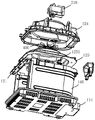
FIG. 2 illustrates an exploded view of an air fryer provided in accordance with an embodiment of the present invention;
FIG. 3 illustrates another exploded view of an air fryer in accordance with an embodiment of the present invention;
FIG. 4 illustrates a cross-sectional view of an air fryer provided in accordance with an embodiment of the present invention;
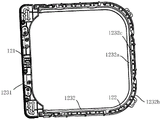
fig. 5 is a schematic view illustrating a structure of a connection ring according to an embodiment of the present invention;
FIG. 6 is a schematic structural diagram of a cooking pot provided in an embodiment of the invention;
FIG. 7 shows an exploded view of a cooking pot provided in accordance with an embodiment of the present invention;
fig. 8 shows a schematic structural diagram of an inner wall of a cooking pot body according to an embodiment of the invention.
Description of the main element symbols:
100-a body structure; 101-a cooking cavity; 102-a top air passing cavity; 103-bottom air passing cavity; 104-top air inlet; 105-bottom air inlet; 106-air outlet; 110-an outer frame; 120-a frame body; 130-cooking pan body; 140-a thermally insulating enclosure; 111-a pull port; 112-a top cover; 113-a fuselage; 114-a base assembly; 121-convection pass-through; 122-heat transfer through holes; 123-connecting ring; 124-a housing frame; 125-a heat shield; 131-a pan body; 132-a handle; 133-insulating tub walls; 1141-bottom cover; 1142-bottom insulation board; 1143-an interior base plate; 1231-convection section; 1232-a bicyclic moiety; 1251-hot air outlet; 1331-a hot air inlet; 1332-cold air inlet; 1333-a communication port; 1334-an inner wall; 1335-outer wall; 1336-wind deflector; 1232 a-inner loop; 1232 b-outer loop; 1232 c-tie bar;
200-top hot air structure; 210-a motor; 220-a hot air fan; 230-top heating tube;
300-bottom hot air structure;
400-cooling fan.
Detailed Description
To facilitate an understanding of the invention, the invention will now be described more fully with reference to the accompanying drawings. Preferred embodiments of the present invention are shown in the drawings. The invention may, however, be embodied in many different forms and should not be construed as limited to the embodiments set forth herein. Rather, these embodiments are provided so that this disclosure will be thorough and complete.
It will be understood that when an element is referred to as being "secured to" another element, it can be directly on the other element or intervening elements may also be present. When an element is referred to as being "connected" to another element, it can be directly connected to the other element or intervening elements may also be present. The terms "vertical," "horizontal," "left," "right," and the like as used herein are for illustrative purposes only.
Unless defined otherwise, all technical and scientific terms used herein have the same meaning as commonly understood by one of ordinary skill in the art to which this invention belongs. The terminology used in the description of the invention herein is for the purpose of describing particular embodiments only and is not intended to be limiting of the invention. As used herein, the term "and/or" includes any and all combinations of one or more of the associated listed items.
The embodiment of the invention provides an air fryer, which adopts a double hot air structure, can quickly heat the air fryer in a short time through the combined action of the double hot air structure, and can make the internal temperature of the air fryer more balanced.
In an embodiment of the present invention, referring to fig. 1-4, the air fryer includes a main body structure 100, a top hot air structure 200 and a bottom hot air structure 300.
The main body structure 100 mainly utilizes a solid structure to form each cavity, and the corresponding cavity is communicated with the outside or between the cavities through an opening, a window, an opening and the like at an adaptive position of the corresponding solid structure.
The main body structure 100 is formed with a cooking cavity 101, a top air passing cavity 102 communicating with the cooking cavity 101, a bottom air passing cavity 103 communicating with the top air passing cavity 102, a top air inlet 104 communicating with the top air passing cavity 102, and a bottom air inlet 105 communicating with the bottom air passing cavity 103.
It can be understood that the air fryer mainly uses hot air circulation to fry and bake the food, where the top air inlet 104 and the top air passing cavity 102 can be used as one place for hot air circulation, and the bottom air inlet 105 and the bottom air passing cavity 103 can be used as the other place for hot air circulation, and hot air generated by the two places can enter the cooking cavity 101 to fry and bake the food in the cooking cavity 101, and the entering manners are different, the former directly enters and the latter indirectly enters.
In order to ensure the balance of the hot air circulation, the main body structure 100 is further formed with an air outlet 106, and the air outlet 106 communicates at least with the cooking chamber 101 in the cooking chamber 101 and the top air passing chamber 102.
This air exit 106 is arranged in time discharging the air and crouches unnecessary heat in the pot, makes the heat that the air crouches in the pot keep at a certain balanced state, and air exit 106 can communicate culinary art chamber 101 or top air passing chamber 102, and air exit 106 communicates culinary art chamber 101 can take away the steam that the culinary art intracavity food cooked the in-process and produced, thereby air exit 106 communicates top air passing chamber 102 can increase the intake of top air passing chamber 102 and realize the holistic heat dissipation of frying the pot organism.
The top air heater structure 200 is located in the cooking chamber 101 and/or the top air passing chamber 102 to form hot air in the top air passing chamber 102 and transfer the hot air to the cooking chamber 101.
The top air structure 200 can utilize the air entering the top air passing chamber 102 to form a hot air circulation, wherein a part of the air comes from the top air inlet 104, and another part of the air comes from the bottom air passing chamber 103 communicated with the top air passing chamber 102.
The bottom air heater 300 is located in the bottom air passing chamber 103 and is used for forming hot air in the bottom air passing chamber 103 and transmitting the hot air to the top air passing chamber 102.
The bottom hot air structure 300 may adopt some components or structures capable of generating heat, such as heating tubes, and when the heating tubes are adopted, the heating tubes are preferably bent and arranged in a roundabout manner to increase the contact area with air.
The air utilized by the bottom hot air structure 300 comes from the bottom air inlet 105 communicated with the bottom air passing cavity 103, and the air entering the bottom air passing cavity 103 is heated by the bottom hot air structure 300 and then is conveyed to the top air passing cavity 102 from bottom to top.
It should be added that the air fryer generally relies on the motor therein to drive the fan blades to rotate so as to create a negative pressure inside the air fryer, and based on this negative pressure, the outside air spontaneously enters the air fryer through the top air inlet 104 and the bottom air inlet 105, and then the air is driven by the fan blades and the physical structure of the air fryer to create a hot air circulation. When the motor is started, a climbing phenomenon generally occurs, in other words, in a period of time when the air fryer is just started, the negative pressure inside the air fryer is low, and at this time, for the bottom air passing cavity 103, only the hot air inside the bottom air passing cavity 103 flows to the top air passing cavity 102 according to the air convection principle. After the motor works stably, the negative pressure in the air fryer is increased, and at the moment, both hot air and cold air in the bottom air passing cavity 103 enter the top air passing cavity 102.
In the embodiment of the present invention, based on the design of the top hot air structure 200 and the bottom hot air structure 300, when the air fryer is started, the bottom hot air structure 300 can deliver a certain amount of hot air to the top air passing cavity 102, and the hot air can be utilized by the top hot air structure 200, at this time, an air source utilized by the top hot air structure 200 includes not only cold air but also hot air, so that the overall temperature of a hot air circulation formed among the top air inlet 104, the top air passing cavity 102, the cooking cavity 101, and the air outlet 106 can be rapidly raised, and meanwhile, due to the dual functions of the top hot air structure 200 and the bottom hot air structure 300, the intensity of the hot air circulation can be enhanced, the hot air circulation can be more sufficient, so that the temperature in the cooking cavity 101 is more uniform, which is not only beneficial to frying and roasting food with better taste, but also the occurrence of a phenomenon that the food is not unevenly heated due to the fact that the food is not subjected to a turn-over operation during the frying of the food can be avoided, the operation can be simplified, and the overall temperature of the hot air circulation can be rapidly raised in combination with the increase of the intensity of the cooking efficiency of the air frying.
The above only explains the promotion effect of the bottom hot air structure 300 on the whole hot air circulation from the aspect of air convection, but it can be understood that heat transfer can also be realized in a heat conduction manner, at this time, by reasonably selecting the solid part of the main body structure 100 and making the corresponding component parts from materials easy to conduct heat, the heat in the bottom air passing cavity 103 can also enter the top air passing cavity 102 or the cooking cavity 101 in a heat conduction manner, and the part of heat can also promote the temperature homogenization in the cooking cavity 101, which is beneficial to improving the cooking efficiency and promoting the frying and roasting effects on food.
In one embodiment, referring to fig. 1 to 4, the main structure 100 includes a framework structure having a drawing opening 111 and a cooking pot 130 capable of being loaded into the framework structure from the drawing opening 111, the bottom air passing cavity 103 is formed by a space enclosed by the cooking pot 130 and the framework structure, and air in the bottom air passing cavity 103 can enter the top air passing cavity through the cooking pot 130.
It is to be understood herein that the skeletal structure that is part of the body structure 100 other than the cooking pot 130 serves as a structural support and mounting carrier for the air fryer, enabling the air fryer to maintain a desired strength and provide support for the other components of the air fryer.
It is to be understood that the specific type and structure of the skeleton structure are not limited, and may be set according to the requirement, and the material and the like may also be selected according to the requirement.
In one embodiment, referring to fig. 1 to 4, the frame structure includes an outer frame 110 and a frame 120, wherein the frame 120 is disposed in the outer frame 110 to divide the outer frame 110 into a cooking cavity 101 and a top air-passing cavity 102 that are communicated with each other.
This skeleton texture still includes thermal-insulated enclosure 140, this thermal-insulated enclosure 140 connects between the bottom of outside framework 110 and support body 120, the culinary art pot body 130 can pack into culinary art chamber 101 and leave the clearance between the bottom of outside framework 110, thermal-insulated enclosure 140 can surround the periphery at the culinary art pot body 130, thermal-insulated enclosure 140, the culinary art pot body 130, support body 120 and outside framework 110 enclose and close and form bottom air passing cavity 103, the outer periphery of support body 120 is provided with convection current through-hole 121, culinary art pot body 130 is formed with the air current passageway with convection current through-hole 121 intercommunication, bottom air passing cavity 103 communicates through clearance, convection current through-hole 121 and air current passageway top air passing cavity 102.
After the cooking pan body 130 is loaded into the cooking cavity 101 and the air fryer is started, heated hot air in the bottom air passing cavity 103 can enter the top air passing cavity 102 through the air flow channel and the convection through hole 121, part of the hot air can be utilized by the top hot air structure 200, when the air fryer reaches a certain balance state, redundant hot air can be discharged through the air outlet 106, the part of the process is a convection effect, and by the convection effect, the purposes of improving the cooking efficiency, simplifying the operation and improving the food taste can be realized, and the phenomenon that the surface temperature of the air fryer is too high due to the accumulation of heat in the bottom air passing cavity 103 can be avoided; as described above, heat can be transferred by heat conduction effect, heat generated by hot air in the bottom air passing cavity 103 can be transferred to the inside of the cooking pot 130, the heat can also promote temperature balance inside the cooking pot 130, and meanwhile, the heat can also be transferred to the frame body 120 through the surfaces of the cooking pot 130 and the heat insulation surrounding body 140, and then transferred to the air outlet 106 through the frame body 120, so that the purpose of frying the air by discharging redundant heat can be achieved, and the important function of reducing the surface temperature of the air frying pot can be achieved.
In this embodiment, the external frame 110, the frame 120, the cooking pan 130 and the heat insulation enclosure 140 enclose the cavities required to form the main structure 100, and then, on the basis of realizing the hot air circulation with the above functions by means of the convection effect and the heat conduction effect, the excess heat in the bottom air passing cavity 103 can be dissipated by means of the convection effect and the heat conduction effect, so as to avoid the surface temperature of the air fryer to be too high.
In this embodiment, the external frame 110, the frame 120, the cooking pan 130 and the heat insulation enclosure 140 enclose the cavities required to form the main structure 100, and the structures can be connected by using a connecting member such as a screw, for example, the frame 120 is connected to a substantially central position of the external frame 110 to divide the internal space of the external frame 110 into the top air passing cavity 102 and the cooking cavity 101 arranged up and down; for another example, the heat insulation enclosure 140 may be connected between the bottom of the outer frame 110 and the frame 120 by a connector such as a screw, and at this time, the heat insulation enclosure 140 may independently isolate an actual cooking area in the cooking cavity 101, which conforms to the shape of the cooking pot 130, and the heated air circulates in the actual cooking area, and at this time, after the cooking pot 130 is loaded into the actual cooking area, the heated air circulates to fry and bake the food in the cooking pot 130. The main structure 100 is formed by combining the outer frame 110, the frame 120, the cooking pot 130 and the heat insulation surrounding body 140, and all the components are reliably connected, so that required cavities are easily constructed.
In addition, in order to facilitate the taking and placing of the cooking pan body 130, a drawing opening 111 is opened at a position of the outer frame 110 corresponding to the actual cooking area, the cooking pan body 130 can be installed into the actual cooking area or taken out from the actual cooking area through the drawing opening 111, and after the cooking pan body 130 is installed in place, the three can be hermetically connected by the structural design of the joints of the cooking pan body 130, the outer frame 110 and the heat insulation enclosure 140, for example, an abutting joint or a nesting joint design can be adopted, so as to prevent hot air from leaking from the gap between the cooking pan body 130 and the outer frame 110 to affect the cooking efficiency.
The outer frame 110 serves as the outer contour structure of the air fryer and protects other structural components of the air fryer. In addition, in order to prevent the surface temperature of the air fryer from being too high during operation, the outer frame 110 is preferably made of a material having a heat insulating function.
In one embodiment, referring to fig. 1 to 4, the outer frame 110 includes a top cover 112, a body 113, and a base assembly 114, wherein the top air inlet 104 is formed on the top cover 112, the bottom air inlet 105 is formed on the base assembly 114, and the air outlet 106 is formed on the body 113.
The outer frame 110 is designed to be a three-part structure, which can be easily assembled and produced, for example, the relevant structures can be first installed on the base assembly 114, for example, the heat-insulating enclosure 140 is assembled on the base assembly 114 by screws, then the frame 120 is connected to the heat-insulating enclosure 140, then the frame 113 is covered, and finally the top cover 112 is assembled to realize the integral assembly of the air fryer, and the top cover 112 can be provided with an operation panel, an indicator light, and other structures; on the other hand, the outer frame 110 with a separate design is also beneficial to maintaining the relevant structures in different areas, for example, when a control panel on the top cover 112 fails, the control panel can be detached or the top cover 112 can be detached as a whole for maintenance and replacement.
In addition, corresponding to the above description, the "bottom of the outer frame 110" is the base assembly 114, the thermal insulation enclosure 140 can be connected to the base assembly 114, a bottom air inlet 105 is formed on the base assembly 114, and the outside air can enter the bottom air passing chamber 103 through the base assembly 114.
In one embodiment, referring to fig. 1 to 4, the base assembly 114 includes a bottom cover 1141, a bottom heat insulation plate 1142 disposed on the bottom cover 1141, and an inner bottom plate 1143 disposed on the bottom heat insulation plate 1142, the bottom heat insulation plate 1142 covers the bottom cover 1141 to form a buffer cavity, the external air can enter the bottom air passing cavity 103 through the buffer cavity, the bottom air heating mechanism 300 can be mounted on the inner bottom plate 1143, and the bottom air inlet 105 can be formed on the bottom cover 1141, the bottom heat insulation plate 1142 and the inner bottom plate 1143.
Specifically, the bottom heat insulating plate 1142 is made of an insulating material to provide heat insulation, and the bottom heat insulating plate 1142 may be separately assembled to the bottom cover 1141, or may be sequentially assembled to the bottom cover 1141 by a connector such as a screw through a screw hole on the inner wall of the body 113, the bottom heat insulating plate 1142 and a screw hole on the bottom cover 1141. Similarly, the inner bottom plate 1143 may be assembled directly to the bottom insulation plate 1142, or assembled to the bottom insulation plate 1142 by screws or other connectors passing through the insulation enclosure 140, the inner bottom plate 1143 and the bottom insulation plate 1142 in sequence, although there are many alternatives for the assembly of the bottom cover 1141, the bottom insulation plate 1142 and the inner bottom plate 1143, which are not listed herein.
It should be noted here that by the design of the buffer cavity formed by the bottom heat insulation plate 1142 and the inner bottom plate 1143, the outside air is more easily introduced into the bottom air passing cavity 103, and the air convection effect is more easily activated.
As described above, the bottom air passing chamber 103 is connected to the top air passing chamber 102 via the air flow passage on the cooking pot 130 and the convection through hole 121 on the frame 120, which will be described in detail below.
Referring to fig. 3 to 7, the convection through hole 121 is formed at one side of the outer circumference of the frame 120, the cooking pot 130 includes a pot body 131, a handle 132, and an insulating tub wall 133 connected between the pot body 131 and the handle 132, and an air flow passage is formed in the insulating tub wall 133 and communicates with the convection through hole 121 after the cooking pot 130 is pushed into the cooking cavity 101.
When the cooking pot 130 is used, the handle 132 is usually held by hand to push the cooking pot into the cooking cavity 101, and at this time, the outer wall surface of the pot body 131, the inner surface of the heat-insulating enclosure 140, the lower surface of the frame 120 and the bottom surface of the outer frame 110 enclose the bottom air-passing cavity 103, and this space is generally designed to be in a sealed state except for necessary openings (such as the aforementioned bottom air inlet 105), so that it is desirable to achieve the purpose that the hot air in the bottom air-passing cavity 103 flows into the top air-passing cavity 102, and it is preferable to arrange the heat-insulating barrel wall 133 to have an air flow channel, and at the same time, after the cooking pot 130 is completely pushed into the cooking cavity 101, the air flow channel on the heat-insulating barrel wall 133 can be communicated with the convection through hole 121 on the frame 120, thereby achieving the above purpose.
Of course, in other embodiments, the bottom air passing chamber 103 surrounded by the outer wall surface of the pan body 131, the inner surface of the heat insulation surrounding body 140, the lower surface of the frame body 120, and the bottom surface of the outer frame 110 may not be sealed, for example, the other sides of the outer periphery of the frame body 120 are also provided with convection through holes 121 or a gap is left between the top of the pan body 131 and the frame body 120, and at this time, the hot air in the bottom air passing chamber 103 can also flow to the top air passing chamber 102. However, in consideration of the stability of the operation, the bottom air passing chamber 103 is generally designed to be in a sealed state, which is mainly described as an example below.
In a specific embodiment, referring to fig. 6 and 7, a cavity is formed inside the heat insulation barrel wall 133, a hot air inlet 1331 is formed at a position of one side of the heat insulation barrel wall 133 facing the cooking cavity 101, the hot air inlet 1331 may be located at the middle of the bottom of the side of the heat insulation barrel wall 133 facing the cooking cavity 101, a communication port 1333 is formed at the top of the heat insulation barrel wall 133, and the air flow channel includes a hot air channel formed by the hot air inlet 1331, the cavity and the communication port 1333;
the heat insulation barrel wall 133 is further provided with a cold air inlet 1332 communicated with the outside air, the cold air inlet 1332 may be provided at any position of the heat insulation barrel wall 133 communicated with the outside air, specifically, at two sides of the bottom of the heat insulation barrel wall 133, so that the position of the cold air inlet 1332 may be staggered with the position of the hot air inlet 1331, or may not be on the same plane with the position of the hot air inlet 1331, and the air flow channel further includes a cold air channel formed by the cold air inlet 1332, the cavity and the communication port 1333.
In combination with the above, during the period of starting the air fryer, the air inside the bottom air passing chamber 103 is heated to form hot air, air convection is formed inside the bottom air passing chamber 103, the negative pressure inside the air fryer is low, for example, 10 to 25Kpa, only the hot air enters the top air passing chamber 102 through the hot air channel, and after the operation is stable, when the negative pressure rises to be greater than 25Kpa, the hot air and the cold air in the bottom air passing chamber 103 respectively enter the top air passing chamber 102 through the hot air channel and the cold air channel.
In a more specific embodiment, referring to fig. 6 to 8 in combination, the heat insulation barrel wall 133 includes an inner wall 1334 and an outer wall 1335 that are fastened to each other, the inner wall 1334 and the outer wall 1335 form a cavity, the hot air inlet 1331 and the cold air inlet 1332 are formed on the inner wall 1334, and a wind shield 1336 is further disposed on the inner wall 1334 and/or the outer wall 1335 and located in the cavity to separate the cold air passage from the hot air passage.
It should be noted here that, when the air fryer is started, the temperature inside the air fryer needs to be raised to a specified level at a relatively high speed, and during a period of time when the air fryer is just started, only the hot air in the bottom air passing cavity 103 can enter the top air passing cavity 102, at this time, by means of the structural design of the air baffle 1336, the hot air can be relatively concentrated in the hot air channel, the hot air can be prevented from being diffused to the periphery, and therefore, the speed of the hot air entering the top air passing cavity 102 can be raised, which has an important meaning for rapidly raising the overall temperature of the auxiliary hot air circulation.
In some embodiments, the rack 120 may be formed with heat transfer through holes 122 at other sides of the outer circumference of the rack 120, in addition to the convection through holes 121 at one side of the outer circumference thereof, so that the heat in the bottom air passing chamber 103 is transferred outward via the pot body 131, the heat insulation enclosure 140, and the rack 120.
The excessive heat in the bottom air passing cavity 103 can be quickly dissipated by the part of heat transferred outwards, the surface temperature of the air fryer can be effectively reduced, and the part of heat can be dissipated through the air outlet 106.
Preferably, the rack body 120 is provided with both the convection through-hole 121 and the heat transfer through-hole 122, and based on this, the rack body 120 may be designed in the following manner.
Referring to fig. 4 and 5, the frame body 120 includes a connection ring 123 and a housing frame 124 disposed on the connection ring 123, the housing frame 124 covers the connection ring 123, the top hot air structure 200 is disposed on the housing frame 124, the connection ring 123 includes a convection portion 1231 and a dual-ring structure portion 1232, the convection through hole 121 is formed on the convection portion 1231, the dual-ring structure portion 1232 includes an inner ring 1232a, an outer ring 1232b and a plurality of connection ribs 1232c connected between the inner ring 1232a and the outer ring 1232b, and the plurality of connection ribs 1232c divide a space between the inner ring 1232a and the outer ring 1232b into a plurality of heat transfer through holes 122.
The connecting ring 123 adopts a double-ring structure design, so that the structural strength is increased, and the problem of breakage of the air fryer caused by careless falling can be effectively prevented.
In a specific embodiment, referring to fig. 2 to 4, the frame 120 further includes a heat insulation cover 125 disposed below the housing frame 124, the top hot air structure 200 includes a motor 210, a hot air fan 220 and a top heating pipe 230, the motor 210 is disposed on the housing frame 124, the hot air fan 220 is connected to an output shaft of the motor 210, the hot air fan 220 and the top heating pipe 230 are disposed below the heat insulation cover 125, and the heat insulation cover 125 is provided with a hot air outlet 1251 communicated with the air outlet 106.
This setting of heat exchanger 125 can make the hot-air in the culinary art chamber 101 can frequently use, can prevent effectively that the heat in the culinary art chamber 101 from giving off fast, and after reaching balanced state, unnecessary hot-air can be discharged to the external world via hot air outlet 1251 and air exit 106.
In a more specific embodiment, referring to fig. 3 and 4, the air fryer further includes a cool air fan 400, wherein the cool air fan 400 is disposed between the housing frame 124 and the heat shield 125 for generating a cool air flow on a path passing through the motor 210 to cool the motor 210.
To facilitate a clearer understanding of the operational flow and advantages of the fryer provided by the embodiments herein, reference will now be made to the preferred embodiments listed above, and in the following description, reference will be made primarily to the flow of hot air and the direction of heat transfer.
Without referring to fig. 4, when the air fryer is just started, the top hot air structure 200 starts to work, negative pressure starts to be generated inside the air fryer, the negative pressure is at a low level, at the same time, external air enters the top air passing cavity 102 and the bottom air passing cavity 103 through the top air inlet 104 and the bottom air inlet 105 respectively, and hot air starts to be generated respectively, the air entering from the top air inlet 104 flows along the convection path S1, and at the same time, the hot air in the bottom air passing cavity 103 enters the top air passing cavity 102 along the convection path S2 to be utilized, at the same time, the hot air is mixed into the air utilized by the top hot air structure 200, so that the overall temperature of the hot air circulation can rapidly rise, after a while, the air fryer reaches a balanced state, the cold air in the bottom air passing cavity 103 also enters the top air passing cavity 102, at the same time, the hot air in the cooking cavity 101 flows along the convection path S3 (other convection paths) to and back, so that the hot air is fully diffused into the fryer, and the excess hot air is discharged from the air outlet 106, the air outlet S2, the cooking cavity S2 along the convection path S4, the cooking cavity S3, the cooking efficiency is further reduced, and the hot air circulation in the top air cavity 103 is controlled to reduce the cooking efficiency, and the cooking efficiency of the frying pan is finally, and the cooking surface, and the frying pan is increased, and the cooking efficiency of the food frying pan is increased, and the cooking pan is reduced, and the cooking efficiency is increased, and the food frying pan is reduced, and the food frying pan is also reduced. In the above process, a part of heat is transferred by the heat conduction effect, and the heat in the bottom air passing chamber 103 is transferred into the cooking pot 130 through the conduction path W1, so that the temperature inside the cooking pot 130 is more balanced, which promotes further improvement of cooking efficiency and frying effect, and the excess heat is discharged outside through the exhaust outlet 106 along the conduction path W2, so as to reduce the surface temperature of the air frying pot.
All possible combinations of the technical features of the above embodiments may not be described for the sake of brevity, but should be considered as within the scope of the present disclosure as long as there is no contradiction between the combinations of the technical features.
The above-mentioned embodiments only express several embodiments of the present invention, and the description thereof is more specific and detailed, but not construed as limiting the claims. It should be noted that, for a person skilled in the art, several variations and modifications can be made without departing from the inventive concept, which falls within the scope of the present invention. Therefore, the protection scope of the present patent shall be subject to the appended claims.
Claims (10)
1. An air fryer, comprising:
the cooking device comprises a main body structure, a cooking cavity, a top air passing cavity, a bottom air passing cavity, a top air inlet and a bottom air inlet, wherein the top air passing cavity is communicated with the cooking cavity, the bottom air passing cavity is communicated with the top air passing cavity, the top air inlet is communicated with the top air passing cavity, the bottom air inlet is communicated with the bottom air passing cavity, the main body structure is also provided with an air outlet, and the air outlet is at least communicated with the cooking cavity in the cooking cavity and the top air passing cavity;
a top air heating structure located in the cooking cavity and/or the top air passing cavity and used for forming hot air in the top air passing cavity and transmitting the hot air to the cooking cavity;
and the bottom hot air structure is positioned in the bottom air passing cavity and used for forming hot air in the bottom air passing cavity and transmitting the hot air to the top air passing cavity.
2. The air fryer of claim 1, wherein said body structure comprises a skeletal structure having a pull opening and a cooking pot that is loadable into said skeletal structure from said pull opening, said bottom air overfire chamber being defined by the space enclosed by said cooking pot and said skeletal structure, air in said bottom air overfire chamber being able to pass through said cooking pot into said top air overfire chamber.
3. The air fryer of claim 2, wherein said skeletal structure comprises an outer frame, a shelf disposed within said outer frame to separate said outer frame into said cooking chamber and said top air plenum communicating with each other.
4. The air fryer according to claim 3, wherein said frame body is provided with convection pass-through holes at its outer periphery, said cooking pot body is formed with an air flow passage communicating with said convection pass-through holes, and said bottom air passing chamber is communicated to said top air passing chamber through said convection pass-through holes and said air flow passage.
5. The air fryer of claim 4, wherein said cooking pot comprises a pot body and an insulated bucket wall attached to said pot body, said airflow channel being formed in said insulated bucket wall.
6. The air fryer according to claim 5, wherein a cavity is formed in the insulating tub wall, a hot air inlet is formed in a side of the insulating tub wall facing the cooking chamber, a communication port is formed in a top of the insulating tub wall, and the air flow passage comprises a hot air passage formed by the hot air inlet, the cavity and the communication port.
7. The air fryer according to claim 6, wherein said insulating vat wall further defines a cold air inlet, said airflow passage further comprising a cold air passage defined by said cold air inlet, said cavity and said communication opening.
8. The air fryer according to claim 7, wherein said hot air inlet is disposed at the middle of the bottom of said insulated vat wall and said cold air inlet is disposed at both sides of the bottom of said insulated vat wall.
9. The air fryer according to claim 6, wherein said insulating wall comprises an inner wall and an outer wall that are fastened together, said inner wall and said outer wall forming said cavity, said hot air inlet and said cold air inlet being provided in said inner wall, and a wind deflector positioned in said cavity being provided in said inner wall and/or said outer wall, said wind deflector being configured to separate said cold air channel from said hot air channel.
10. The air fryer of claim 3, wherein said outer frame comprises a base assembly, said base assembly comprising a bottom cover, a bottom heat shield positioned on said bottom cover, said bottom heat shield being closed over said bottom cover to form a buffer chamber through which ambient air can enter said bottom air plenum.
Priority Applications (1)
| Application Number | Priority Date | Filing Date | Title |
|---|---|---|---|
| CN202210809576.7A CN115251726A (en) | 2022-07-11 | 2022-07-11 | Air frying pan |
Applications Claiming Priority (1)
| Application Number | Priority Date | Filing Date | Title |
|---|---|---|---|
| CN202210809576.7A CN115251726A (en) | 2022-07-11 | 2022-07-11 | Air frying pan |
Publications (1)
| Publication Number | Publication Date |
|---|---|
| CN115251726A true CN115251726A (en) | 2022-11-01 |
Family
ID=83764912
Family Applications (1)
| Application Number | Title | Priority Date | Filing Date |
|---|---|---|---|
| CN202210809576.7A Pending CN115251726A (en) | 2022-07-11 | 2022-07-11 | Air frying pan |
Country Status (1)
| Country | Link |
|---|---|
| CN (1) | CN115251726A (en) |
-
2022
- 2022-07-11 CN CN202210809576.7A patent/CN115251726A/en active Pending
Similar Documents
| Publication | Publication Date | Title |
|---|---|---|
| CN112842093B (en) | Air fryer | |
| CN213664891U (en) | Air fryer with double independent frying baskets | |
| CN213524863U (en) | Cooking utensil | |
| CN112674619A (en) | Air frying pan | |
| CN110652226B (en) | Baking appliance | |
| CN115251726A (en) | Air frying pan | |
| CN216147861U (en) | Air oven based on improve and toast air-burst efficiency design | |
| WO2023279854A1 (en) | Cooking appliance | |
| CN217488350U (en) | Wind-heating type oven | |
| CN216090147U (en) | Novel cooling air fryer | |
| CN213696616U (en) | Air fryer with integral frying basket and cover plate | |
| CN211933725U (en) | Food electric baking device convenient for cooling machine body | |
| CN216534973U (en) | Cooking device with air frying function | |
| US20230414037A1 (en) | Multi-chamber oven | |
| CN220572037U (en) | Double-cavity heating device integrating functions of air frying and electric baking | |
| CN219846161U (en) | Micro-baking and frying integrated machine with air frying function | |
| CN217792630U (en) | Multi-chamber oven | |
| US20220287502A1 (en) | Air fryer with cooling function | |
| CN218552117U (en) | Double-cavity bladeless air fryer | |
| CN217488352U (en) | Cooking utensil and cooking utensils | |
| CN219782351U (en) | Perspective heat-insulating air fryer | |
| CN113854853A (en) | Cooking device with air frying function | |
| CN216431824U (en) | A multi-functional culinary art subassembly and microwave oven for microwave oven | |
| CN216932833U (en) | Air fryer facilitating cooling of shell | |
| CN214128236U (en) | Cooking utensil |
Legal Events
| Date | Code | Title | Description |
|---|---|---|---|
| PB01 | Publication | ||
| PB01 | Publication | ||
| SE01 | Entry into force of request for substantive examination | ||
| SE01 | Entry into force of request for substantive examination |