CN115237168B - Photovoltaic panel transmission angle control method based on reverse ray tracing - Google Patents
Photovoltaic panel transmission angle control method based on reverse ray tracing Download PDFInfo
- Publication number
- CN115237168B CN115237168B CN202211150024.6A CN202211150024A CN115237168B CN 115237168 B CN115237168 B CN 115237168B CN 202211150024 A CN202211150024 A CN 202211150024A CN 115237168 B CN115237168 B CN 115237168B
- Authority
- CN
- China
- Prior art keywords
- photovoltaic panel
- angle
- infinitesimal
- interface
- solar
- Prior art date
- Legal status (The legal status is an assumption and is not a legal conclusion. Google has not performed a legal analysis and makes no representation as to the accuracy of the status listed.)
- Active
Links
Images


Classifications
-
- G—PHYSICS
- G05—CONTROLLING; REGULATING
- G05D—SYSTEMS FOR CONTROLLING OR REGULATING NON-ELECTRIC VARIABLES
- G05D3/00—Control of position or direction
- G05D3/12—Control of position or direction using feedback
Abstract
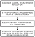
The invention provides a photovoltaic panel transmission angle control method based on reverse ray tracing, which comprises the following steps: s1, calculating a solar altitude angle and a solar azimuth angle; s2, determining a reverse light beam vector based on the solar altitude and the solar azimuth, and performing shielding judgment on the photovoltaic panel; calculating the value of the total irradiance of the photovoltaic panel; if the photovoltaic panel is blocked or the total irradiance value is smaller than the first threshold value, the photovoltaic panel is considered to be in the second state, otherwise, the photovoltaic panel is considered to be in the first state; s3, if the photovoltaic panel is in the first state, calculating a transmission adjusting angle, otherwise, not adjusting a transmission device; s4, if the moment time is within a first time interval, adjusting a roof inclination angle and an azimuth angle of the first photovoltaic panel; and if the time at the moment falls into a second time interval, adjusting the inclination angle of the roof and the azimuth angle of the second photovoltaic panel. The invention solves the technical problem that the accurate shading judgment of the photovoltaic panels under a plurality of staggered interfaces is difficult, and effectively improves the photovoltaic conversion efficiency.
Description
Technical Field
The invention relates to the field of control, in particular to a photovoltaic panel transmission angle control method based on reverse ray tracing.
Background
With the application of renewable energy, the effective conversion efficiency of solar photovoltaic systems becomes a key point of attention. The blocking of the photovoltaic panel and the directional directivity of the solar azimuth direction are one of the reasons for further improving the conversion efficiency. The application scene of solar energy utilization is realized by the photovoltaic panels to gradually permeate from a flat non-urban area to an urban area, however, different from the non-urban area, the flat large-area open space is difficult to exist in the city, and more photovoltaic panels are laid on the roof or the outer surface of a building without a large-area horizontal plane. In the prior art, the shielding judgment of the photovoltaic panel mainly aims at modeling other possible building type shielding objects, and the shielding of part of the photovoltaic panel on other photovoltaic panels cannot be considered under the condition that the photovoltaic panel is on a plurality of staggered interfaces. In addition, there is also not prior art to simultaneously carry out ray tracing to mobilizable potentially sheltered from photovoltaic board and the potentially photovoltaic board that shelters from for it judges to be difficult to carry out accurate sheltering from to the photovoltaic board under the crisscross interface of polylith.
Disclosure of Invention
In order to solve the technical problem that in the prior art, accurate shading judgment is difficult to be carried out on photovoltaic panels under a plurality of staggered interfaces, and then the maximum photovoltaic conversion efficiency cannot be effectively exerted, the invention provides a photovoltaic panel transmission angle control method based on reverse ray tracing, which comprises the following steps:
s1, calculating a solar altitude angle and a solar azimuth angle according to a local dimensionality, a solar hour angle and a declination angle;
s2, determining a reverse light beam vector based on the solar altitude angle and the solar azimuth angle, and performing shielding judgment on the photovoltaic panel; calculating the value of the total irradiance of the photovoltaic panel; if the photovoltaic panel is blocked or the total irradiance value is smaller than a first threshold value, the photovoltaic panel is considered to be in a second state, otherwise, the photovoltaic panel is considered to be in a first state;
the photovoltaic panel comprises a first photovoltaic panel and a second photovoltaic panel;
s3, if the photovoltaic panel is in the first state, calculating a transmission adjusting angle, otherwise, not adjusting a transmission device;
s4, if the moment time is within a first time interval, adjusting the inclination angle of the photovoltaic panel and the azimuth angle of the photovoltaic panel of the first photovoltaic panel; if the time at the moment falls into a second time interval, adjusting the inclination angle of the photovoltaic panel and the azimuth angle of the photovoltaic panel of a second photovoltaic panel;
the shielding judgment is based on the intersection point of the reverse light beam vector and the plane where the shielding object interface element is located, and if the distance between the intersection point and the geometric center of the shielding object interface element is smaller than a first distance threshold value, the shielding object interface element is judged to shield the photovoltaic panel interface element; traversing all the shelter interface micro elements and all the photovoltaic panel interface micro elements, if any shelter interface micro element shelters the photovoltaic panel interface micro elements, judging that the photovoltaic panel interface micro elements are sheltered, otherwise, judging that the photovoltaic panel interface micro elements are not sheltered; if the interface infinitesimal of the photovoltaic panel exceeding the first proportion is shielded, judging that the photovoltaic panel is shielded;
the shelter comprises a non-photovoltaic shelter and a photovoltaic panel.
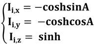
Preferably, when the true sun is less than 12, the backward light beam of the time photovoltaic panel interface infinitesimal i at the moment is towards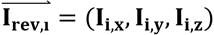 Comprises the following steps:
wherein the content of the first and second substances, reverse beam vector of a photovoltaic panel interface infinitesimal I, I i,x Is the coordinate of the reverse beam vector x direction of the photovoltaic panel interface infinitesimal I, I i,y Is the reverse light beam vector y-direction coordinate of the photovoltaic panel interface infinitesimal I, I i,z A reverse light beam vector z-direction coordinate of a photovoltaic panel interface infinitesimal i, wherein A is a solar azimuth angle and h is a solar altitude angle;
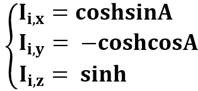
when the real sun is more than 12, the reverse light beam vector of the photovoltaic panel interface infinitesimal i at the moment is as follows:

wherein the content of the first and second substances, the reverse beam vector of the photovoltaic panel interface infinitesimal I, I i,x Is the coordinate of the reverse beam vector x direction of the photovoltaic panel interface infinitesimal I, I i,y Is the reverse light beam vector y-direction coordinate of the photovoltaic panel interface infinitesimal I, I i,z And the coordinate of the reverse light beam vector z direction of the photovoltaic panel interface infinitesimal i, wherein A is the solar azimuth angle and h is the solar altitude angle.
Preferably, the transmission adjusting angle comprises adjusting the inclination angle and the azimuth angle of the photovoltaic panel;
the actual adjustment angle of the inclination angle of the photovoltaic panel is the smaller value of the inclination angle of the adjusting photovoltaic panel and the inclination angle of the boundary photovoltaic panel, and the calculation method for calculating the inclination angle of the adjusting photovoltaic panel comprises the following steps: wherein, in the step (A),
 h is the solar altitude angle for calculating and adjusting the inclination angle of the photovoltaic panel;
the actual adjustment angle of the azimuth angle of the photovoltaic panel is the smaller value of the azimuth angle of the calculation adjustment photovoltaic panel and the azimuth angle of the boundary photovoltaic panel, and the calculation method for calculating the azimuth angle of the adjustment photovoltaic panel comprises the following steps: wherein, in the step (A),
 and (4) calculating and adjusting the azimuth angle of the photovoltaic panel, wherein A is the sun azimuth angle, and t is the place.
Preferably, the blocking judgment of the photovoltaic panel is boolean calculation, and the boolean calculation formula is as follows:

wherein Flag is ij Is a shielding judgment value, x ij Is the x-direction coordinate of the intersection point of the plane of the shield interface element j and the reverse beam vector 0 X-direction coordinate, y, of geometric center of barrier interface element ij Is the y-direction coordinate of the intersection point of the plane of the barrier interface infinitesimal j and the reverse light beam vector 0 Is the y-direction coordinate of the geometric center of the shutter interface element, is a threshold value in the x-direction,
 y-direction threshold, | is a bitwise or operation.
Preferably, the step of judging the occlusion of the interface infinitesimal i of the photovoltaic panel further includes:
go through all interfaces of the shelter Obtaining the judgment vector of the shelter to the infinitesimal i of the interface of the photovoltaic panel
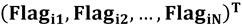 ;
;
Multiplying each shielding judgment value in the shielding object judgment vector, and if the shielding object judgment is multiplied by Flag i-wall And 1, the interface infinitesimal i of the photovoltaic panel is not shielded by all interfaces of the shielding object.
Preferably, the shielding judgment of the photovoltaic panel interface infinitesimal i includes:

wherein Flag is i Flag for the judgment of the occlusion of i of the interface infinitesimal of the photovoltaic panel i-wall Flag for non-photovoltaic panel source shelter judgment i-roof And judging the source shielding of the photovoltaic panel.
Preferably, the total irradiance value is an average value of the sum of all the total irradiance values of all the photovoltaic panel micro-elements i, and a calculation formula of the total irradiance value of the photovoltaic panel micro-elements i is as follows:

wherein, I global,i Is the total irradiance value, I, of the photovoltaic panel infinitesimal I dir,i Is the direct illumination value of a photovoltaic panel infinitesimal I, I dif,i Is the scattered irradiance value, flag, of the photovoltaic panel infinitesimal i i Is a shielding judgment value, I, of a photovoltaic panel infinitesimal I dir0 For this moment in time the intensity of direct solar radiation, solar incident angle, I, for a photovoltaic panel infinitesimal I dif0 For this purpose, the time-horizontal plane scattered radiation intensity, SVF i The sky angle coefficient of the photovoltaic panel infinitesimal i.
Preferably, the calculation method of the solar altitude angle is as follows:

wherein h is the solar altitude, the local latitude is taken as the position;
 is the solar hour angle;
 is the declination angle;
the calculation method of the solar azimuth angle comprises the following steps:
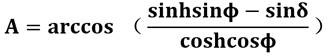
wherein A is the solar azimuth angle, h is the solar altitude angle, the local latitude is;
 is the solar hour angle;
 the declination angle.
Preferably, the inclination angle of the photovoltaic panel is adjusted by a first adjusting mechanism, the azimuth angle of the photovoltaic panel is adjusted by a second adjusting mechanism, and the second adjusting mechanism and the first adjusting mechanism are connected to the same support.
Preferably, the first adjusting mechanism is located at the lower part of the bracket, and the second adjusting mechanism is located at the upper part of the bracket.
According to the invention, the photovoltaic panel and other shelters possibly sheltered in buildings are subjected to infinitesimal splitting, and the sheltering condition of the shelters on the photovoltaic panel is effectively and accurately judged based on the reverse ray tracing of each photovoltaic panel infinitesimal, so that the technical problem of accurately sheltering judgment of the photovoltaic panels under a plurality of staggered interfaces is solved. The limitation of photovoltaic board application scene has been solved to above-mentioned scheme for the photovoltaic board can set up at multiple building top, and does not confine to planar roof structure or ground, makes when the building top of multiple angle sets up, all can effectively shelter from the judgement, promotes the conversion efficiency of photovoltaic board, and the effectual judgement flow of this scheme can avoid unnecessary to rotate, further reduces energy loss and control complexity.
Drawings
In order to more clearly illustrate the embodiments of the invention or the technical solutions in the prior art, the drawings used in the description of the embodiments or the prior art will be briefly described below, and it is obvious that the drawings in the following description are only some embodiments of the invention, and it is obvious for those skilled in the art that other drawings can be obtained based on these drawings without creative efforts.
Fig. 1 is a flowchart of a photovoltaic panel driving angle control method based on backward ray tracing according to an embodiment of the present invention;
fig. 2 is a schematic diagram of a reverse ray tracing vector of a photovoltaic panel driving angle control method based on reverse ray tracing according to an embodiment of the present invention;
fig. 3 is a structural diagram of a photovoltaic panel driving angle control method based on backward ray tracing according to an embodiment of the present invention;
fig. 4 is a structural diagram of an unadjusted state of a photovoltaic panel driving angle control method based on backward ray tracing according to an embodiment of the present invention;
fig. 5 is a diagram illustrating a tilt angle adjustment state of a photovoltaic panel transmission angle control method based on backward ray tracing according to an embodiment of the present invention;
fig. 6 is a diagram illustrating a state of a tilt angle and an azimuth angle adjustment structure of a photovoltaic panel transmission angle control method based on backward ray tracing according to an embodiment of the present invention;
fig. 7 is a schematic occlusion diagram of three control strategies of a photovoltaic panel driving angle control method based on backward ray tracing according to an embodiment of the present invention.
Detailed Description
In order that the above objects, features and advantages of the present invention can be more clearly understood, a more particular description of the invention, taken in conjunction with the accompanying drawings and detailed description, is set forth below. It should be noted that the embodiments and features of the embodiments of the present application may be combined with each other without conflict.
In the following description, numerous specific details are set forth in order to provide a thorough understanding of the present invention, however, the present invention may be practiced otherwise than as specifically described herein, and thus the scope of the present invention is not limited by the specific embodiments disclosed below.
Example one
The embodiment provides a photovoltaic panel transmission angle control method based on reverse ray tracing, which comprises the following steps:
s1, calculating a solar altitude angle and a solar azimuth angle according to the local dimensionality, the solar hour angle and the declination angle.
The calculation method of the solar altitude angle comprises the following steps:

wherein h is the solar altitude angle, the local latitude is taken as the position;
 is the solar hour angle;
 is the declination angle;
the calculation method of the solar azimuth angle comprises the following steps:

wherein A is the solar azimuth angle, h is the solar altitude angle, the local latitude is;
 is the solar hour angle;
 the declination angle.
The calculation method of the solar declination angle comprises the following steps:

wherein the content of the first and second substances, the angle of declination is a declination angle,
 is the angle of the day.
The calculation method of the day angle comprises the following steps:

wherein, the first and the second end of the pipe are connected with each other, the day angle, N, the integral day, that is, the day is the Nth day of the current year, and INT is a evidence-obtaining symbol.
The calculation method of the solar time angle comprises the following steps:

wherein, T 0 When it is true sun.
S1, calculating a sun angle through an integral day, calculating a solar declination angle through the sun angle, and further calculating to obtain a solar azimuth angle and a solar altitude angle, so that a calculation basis is provided for the subsequent calculation of a solar incident beam reverse vector during the shielding calculation. Compared with other technical schemes for directly comparing the solar incident angle or the solar azimuth angle with the solar incident boundary angle, the purpose of calculating the solar azimuth angle and the solar altitude angle in the embodiment is to provide a finite element subdivision vector basis for back tracking, and compared with a method for directly comparing the solar incident angle or the solar azimuth angle, the method is higher in accuracy.
S2, determining a reverse light beam vector based on the solar altitude angle and the solar azimuth angle, and performing shielding judgment on the photovoltaic panel; calculating the value of the total irradiance value of the photovoltaic panel; if the photovoltaic panel is judged to be shielded or the total irradiance value is smaller than a first threshold value, the photovoltaic panel is considered to be in the second state, otherwise, the photovoltaic panel is considered to be in the first state;
the photovoltaic panel includes a first photovoltaic panel and a second photovoltaic panel.
The shielding judgment is based on the intersection point of the reverse light beam vector and the plane where the shielding object interface element is located, and if the distance between the intersection point and the geometric center of the shielding object interface element is smaller than a first distance threshold value, the shielding object interface element is judged to shield the photovoltaic panel interface element; traversing all the shelter interface micro-elements and all the photovoltaic panel interface micro-elements, if any shelter interface micro-element shelters the photovoltaic panel interface micro-element, judging that the photovoltaic panel interface micro-element is sheltered, otherwise, judging that the photovoltaic panel interface micro-element is not sheltered; if the interface infinitesimal of the photovoltaic panel exceeding the first proportion is shielded, judging that the photovoltaic panel is shielded; the shelter comprises a non-photovoltaic shelter and a photovoltaic panel.
When the true sun is less than 12, the reverse light beam direction of the time photovoltaic panel interface infinitesimal i at the moment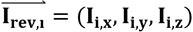 Comprises the following steps:

wherein the content of the first and second substances, the reverse beam vector of the photovoltaic panel interface infinitesimal I, I i,x Is the coordinate of the reverse beam vector x direction of the photovoltaic panel interface infinitesimal I i,y Is a reverse light beam vector y-direction coordinate of a photovoltaic panel interface infinitesimal I i,z The coordinate of a reverse light beam vector z direction of a photovoltaic panel interface infinitesimal i is shown, wherein A is a solar azimuth angle, and h is a solar altitude angle;
when the true sun is larger than 12, the reverse light beam vector of the time photovoltaic panel interface infinitesimal i at the moment is as follows:
wherein the content of the first and second substances, the reverse beam vector of the photovoltaic panel interface infinitesimal I, I i,x Is the coordinate of the reverse beam vector x direction of the photovoltaic panel interface infinitesimal I i,y Is the reverse light beam vector y-direction coordinate of the photovoltaic panel interface infinitesimal I, I i,z And the coordinate of the reverse light beam vector z direction of the photovoltaic panel interface infinitesimal i, wherein A is the solar azimuth angle and h is the solar altitude angle.
The x-axis represents the east-west direction (positive east), the y-axis represents the north-south direction (positive north), and the z-axis represents the height direction (positive up).
The embodiment constructs the reverse light beam vector corresponding to each photovoltaic panel interface infinitesimal element based on the solar incident angle or the solar azimuth angle, the whole shielding problem of the photovoltaic panel is converted into the finite element problem after subdivision, the discretized photovoltaic panel model is combined with a vector calculation mode, the more accurate shielding condition of each position of the photovoltaic panel is accurately and effectively judged, the problem that the photovoltaic panel shielding condition is inaccurate due to integral calculation in the prior art or simple modeling according to the height and the position of a shielding object, and the ray tracing is not timely is solved.
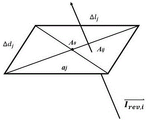
With a certain interface of a certain high-rise around the photovoltaic panel For example, the light can be blocked as shown in FIG. 2
 ,
, And with
 Respectively representing each interface of a high building
 Size in y-axis and x-axis, V wall Is the collection of all surrounding architectural interfaces.
 Representing the reverse beam vector, and the interface
 The plane intersects with A ij Dot, interface
 The geometric center is A 0 Then backward beam and interface
 Judgment of the occlusion relationship of (A) ij And A 0 And (6) judging the distance. If A is ij And A 0 The spacing in the x-axis direction being greater than
 Or a spacing in the y-axis direction greater than
 Then it means that the backward beam is not interfaced
 Is shielded. A. The ij And A 0 Respectively is (x) ij ,y ij ,z ij ) And (x) 0 ,y 0 ,z 0 ) The blocking judgment of the photovoltaic panel is Boolean calculation, and the Boolean calculation formula is as follows:

wherein Flag is ij As the occlusion determination value, x ij Is the x-direction coordinate of the intersection point of the plane of the barrier interface infinitesimal j and the reverse beam vector, x 0 X-direction coordinate, y, of geometric center of barrier interface element ij Is the y-direction coordinate of the intersection point of the plane of the barrier interface infinitesimal j and the reverse light beam vector 0 Is the y-direction coordinate of the geometric center of the shutter interface element, is the threshold value in the x-direction,
 is the y-direction threshold, | is a bitwise or operation.
If the result Flag is calculated ij A value of 1 indicates no occlusion.
Traverse all interfaces of the obstruction Obtaining the judgment vector of the shelter to the interface infinitesimal i of the photovoltaic panel
 (ii) a Multiplying each shielding judgment value in the shielding object judgment vector, and if the shielding object judgment is multiplied by Flag i-wall And 1, the interface infinitesimal i of the photovoltaic panel is not shielded by all interfaces of the shielding object.
The shielding judgment of the photovoltaic panel interface infinitesimal i comprises the following steps:

wherein Flag is i Flag for the occlusion determination of i for the photovoltaic panel interface infinitesimal i-wall Flag for non-photovoltaic plate source shelter judgment i-roof And judging the source shielding of the photovoltaic panel.
The total irradiance value is the average value of the sum of all the total irradiance values of all the photovoltaic panel micro-elements i, and the calculation formula of the total irradiance value of the photovoltaic panel micro-elements i is as follows:

wherein, I global,i Is the total irradiance value, I, of the photovoltaic panel infinitesimal I dir,i Is the direct irradiance value, I, of the photovoltaic panel infinitesimal I dif,i Is the scattered irradiance value, flag, of the photovoltaic panel infinitesimal i i Is a shielding judgment value of a photovoltaic panel infinitesimal I, I dir0 For this time, the intensity of direct solar radiation is, angle of incidence of the sun for photovoltaic panel infinitesimal I dif0 For this purpose, the time-horizontal plane scattered radiation intensity, SVF i And the sky angle coefficient of the photovoltaic panel infinitesimal i.
Compared with a method for modeling the environment to realize shielding judgment, the method for judging shielding of the photovoltaic panel in the complex environment has the advantages that the problem of shielding of the photovoltaic panel in the complex environment is calculated by adopting a reverse ray tracing method, whole calculation or unnecessary rendering aiming at the shadow is avoided, and the method has obvious calculation quantity advantages. In the embodiment, through the finite element subdivision of the photovoltaic panel, the vector of the central point of the micro element surface is taken as a calculation object, the subdivided photovoltaic panel is abstracted into a single point, and shelters in any mode, including but not limited to building shelters and shelters of the photovoltaic panel, can be flexibly considered. Especially, after the photovoltaic board removed, the design of this embodiment can in time realize causing new sheltering from the condition and carry out the snap judgments, realizes responding to sunshine light change and portable (including but not limited to the photovoltaic board that removes) shelter from the thing condition fast simultaneously.
And S3, if the photovoltaic panel is in a second state, namely the photovoltaic panel is shielded or the total irradiance value is smaller than the first threshold value, not calculating a transmission adjusting angle, and if not, adjusting the transmission device. The first threshold value is preferably 300W/m 2 。
S4, if the time is within a first time interval, adjusting a roof inclination angle and a first photovoltaic panel azimuth angle; and if the time falls into a second time interval, adjusting the inclination angle of the roof photovoltaic panel and the azimuth angle of the second photovoltaic panel.
The actual adjustment angle of the inclination angle of the photovoltaic panel is the smaller value of the inclination angle of the adjusting photovoltaic panel and the inclination angle of the boundary photovoltaic panel, and the calculation method for calculating the inclination angle of the adjusting photovoltaic panel comprises the following steps: wherein, in the process,
 h is the solar altitude angle for calculating and adjusting the inclination angle of the photovoltaic panel;
the actual adjustment angle of the azimuth angle of the photovoltaic panel is the smaller value of the azimuth angle of the calculation adjusting photovoltaic panel and the azimuth angle of the boundary photovoltaic panel, and the calculation method of the azimuth angle of the calculation adjusting photovoltaic panel comprises the following steps: wherein, in the process,
 and adjusting the azimuth angle of the photovoltaic panel for calculation, wherein A is the azimuth angle of the sun, and t is the local time.
Preferably, if the current location is between 20:00 to 4: and 00, at night, adjusting the photovoltaic panel to the original position by the transmission device, namely, the azimuth angle faces to the south direction, and the inclination angle of the photovoltaic panel is equal to the inclination angle of the roof.
If the current time is 4:00 to 12:00, then divide into two cases, if the total irradiance value meter reading is less than 300W/m2 (then it indicates that the current weather condition is mainly cloudy day, night) or the current photovoltaic panel is blocked, then the photovoltaic panel is kept at the previous control position. Otherwise, the transmission device adjusts the inclination angle of the photovoltaic panel to the optimal receiving angle, and simultaneously adjusts the azimuth angle of the west half photovoltaic panel to the optimal receiving angle.
If the current time is 12:00 to 20:00, dividing into two cases, and if the total irradiance value meter reading is less than 300W/m2 (indicating that the current meteorological condition is mainly cloudy and at night) or the current photovoltaic panel is shielded, keeping the photovoltaic panel at the previous control position. Otherwise, the transmission device adjusts the inclination angle of the photovoltaic panel to the optimal receiving angle, and simultaneously adjusts the azimuth angle of the east half photovoltaic panel to the optimal receiving angle.
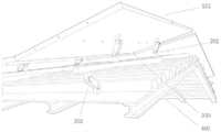
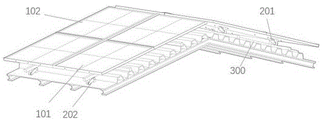
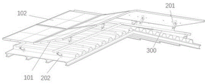
Fig. 3-6 show mechanical structure schematic diagrams for implementing the photovoltaic panel driving angle control method based on reverse ray tracing.
A plurality of photovoltaic panels 101 and a plurality of photovoltaic panels 102 are disposed on roof 400. The photovoltaic panels 101 and 102 can be individually controlled by the adjusting mechanisms 201 and 202, and the photovoltaic panels may have a problem of mutual shielding due to the angle change with sunlight. The inclination angle of the photovoltaic panel is adjusted by an adjusting mechanism 202, the azimuth angle of the photovoltaic panel is adjusted by an adjusting mechanism 201, the adjusting mechanism 201 and the adjusting mechanism 202 are connected to the same support, the adjusting mechanism 202 is located at the lower part of the support, and the adjusting mechanism 201 is located at the upper part of the support. As shown in fig. 4, the structure of the unadjusted state is shown, and both the adjustment mechanism 201 and the adjustment mechanism 202 are in the pressed state. As shown in fig. 5, which is a structure diagram of the state of adjusting the inclination angle, the adjusting mechanism 202 on the outer side adjusts the inclination angle of the photovoltaic panel upward according to the calculation, and if the calculated inclination angle of the photovoltaic panel exceeds the inclination angle of the boundary photovoltaic panel that can be adjusted by the adjusting mechanism 202, the adjustment angle of the actual inclination angle is the inclination angle of the boundary photovoltaic panel that can be adjusted by the adjusting mechanism 202. Fig. 6 is a structural diagram of a state of adjusting the inclination angle and the azimuth angle. Except that the adjusting mechanism 2012 close to the outer side adjusts the inclination angle of the photovoltaic panel upwards according to calculation, the adjusting mechanism 201 close to the right side is also lifted. The elevation angle of the adjustment mechanism 201 is determined by calculating the photovoltaic panel azimuth angle. If the calculated and adjusted azimuth angle of the photovoltaic panel exceeds the azimuth angle of the boundary photovoltaic panel that can be adjusted by the adjusting mechanism 201, the adjustment angle of the actual inclination angle is the azimuth angle of the boundary photovoltaic panel that can be adjusted by the adjusting mechanism 201.
Fig. 7 shows the direct irradiation and shielding of the photovoltaic panel by sunlight corresponding to the control strategies of the three adjusting mechanisms 201. The solid line represents the position of the photovoltaic panel before adjustment, and the dotted line represents the position of the adjustment mechanism 201 after response corresponding to the three control strategies. The light intensity obtained by the left graph and the right graph is the same and is slightly less than the sunlight intensity obtained by the photovoltaic panel of the middle graph. As shown in the left diagram of fig. 7, the left photovoltaic panel is lifted to the azimuth of the calculation adjustment photovoltaic panel or the azimuth of the boundary photovoltaic panel, and the right photovoltaic panel is kept still. As shown in the middle diagram of fig. 7, two photovoltaic panels share one adjusting mechanism 201, and the adjusting mechanism 201 is lifted to calculate and adjust the azimuth angle of the photovoltaic panel or the azimuth angle of the boundary photovoltaic panel, and the rotation height required under the control condition is high, when the height requirement which can be allowed by the conventional building cannot be met, the size of the azimuth angle of the boundary photovoltaic panel is greatly limited, so that the photovoltaic panel is often difficult to rotate to calculate and adjust the azimuth angle of the photovoltaic panel, and even if the theoretical middle diagram can obtain the maximum light intensity, the actual rotation process is difficult to obtain high light intensity because the azimuth angle of the boundary photovoltaic panel is smaller than the azimuth angles of the boundary photovoltaic panels of the left diagram and the right diagram. As shown in the right diagram of fig. 7, the azimuth angles of the two photovoltaic panels or the azimuth angle of the boundary photovoltaic panel are both lifted up to the calculation adjustment photovoltaic panel, in this case, the photovoltaic panel lifted up at the right side shields the photovoltaic panel at the left side, and the total received sunlight intensity is consistent with that of the right diagram. The left diagram is the control strategy of the adjusting mechanism 201 provided by this embodiment, and under the setting of this control strategy and the corresponding position of the adjusting mechanism 201, compared with the middle diagram, the height can be saved and a higher boundary photovoltaic panel azimuth angle can be possessed, compared with the right diagram, one mechanical rotation can be performed less, and the optimal technical effect of realizing higher sunlight intensity with the minimum rotation cost is comprehensively realized.
The adjusting mechanism effectively controls the azimuth angles and the inclination angles of the photovoltaic panels one by one, so that the adjusting mechanism is suitable for modeling and calculating in the reverse ray tracing process for all photovoltaic panel micro elements in the reverse ray tracing-based photovoltaic panel transmission angle control method provided by the embodiment. The technical problem that in the prior art, the photovoltaic panels under the multiple staggered interfaces cannot be accurately shielded and judged, and then the maximum photovoltaic conversion efficiency cannot be effectively exerted is effectively solved, the photovoltaic panels on the multiple staggered interfaces can be controlled one by one, the control logic is simple, and the calculation accuracy of the shielding efficiency is high.
The embodiment carries out infinitesimal split through the shelter that probably exists sheltering from to photovoltaic board and other buildings to based on carrying out reverse ray tracing to every photovoltaic board infinitesimal, the sheltering from the condition of photovoltaic board is gone on to the effective accurate judgement shelter, has solved the photovoltaic board under the polylith crisscross interface and has carried out the technical problem that accurate shelters from the judgement. The limitation that the scene was used to the photovoltaic board has been solved to above-mentioned scheme for the photovoltaic board can be set up at multiple building top, and does not confine to planar roof structure or ground, makes when the building top of multiple angle sets up, all can effectively shelter from the judgement, promotes the conversion efficiency of photovoltaic board. The 24-hour all-weather photovoltaic panel control logic based on double-circle control can avoid unnecessary rotation, reduce the rotation times of the mechanical device, prolong the service life of the mechanical device and further reduce energy loss and control complexity.
Example two
The present embodiment provides a computer-readable storage medium storing a computer program; the computer program, when executed by a processor in a computing device, causes the computing device to perform the method of embodiment one.
The foregoing description, for purposes of explanation, used specific nomenclature to provide a thorough understanding of the embodiments. It will be apparent, however, to one skilled in the art that the embodiments may be practiced without the specific details. Thus, the foregoing descriptions of specific embodiments described herein are presented for purposes of illustration and description. They are not intended to be exhaustive or to limit the embodiments to the precise forms disclosed. It will be apparent to those skilled in the art that many modifications and variations are possible in light of the above teaching. Further, as used herein to refer to the position of a component, the terms above and below, or their synonyms, do not necessarily refer to an absolute position relative to an external reference, but rather to a relative position of the component with reference to a drawing.
Moreover, the foregoing drawings and description include many concepts and features that may be combined in various ways to achieve various benefits and advantages. Thus, features, components, elements and/or concepts from the various figures may be combined to produce embodiments or implementations not necessarily shown or described in this specification. Furthermore, not all features, components, elements and/or concepts shown in a particular figure or description are necessarily required to be in any particular embodiment and/or implementation. It is to be understood that such embodiments and/or implementations fall within the scope of the present description.
Claims (9)
1. A photovoltaic panel transmission angle control method based on reverse ray tracing is characterized by comprising the following steps:
s1, calculating a solar altitude angle and a solar azimuth angle according to a local dimensionality, a solar hour angle and a declination angle;
s2, determining a reverse light beam vector based on the solar altitude angle and the solar azimuth angle, and performing shielding judgment on the photovoltaic panel; calculating the value of the total irradiance value of the photovoltaic panel; if the photovoltaic panel is blocked or the total irradiance value is smaller than a first threshold value, the photovoltaic panel is considered to be in a second state, otherwise, the photovoltaic panel is considered to be in a first state;
the photovoltaic panel comprises a first photovoltaic panel and a second photovoltaic panel;
s3, if the photovoltaic panel is in the first state, calculating a transmission adjusting angle, otherwise, not adjusting a transmission device;
s4, if the moment time falls into a first time interval, adjusting the inclination angle of the photovoltaic panel and the azimuth angle of the photovoltaic panel of the first photovoltaic panel; if the time at the moment falls into a second time interval, adjusting the inclination angle of the photovoltaic panel and the azimuth angle of the photovoltaic panel of a second photovoltaic panel;
the shielding judgment is based on an intersection point of a reverse light beam vector and a plane where a shielding object interface element is located, and if the distance between the intersection point and the geometric center of the shielding object interface element is smaller than a first distance threshold value, the shielding object interface element is judged to shield the photovoltaic panel interface element; traversing all the shelter interface micro-elements and all the photovoltaic panel interface micro-elements, if any shelter interface micro-element shelters the photovoltaic panel interface micro-element, judging that the photovoltaic panel interface micro-element is sheltered, otherwise, judging that the photovoltaic panel interface micro-element is not sheltered; if the photovoltaic panel interface infinitesimal exceeding the first proportion is shielded, judging that the photovoltaic panel is shielded;
the shelter comprises a non-photovoltaic shelter and a photovoltaic panel;
when the real solar time is less than 12, the reverse beam direction of the photovoltaic panel interface infinitesimal i at the moment Comprises the following steps:

wherein, the first and the second end of the pipe are connected with each other, reverse beam vector of a photovoltaic panel interface infinitesimal I, I i,x Is the coordinate of the reverse beam vector x direction of the photovoltaic panel interface infinitesimal I, I i,y Is the reverse light beam vector y-direction coordinate of the photovoltaic panel interface infinitesimal I, I i,z A reverse light beam vector z-direction coordinate of a photovoltaic panel interface infinitesimal i, wherein A is a solar azimuth angle and h is a solar altitude angle;
when the true sun is larger than 12, the reverse light beam vector of the time photovoltaic panel interface infinitesimal i at the moment is as follows:

wherein, the first and the second end of the pipe are connected with each other, reverse beam vector of a photovoltaic panel interface infinitesimal I, I i,x Is the coordinate of the reverse beam vector x direction of the photovoltaic panel interface infinitesimal I, I i,y Is a reverse light beam vector y-direction coordinate of a photovoltaic panel interface infinitesimal I i,z The coordinate of the reverse light beam vector z direction of the photovoltaic panel interface infinitesimal i is shown, wherein A is the solar azimuth angle and h is the solar altitude angle.
2. The reverse ray tracing-based photovoltaic panel driving angle control method as claimed in claim 1, wherein the driving adjustment angle includes adjusting a photovoltaic panel inclination angle and a photovoltaic panel azimuth angle;
the actual adjustment angle of the inclination angle of the photovoltaic panel is the smaller value of the inclination angle of the adjusting photovoltaic panel and the inclination angle of the boundary photovoltaic panel, and the calculation method for calculating the inclination angle of the adjusting photovoltaic panel comprises the following steps: wherein, in the step (A),
 h is the solar altitude angle for calculating and adjusting the inclination angle of the photovoltaic panel;
the actual adjustment angle of the azimuth angle of the photovoltaic panel is the smaller value of the azimuth angle of the calculation adjustment photovoltaic panel and the azimuth angle of the boundary photovoltaic panel, and the calculation method for calculating the azimuth angle of the adjustment photovoltaic panel comprises the following steps: wherein, in the process,
 and adjusting the azimuth angle of the photovoltaic panel for calculation, wherein A is the azimuth angle of the sun, and t is the local time.
3. The reverse ray tracing-based photovoltaic panel transmission angle control method according to claim 1, wherein the blocking judgment on the photovoltaic panel is a boolean calculation, and the boolean calculation formula is:

wherein Flag is ij Is a shielding judgment value, x ij Is the x-direction coordinate of the intersection point of the plane of the shield interface element j and the reverse beam vector 0 X-direction coordinate, y, of the geometric center of the barrier interface element ij Is the y-direction coordinate of the intersection point of the plane of the barrier interface infinitesimal j and the reverse light beam vector 0 Is the y-direction coordinate of the geometric center of the shutter interface element, is the threshold value in the x-direction,
 is the y-direction threshold, | is a bitwise or operation.
4. The reverse ray tracing-based photovoltaic panel transmission angle control method according to claim 1, wherein the step of determining the occlusion of the photovoltaic panel interface element i further comprises:
go through all interfaces of the shelter To obtain a light beamShelter judgment vector of volt plate interface infinitesimal i
 ;
;
Multiplying each shielding judgment value in the shielding object judgment vector in a cumulative manner, and if the shielding object judgment cumulative manner Flag i-wall And 1, the interface infinitesimal i of the photovoltaic panel is not shielded by all interfaces of the shielding object.
5. The reverse ray tracing-based photovoltaic panel transmission angle control method according to claim 4, wherein the judgment of the occlusion of the photovoltaic panel interface element i comprises:

wherein Flag is i Flag for the judgment of the occlusion of i of the interface infinitesimal of the photovoltaic panel i-wall Flag for non-photovoltaic plate source shelter judgment i-roof And judging the source shielding of the photovoltaic panel.
6. The reverse ray tracing-based photovoltaic panel driving angle control method as claimed in claim 1, wherein the total irradiance value is an average value of a sum of all irradiance values of all photovoltaic panel micro-elements i, and a calculation formula of the all irradiance value of the photovoltaic panel micro-elements i is:

wherein, I global,i Is the total irradiance value, I, of a photovoltaic panel infinitesimal I dir,i Is the direct irradiance value, I, of the photovoltaic panel infinitesimal I dif,i Is the scattered irradiance value, flag, of the photovoltaic panel infinitesimal i i Is a shielding judgment value of a photovoltaic panel infinitesimal I, I dir0 For this time, the intensity of direct solar radiation is, angle of incidence of the sun for photovoltaic panel infinitesimal I dif0 For this purpose, the time-horizontal plane scattered radiation intensity, SVF i And the sky angle coefficient of the photovoltaic panel infinitesimal i.
7. The backward ray tracing-based photovoltaic panel driving angle control method according to claim 1,
the calculation method of the solar altitude angle comprises the following steps:

wherein h is the solar altitude, the local latitude is;
 is the solar hour angle;
 is the declination angle;
the calculation method of the solar azimuth angle comprises the following steps:

wherein A is the solar azimuth angle, h is the solar altitude angle, the local latitude is taken as the position;
 is the solar hour angle;
 the declination angle.
8. The backward ray tracing-based photovoltaic panel driving angle control method according to claim 1, wherein the photovoltaic panel inclination angle is adjusted by a first adjusting mechanism, the photovoltaic panel azimuth angle is adjusted by a second adjusting mechanism, and the second adjusting mechanism is connected to the same support as the first adjusting mechanism.
9. The backward ray tracing-based photovoltaic panel driving angle control method of claim 8, wherein the first adjustment mechanism is located at a lower portion of the bracket, and the second adjustment mechanism is located at an upper portion of the bracket.
Priority Applications (1)
| Application Number | Priority Date | Filing Date | Title |
|---|---|---|---|
| CN202211150024.6A CN115237168B (en) | 2022-09-21 | 2022-09-21 | Photovoltaic panel transmission angle control method based on reverse ray tracing |
Applications Claiming Priority (1)
| Application Number | Priority Date | Filing Date | Title |
|---|---|---|---|
| CN202211150024.6A CN115237168B (en) | 2022-09-21 | 2022-09-21 | Photovoltaic panel transmission angle control method based on reverse ray tracing |
Publications (2)
| Publication Number | Publication Date |
|---|---|
| CN115237168A CN115237168A (en) | 2022-10-25 |
| CN115237168B true CN115237168B (en) | 2023-01-13 |
Family
ID=83681999
Family Applications (1)
| Application Number | Title | Priority Date | Filing Date |
|---|---|---|---|
| CN202211150024.6A Active CN115237168B (en) | 2022-09-21 | 2022-09-21 | Photovoltaic panel transmission angle control method based on reverse ray tracing |
Country Status (1)
| Country | Link |
|---|---|
| CN (1) | CN115237168B (en) |
Citations (12)
| Publication number | Priority date | Publication date | Assignee | Title |
|---|---|---|---|---|
| CN102519152A (en) * | 2011-11-30 | 2012-06-27 | 浙江大学 | Calculating method for mirror field optical efficiency on basis of graphics processing unit (GPU) tower type solar energy thermoelectric system |
| CN102930160A (en) * | 2012-11-02 | 2013-02-13 | 浙江大学 | Calculating method of mirror field optical efficiency of tower type solar thermoelectric system |
| CN104216419A (en) * | 2014-09-22 | 2014-12-17 | 西北工业大学 | No-shield tracking method of biaxial solar photovoltaic power generation system |
| CN104778316A (en) * | 2015-04-01 | 2015-07-15 | 浙江理工大学 | Photovoltaic power generation equipment radiation analysis method based on building information model |
| CN105760590A (en) * | 2016-02-04 | 2016-07-13 | 嘉兴国电通新能源科技有限公司 | Roof type photovoltaic array pitch optimizing method based on shadow radiation analysis |
| CN106708102A (en) * | 2017-03-07 | 2017-05-24 | 湖北追日新能源科技有限公司 | Shadow shielding detector |
| CN108319792A (en) * | 2018-02-09 | 2018-07-24 | 中国水利水电科学研究院 | Finite element simulation sunray covers computational methods |
| CN113221222A (en) * | 2021-05-10 | 2021-08-06 | 中国计量大学上虞高等研究院有限公司 | Method for arranging photovoltaic panels on building roof |
| CN113348623A (en) * | 2020-05-19 | 2021-09-03 | 华为技术有限公司 | Photovoltaic system |
| WO2022105446A1 (en) * | 2020-11-23 | 2022-05-27 | 深圳市中旭新能源有限公司 | Single-axis angle tracking method and system for intelligent photovoltaic module |
| CN114879751A (en) * | 2022-05-09 | 2022-08-09 | 阳光新能源开发股份有限公司 | Photovoltaic power generation control method and system and photovoltaic power station |
| CN114912171A (en) * | 2022-04-28 | 2022-08-16 | 西安建筑科技大学 | Building shielding-based sunlight radiation calculation method |
-
2022
- 2022-09-21 CN CN202211150024.6A patent/CN115237168B/en active Active
Patent Citations (12)
| Publication number | Priority date | Publication date | Assignee | Title |
|---|---|---|---|---|
| CN102519152A (en) * | 2011-11-30 | 2012-06-27 | 浙江大学 | Calculating method for mirror field optical efficiency on basis of graphics processing unit (GPU) tower type solar energy thermoelectric system |
| CN102930160A (en) * | 2012-11-02 | 2013-02-13 | 浙江大学 | Calculating method of mirror field optical efficiency of tower type solar thermoelectric system |
| CN104216419A (en) * | 2014-09-22 | 2014-12-17 | 西北工业大学 | No-shield tracking method of biaxial solar photovoltaic power generation system |
| CN104778316A (en) * | 2015-04-01 | 2015-07-15 | 浙江理工大学 | Photovoltaic power generation equipment radiation analysis method based on building information model |
| CN105760590A (en) * | 2016-02-04 | 2016-07-13 | 嘉兴国电通新能源科技有限公司 | Roof type photovoltaic array pitch optimizing method based on shadow radiation analysis |
| CN106708102A (en) * | 2017-03-07 | 2017-05-24 | 湖北追日新能源科技有限公司 | Shadow shielding detector |
| CN108319792A (en) * | 2018-02-09 | 2018-07-24 | 中国水利水电科学研究院 | Finite element simulation sunray covers computational methods |
| CN113348623A (en) * | 2020-05-19 | 2021-09-03 | 华为技术有限公司 | Photovoltaic system |
| WO2022105446A1 (en) * | 2020-11-23 | 2022-05-27 | 深圳市中旭新能源有限公司 | Single-axis angle tracking method and system for intelligent photovoltaic module |
| CN113221222A (en) * | 2021-05-10 | 2021-08-06 | 中国计量大学上虞高等研究院有限公司 | Method for arranging photovoltaic panels on building roof |
| CN114912171A (en) * | 2022-04-28 | 2022-08-16 | 西安建筑科技大学 | Building shielding-based sunlight radiation calculation method |
| CN114879751A (en) * | 2022-05-09 | 2022-08-09 | 阳光新能源开发股份有限公司 | Photovoltaic power generation control method and system and photovoltaic power station |
Also Published As
| Publication number | Publication date |
|---|---|
| CN115237168A (en) | 2022-10-25 |
Similar Documents
| Publication | Publication Date | Title |
|---|---|---|
| US8101848B2 (en) | Solar photovoltaic output for cloudy conditions with a solar tracking system | |
| CN103149947B (en) | Solar energy tracking method with umbra versa tracking | |
| CN105760590B (en) | A kind of roof type photovoltaic array spacing optimization method based on shade Emanations Analysis | |
| CN111079073A (en) | Building three-dimensional solar potential calculation method | |
| CN106933255B (en) | Different-terrain self-adaptive solar tracking method | |
| Madessa | Performance analysis of roof-mounted photovoltaic systems–The case of a Norwegian residential building | |
| CN106502274A (en) | A kind of optimize photovoltaic tracking system inter-module away from method | |
| Zhen et al. | The effects of inclined angle modification and diffuse radiation on the sun-tracking photovoltaic system | |
| Chen et al. | General method to obtain recommended tilt and azimuth angles for photovoltaic systems worldwide | |
| CN204539044U (en) | Photovoltaic array device | |
| CN111399548A (en) | Control method of tracking type photovoltaic power generation system capable of identifying weather types | |
| CN115268513A (en) | Control method and device of photovoltaic tracking support, electronic equipment and storage medium | |
| CN113419567B (en) | Tracking angle optimization method and system for tracking bracket | |
| Liu | Calculation and analysis of optimal tilt angle for PV/T hybrid collector | |
| CN115237168B (en) | Photovoltaic panel transmission angle control method based on reverse ray tracing | |
| CN108011574A (en) | Double-sided solar battery tracks the panel construction design method of stent | |
| Ng et al. | A tropical case study quantifying solar irradiance collected on a car roof for vehicle integrated photovoltaics towards low-carbon cities | |
| CN115098915A (en) | Method for optimizing arrangement of solar cell panels on roofs of parameterized buildings | |
| KR102191521B1 (en) | Photovoltaic system | |
| CN115061511A (en) | Water surface floating power station and control method | |
| US20230078507A1 (en) | Multi-phase backtracking of photovoltaic modules | |
| Schibuola et al. | Calculation procedure to improve the assessment of photovoltaic generation in solar maps | |
| Shi et al. | Optimization of 1-Axis Tracking with NS Rotating-Axis Orientation | |
| CN116594432B (en) | Sensorless control method and sensorless control equipment for photovoltaic power generation light tracking system | |
| US20230202684A1 (en) | Systems and methods for pointing photovoltaic arrays |
Legal Events
| Date | Code | Title | Description |
|---|---|---|---|
| PB01 | Publication | ||
| PB01 | Publication | ||
| SE01 | Entry into force of request for substantive examination | ||
| SE01 | Entry into force of request for substantive examination | ||
| GR01 | Patent grant | ||
| GR01 | Patent grant |